EP2623731A1 - Device and process for the processing of high pressure turbine blade in a gas turbine - Google Patents
Device and process for the processing of high pressure turbine blade in a gas turbine Download PDFInfo
- Publication number
- EP2623731A1 EP2623731A1 EP13000474.0A EP13000474A EP2623731A1 EP 2623731 A1 EP2623731 A1 EP 2623731A1 EP 13000474 A EP13000474 A EP 13000474A EP 2623731 A1 EP2623731 A1 EP 2623731A1
- Authority
- EP
- European Patent Office
- Prior art keywords
- tool
- gas turbine
- material layers
- foreign material
- deposits
- Prior art date
- Legal status (The legal status is an assumption and is not a legal conclusion. Google has not performed a legal analysis and makes no representation as to the accuracy of the status listed.)
- Withdrawn
Links
Images


Classifications
-
- B—PERFORMING OPERATIONS; TRANSPORTING
- B23—MACHINE TOOLS; METAL-WORKING NOT OTHERWISE PROVIDED FOR
- B23P—METAL-WORKING NOT OTHERWISE PROVIDED FOR; COMBINED OPERATIONS; UNIVERSAL MACHINE TOOLS
- B23P6/00—Restoring or reconditioning objects
- B23P6/002—Repairing turbine components, e.g. moving or stationary blades, rotors
-
- F—MECHANICAL ENGINEERING; LIGHTING; HEATING; WEAPONS; BLASTING
- F01—MACHINES OR ENGINES IN GENERAL; ENGINE PLANTS IN GENERAL; STEAM ENGINES
- F01D—NON-POSITIVE DISPLACEMENT MACHINES OR ENGINES, e.g. STEAM TURBINES
- F01D25/00—Component parts, details, or accessories, not provided for in, or of interest apart from, other groups
- F01D25/002—Cleaning of turbomachines
-
- G—PHYSICS
- G02—OPTICS
- G02B—OPTICAL ELEMENTS, SYSTEMS OR APPARATUS
- G02B23/00—Telescopes, e.g. binoculars; Periscopes; Instruments for viewing the inside of hollow bodies; Viewfinders; Optical aiming or sighting devices
- G02B23/24—Instruments or systems for viewing the inside of hollow bodies, e.g. fibrescopes
- G02B23/2476—Non-optical details, e.g. housings, mountings, supports
- G02B23/2492—Arrangements for use in a hostile environment, e.g. a very hot, cold or radioactive environment
-
- G—PHYSICS
- G01—MEASURING; TESTING
- G01N—INVESTIGATING OR ANALYSING MATERIALS BY DETERMINING THEIR CHEMICAL OR PHYSICAL PROPERTIES
- G01N21/00—Investigating or analysing materials by the use of optical means, i.e. using sub-millimetre waves, infrared, visible or ultraviolet light
- G01N21/84—Systems specially adapted for particular applications
- G01N21/88—Investigating the presence of flaws or contamination
- G01N21/95—Investigating the presence of flaws or contamination characterised by the material or shape of the object to be examined
- G01N21/954—Inspecting the inner surface of hollow bodies, e.g. bores
-
- Y—GENERAL TAGGING OF NEW TECHNOLOGICAL DEVELOPMENTS; GENERAL TAGGING OF CROSS-SECTIONAL TECHNOLOGIES SPANNING OVER SEVERAL SECTIONS OF THE IPC; TECHNICAL SUBJECTS COVERED BY FORMER USPC CROSS-REFERENCE ART COLLECTIONS [XRACs] AND DIGESTS
- Y10—TECHNICAL SUBJECTS COVERED BY FORMER USPC
- Y10T—TECHNICAL SUBJECTS COVERED BY FORMER US CLASSIFICATION
- Y10T29/00—Metal working
- Y10T29/49—Method of mechanical manufacture
- Y10T29/49316—Impeller making
- Y10T29/49318—Repairing or disassembling
-
- Y—GENERAL TAGGING OF NEW TECHNOLOGICAL DEVELOPMENTS; GENERAL TAGGING OF CROSS-SECTIONAL TECHNOLOGIES SPANNING OVER SEVERAL SECTIONS OF THE IPC; TECHNICAL SUBJECTS COVERED BY FORMER USPC CROSS-REFERENCE ART COLLECTIONS [XRACs] AND DIGESTS
- Y10—TECHNICAL SUBJECTS COVERED BY FORMER USPC
- Y10T—TECHNICAL SUBJECTS COVERED BY FORMER US CLASSIFICATION
- Y10T29/00—Metal working
- Y10T29/53—Means to assemble or disassemble
Definitions
- the invention relates to an apparatus and method for machining high pressure turbine blades of a gas turbine to remove deposits and / or contaminant layers in the region of cooling air recesses or cooling air holes on the high pressure turbine blades.
- Guides and blades in the high-pressure turbine area have to protect the component surfaces, which are in contact with the hot gas stream, a film cooling of the surface. This is generated by a different number of cooling air holes of the blade.
- the cooling air holes are partially or completely closed by different influences.
- the engine has to be removed from the aircraft and transferred to designated and authorized workshops. These workshops require equipment that is almost comparable to that of new parts manufacturing facilities.
- the aircraft must be equipped with a replacement engine during the period of engine repair. The cost of these measures is significant.
- the invention has for its object to provide a device and a method of the type mentioned, which allow a simple implementation and simple design reliable exposure and / or processing of the cooling air holes on high-pressure turbine blades of a gas turbine engine.
- the method for exposing the cooling-air bores to high-pressure turbine blades in a non-dismantled aircraft engine is performed. It is thus not necessary according to the invention to exchange an engine on an aircraft and to transfer the engine to a workshop. Rather, the method according to the invention is carried out on the installed engine.
- the deposits and / or foreign material layers are only removed at the points where they are to be released.
- the deposits and / or foreign material layers are radiated away by means of a pressurized liquid jet.
- the liquid used may be water and / or water with additives, oil, carbon dioxide or nitrogen.
- the use of high-energy light (laser) for the removal of foreign material layers is suitable.
- the method is preferably carried out under visual control, for example with the aid of an endoscope.
- the tools and / or devices required for carrying out the method are introduced into the high-pressure turbine region by borescope openings or burner openings of the combustion chamber provided in the gas turbine.
- the guidance of the tool and / or the devices to be machined area is realized according to the invention via a device which has the ability to change their shape individually, through the use of shape memory alloys.
- the fuel injectors of the combustion chamber are removed for the respective sections.
- an introducer sheath is introduced, through which the tool or the device is introduced radially. This has a 90 ° angle and is screwed into the opening of the removed fuel injectors.
- the tool or the device is pushed radially and axially through the insertion and thus passed directly to the corresponding section.
- the control of the device is realized by shape memory wires, which function as an "artificial muscle” in which they contract after heating and thereby bend the device.
- the cooling air holes are reached and processed at the leading edge of the guide vanes in this section.
- the tool head can be optionally controlled between the individual vanes and the cooling air holes are processed on suction and pressure side. In this way, the blades located axially behind the guide vanes are then accessible and their cooling air holes can also be processed with this method.
- the guidance of the tool and / or the devices to be machined area can also be carried out according to the invention via rail systems to be introduced, which may be more rigid, flexible or volume-increasing type.
- the rail systems are formed so that individual prefabricated pipe sections are successively introduced through the borescope opening or opening of the removed fuel injectors.
- the pipe sections should ideally be rigidly connected with each other.
- the device is based on the fact that, depending on the previous visual inspection, the corresponding area to be cleaned is activated.
- prefabricated elastic devices can be introduced into the combustion chamber and inflated by means of compressed air. By the devices then the actual tool can be guided to the destination.
- the Fig. 1 shows a simplified sectional view with blades 1a of a gas turbine engine high-pressure turbine and vanes 1 b of the high-pressure turbine.
- the structure corresponds to the prior art, so that can be dispensed with further explanations.
- the Fig. 2 shows a perspective, simplified representation of a portion of an inlet edge of a high-pressure turbine blade 1b, which is provided withde povertyausappelisme 3 (cooling air holes).
- the Fig. 2 shows in the upper part deposits 2, caused by foreign bodies in the gas stream and in the lower region deposits 2, caused by the internal cooling air, which flows out of thedeluftausappelisme 3 during operation of the gas turbine and deposits directly in the bore, which slowly enforce the bore diameter.
- a borescope or flexoscope To avoid the dismantling of engines, visual inspections are carried out with a borescope or flexoscope.
- This thin tube which has its origin in medical endoscopy, is internally equipped with a lens optic that can be inserted into a cavity to be examined.
- Fiber optics surround the optics and bring the light from a connected source to the point of inspection, from where a reflected image passes through the optics back to the viewer's eye or into a camera with a connected screen.
- the boroscopy provides images of places that would never be accessible without the dismantling of larger components.
- An aircraft engine has a variety of special openings for the boroscopy examination, which make it possible to guide the optics directly to the location to be examined, for example in each individual compressor stage. For the latter, a single opening is sufficient because the blades to be examined can be manually turned in front of the optics of the borescope. Rigid components without direct access are inspected with a flexoscope. Instead of the rigid tube, this tool has a flexible tube in which glass fibers replace the lens optics. With a working length of several meters, it is also possible to inspect components that can not be reached by a straight path.
- the Fig. 3 shows a schematic partial-axial sectional view of a gas turbine engine with basic accessibilities for Boroskop works. It can be seen that access to various areas of the gas turbine engine is possible by dismantling of attachments, opening access openings and the like.
- the Fig. 4 shows schematically the use of Boroskop devices in connection with the method according to the invention.
- a part of a housing 4 is shown, which is provided with a borescope opening 5 (access opening). This can be created by removing a lid or by dismantling an aggregate or the like.
- a manipulator 6 is introduced.
- the manipulator 6 is connected to a control unit 7, which may be connected, for example, to a hose 8, through which Media can be supplied or sucked.
- the control unit 7 has a screen 9.
- the manipulator 6 can be coupled with a tool to remove particles and to suck or analyze.
- a display and actuation unit or the control unit 7 allow by means of the screen 9 a review and control / inspection of the work.
- the invention makes it possible to carry out the cleaning of the cooling-air bores without dismantling the engine from the aircraft.
- miniaturized tools are supplied to the repair / cleaning area via the Boroskop openings located on the engine.
- particles from the pollution can be released by a tool with the aid of the borescope and collected in conjunction with a local suction device.
- An analysis of the dirt particles allows the differentiated selection of a suitable cleaning medium.
- the appropriate cleaning medium pasty shape or snow jets or dry ice jets
- the cleaning medium By the targeted selection of the cleaning medium, a dissolving of the contamination, or a resolution of the adhesive mechanism between the component and dirt particles is brought about.
- mechanical rework for example by a supplied with the help of the borescope micro-beam medium in conjunction with an effective suction device, the component surface or the cooling air hole is cleaned.
- a cleaning liquid adapted to the selected cleaning medium This can be directed with the help of Boroskops purposeful on the area to be cleaned.
- a suction device By a suction device, a large part of the dissolved dirt particles is sucked together with the cleaning liquid. A final visual check ensures that the area to be cleaned has again been adapted as far as possible to the drawing requirements and thus put into a proper state.
- the Fig. 5 shows an embodiment of an inventive device 10 with an insertion 11 and a tool head 12.
- the insertion 11 has a flange 13 which is screwed to the housing 4.
- a jet nozzle 14 and an optical system 15 for monitoring the processing of the cooling air holes 3 of the guide vanes 1 can be seen in the tool head 12.
- the shape memory wires 16, control lines 17 for resistance heating, a media tube 18 for the processing fluid and a glass fiber 19 for the optics and an inner support tube 20 can be seen.
- the Fig. 6 thus shows the actuating device, which is formed by the shape memory wires 16.
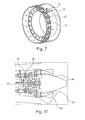
- the Fig. 7 shows a representation of a combustion chamber 21 with inserted insertion aid 11 and processing device 10.
- the attachment of the flange 13 (FIG. Fig. 6 ) are shown at the mounting locations of the fuel injectors.
- Fig. 8 is the processing device 10 in non-active, straight shape, used, shown in the combustion chamber 21, in Fig. 9 the processing device 10 is shown actively deflected, wherein the deflection, as explained above, takes place by activation of the shape memory elements.
- the Fig. 10 shows a further embodiment of the processing device according to the invention.
- an uninflated rail 22 is shown, which is introduced into an engine.
- this rail 22 is inflated and shown with inserted feed line for a machining tool 10.
- the rail 22 takes on a predetermined volume and is supported on the inner walls of the combustion chamber 21, whereby a sufficient rigidity for machining is generated.
- FIG. 11 schematically another embodiment of the processing device according to the invention is shown.
- This includes a cable system.
- a processing device 10 is attached to the borescope opening 5 or the engine outlet 23, over which a cable 24 is guided.
- the cable 24 must be introduced into the engine before machining.
- the machining tool 10 is fastened, by pulling on one of the rope ends, the machining tool 10 can be guided along the high-pressure turbine inlet guide vanes 16 to machine them.
- the invention makes it possible to carry out the exposure of the cooling air holes without removing the engine from the aircraft.
- miniaturized tools are fed to the repair / processing area via the Boroskop openings located on the engine.
- a final visual check ensures that the area to be edited has again been adapted as far as possible to the drawing requirements and thus put into a proper state.
Abstract
Description
Die Erfindung bezieht sich auf eine Vorrichtung und ein Verfahren zur Bearbeitung von Hochdruckturbinenschaufeln einer Gasturbine, um Ablagerungen und/oder Fremdstoffschichten im Bereich von Kühlluftausnehmungen oder Kühlluftbohrungen an den Hochdruckturbinenschaufeln zu entfernen.The invention relates to an apparatus and method for machining high pressure turbine blades of a gas turbine to remove deposits and / or contaminant layers in the region of cooling air recesses or cooling air holes on the high pressure turbine blades.
Leit- und Laufschaufeln im Hochdruckturbinenbereich besitzen zum Schutz der Bauteiloberflächen, welche mit dem heißen Gasstrom in Kontakt sind, eine Filmkühlung der Oberfläche. Diese wird durch eine unterschiedliche Anzahl von Kühlluftbohrungen der Schaufel erzeugt.Guides and blades in the high-pressure turbine area have to protect the component surfaces, which are in contact with the hot gas stream, a film cooling of the surface. This is generated by a different number of cooling air holes of the blade.
Während des Betriebes eines Triebwerks werden die Kühlluftbohrungen durch unterschiedliche Einflüsse teilweise bzw. vollständig verschlossen.During operation of an engine, the cooling air holes are partially or completely closed by different influences.
Dies führt zu einer Einschränkung, bzw. zu einem partiellen Verlust der Filmkühlung der Leit- und Laufschaufeloberfläche was zur Zerstörung des Bauteils führen kann. Aus diesen Gründen müssen die Kühlluftbohrungen an den Leit- und Laufschaufeln im Rahmen einer Reparaturmaßnahme wieder in einen ordnungsgemäßen Zustand gebracht werden.This leads to a restriction or to a partial loss of the film cooling of the guide and blade surface, which can lead to the destruction of the component. For these reasons, the cooling air holes on the vanes and blades must be returned to a proper condition as part of a repair operation.
Hierfür muss gemäß dem Stand der Technik das Triebwerk aus dem Luftfahrzeug ausgebaut und in dafür vorgesehene und autorisierte Werkstätten überführt werden. Diese Werkstätten benötigen eine Ausstattung, die mit der von Neuteilfertigungseinrichtungen nahezu vergleichbar ist. Darüber hinaus muss das Luftfahrzeug während der Zeitdauer der Triebwerksinstandsetzung mit einem Ersatztriebwerk ausgerüstet werden. Die Kosten für diese Maßnahmen sind erheblich.For this purpose, according to the prior art, the engine has to be removed from the aircraft and transferred to designated and authorized workshops. These workshops require equipment that is almost comparable to that of new parts manufacturing facilities. In addition, the aircraft must be equipped with a replacement engine during the period of engine repair. The cost of these measures is significant.
Der Erfindung liegt die Aufgabe zugrunde, eine Vorrichtung und ein Verfahren der eingangs genannten Art zu schaffen, welche bei einfacher Durchführung und einfacher Ausgestaltung eine zuverlässige Freilegung und/oder Bearbeitung der Kühlluftbohrungen an Hochdruckturbinenschaufeln eines Gasturbinentriebwerks ermöglichen.The invention has for its object to provide a device and a method of the type mentioned, which allow a simple implementation and simple design reliable exposure and / or processing of the cooling air holes on high-pressure turbine blades of a gas turbine engine.
Erfindungsgemäß wird die Aufgabe durch die Merkmalskombinationen der unabhängigen Ansprüche gelöst, die Unteransprüche zeigen weitere vorteilhafte Ausgestaltungen der Erfindung.According to the invention the object is achieved by the combination of features of the independent claims, the subclaims show further advantageous embodiments of the invention.
Erfindungsgemäß wird das Verfahren zur Freilegung der Kühlluftbohrungen an Hochdruckturbinenschaufeln bei einem nicht-demontierten Flugzeugtriebwerk durchgeführt. Es ist somit erfindungsgemäß nicht erforderlich, an einem Flugzeug ein Triebwerk zu tauschen und das Triebwerk in eine Werkstätte zu überführen. Vielmehr wird das erfindungsgemäße Verfahren am eingebauten Triebwerk durchgeführt.According to the invention, the method for exposing the cooling-air bores to high-pressure turbine blades in a non-dismantled aircraft engine is performed. It is thus not necessary according to the invention to exchange an engine on an aircraft and to transfer the engine to a workshop. Rather, the method according to the invention is carried out on the installed engine.
Erfindungsgemäß werden im nicht-demontierten Zustand mittels der erfindungsgemäßen Vorrichtung, nämlich mittels eines manuellen, teilautomatisierten oder automatisierten steuerbaren Werkzeugs die Ablagerungen und/oder Fremdstoffschichten nur an den Stellen entfernt, an denen diese gelöst werden sollen. Die Ablagerungen und/oder Fremdstoffschichten werden strahlend mittels eines Druckflüssigkeitsstrahls abgetragen. Die eingesetzte Flüssigkeit kann dabei Wasser und/oder Wasser mit Zusätzen, Öl, Kohlendioxid oder Stickstoff sein. Darüber hinaus ist auch die Nutzung von hochenergetischem Licht (Laser) für die Entfernung der Fremdstoffschichten geeignet.According to the invention, in the non-disassembled state by means of the device according to the invention, namely by means of a manual, semi-automated or automated controllable tool, the deposits and / or foreign material layers are only removed at the points where they are to be released. The deposits and / or foreign material layers are radiated away by means of a pressurized liquid jet. The liquid used may be water and / or water with additives, oil, carbon dioxide or nitrogen. In addition, the use of high-energy light (laser) for the removal of foreign material layers is suitable.
Nach dem Abtragen oder Entfernen der Ablagerungen und/oder Fremdstoffschichten ist es in Weiterbildung der Erfindung günstig, eine zusätzliche Spülung oder Reinigung der Hochdruckturbinenschaufeln vorzunehmen, insbesondere auch des Innenraums der Hochdruckturbinenschaufeln, um gegebenenfalls durch die Kühlluftausnehmung eingetretene Partikel auszuspülen oder auszubringen, beispielsweise mittels eines Gasstromes, beispielsweise Luft.After the removal or removal of the deposits and / or foreign material layers, it is favorable in a further development of the invention to carry out additional rinsing or cleaning of the high-pressure turbine blades, in particular also of the interior of the high-pressure turbine blades, in order to flush or expel any particles which may have entered through the cooling-air recess, for example by means of a gas flow , for example air.
Erfindungsgemäß wird das Verfahren bevorzugterweise unter visueller Kontrolle durchgeführt, beispielsweise mit Hilfe eines Endoskops.According to the invention, the method is preferably carried out under visual control, for example with the aid of an endoscope.
Weiterhin ist es erfindungsgemäß besonders günstig, wenn die zur Durchführung des Verfahrens benötigten Werkzeuge und/oder Geräte durch in der Gasturbine vorgesehenen Boroskop-Öffnungen oder Brenner-Öffnungen der Brennkammer in den Bereich der Hochdruckturbine eingebracht werden.Furthermore, it is particularly advantageous according to the invention if the tools and / or devices required for carrying out the method are introduced into the high-pressure turbine region by borescope openings or burner openings of the combustion chamber provided in the gas turbine.
Die Führung des Werkzeuges und/oder der Geräte zum zu bearbeitenden Bereich wird erfindungsgemäß über eine Vorrichtung realisiert, welche die Fähigkeit besitzt, ihre Form individuell, durch den Einsatz von Formgedächtnislegierungen zu verändern. Für die Bearbeitung werden die Kraftstoffeinspritzdüsen der Brennkammer für die jeweiligen Abschnitte ausgebaut. In die sich ergebende Öffnung wird eine Einführhülse eingebracht, durch welche das Werkzeug bzw. die Vorrichtung radial eingeführt wird. Diese weist einen 90° Winkel auf und wird in die Öffnung der ausgebauten Kraftstoffeinspritzdüsen verschraubt. Das Werkzeug bzw. die Vorrichtung wird radial und axial durch die Einführhilfe geschoben und somit direkt an den entsprechenden Abschnitt geleitet. Die Steuerung der Vorrichtung wird durch Formgedächtnisdrähte realisiert, welche als "künstlicher Muskel" fungieren in dem sie nach Erwärmung kontrahieren und die Vorrichtung dadurch biegen. Nach Abkühlung entspannen sich diese wieder und nehmen die ursprüngliche Form an. Bei der Vorrichtung sind zwei Drähte um 90° versetzt auf einem Schlauch, am Anfang und am Ende kraftschlüssig verspannt. Der Schlauch besitzt eine ausreichende Steifigkeit damit er eine erforderliche Rückstellkraft aufbringt, um die Drähte nach Abkühlung wieder in ihre ursprüngliche Form zu bringen. Die Drähte werden mit einem Schrumpfschlauch direkt an den Trägerschlauch gepresst und damit geführt, um die größtmögliche Verformung zu erreichen. Durch die um 90° versetzten Drähte bewegt sich das Werkzeug auf einer Kreisbahn. Mit einer gesteuerten Widerstandserwärmung kann der Draht entsprechend positioniert werden. Die Brennkammer wird in Abschnitte eingeteilt, womit die Erreichbarkeit aller Abschnitte der Leitschaufeln mit dem Werkzeug gewährleistet ist. Durch die tangentiale Bewegung des Werkzeugs auf einer Kreisbahn werden die Kühlluftbohrungen an der Eintrittskante der Leitschaufeln in diesem Abschnitt erreicht und bearbeitet. Durch den Wechsel des Werkzeugkopfes kann wahlweise auch zwischen die einzelnen Leitschaufeln gesteuert werden und die Kühlluftbohrungen auf Saug- und Druckseite bearbeitet werden. Auf diese Weise sind dann auch die axial hinter den Leitschaufeln befindlichen Laufschaufeln erreichbar und deren Kühlluftbohrungen können ebenfalls mit diesem Verfahren bearbeitet werden.The guidance of the tool and / or the devices to be machined area is realized according to the invention via a device which has the ability to change their shape individually, through the use of shape memory alloys. For processing, the fuel injectors of the combustion chamber are removed for the respective sections. In the resulting opening an introducer sheath is introduced, through which the tool or the device is introduced radially. This has a 90 ° angle and is screwed into the opening of the removed fuel injectors. The tool or the device is pushed radially and axially through the insertion and thus passed directly to the corresponding section. The control of the device is realized by shape memory wires, which function as an "artificial muscle" in which they contract after heating and thereby bend the device. After cooling, these relax again and take on the original shape. In the device two wires are offset by 90 ° on a hose, clamped non-positively at the beginning and at the end. The hose has sufficient rigidity so that it applies a required restoring force to bring the wires back to their original shape after cooling. The wires are pressed with a shrink tube directly to the carrier hose and thus guided to achieve the greatest possible deformation. Due to the 90 ° offset wires, the tool moves on a circular path. With a controlled resistance heating the wire can be positioned accordingly. The combustion chamber is divided into sections, which ensures the accessibility of all sections of the guide vanes with the tool. Due to the tangential movement of the tool on a circular path, the cooling air holes are reached and processed at the leading edge of the guide vanes in this section. By changing the tool head can be optionally controlled between the individual vanes and the cooling air holes are processed on suction and pressure side. In this way, the blades located axially behind the guide vanes are then accessible and their cooling air holes can also be processed with this method.
Die Führung des Werkzeuges und/oder der Geräte zum zu bearbeitenden Bereich kann erfindungsgemäß auch über einzubringende Schienensysteme erfolgen, welche starrer, flexibler oder auch volumenvergrößernder Art sein können. Die Schienensysteme sind so ausgebildet, dass einzelne vorgefertigte Rohrabschnitte nacheinander durch die Boroskop-Öffnung- oder Öffnung der ausgebauten Kraftstoffeinspritzdüsen eingeführt werden. Die Rohrabschnitte sollten dabei idealerweise mit einander starr verbunden werden. Die Vorrichtung basiert darauf, dass damit in Abhängigkeit der vorherigen visuellen Inspektion der entsprechende zu reinigende Bereich angesteuert wird. In gleicherweise können vorgefertigte elastische Vorrichtungen in die Brennkammer eingebracht und mittels Druckluft aufgeblasen werden. Durch die Vorrichtungen kann dann das eigentliche Werkzeug zum Bestimmungsort geführt werden.The guidance of the tool and / or the devices to be machined area can also be carried out according to the invention via rail systems to be introduced, which may be more rigid, flexible or volume-increasing type. The rail systems are formed so that individual prefabricated pipe sections are successively introduced through the borescope opening or opening of the removed fuel injectors. The pipe sections should ideally be rigidly connected with each other. The device is based on the fact that, depending on the previous visual inspection, the corresponding area to be cleaned is activated. Likewise, prefabricated elastic devices can be introduced into the combustion chamber and inflated by means of compressed air. By the devices then the actual tool can be guided to the destination.
Weiterhin ist es möglich Seilzugsysteme zur Führung und Navigation der Werkzeuge und/oder Geräte zu verwenden, welche durch verschiedene Öffnungen in das Triebwerk eingebracht werden. Dabei soll erfindungsgemäß eine Vorrichtung über der Boroskop-Öffnung oder einer Öffnung einer ausgebauten Kraftstoffeinspritzdüse und/oder dem Triebwerksaustritt und eine weitere ebenfalls am Triebwerksaustritt befestigt werden, um das Seilsystem zu führen. Am Seilsystem ist das Werkzeug und idealerweise eine Optik befestigt, welche durch Bewegung des Seils an die entsprechende Schaufel geführt wird.Furthermore, it is possible to use cable systems for guiding and navigation of the tools and / or devices, which are introduced through different openings in the engine. In this case, a device according to the invention on the Boroskop-opening or an opening of a removed fuel injector and / or the engine outlet and another also be attached to the engine outlet to guide the cable system. Attached to the cable system is the tool, and ideally an optic, which is guided by movement of the cable to the corresponding blade.
Auch nach Ausbau von Triebwerksanbauteilen, z. B. Kraftstoffeinspritzdüsen, Zündkerzen etc., ergeben sich oben genannten Öffnungen, die erfindungsgemäß verwendet werden können. Durch diese Öffnungen ist der Hochdruckturbinenbereich leicht zugänglich, ohne dass zusätzliche oder umfangreiche Demontagearbeiten erforderlich wären. Das erfindungsgemäße Verfahren zeichnet sich somit durch eine schnelle und kostengünstige Durchführbarkeit aus. Durch die Wiederherstellung der Funktion der Kühlluftbohrungen am im Luftfahrzeug eingebauten Triebwerk werden ein Abbau des Triebwerks und eine Instandsetzung in dafür autorisierten Betrieben sowie ein Einbau eines Leasing- oder Austauschtriebwerks in das Luftfahrzeug vermieden. Somit führt das erfindungsgemäße Verfahren zum einen zu einer erheblichen Kostensenkung, zum anderen zu einer erheblichen Verringerung der Stillstandszeit des Luftfahrzeugs.Even after removal of engine attachment parts, z. As fuel injectors, spark plugs, etc., arise above openings that can be used according to the invention. Through these openings, the high-pressure turbine area is easily accessible, without additional or extensive disassembly work would be required. The inventive method is thus characterized by a fast and inexpensive feasibility. Restoration of the cooling air holes on the aircraft's engine eliminates the need to disassemble the engine and repair it in authorized facilities, as well as to install a leasing or replacement engine in the aircraft. Thus, the inventive method leads to a significant cost reduction, on the one hand to a significant reduction in the downtime of the aircraft.
Im Folgenden wird die Erfindung anhand von Ausführungsbeispielen in Verbindung mit der Zeichnung beschrieben. Dabei zeigt:
- Fig. 1
- eine schematische Schnittansicht einer erfindungsgemäßen Hochdruckturbine mit Laufschaufel und Leitschaufeln,
- Fig. 2
- eine perspektivische Ansicht einer erfindungsgemäßen Leitschaufel mit Ablagerungen und/oder Fremdstoffschichten,
- Fig. 3
- eine schematische Darstellung eines Gasturbinentriebwerks mit Zugänglichkeiten für Boroskop-Arbeiten,
- Fig. 4
- eine vereinfachte, schematische Darstellung eines Boroskopie-Geräts,
- Fig. 5
- eine perspektivische Darstellung eines Ausführungsbeispiels der erfindungsgemäßen Vorrichtung mit Einführhilfe,
- Fig. 6
- eine Detailansicht der Vorrichtung gemäß
Fig. 5 , - Fig. 7
- eine vereinfachte Darstellung einer Brennkammer mit eingesetzter Vorrichtung,
- Fig. 8, 9
- Skizzen der erfindungsgemäßen Vorrichtung im inaktiven (
Fig. 8 ) und aktiven (Fig. 9 ) Zustand in der Brennkammer, - Fig. 10
- eine vereinfachte Skizze zur Darstellung des Einsatzes von aufblasbaren Schienen zur Werkzeugführung, und
- Fig. 11
- eine vereinfachte Skizze zur Darstellung des Einsatzes von Seilzugsystemen zur Werkzeugführung.
- Fig. 1
- a schematic sectional view of a high-pressure turbine according to the invention with blade and vanes,
- Fig. 2
- a perspective view of a guide blade according to the invention with deposits and / or foreign material layers,
- Fig. 3
- a schematic representation of a gas turbine engine with accessibility for Boroskop works,
- Fig. 4
- a simplified, schematic representation of a boroscopy device,
- Fig. 5
- a perspective view of an embodiment of the device according to the invention with insertion aid,
- Fig. 6
- a detailed view of the device according to
Fig. 5 . - Fig. 7
- a simplified representation of a combustion chamber with inserted device,
- Fig. 8, 9
- Sketches of the device according to the invention in inactive (
Fig. 8 ) and active (Fig. 9 ) State in the combustion chamber, - Fig. 10
- a simplified sketch illustrating the use of inflatable rails for tool guidance, and
- Fig. 11
- a simplified sketch to illustrate the use of cable systems for tool guidance.
Die
Die
Um die Demontage von Triebwerken zu ersparen, werden Sichtkontrollen mit einem Boroskop oder Flexoskop durchgeführt. Dieses dünne Rohr, das seinen Ursprung in der medizinischen Endoskopie hat, ist im Inneren mit einer Linsenoptik ausgestattet, die in einen zu untersuchenden Hohlraum eingeführt werden kann. Lichtleiterfasern umschließen die Optik und bringen das Licht aus einer angeschlossenen Quelle zum Ort der Inspektion, von wo ein reflektiertes Bild durch die Optik zurück zum Auge des Betrachters oder in eine Kamera mit angeschlossenem Bildschirm gelangt. So liefert die Boroskopie Bilder von Orten, die ohne die Demontage größerer Bauteile niemals zugänglich wären.To avoid the dismantling of engines, visual inspections are carried out with a borescope or flexoscope. This thin tube, which has its origin in medical endoscopy, is internally equipped with a lens optic that can be inserted into a cavity to be examined. Fiber optics surround the optics and bring the light from a connected source to the point of inspection, from where a reflected image passes through the optics back to the viewer's eye or into a camera with a connected screen. The boroscopy provides images of places that would never be accessible without the dismantling of larger components.
Ein Flugtriebwerk besitzt für die Boroskopie-Untersuchung eine Vielzahl spezieller Öffnungen, die es ermöglichen, die Optik direkt an die zu untersuchende Stelle zu führen, beispielsweise in jede einzelne Verdichterstufe. Für letztere reicht eine einzige Öffnung, weil die zu untersuchenden Schaufeln per Hand vor die Optik des Boroskops gedreht werden können. Starre Bauteile ohne direkten Zugang werden mit einem Flexoskop inspiziert. Anstelle des starren Rohrs besitzt dieses Werkzeug einen biegsamen Schlauch, in dem Glasfasern die Linsenoptik ersetzen. Mit einer Arbeitslänge von mehreren Metern können damit auch Bauteile inspiziert werden, die nicht auf geradem Weg zu erreichen sind.An aircraft engine has a variety of special openings for the boroscopy examination, which make it possible to guide the optics directly to the location to be examined, for example in each individual compressor stage. For the latter, a single opening is sufficient because the blades to be examined can be manually turned in front of the optics of the borescope. Rigid components without direct access are inspected with a flexoscope. Instead of the rigid tube, this tool has a flexible tube in which glass fibers replace the lens optics. With a working length of several meters, it is also possible to inspect components that can not be reached by a straight path.
Die
In
- A
Hochdruckverdichterlaufschaufeln Stufe 1, Eintrittskante- B
Hochdruckverdichterlaufschaufeln Stufe 1,Austrittskante Hochdruckverdichterlaufschaufeln Stufe 2, Eintrittskante- C
Hochdruckverdichterlaufschaufeln Stufe 3, Austrittskante Hochdruckverdichterlaufschaufeln Stufe 4, Eintrittskante- D
Hochdruckverdichterlaufschaufeln Stufe 5,Austrittskante Hochdruckverdichterlaufschaufeln Stufe 6, Eintrittskante- E
Hochdruckverdichterlaufschaufeln Stufe 9,Austrittskante Hochdruckverdichterlaufschaufeln Stufe 10, Eintrittskante- F
Hochdruckturbinenlaufschaufeln Stufe 1,Eintrittskante Hochdruckturbinenleitschaufeln Stufe 1, Brennkammer- G
Hochdruckturbinenlaufschaufeln Stufe 1,Austrittskante Hochdruckturbinenlaufschaufeln Stufe 2, Eintrittskante- H
Hochdruckturbinenlaufschaufeln Stufe 2,Austrittskante Niederdruckturbinenlaufschaufeln Stufe 1, Eintrittskante- I
Niederdruckturbinenlaufschaufeln Stufe 2, Austrittskante
- A
- High-pressure
compressor blades Stage 1, leading edge - B
- High-pressure
compressor blades Stage 1, outlet edge High-pressurecompressor blades Stage 2, leading edge - C
- High-pressure
compressor blades Level 3, outlet edge High-pressure compressor blades Stage 4, leading edge - D
- High-pressure
compressor blades Stage 5, outlet edge High-pressurecompressor blades Stage 6, leading edge - e
- High-pressure
compressor blades stage 9, outlet edge high-pressurecompressor blades stage 10, leading edge - F
- High-pressure
turbine blades stage 1, leading edge high-pressureturbine nozzles stage 1, combustion chamber - G
- High Pressure
Turbine Blades Stage 1, High Pressure Turbine BladesRun Out Stage 2, Leading Edge - H
- High-pressure
turbine blades Level 2, trailing edge Low-pressureturbine blades Level 1, leading edge - I
- Low pressure
turbine blades Level 2, trailing edge
Die
Der Manipulator 6 kann mit einem Werkzeug gekoppelt sein, um Partikel abzutragen und abzusaugen bzw. zu analysieren. Eine Anzeige- und Betätigungseinheit bzw. die Steuereinheit 7 ermöglichen mittels des Bildschirms 9 eine Überprüfung und Steuerung/Kontrolle der Arbeiten.The
Es versteht sich, dass die Darstellung der
Mit der Erfindung wird ermöglicht, die Reinigung der Kühlluftbohrungen auszuführen ohne das Triebwerk vom Luftfahrzeug abzubauen. Hierfür werden über die an dem Triebwerk befindlichen Boroskop-Öffnungen miniaturisierte Werkzeuge dem Reparatur-/Reinigungsbereich zugeführt. Es besteht die Möglichkeit, dass mit Hilfe des Boroskops durch ein Werkzeug Partikel der Verschmutzung gelöst werden und in Verbindung mit einer lokalen Absaugvorrichtung aufgefangen werden. Eine Analyse der Schmutzpartikel ermöglicht die differenzierte Auswahl eines entsprechenden Reinigungsmediums. Mit Hilfe des Boroskops wird das geeignete Reinigungsmedium (pastöse Form oder Schneestrahlen oder Trockeneisstrahlen) auf den betroffenen Bereich der Hochdruckturbinenleit-, bzw. -laufschaufel aufgebracht. Durch die gezielte Auswahl des Reinigungsmediums wird ein Anlösen der Verschmutzung, bzw. eine Auflösung des Haftmechanismus zwischen Bauteil und Schmutzpartikel herbeigeführt. Durch eine mechanische Nacharbeit, z.B. durch ein mit Hilfe des Boroskops zugeführtes Mikrostrahlmedium in Verbindung mit einer effektiven Absaugvorrichtung, wird die Bauteiloberfläche bzw. die Kühlluftbohrung gereinigt. Alternativ zur mechanischen Nacharbeit besteht auch die Möglichkeit, eine dem ausgewählten Reinigungsmedium angepasste Reinigungsflüssigkeit zu verwenden. Diese kann mit Hilfe des Boroskops zielgerichtet auf den zu reinigenden Bereich gerichtet werden. Durch eine Absaugvorrichtung wird ein Großteil der aufgelösten Schmutzpartikel zusammen mit der Reinigungsflüssigkeit abgesaugt. Eine abschließende visuelle Kontrolle stellt sicher, dass der zu reinigende Bereich wieder weitestgehend den Zeichnungsanforderungen angepasst und somit in einen ordnungsgemäßen Zustand versetzt wurde.The invention makes it possible to carry out the cleaning of the cooling-air bores without dismantling the engine from the aircraft. For this purpose, miniaturized tools are supplied to the repair / cleaning area via the Boroskop openings located on the engine. There is a possibility that particles from the pollution can be released by a tool with the aid of the borescope and collected in conjunction with a local suction device. An analysis of the dirt particles allows the differentiated selection of a suitable cleaning medium. With the help of the Boroskops the appropriate cleaning medium (pasty shape or snow jets or dry ice jets) is applied to the affected area of the Hochdruckturbinenleit- or -laufschaufel. By the targeted selection of the cleaning medium, a dissolving of the contamination, or a resolution of the adhesive mechanism between the component and dirt particles is brought about. By mechanical rework, for example by a supplied with the help of the borescope micro-beam medium in conjunction with an effective suction device, the component surface or the cooling air hole is cleaned. As an alternative to mechanical reworking, it is also possible to use a cleaning liquid adapted to the selected cleaning medium. This can be directed with the help of Boroskops purposeful on the area to be cleaned. By a suction device, a large part of the dissolved dirt particles is sucked together with the cleaning liquid. A final visual check ensures that the area to be cleaned has again been adapted as far as possible to the drawing requirements and thus put into a proper state.
Die
In der
Die
Die
In der
Die
In der
Mit der Erfindung wird ermöglicht, die Freilegung der Kühlluftbohrungen auszuführen ohne das Triebwerk vom Luftfahrzeug abzubauen. Hierfür werden über die an dem Triebwerk befindlichen Boroskop-Öffnungen miniaturisierte Werkzeuge dem Reparatur-/Bearbeitungsbereich zugeführt. Eine abschließende visuelle Kontrolle stellt sicher, dass der zu bearbeitende Bereich wieder weitestgehend den Zeichnungsanforderungen angepasst und somit in einen ordnungsgemäßen Zustand versetzt wurde.The invention makes it possible to carry out the exposure of the cooling air holes without removing the engine from the aircraft. For this purpose, miniaturized tools are fed to the repair / processing area via the Boroskop openings located on the engine. A final visual check ensures that the area to be edited has again been adapted as far as possible to the drawing requirements and thus put into a proper state.
- 1a1a
- Hochdruckturbinenlaufschaufel / LaufschaufelHigh pressure turbine blade / blade
- 1b1b
- Hochdruckturbinenleitschaufel / LeitschaufelHigh pressure turbine vane / vane
- 22
- Ablagerungen / Schmutzschichten / FremdstoffschichtenDeposits / dirt layers / foreign material layers
- 33
- Kühlluftausnehmungen (Kühlluftbohrungen)Cooling air recesses (cooling air holes)
- 44
- Gehäusecasing
- 55
- Zugangsöffnung / Boroskop-ÖffnungAccess opening / Boroskop-opening
- 66
- Manipulatormanipulator
- 77
- Steuereinheitcontrol unit
- 88th
- Schlauchtube
- 99
- Bildschirmscreen
- 1010
- Bearbeitungsvorrichtungprocessing device
- 1111
- Einführhilfe (Rohr)Insertion aid (tube)
- 1212
- Vorrichtungskopf mit WerkzeugDevice head with tool
- 1313
- Flanschflange
- 1414
- Spritzdüse / StrahldüseSpray nozzle / jet nozzle
- 1515
- Linse für Glasfaseroptik / OptikLens for fiber optics / optics
- 1616
- FormgedächtnisdrahtShape memory wire
- 1717
- Steuerungsleitung zur WiderstandserwärmungControl cable for resistance heating
- 1818
- Medienschlauchmedia tube
- 1919
- Glasfaser / Glasfaseroptik / optisches ÜberwachungselementGlass fiber / fiber optic / optical monitoring element
- 2020
- Innerer StützschlauchInner support tube
- 2121
- Brennkammercombustion chamber
- 2222
- Aufblasbare Schiene / SchienenelementInflatable rail / rail element
- 2323
- TriebwerksaustrittEngine exhaust
- 2424
- Seilrope
Claims (15)
Applications Claiming Priority (1)
| Application Number | Priority Date | Filing Date | Title |
|---|---|---|---|
| DE102012002275A DE102012002275A1 (en) | 2012-02-06 | 2012-02-06 | Apparatus and method for processing high-pressure turbine blades of a gas turbine |
Publications (1)
| Publication Number | Publication Date |
|---|---|
| EP2623731A1 true EP2623731A1 (en) | 2013-08-07 |
Family
ID=47721920
Family Applications (1)
| Application Number | Title | Priority Date | Filing Date |
|---|---|---|---|
| EP13000474.0A Withdrawn EP2623731A1 (en) | 2012-02-06 | 2013-01-31 | Device and process for the processing of high pressure turbine blade in a gas turbine |
Country Status (3)
| Country | Link |
|---|---|
| US (1) | US20130199040A1 (en) |
| EP (1) | EP2623731A1 (en) |
| DE (1) | DE102012002275A1 (en) |
Cited By (10)
| Publication number | Priority date | Publication date | Assignee | Title |
|---|---|---|---|---|
| FR3025018A1 (en) * | 2014-08-21 | 2016-02-26 | Snecma | CAMERA BRACKET ATTACHED TO A BEARING BRACKET OF A TURBOMACHINE |
| WO2017178581A1 (en) * | 2016-04-14 | 2017-10-19 | Lufthansa Technik Ag | Method and device for cleaning turbine blades |
| WO2019076876A1 (en) * | 2017-10-16 | 2019-04-25 | Lufthansa Technik Ag | Device and method for borescope inspection of jet engines |
| CN110064615A (en) * | 2019-05-14 | 2019-07-30 | 中国航发沈阳发动机研究所 | A kind of runner cleaning device and cleaning method |
| WO2019158144A1 (en) * | 2018-02-13 | 2019-08-22 | MTU Aero Engines AG | Tool and method for maintaining engines |
| CN112664278A (en) * | 2019-10-15 | 2021-04-16 | 通用电气公司 | System and method for servicing a turbine |
| CN112657766A (en) * | 2019-10-16 | 2021-04-16 | 通用电气公司 | System and method for maintaining a machine |
| CN112789390A (en) * | 2018-09-17 | 2021-05-11 | 赛峰航空器发动机 | Method for extracting foreign bodies accumulated in high-pressure distributor blades |
| DE102020129565A1 (en) | 2020-11-10 | 2022-05-12 | Dr. Ing. H.C. F. Porsche Aktiengesellschaft | Component with a lead structure for non-destructive testing of the component and corresponding test method |
| US11524350B1 (en) * | 2021-10-04 | 2022-12-13 | General Electric Company | Backwall strike braze repair |
Families Citing this family (30)
| Publication number | Priority date | Publication date | Assignee | Title |
|---|---|---|---|---|
| FR3011035B1 (en) * | 2013-09-25 | 2015-10-09 | Snecma | EXHAUST CASE COMPRISING A FLUID EVACUATION DEVICE, AND TURBOMACHINE |
| US9347899B2 (en) | 2013-12-06 | 2016-05-24 | Rolls-Royce Corporation | Thermographic inspection techniques |
| US9926517B2 (en) | 2013-12-09 | 2018-03-27 | General Electric Company | Cleaning solution and methods of cleaning a turbine engine |
| US9957066B2 (en) | 2015-02-13 | 2018-05-01 | General Electric Company | Detergent delivery methods and systems for turbine engines |
| BR102016021259B1 (en) | 2015-10-05 | 2022-06-14 | General Electric Company | METHOD AND SOLUTIONS FOR CLEANING A TURBINE ENGINE AND REAGENT COMPOSITION |
| US10197473B2 (en) | 2015-12-09 | 2019-02-05 | General Electric Company | System and method for performing a visual inspection of a gas turbine engine |
| DE102015225445A1 (en) * | 2015-12-16 | 2017-06-22 | Rolls-Royce Deutschland Ltd & Co Kg | Method and device for removing at least one foreign body from a gas duct of a turbomachine |
| US9951647B2 (en) * | 2015-12-17 | 2018-04-24 | General Electric Company | System and method for in situ cleaning of internal components of a gas turbine engine and a related plug assembly |
| US10428683B2 (en) | 2016-01-05 | 2019-10-01 | General Electric Company | Abrasive gel detergent for cleaning gas turbine engine components |
| US10005111B2 (en) | 2016-01-25 | 2018-06-26 | General Electric Company | Turbine engine cleaning systems and methods |
| US10544676B2 (en) * | 2016-02-03 | 2020-01-28 | General Electric Company | Situ gas turbine prevention of crack growth progression |
| US10323539B2 (en) * | 2016-03-01 | 2019-06-18 | General Electric Company | System and method for cleaning gas turbine engine components |
| US10563510B2 (en) * | 2016-03-18 | 2020-02-18 | General Electric Company | System and method for in situ repair of gas turbine engines |
| US10144096B2 (en) * | 2016-03-22 | 2018-12-04 | General Electric Company | Gas turbine in situ inflatable bladders for on-wing repair |
| US10316666B2 (en) * | 2016-04-12 | 2019-06-11 | General Electric Company | System and method for in situ balancing of a rotating component of a gas turbine engine |
| FR3056134B1 (en) * | 2016-09-20 | 2018-08-31 | Airbus Sas | ROBOTIC DEVICE FOR INSPECTING AN AIRCRAFT STRUCTURE |
| CN110049829A (en) * | 2016-10-14 | 2019-07-23 | 通用电气公司 | Gas-turbine unit cleaning system |
| FR3070288B1 (en) * | 2017-08-31 | 2019-09-06 | Safran Landing Systems | METHOD FOR CLEARING PIPES IN PARTS OBTAINED BY ADDITIVE MANUFACTURING |
| DE102017218425A1 (en) | 2017-10-16 | 2019-04-18 | Lufthansa Technik Ag | Device for cleaning turbine blades of a jet engine |
| US11707819B2 (en) | 2018-10-15 | 2023-07-25 | General Electric Company | Selectively flexible extension tool |
| US11702955B2 (en) | 2019-01-14 | 2023-07-18 | General Electric Company | Component repair system and method |
| US11752622B2 (en) | 2020-01-23 | 2023-09-12 | General Electric Company | Extension tool having a plurality of links |
| US11692650B2 (en) | 2020-01-23 | 2023-07-04 | General Electric Company | Selectively flexible extension tool |
| US11613003B2 (en) | 2020-01-24 | 2023-03-28 | General Electric Company | Line assembly for an extension tool having a plurality of links |
| US11572800B2 (en) * | 2020-02-14 | 2023-02-07 | Raytheon Technologies Corporation | Borescope port engine fluid wash |
| US11371437B2 (en) | 2020-03-10 | 2022-06-28 | Oliver Crispin Robotics Limited | Insertion tool |
| DE102020206205A1 (en) | 2020-05-18 | 2021-11-18 | MTU Aero Engines AG | Device and method for cleaning an aircraft engine |
| CN215444164U (en) * | 2021-01-29 | 2022-01-07 | 烟台杰瑞石油装备技术有限公司 | Turbine engine washing system |
| US11506077B2 (en) | 2021-02-04 | 2022-11-22 | General Electric Company | Inflatable device with guiding mechanism for effective engine cleaning |
| US11654547B2 (en) | 2021-03-31 | 2023-05-23 | General Electric Company | Extension tool |
Citations (7)
| Publication number | Priority date | Publication date | Assignee | Title |
|---|---|---|---|---|
| US3841764A (en) * | 1969-12-09 | 1974-10-15 | Secr Defence | Intrascope |
| GB2207210A (en) * | 1987-07-14 | 1989-01-25 | Rolls Royce Plc | Cleaning lance |
| DE19748795A1 (en) * | 1996-11-18 | 1998-05-20 | Olympus Optical Co | Endoscope with elongated introduction region and tip region on distal side of this |
| US6542230B1 (en) * | 1998-07-28 | 2003-04-01 | Keymed (Medical & Industrial) Ltd. | Apparatus for performing operations on a workpiece at an inaccessible location |
| US20050224474A1 (en) * | 2002-10-17 | 2005-10-13 | Kilburn Chris A | Method and apparatus for removing a thermal barrier coating from a power generation component |
| DE102008019892A1 (en) * | 2008-04-21 | 2009-10-29 | Mtu Aero Engines Gmbh | Method for cleaning an aircraft engine |
| WO2011058008A1 (en) * | 2009-11-10 | 2011-05-19 | Siemens Aktiengesellschaft | Inspection device and method for positioning an inspection device |
Family Cites Families (4)
| Publication number | Priority date | Publication date | Assignee | Title |
|---|---|---|---|---|
| CH660056A5 (en) * | 1982-07-09 | 1987-03-13 | Bbc Brown Boveri & Cie | Method and device for cleaning the blades of a gas turbine during operation |
| US6524395B1 (en) * | 2001-09-21 | 2003-02-25 | General Electric Company | Method and apparatus for locating and repairing cooling orifices of airfoils |
| DE102005045839A1 (en) * | 2005-09-24 | 2007-04-12 | Mtu Aero Engines Gmbh | Method for cleaning cavities on gas turbine components |
| GB0610578D0 (en) * | 2006-05-27 | 2006-07-05 | Rolls Royce Plc | Method of removing deposits |
-
2012
- 2012-02-06 DE DE102012002275A patent/DE102012002275A1/en not_active Withdrawn
-
2013
- 2013-01-31 US US13/755,719 patent/US20130199040A1/en not_active Abandoned
- 2013-01-31 EP EP13000474.0A patent/EP2623731A1/en not_active Withdrawn
Patent Citations (7)
| Publication number | Priority date | Publication date | Assignee | Title |
|---|---|---|---|---|
| US3841764A (en) * | 1969-12-09 | 1974-10-15 | Secr Defence | Intrascope |
| GB2207210A (en) * | 1987-07-14 | 1989-01-25 | Rolls Royce Plc | Cleaning lance |
| DE19748795A1 (en) * | 1996-11-18 | 1998-05-20 | Olympus Optical Co | Endoscope with elongated introduction region and tip region on distal side of this |
| US6542230B1 (en) * | 1998-07-28 | 2003-04-01 | Keymed (Medical & Industrial) Ltd. | Apparatus for performing operations on a workpiece at an inaccessible location |
| US20050224474A1 (en) * | 2002-10-17 | 2005-10-13 | Kilburn Chris A | Method and apparatus for removing a thermal barrier coating from a power generation component |
| DE102008019892A1 (en) * | 2008-04-21 | 2009-10-29 | Mtu Aero Engines Gmbh | Method for cleaning an aircraft engine |
| WO2011058008A1 (en) * | 2009-11-10 | 2011-05-19 | Siemens Aktiengesellschaft | Inspection device and method for positioning an inspection device |
Cited By (18)
| Publication number | Priority date | Publication date | Assignee | Title |
|---|---|---|---|---|
| FR3025018A1 (en) * | 2014-08-21 | 2016-02-26 | Snecma | CAMERA BRACKET ATTACHED TO A BEARING BRACKET OF A TURBOMACHINE |
| WO2017178581A1 (en) * | 2016-04-14 | 2017-10-19 | Lufthansa Technik Ag | Method and device for cleaning turbine blades |
| WO2019076876A1 (en) * | 2017-10-16 | 2019-04-25 | Lufthansa Technik Ag | Device and method for borescope inspection of jet engines |
| US11662319B2 (en) | 2017-10-16 | 2023-05-30 | Lufthansa Technik Ag | Device and method for borescope inspection of jet engines |
| WO2019158144A1 (en) * | 2018-02-13 | 2019-08-22 | MTU Aero Engines AG | Tool and method for maintaining engines |
| CN112789390A (en) * | 2018-09-17 | 2021-05-11 | 赛峰航空器发动机 | Method for extracting foreign bodies accumulated in high-pressure distributor blades |
| CN110064615A (en) * | 2019-05-14 | 2019-07-30 | 中国航发沈阳发动机研究所 | A kind of runner cleaning device and cleaning method |
| CN110064615B (en) * | 2019-05-14 | 2022-07-22 | 中国航发沈阳发动机研究所 | Flow passage cleaning device and cleaning method |
| US11480068B2 (en) | 2019-10-15 | 2022-10-25 | General Electric Company | Systems and method of servicing a turbomachine |
| EP3808944A1 (en) * | 2019-10-15 | 2021-04-21 | General Electric Company | Maintenance system with tubular assembly for servicing a turbomachine |
| CN112664278A (en) * | 2019-10-15 | 2021-04-16 | 通用电气公司 | System and method for servicing a turbine |
| CN112664278B (en) * | 2019-10-15 | 2023-10-31 | 通用电气公司 | System and method for repairing a turbomachine |
| EP3808935A1 (en) * | 2019-10-16 | 2021-04-21 | General Electric Company | Maintenane system with tubular assembly for servicing a turbomachine |
| CN112657766A (en) * | 2019-10-16 | 2021-04-16 | 通用电气公司 | System and method for maintaining a machine |
| CN112657766B (en) * | 2019-10-16 | 2023-12-05 | 通用电气公司 | System and method for maintaining a machine |
| DE102020129565A1 (en) | 2020-11-10 | 2022-05-12 | Dr. Ing. H.C. F. Porsche Aktiengesellschaft | Component with a lead structure for non-destructive testing of the component and corresponding test method |
| US11524350B1 (en) * | 2021-10-04 | 2022-12-13 | General Electric Company | Backwall strike braze repair |
| US11951557B2 (en) | 2021-10-04 | 2024-04-09 | General Electric Company | Backwall strike braze repair |
Also Published As
| Publication number | Publication date |
|---|---|
| DE102012002275A1 (en) | 2013-08-08 |
| US20130199040A1 (en) | 2013-08-08 |
Similar Documents
| Publication | Publication Date | Title |
|---|---|---|
| EP2623731A1 (en) | Device and process for the processing of high pressure turbine blade in a gas turbine | |
| EP2798161B1 (en) | Method for repairing a run-in layer of a compressor for a gas turbine | |
| DE102017218426B3 (en) | Apparatus and method for borescope inspection of jet engines | |
| EP2206575B1 (en) | Device for repairing blades of BLISK rotors with laser beam build-up welding | |
| EP2008756A1 (en) | Method and device for repairing BLISKs | |
| DE60119144T2 (en) | METHOD AND DEVICE FOR STEAM TURBINE INTAKE INSULATION INSPECTION | |
| EP2212036B1 (en) | Cleaning method | |
| EP3890895B1 (en) | Cleaning device for an application device | |
| EP3149288B1 (en) | Disassembly method for gas turbines and calibration device | |
| DE102008019892A1 (en) | Method for cleaning an aircraft engine | |
| EP2594738A1 (en) | Processing device and method for operating a seal element inside a housing of a gas turbine | |
| DE102016206246A1 (en) | Method and device for cleaning turbine blades | |
| DE102020205307A1 (en) | TURBO MACHINE REPAIR TOOL AND RELATED PROCEDURE | |
| DE102005030928B4 (en) | Cleaning device for arc welding or cutting torch and a corresponding method | |
| DE102004002551B4 (en) | Method for repairing components | |
| DE102016212602A1 (en) | CLEANING DEVICE WITH A CO2 BEAM LIQUID | |
| EP1701160A1 (en) | Method and device for testing an aircraft jet engine for oil leaks | |
| WO2010130246A1 (en) | Method for checking the purity of a lubricant system in a turbine component | |
| DE102020206205A1 (en) | Device and method for cleaning an aircraft engine | |
| DE102017112001A1 (en) | Device for cleaning surfaces | |
| DE102018202188A1 (en) | Main component for a multifunction tool and multifunction tool for the treatment of turbine elements | |
| DE102008008410A1 (en) | Line generator for a device for optical surface scanning, comprises a light source and an optical system that are arranged for releasing light beam in a radiation plane and received in a housing that is equipped with a discharge opening | |
| WO2021121457A1 (en) | State monitoring system having a borescope device for a gas turbine | |
| DE102014221892A1 (en) | Cleaning method and cleaning device for optical systems | |
| EP3305426A1 (en) | Liquid jet apparatus for machining channel walls and manoeuvring device of such a device |
Legal Events
| Date | Code | Title | Description |
|---|---|---|---|
| PUAI | Public reference made under article 153(3) epc to a published international application that has entered the european phase |
Free format text: ORIGINAL CODE: 0009012 |
|
| AK | Designated contracting states |
Kind code of ref document: A1 Designated state(s): AL AT BE BG CH CY CZ DE DK EE ES FI FR GB GR HR HU IE IS IT LI LT LU LV MC MK MT NL NO PL PT RO RS SE SI SK SM TR |
|
| AX | Request for extension of the european patent |
Extension state: BA ME |
|
| STAA | Information on the status of an ep patent application or granted ep patent |
Free format text: STATUS: THE APPLICATION IS DEEMED TO BE WITHDRAWN |
|
| 18D | Application deemed to be withdrawn |
Effective date: 20140208 |