EP3808935A1 - Maintenane system with tubular assembly for servicing a turbomachine - Google Patents
Maintenane system with tubular assembly for servicing a turbomachine Download PDFInfo
- Publication number
- EP3808935A1 EP3808935A1 EP20201190.4A EP20201190A EP3808935A1 EP 3808935 A1 EP3808935 A1 EP 3808935A1 EP 20201190 A EP20201190 A EP 20201190A EP 3808935 A1 EP3808935 A1 EP 3808935A1
- Authority
- EP
- European Patent Office
- Prior art keywords
- tubular body
- actuator
- accordance
- dispensing nozzle
- tip end
- Prior art date
- Legal status (The legal status is an assumption and is not a legal conclusion. Google has not performed a legal analysis and makes no representation as to the accuracy of the status listed.)
- Pending
Links
Images


Classifications
-
- F—MECHANICAL ENGINEERING; LIGHTING; HEATING; WEAPONS; BLASTING
- F01—MACHINES OR ENGINES IN GENERAL; ENGINE PLANTS IN GENERAL; STEAM ENGINES
- F01D—NON-POSITIVE DISPLACEMENT MACHINES OR ENGINES, e.g. STEAM TURBINES
- F01D5/00—Blades; Blade-carrying members; Heating, heat-insulating, cooling or antivibration means on the blades or the members
- F01D5/005—Repairing methods or devices
-
- F—MECHANICAL ENGINEERING; LIGHTING; HEATING; WEAPONS; BLASTING
- F01—MACHINES OR ENGINES IN GENERAL; ENGINE PLANTS IN GENERAL; STEAM ENGINES
- F01D—NON-POSITIVE DISPLACEMENT MACHINES OR ENGINES, e.g. STEAM TURBINES
- F01D25/00—Component parts, details, or accessories, not provided for in, or of interest apart from, other groups
-
- B—PERFORMING OPERATIONS; TRANSPORTING
- B23—MACHINE TOOLS; METAL-WORKING NOT OTHERWISE PROVIDED FOR
- B23P—METAL-WORKING NOT OTHERWISE PROVIDED FOR; COMBINED OPERATIONS; UNIVERSAL MACHINE TOOLS
- B23P6/00—Restoring or reconditioning objects
- B23P6/002—Repairing turbine components, e.g. moving or stationary blades, rotors
-
- F—MECHANICAL ENGINEERING; LIGHTING; HEATING; WEAPONS; BLASTING
- F01—MACHINES OR ENGINES IN GENERAL; ENGINE PLANTS IN GENERAL; STEAM ENGINES
- F01D—NON-POSITIVE DISPLACEMENT MACHINES OR ENGINES, e.g. STEAM TURBINES
- F01D21/00—Shutting-down of machines or engines, e.g. in emergency; Regulating, controlling, or safety means not otherwise provided for
- F01D21/003—Arrangements for testing or measuring
-
- F—MECHANICAL ENGINEERING; LIGHTING; HEATING; WEAPONS; BLASTING
- F01—MACHINES OR ENGINES IN GENERAL; ENGINE PLANTS IN GENERAL; STEAM ENGINES
- F01D—NON-POSITIVE DISPLACEMENT MACHINES OR ENGINES, e.g. STEAM TURBINES
- F01D25/00—Component parts, details, or accessories, not provided for in, or of interest apart from, other groups
- F01D25/28—Supporting or mounting arrangements, e.g. for turbine casing
- F01D25/285—Temporary support structures, e.g. for testing, assembling, installing, repairing; Assembly methods using such structures
-
- G—PHYSICS
- G02—OPTICS
- G02B—OPTICAL ELEMENTS, SYSTEMS OR APPARATUS
- G02B23/00—Telescopes, e.g. binoculars; Periscopes; Instruments for viewing the inside of hollow bodies; Viewfinders; Optical aiming or sighting devices
- G02B23/24—Instruments or systems for viewing the inside of hollow bodies, e.g. fibrescopes
- G02B23/2476—Non-optical details, e.g. housings, mountings, supports
- G02B23/2484—Arrangements in relation to a camera or imaging device
-
- F—MECHANICAL ENGINEERING; LIGHTING; HEATING; WEAPONS; BLASTING
- F05—INDEXING SCHEMES RELATING TO ENGINES OR PUMPS IN VARIOUS SUBCLASSES OF CLASSES F01-F04
- F05D—INDEXING SCHEME FOR ASPECTS RELATING TO NON-POSITIVE-DISPLACEMENT MACHINES OR ENGINES, GAS-TURBINES OR JET-PROPULSION PLANTS
- F05D2220/00—Application
- F05D2220/30—Application in turbines
-
- F—MECHANICAL ENGINEERING; LIGHTING; HEATING; WEAPONS; BLASTING
- F05—INDEXING SCHEMES RELATING TO ENGINES OR PUMPS IN VARIOUS SUBCLASSES OF CLASSES F01-F04
- F05D—INDEXING SCHEME FOR ASPECTS RELATING TO NON-POSITIVE-DISPLACEMENT MACHINES OR ENGINES, GAS-TURBINES OR JET-PROPULSION PLANTS
- F05D2230/00—Manufacture
- F05D2230/72—Maintenance
-
- F—MECHANICAL ENGINEERING; LIGHTING; HEATING; WEAPONS; BLASTING
- F05—INDEXING SCHEMES RELATING TO ENGINES OR PUMPS IN VARIOUS SUBCLASSES OF CLASSES F01-F04
- F05D—INDEXING SCHEME FOR ASPECTS RELATING TO NON-POSITIVE-DISPLACEMENT MACHINES OR ENGINES, GAS-TURBINES OR JET-PROPULSION PLANTS
- F05D2230/00—Manufacture
- F05D2230/80—Repairing, retrofitting or upgrading methods
-
- F—MECHANICAL ENGINEERING; LIGHTING; HEATING; WEAPONS; BLASTING
- F05—INDEXING SCHEMES RELATING TO ENGINES OR PUMPS IN VARIOUS SUBCLASSES OF CLASSES F01-F04
- F05D—INDEXING SCHEME FOR ASPECTS RELATING TO NON-POSITIVE-DISPLACEMENT MACHINES OR ENGINES, GAS-TURBINES OR JET-PROPULSION PLANTS
- F05D2270/00—Control
- F05D2270/60—Control system actuates means
- F05D2270/62—Electrical actuators
-
- F—MECHANICAL ENGINEERING; LIGHTING; HEATING; WEAPONS; BLASTING
- F05—INDEXING SCHEMES RELATING TO ENGINES OR PUMPS IN VARIOUS SUBCLASSES OF CLASSES F01-F04
- F05D—INDEXING SCHEME FOR ASPECTS RELATING TO NON-POSITIVE-DISPLACEMENT MACHINES OR ENGINES, GAS-TURBINES OR JET-PROPULSION PLANTS
- F05D2270/00—Control
- F05D2270/60—Control system actuates means
- F05D2270/64—Hydraulic actuators
-
- F—MECHANICAL ENGINEERING; LIGHTING; HEATING; WEAPONS; BLASTING
- F05—INDEXING SCHEMES RELATING TO ENGINES OR PUMPS IN VARIOUS SUBCLASSES OF CLASSES F01-F04
- F05D—INDEXING SCHEME FOR ASPECTS RELATING TO NON-POSITIVE-DISPLACEMENT MACHINES OR ENGINES, GAS-TURBINES OR JET-PROPULSION PLANTS
- F05D2270/00—Control
- F05D2270/60—Control system actuates means
- F05D2270/65—Pneumatic actuators
-
- F—MECHANICAL ENGINEERING; LIGHTING; HEATING; WEAPONS; BLASTING
- F05—INDEXING SCHEMES RELATING TO ENGINES OR PUMPS IN VARIOUS SUBCLASSES OF CLASSES F01-F04
- F05D—INDEXING SCHEME FOR ASPECTS RELATING TO NON-POSITIVE-DISPLACEMENT MACHINES OR ENGINES, GAS-TURBINES OR JET-PROPULSION PLANTS
- F05D2270/00—Control
- F05D2270/60—Control system actuates means
- F05D2270/66—Mechanical actuators
-
- F—MECHANICAL ENGINEERING; LIGHTING; HEATING; WEAPONS; BLASTING
- F05—INDEXING SCHEMES RELATING TO ENGINES OR PUMPS IN VARIOUS SUBCLASSES OF CLASSES F01-F04
- F05D—INDEXING SCHEME FOR ASPECTS RELATING TO NON-POSITIVE-DISPLACEMENT MACHINES OR ENGINES, GAS-TURBINES OR JET-PROPULSION PLANTS
- F05D2270/00—Control
- F05D2270/80—Devices generating input signals, e.g. transducers, sensors, cameras or strain gauges
- F05D2270/804—Optical devices
- F05D2270/8041—Cameras
-
- G—PHYSICS
- G01—MEASURING; TESTING
- G01M—TESTING STATIC OR DYNAMIC BALANCE OF MACHINES OR STRUCTURES; TESTING OF STRUCTURES OR APPARATUS, NOT OTHERWISE PROVIDED FOR
- G01M15/00—Testing of engines
- G01M15/14—Testing gas-turbine engines or jet-propulsion engines
Definitions
- the field of the disclosure relates generally to turbomachine maintenance and, more particularly, to systems and a method for use in inspecting and/or repairing turbomachines.
- At least some known turbine engines include an outer case and at least one rotor that includes multiple stages of rotating airfoils, i.e., blades, which rotate with respect to the outer case.
- the outer case includes multiple stages of stationary airfoils, i.e., guide vanes.
- the blades and guide vanes are arranged in alternating stages.
- shrouds are disposed on the radially inner surfaces of a stator to form a ring seal around tips of the blades. Together, the blades, guide vanes, and shrouds define a primary flowpath inside the compressor and turbine sections of the rotary machine. This flowpath, combined with a flowpath through the combustor, defines a primary cavity within the turbine engine.
- the components of the turbine engine experience at least some material degradation as a function of the components' service history. Accordingly, for at least some known turbine engines, periodic inspections, such as borescope inspections, are performed to assess the condition of the turbine engine between service intervals.
- conditions observed during inspections include wear (e.g., from incursion of blade tips into the shrouds, particle-induced erosion, water droplet induced erosion, wear due to sliding contact between stationary components), impact (e.g., spallation of thermal barrier coating (TBC) or environmental barrier coating (EBC) from turbine-section components, leading edge burring/bending of compressor blades), cracking (e.g., thermal fatigue, low-cycle fatigue, high-cycle fatigue, creep rupture), edge-of-contact wear between stationary parts, oxidation or hot corrosion of high-temperature metallic sections, static seal degradation, and creep deformation (e.g., of guide vane sidewalls/airfoils, blade platforms, and blade tip shrouds).
- wear e.g., from incursion of blade tips into the shrouds, particle-induced erosion, water droplet induced erosion, wear due to sliding contact between stationary components
- impact e.g., spallation of thermal barrier coating (TBC) or environmental barrier coating (EBC) from turbine-section components, leading edge
- the turbine engines are at least partially disassembled from an airframe and moved to a facility to allow repair and/or replacement of damaged components.
- damaged components of at least some known turbine engines are primarily repaired at overhaul or component repair facilities that are offsite from a location of the airframe.
- disassembling turbine engines for regular service is a costly and time-consuming endeavor.
- turbine components may benefit from having service performed before the next regularly scheduled service interval.
- a system for use in servicing a machine includes a tubular body including a longitudinal axis, a tip end, a dispensing nozzle defined at the tip end, and an interior channel in flow communication with the dispensing nozzle.
- the tubular body is configured to be flexible.
- An actuator is configured to selectively modify an orientation of the tubular body, and a reservoir is in flow communication with the interior channel.
- the reservoir is configured to supply a maintenance fluid to the tubular body for discharge from the dispensing nozzle.
- a system for use in servicing a machine includes a tubular assembly including a guide tube that includes an interior.
- a tubular body is sized for insertion within, and deployable from, the interior of the guide tube.
- the tubular body includes a longitudinal axis, a tip end, a dispensing nozzle defined at the tip end, and an interior channel in flow communication with the dispensing nozzle, wherein the tubular body is configured to be flexible.
- An actuator is configured to selectively modify an orientation of the tubular body, wherein movement of the tubular body is restricted when positioned within the guide tube, and is unrestricted when deployed from the guide tube.
- An anchoring mechanism is coupled to a portion of the tubular body, wherein the anchoring mechanism is configured to couple the tubular body to an attachment point within the machine.
- a method for use in servicing a machine engine includes providing access to a maintenance location within the machine, wherein the maintenance location is at least partially defined by a target component, and positioning a tubular assembly at the maintenance location.
- the tubular assembly includes a tubular body having a tip end, a dispensing nozzle defined at the tip end, and an interior channel in flow communication with the dispensing nozzle, wherein the tubular body is configured to be flexible.
- the method also includes selectively modifying, with an actuator, an orientation of the tubular body relative to the target component such that the dispensing nozzle is positioned proximate a damaged area on the component, and discharging a maintenance fluid from the dispensing nozzle towards the damaged area.
- Approximating language may be applied to modify any quantitative representation that could permissibly vary without resulting in a change in the basic function to which it is related. Accordingly, a value modified by a term or terms, such as “about”, “approximately”, and “substantially”, are not to be limited to the precise value specified. In at least some instances, the approximating language may correspond to the precision of an instrument for measuring the value.
- range limitations may be combined and/or interchanged, such ranges are identified and include all the sub-ranges contained therein unless context or language indicates otherwise.
- Embodiments of the present disclosure relate to systems and a method for use in inspecting and/or repairing turbomachines, such as turbine engines.
- the systems described herein include a tubular body having a tip end on the distal end of the tubular body, a dispensing nozzle on the tip end, an interior channel in flow communication with the dispensing nozzle, and an actuator configured to selectively modify an orientation of the tubular body.
- the tubular body is fabricated from a flexible material, and the actuator is operable to move the tip end in one or more degrees of freedom.
- the interior flow channel is in flow communication with a reservoir that supplies a maintenance fluid for discharge from the dispensing nozzle.
- the maintenance fluid may be formed from a material tailored to enhance the performance, and/or extend the service life, of the turbomachine.
- the maintenance fluid may include a material for restoring lost thermal barrier coating or environmental barrier coating on a hot gas path component within a turbine engine.
- the tubular body is routed towards a maintenance location within the turbine engine containing a component in need of repair, such as a hot gas path component with a damaged coating.
- the actuator facilitates orienting the dispensing nozzle towards the location of the damaged coating on the component, and the dispensing nozzle discharges the maintenance fluid towards the component when in position.
- the maintenance fluid may be curable on the component to facilitate repairing the barrier coating in-situ.
- the systems and method described herein enable in-situ maintenance of turbine engine components in an efficient and cost-effective manner, thereby facilitating an increase in the amount of time the turbine engine may remain in service before disassembly for service and overhaul.
- FIG. 1 is a schematic diagram of an exemplary turbine engine 10 coupled to an airframe 11.
- Turbine engine 10 includes a fan assembly 12, a low-pressure or booster compressor assembly 14, a high-pressure compressor assembly 16, and a combustor assembly 18.
- Fan assembly 12, booster compressor assembly 14, high-pressure compressor assembly 16, and combustor assembly 18 are coupled in flow communication.
- Turbine engine 10 also includes a high-pressure turbine assembly 20 coupled in flow communication with combustor assembly 18 and a low-pressure turbine assembly 22.
- Fan assembly 12 includes an array of fan blades 24 extending radially outward from a rotor disk 26.
- Low-pressure turbine assembly 22 is coupled to fan assembly 12 and booster compressor assembly 14 through a first drive shaft 28, and high-pressure turbine assembly 20 is coupled to high-pressure compressor assembly 16 through a second drive shaft 30.
- Turbine engine 10 has an inlet 32 and a core exhaust 34.
- Turbine engine 10 further includes a centerline 36 about which fan assembly 12, booster compressor assembly 14, high-pressure compressor assembly 16, and turbine assemblies 20 and 22 rotate.
- FIG. 2 is a box diagram illustrating an exemplary turbine engine 10 and system 100 that may be used to maintain the turbine engine 10.
- turbine engine 10 further includes an outer case 102 having an access point 104 defined therein.
- turbine engine 10 may be at least partially disassembled while coupled to airframe 11 (shown in FIG. 1 ) to define access point 104.
- Example access points may include, but are not limited to, borescope ports, ignitor ports, and the like.
- Access point 104 provides access to a maintenance location 106 and to an attachment point 108 within turbine engine 10.
- Maintenance location 106 is at least partially defined by any component 110 of turbine engine 10, such as a shroud, a blade, or a guide vane, having a defect.
- component 110 may include a defect 112 on a thermal barrier coating and/or an environmental barrier coating on component 110, wherein defect 112 may be a spallation or the like on the coating.
- System 100 is positionable at maintenance location 106 to facilitate maintaining component 110, for example repairing defect 112.
- system 100 may be routed from exterior of outer case 102, through access point 104, and through turbine engine 10 to be positioned at maintenance location 106.
- system 100 is coupleable to attachment point 108 to facilitate stabilizing system 100 within turbine engine 10 for enabling performance of an operation by system 100 at maintenance location 106.
- attachment point 108 is defined by blades 114 or guide vanes 116 within turbine engine 10.
- system 100 couples to attachment point 108 by being mounted directly to one of blades 114 or one of guide vanes 116, or by wedging itself between adjacent blades 114 or guide vanes 116, for example.
- system 100 includes an inspection device 118, a repair device 120, and a leveling device 122, which may be distinct and separate devices, or may be integrated as a single unitary device.
- inspection device 118, repair device 120, and leveling device 122 are routable through turbine engine 10 for positioning at maintenance location 106 for performing an operation therein.
- inspection device 118 performs an initial inspection of turbine engine 10 to obtain repair location data.
- the repair location data may include the location and extent (i.e., the dimensions) of defect 112 on component 110.
- the repair location data is accessible by repair device 120 and leveling device 122 to enable the performance of subsequent operations at maintenance location 106.
- repair device 120 is operable for applying a repair material to component 110 in a location of defect 112, and leveling device 122 is operable for spreading the repair material across component 110.
- leveling device 122 is a flexible polymeric material having at least one flat edge. Inspection device 118, repair device 120, and leveling device 122 may be operated manually or in an automated manner. In one embodiment, movement of repair device 120 and leveling device 122 may be determined based on the repair location data.
- FIG. 3 is a side view illustration of an exemplary system 100 that may be used to repair turbine engine 10 (shown in FIG. 1 ), system 100 being in a retracted configuration.
- FIG. 4 is a side view illustration of system 100 in a deployed configuration and a first operational mode.
- FIG. 5 is a side view illustration of system 100 in the deployed configuration and a second operational mode.
- system 100 includes a tubular assembly 124 including a guide tube 126 and a tubular body 128.
- Guide tube 126 has a first portion 130 and a second portion 132, and an interior 134 extending through first portion 130 and second portion 132.
- First portion 130 and second portion 132 are oriented relative to each other to enable tubular assembly 124 to be selectively oriented when being routed through turbine engine 10.
- System 100 also includes tubular body 128 sized for insertion within, and deployable from, interior 134 of guide tube 126.
- tubular body 128 is retracted within guide tube 126 to define the retracted configuration.
- system 100 and more specifically tubular assembly 124, is positionable at maintenance location 106 to facilitate repairing defect 112 (both shown in FIG. 2 ).
- tubular assembly 124 is routed through turbine engine 10 while in the retracted configuration to facilitate maneuvering tubular body 128 towards maintenance location 106.
- guide tube 126 is a rigid or selectively rigidizable structure, which enables tubular assembly 124 to be routed through turbine engine 10 in a controlled and predictable manner.
- tubular body 128 is deployed from interior 134 of guide tube 126, such as when tubular assembly 124 has reached its destination and is positioned in proximity to a defect on component 110.
- tubular body 128 includes a longitudinal axis 136, a tip end 138, a dispensing nozzle 140 defined at tip end 138, and an interior channel 142 in flow communication with dispensing nozzle 140.
- Tubular body 128 is fabricated from a flexible material such as, but not limited to, a polymeric material.
- tubular body 128 may be formed from multiple individually articulable segments, or may be formed as a telescoping assembly. As such, tubular body 128 is orientable with multiple degrees of freedom.
- tubular assembly 124 also includes an actuator 144, a controller 146 that controls the operation of actuator 144, and at least one control line 148 extending between actuator 144 and controller 146.
- Actuator 144 facilitates selectively modifying an orientation of tubular body 128, and of tip end 138, relative to longitudinal axis 136 of tubular body 128.
- Tubular assembly 124 may include any actuator 144 that enables system 100 to function as described herein.
- actuator 144 may include one of a pneumatic actuator, a dielectric elastomer, an ionic polymer-metal composite, a shape memory alloy, a piezoelectric polymer, ionic conducting polymers, carbon nanotube/ionic liquid composites, ion gels, dielectric gels, functionalized hydrogels, liquid crystal polymers, magnetic fluid/particle composite gels, and cable/rope actuators.
- actuator 144 is a pneumatic actuator
- control line 148 includes a plurality of control channels 150 configured to channel pneumatic fluid therethrough. Controller 146 controls operation of actuator 144 and, in one embodiment, may be a pressure regulating device that selectively supplies pneumatic fluid to each control channel 150.
- controller 146 communicates with actuator 144 via wireless communication to control its operation.
- controller 146 is integrated with tubular assembly 124 and is inserted within turbine engine 10 along with tubular assembly 124. Commands may then be provided to controller 146 via wireless communication.
- controller 146 receives repair location data associated with an initial inspection of the machine, and at least partially automates operation of actuator 144 based on the repair location data.
- the repair location data may include a physical location of a defect on component 110, and a path in which tubular assembly 124 can be routed to reach the physical location.
- Controller 146 may be programmed with commands, based on the repair location data, that control movement of tubular assembly 124 to position dispensing nozzle 140 proximate a defect on component 110.
- tubular body 128 includes an outer sleeve 152, an inner sleeve 154, and control channels 150 positioned between outer sleeve 152 and inner sleeve 154.
- Control channels 150 extend along a length of tubular body 128, and are spaced circumferentially about inner sleeve 154.
- Actuator 144 may include any number of control channels 150 that enables system 100 to function as described herein, and the number of control channels 150 included in system 100 is selected to enable tip end 138 (shown in FIG. 4 ) to be orientable relative to longitudinal axis 136.
- actuator 144 includes three control channels 150 that are equally spaced about inner sleeve 154, including a first control channel 156, a second control channel 158, and a third control channel 160.
- Control channels 150 are individually and selectively controllable.
- control channels 150 are selectively inflatable and deflatable to adjust the orientation of tubular body 128.
- control channels 150 may be fully deflated, fully inflated, or partially inflated.
- inflating first control channel 156 individually facilitates bending tubular body 128 in a first direction 162
- inflating second control channel 158 individually facilitates bending tubular body 128 in a second direction 164
- inflating third control channel 160 individually facilitates bending tubular body 128 in a third direction 166.
- More than one control channel 150 may be actuated at the same time to facilitate bending tubular body 128 in directions other than first, second, and third directions 162, 164, and 166.
- the orientation of tubular body 128, and the degree to which tubular body 128 is bent is adjustable based on which control channels 150 are actuated and the degree to which control channels 150 are actuated.
- system 100 further includes a reservoir 168 in flow communication with interior channel 142.
- Reservoir 168 stores a volume of maintenance fluid 169 therein, and supplies the maintenance fluid 169 to tubular body 128 for discharge from dispensing nozzle 140.
- reservoir 168 includes an injection syringe 170 having a body portion 172 a push rod 174 that is manually operable for selectively metering an amount of maintenance fluid 169 to be supplied to tubular body 128.
- System 100 also includes a fluid supply line 176 extending between tubular body 128 and reservoir 168, and a valve 178 coupled along fluid supply line 176.
- Anchoring mechanism 180 is any device that enables tubular body 128 to be coupled to attachment point 108 within turbine engine 10 (both shown in FIG. 2 ).
- anchoring mechanism 180 may couple tubular body 128 to attachment point 108 with a physical attachment, such as a clamp, or with a suction attachment.
- anchoring mechanism 180 is an inflatable membrane 182 having a control line 184 in communication with controller 146. Inflatable membrane 182 is deflated when in the first operational mode shown in FIG. 4 , and is inflated when in the second operational mode shown in FIG. 5 .
- inflatable membrane 182 When inflated, inflatable membrane 182 is sized to wedge itself between adjacent blades 114 or guide vanes 116 (both shown in FIG. 2 ) that define attachment point 108 to facilitate immobilizing a portion of tubular body 128 at maintenance location 106 (shown in FIG. 2 ) while allowing actuation of the distal end of tubular body 128 using control channels 150.
- system 100 also includes a camera 186 coupled to tubular body 128.
- Camera 186 is operable to provide real-time visual feedback to an operator, for example, to facilitate routing tubular assembly 124 through turbine engine 10, and to facilitate orienting tip end 138 such that discharge of the maintenance fluid 169 onto an appropriate location of component 110.
- system 100 also includes a leveling device 188 coupled at tip end 138.
- Leveling device 188 is a flexible polymeric material having at least one substantially straight edge. Leveling device 188 may be used to distribute and/or level the maintenance fluid 169 discharged from dispensing nozzle 140 across component 110 at maintenance location 106 (both shown in FIG. 2 ).
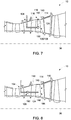
- FIG. 7 is a schematic illustration of a portion of turbine engine 10 having system 100 positioned therein.
- turbine engine 10 is minimally disassembled to provide access to maintenance location 106 within turbine engine 10.
- maintenance location 106 may be at least partially defined by component 110 having defect 112 (shown in FIG. 2 ) thereon.
- Component 110 may include, but is not limited to, a shroud member.
- maintenance location 106 is also defined by blades 114.
- Tubular assembly 124 is positioned at maintenance location 106 to facilitate maintenance of component 110, such as by repairing defect 112.
- tubular assembly 124 is routed from access point 104 and through turbine engine 10 for positioning at maintenance location 106.
- Anchoring mechanism 180 is used to couple tubular body 128 to attachment point 108. The orientation of tubular body 128 may then be adjusted to facilitate positioning dispensing nozzle 140 proximal to a damaged area 190 on component 110.
- anchoring mechanism 180 facilitates coupling tubular body 128 to rotor blades 114 of turbine engine 10, and tubular body 128 is oriented to extend in a substantially radial direction relative to centerline 36 to reach damaged area 190.
- tubular body 128 is anchored on a rotor of turbine engine 10, and the rotor is turned to circumferentially position tubular body 128 proximate a damaged component 110, positioned at a different circumferential location relative to centerline 36.
- system 100 may be used to repair turbine engine 10 without having to remove and then re-route system 100 through turbine engine 10.
- FIG. 8 is a schematic illustration of a portion of turbine engine 10 having system 100 positioned therein.
- maintenance location 106 is at least partially defined by component 110.
- Component 110 may include, but is not limited to, blade 114.
- Tubular assembly 124 is positioned at maintenance location 106 to facilitate maintaining component 110.
- tubular assembly 124 is routed from access point 104 and through turbine engine 10 for positioning at maintenance location 106.
- Anchoring mechanism 180 is used to couple tubular body 128 to attachment point 108. The orientation of tubular body 128 may then be adjusted to facilitate positioning dispensing nozzle 140 proximate a damaged area 192 on component 110.
- anchoring mechanism 180 facilitates coupling tubular body 128 to guide vanes 116 of turbine engine 10, and tubular body 128 is oriented to extend in a substantially axial direction relative to centerline 36 to reach damaged area 192.
- An exemplary technical effect of the systems and methods described herein includes at least one of: (a) enabling in-situ maintenance of interior components of a turbine engine; (b) increasing the accessibility of difficult-to-reach locations within a turbine assembly for inspection and/or in situ repair; (c) reducing the time that turbine engines are out of service for maintenance; and (d) reducing unplanned service outages for a turbine engine.
- Exemplary embodiments of methods and systems for use in repairing turbine engines are not limited to the specific embodiments described herein, but rather, components of systems and/or steps of the methods may be utilized independently and separately from other components and/or steps described herein.
- the methods and systems may also be used in combination with other systems requiring inspection and/or repair of components, and are not limited to practice with only the systems and methods as described herein.
- the exemplary embodiment can be implemented and utilized in connection with many other applications, equipment, and systems that may benefit from using a service apparatus for inspection and/or repair.
Abstract
Description
- The field of the disclosure relates generally to turbomachine maintenance and, more particularly, to systems and a method for use in inspecting and/or repairing turbomachines.
- At least some known turbine engines include an outer case and at least one rotor that includes multiple stages of rotating airfoils, i.e., blades, which rotate with respect to the outer case. In addition, the outer case includes multiple stages of stationary airfoils, i.e., guide vanes. The blades and guide vanes are arranged in alternating stages. In at least some known rotary machines, shrouds are disposed on the radially inner surfaces of a stator to form a ring seal around tips of the blades. Together, the blades, guide vanes, and shrouds define a primary flowpath inside the compressor and turbine sections of the rotary machine. This flowpath, combined with a flowpath through the combustor, defines a primary cavity within the turbine engine.
- During operation, the components of the turbine engine experience at least some material degradation as a function of the components' service history. Accordingly, for at least some known turbine engines, periodic inspections, such as borescope inspections, are performed to assess the condition of the turbine engine between service intervals. Examples of conditions observed during inspections include wear (e.g., from incursion of blade tips into the shrouds, particle-induced erosion, water droplet induced erosion, wear due to sliding contact between stationary components), impact (e.g., spallation of thermal barrier coating (TBC) or environmental barrier coating (EBC) from turbine-section components, leading edge burring/bending of compressor blades), cracking (e.g., thermal fatigue, low-cycle fatigue, high-cycle fatigue, creep rupture), edge-of-contact wear between stationary parts, oxidation or hot corrosion of high-temperature metallic sections, static seal degradation, and creep deformation (e.g., of guide vane sidewalls/airfoils, blade platforms, and blade tip shrouds).
- During service intervals, the turbine engines are at least partially disassembled from an airframe and moved to a facility to allow repair and/or replacement of damaged components. For example, damaged components of at least some known turbine engines are primarily repaired at overhaul or component repair facilities that are offsite from a location of the airframe. However, disassembling turbine engines for regular service is a costly and time-consuming endeavor. In addition, turbine components may benefit from having service performed before the next regularly scheduled service interval.
- In one aspect, a system for use in servicing a machine is provided. The system includes a tubular body including a longitudinal axis, a tip end, a dispensing nozzle defined at the tip end, and an interior channel in flow communication with the dispensing nozzle. The tubular body is configured to be flexible. An actuator is configured to selectively modify an orientation of the tubular body, and a reservoir is in flow communication with the interior channel. The reservoir is configured to supply a maintenance fluid to the tubular body for discharge from the dispensing nozzle.
- In another aspect, a system for use in servicing a machine is provided. The system includes a tubular assembly including a guide tube that includes an interior. A tubular body is sized for insertion within, and deployable from, the interior of the guide tube. The tubular body includes a longitudinal axis, a tip end, a dispensing nozzle defined at the tip end, and an interior channel in flow communication with the dispensing nozzle, wherein the tubular body is configured to be flexible. An actuator is configured to selectively modify an orientation of the tubular body, wherein movement of the tubular body is restricted when positioned within the guide tube, and is unrestricted when deployed from the guide tube. An anchoring mechanism is coupled to a portion of the tubular body, wherein the anchoring mechanism is configured to couple the tubular body to an attachment point within the machine.
- In yet another aspect, a method for use in servicing a machine engine is provided. The method includes providing access to a maintenance location within the machine, wherein the maintenance location is at least partially defined by a target component, and positioning a tubular assembly at the maintenance location. The tubular assembly includes a tubular body having a tip end, a dispensing nozzle defined at the tip end, and an interior channel in flow communication with the dispensing nozzle, wherein the tubular body is configured to be flexible. The method also includes selectively modifying, with an actuator, an orientation of the tubular body relative to the target component such that the dispensing nozzle is positioned proximate a damaged area on the component, and discharging a maintenance fluid from the dispensing nozzle towards the damaged area.
- These and other features, aspects, and advantages of the present disclosure will become better understood when the following detailed description is read with reference to the accompanying drawings in which like characters represent like parts throughout the drawings, wherein:
-
FIG. 1 is a schematic illustration of an exemplary turbomachine; -
FIG. 2 is a box diagram illustrating an exemplary turbomachine and system that may be used to repair the turbomachine; -
FIG. 3 is a side view illustration of the system shown inFIG. 2 , the system being in a retracted configuration; -
FIG. 4 is a side view illustration of the system shown inFIG. 3 in a deployed configuration and a first operational mode; -
FIG. 5 is a side view illustration of the system shown inFIG. 3 in the deployed configuration and a second operational mode; -
FIG. 6 is a cross-sectional view of the system shown inFIG. 4 , taken along line 6-6; -
FIG. 7 is a schematic illustration of a portion of the turbomachine shown inFIG. 1 having the system shown inFIG. 3 positioned therein; and -
FIG. 8 is a schematic illustration of a portion of the turbomachine shown inFIG. 1 having the system shown inFIG. 3 positioned therein. - Unless otherwise indicated, the drawings provided herein are meant to illustrate features of embodiments of this disclosure. These features are believed to be applicable in a wide variety of systems comprising one or more embodiments of this disclosure. As such, the drawings are not meant to include all conventional features known by those of ordinary skill in the art to be required for the practice of the embodiments disclosed herein.
- In the following specification and the claims, reference will be made to a number of terms, which shall be defined to have the following meanings.
- The singular forms "a", "an", and "the" include plural references unless the context clearly dictates otherwise.
- "Optional" or "optionally" means that the subsequently described event or circumstance may or may not occur, and that the description includes instances where the event occurs and instances where it does not.
- Approximating language, as used herein throughout the specification and claims, may be applied to modify any quantitative representation that could permissibly vary without resulting in a change in the basic function to which it is related. Accordingly, a value modified by a term or terms, such as "about", "approximately", and "substantially", are not to be limited to the precise value specified. In at least some instances, the approximating language may correspond to the precision of an instrument for measuring the value. Here and throughout the specification and claims, range limitations may be combined and/or interchanged, such ranges are identified and include all the sub-ranges contained therein unless context or language indicates otherwise.
- Embodiments of the present disclosure relate to systems and a method for use in inspecting and/or repairing turbomachines, such as turbine engines. In the exemplary embodiment, the systems described herein include a tubular body having a tip end on the distal end of the tubular body, a dispensing nozzle on the tip end, an interior channel in flow communication with the dispensing nozzle, and an actuator configured to selectively modify an orientation of the tubular body. For example, the tubular body is fabricated from a flexible material, and the actuator is operable to move the tip end in one or more degrees of freedom. The interior flow channel is in flow communication with a reservoir that supplies a maintenance fluid for discharge from the dispensing nozzle. The maintenance fluid may be formed from a material tailored to enhance the performance, and/or extend the service life, of the turbomachine. For example, the maintenance fluid may include a material for restoring lost thermal barrier coating or environmental barrier coating on a hot gas path component within a turbine engine. In operation, the tubular body is routed towards a maintenance location within the turbine engine containing a component in need of repair, such as a hot gas path component with a damaged coating. The actuator facilitates orienting the dispensing nozzle towards the location of the damaged coating on the component, and the dispensing nozzle discharges the maintenance fluid towards the component when in position. The maintenance fluid may be curable on the component to facilitate repairing the barrier coating in-situ. As such, the systems and method described herein enable in-situ maintenance of turbine engine components in an efficient and cost-effective manner, thereby facilitating an increase in the amount of time the turbine engine may remain in service before disassembly for service and overhaul.
-
FIG. 1 is a schematic diagram of anexemplary turbine engine 10 coupled to anairframe 11.Turbine engine 10 includes afan assembly 12, a low-pressure orbooster compressor assembly 14, a high-pressure compressor assembly 16, and acombustor assembly 18.Fan assembly 12,booster compressor assembly 14, high-pressure compressor assembly 16, andcombustor assembly 18 are coupled in flow communication.Turbine engine 10 also includes a high-pressure turbine assembly 20 coupled in flow communication withcombustor assembly 18 and a low-pressure turbine assembly 22.Fan assembly 12 includes an array offan blades 24 extending radially outward from arotor disk 26. Low-pressure turbine assembly 22 is coupled tofan assembly 12 andbooster compressor assembly 14 through afirst drive shaft 28, and high-pressure turbine assembly 20 is coupled to high-pressure compressor assembly 16 through asecond drive shaft 30.Turbine engine 10 has aninlet 32 and acore exhaust 34.Turbine engine 10 further includes acenterline 36 about whichfan assembly 12,booster compressor assembly 14, high-pressure compressor assembly 16, andturbine assemblies - In operation, some of the air entering
turbine engine 10 throughinlet 32 is channeled throughfan assembly 12 towardsbooster compressor assembly 14. Compressed air is discharged frombooster compressor assembly 14 towards high-pressure compressor assembly 16. Highly compressed air is channeled from high-pressure compressor assembly 16 towardscombustor assembly 18, mixed with fuel, and the mixture is combusted withincombustor assembly 18. High temperature combustion gas generated bycombustor assembly 18 is channeled throughturbine assemblies turbine engine 10 viacore exhaust 34 and afan exhaust 38. -
FIG. 2 is a box diagram illustrating anexemplary turbine engine 10 andsystem 100 that may be used to maintain theturbine engine 10. In the exemplary embodiment,turbine engine 10 further includes anouter case 102 having anaccess point 104 defined therein. For example,turbine engine 10 may be at least partially disassembled while coupled to airframe 11 (shown inFIG. 1 ) to defineaccess point 104. Example access points may include, but are not limited to, borescope ports, ignitor ports, and the like.Access point 104 provides access to amaintenance location 106 and to anattachment point 108 withinturbine engine 10.Maintenance location 106 is at least partially defined by anycomponent 110 ofturbine engine 10, such as a shroud, a blade, or a guide vane, having a defect. For example,component 110 may include adefect 112 on a thermal barrier coating and/or an environmental barrier coating oncomponent 110, whereindefect 112 may be a spallation or the like on the coating. -
System 100 is positionable atmaintenance location 106 to facilitate maintainingcomponent 110, forexample repairing defect 112. For example,system 100 may be routed from exterior ofouter case 102, throughaccess point 104, and throughturbine engine 10 to be positioned atmaintenance location 106. In some embodiments,system 100 is coupleable toattachment point 108 to facilitate stabilizingsystem 100 withinturbine engine 10 for enabling performance of an operation bysystem 100 atmaintenance location 106. In the exemplary embodiment,attachment point 108 is defined byblades 114 or guidevanes 116 withinturbine engine 10. As will be described in more detail below,system 100 couples toattachment point 108 by being mounted directly to one ofblades 114 or one ofguide vanes 116, or by wedging itself betweenadjacent blades 114 or guidevanes 116, for example. - In the exemplary embodiment,
system 100 includes aninspection device 118, arepair device 120, and aleveling device 122, which may be distinct and separate devices, or may be integrated as a single unitary device. Each ofinspection device 118,repair device 120, and levelingdevice 122 are routable throughturbine engine 10 for positioning atmaintenance location 106 for performing an operation therein. For example, in one embodiment,inspection device 118 performs an initial inspection ofturbine engine 10 to obtain repair location data. The repair location data may include the location and extent (i.e., the dimensions) ofdefect 112 oncomponent 110. The repair location data is accessible byrepair device 120 and levelingdevice 122 to enable the performance of subsequent operations atmaintenance location 106. For example, in one embodiment,repair device 120 is operable for applying a repair material tocomponent 110 in a location ofdefect 112, and levelingdevice 122 is operable for spreading the repair material acrosscomponent 110. In one embodiment, levelingdevice 122 is a flexible polymeric material having at least one flat edge.Inspection device 118,repair device 120, and levelingdevice 122 may be operated manually or in an automated manner. In one embodiment, movement ofrepair device 120 and levelingdevice 122 may be determined based on the repair location data. -
FIG. 3 is a side view illustration of anexemplary system 100 that may be used to repair turbine engine 10 (shown inFIG. 1 ),system 100 being in a retracted configuration.FIG. 4 is a side view illustration ofsystem 100 in a deployed configuration and a first operational mode.FIG. 5 is a side view illustration ofsystem 100 in the deployed configuration and a second operational mode. In the exemplary embodiment,system 100 includes atubular assembly 124 including aguide tube 126 and atubular body 128.Guide tube 126 has afirst portion 130 and asecond portion 132, and an interior 134 extending throughfirst portion 130 andsecond portion 132.First portion 130 andsecond portion 132 are oriented relative to each other to enabletubular assembly 124 to be selectively oriented when being routed throughturbine engine 10.System 100 also includestubular body 128 sized for insertion within, and deployable from,interior 134 ofguide tube 126. For example, referring toFIG. 3 ,tubular body 128 is retracted withinguide tube 126 to define the retracted configuration. As noted above,system 100, and more specificallytubular assembly 124, is positionable atmaintenance location 106 to facilitate repairing defect 112 (both shown inFIG. 2 ). In operation,tubular assembly 124 is routed throughturbine engine 10 while in the retracted configuration to facilitate maneuveringtubular body 128 towardsmaintenance location 106. In addition,guide tube 126 is a rigid or selectively rigidizable structure, which enablestubular assembly 124 to be routed throughturbine engine 10 in a controlled and predictable manner. - Referring to
FIGS. 4 and5 ,tubular body 128 is deployed frominterior 134 ofguide tube 126, such as whentubular assembly 124 has reached its destination and is positioned in proximity to a defect oncomponent 110. In the exemplary embodiment,tubular body 128 includes alongitudinal axis 136, atip end 138, a dispensingnozzle 140 defined attip end 138, and aninterior channel 142 in flow communication with dispensingnozzle 140.Tubular body 128 is fabricated from a flexible material such as, but not limited to, a polymeric material. Alternatively,tubular body 128 may be formed from multiple individually articulable segments, or may be formed as a telescoping assembly. As such,tubular body 128 is orientable with multiple degrees of freedom. - For example,
tubular assembly 124 also includes anactuator 144, acontroller 146 that controls the operation ofactuator 144, and at least one control line 148 extending betweenactuator 144 andcontroller 146.Actuator 144 facilitates selectively modifying an orientation oftubular body 128, and oftip end 138, relative tolongitudinal axis 136 oftubular body 128.Tubular assembly 124 may include anyactuator 144 that enablessystem 100 to function as described herein. For example,actuator 144 may include one of a pneumatic actuator, a dielectric elastomer, an ionic polymer-metal composite, a shape memory alloy, a piezoelectric polymer, ionic conducting polymers, carbon nanotube/ionic liquid composites, ion gels, dielectric gels, functionalized hydrogels, liquid crystal polymers, magnetic fluid/particle composite gels, and cable/rope actuators. In the exemplary embodiment,actuator 144 is a pneumatic actuator, and control line 148 includes a plurality of control channels 150 configured to channel pneumatic fluid therethrough.Controller 146 controls operation ofactuator 144 and, in one embodiment, may be a pressure regulating device that selectively supplies pneumatic fluid to each control channel 150. In an alternative embodiment,controller 146 communicates withactuator 144 via wireless communication to control its operation. Alternatively,controller 146 is integrated withtubular assembly 124 and is inserted withinturbine engine 10 along withtubular assembly 124. Commands may then be provided tocontroller 146 via wireless communication. - In one embodiment,
controller 146 receives repair location data associated with an initial inspection of the machine, and at least partially automates operation ofactuator 144 based on the repair location data. The repair location data may include a physical location of a defect oncomponent 110, and a path in whichtubular assembly 124 can be routed to reach the physical location.Controller 146 may be programmed with commands, based on the repair location data, that control movement oftubular assembly 124 to position dispensingnozzle 140 proximate a defect oncomponent 110. - Referring to
FIG. 6 , in one example,tubular body 128 includes anouter sleeve 152, aninner sleeve 154, and control channels 150 positioned betweenouter sleeve 152 andinner sleeve 154. Control channels 150 extend along a length oftubular body 128, and are spaced circumferentially aboutinner sleeve 154.Actuator 144 may include any number of control channels 150 that enablessystem 100 to function as described herein, and the number of control channels 150 included insystem 100 is selected to enable tip end 138 (shown inFIG. 4 ) to be orientable relative tolongitudinal axis 136. In the exemplary embodiment,actuator 144 includes three control channels 150 that are equally spaced aboutinner sleeve 154, including afirst control channel 156, asecond control channel 158, and athird control channel 160. - Control channels 150 are individually and selectively controllable. In one example, control channels 150 are selectively inflatable and deflatable to adjust the orientation of
tubular body 128. For example, control channels 150 may be fully deflated, fully inflated, or partially inflated. In the exemplary embodiment, inflatingfirst control channel 156 individually facilitates bendingtubular body 128 in afirst direction 162, inflatingsecond control channel 158 individually facilitates bendingtubular body 128 in asecond direction 164, and inflatingthird control channel 160 individually facilitates bendingtubular body 128 in athird direction 166. More than one control channel 150 may be actuated at the same time to facilitate bendingtubular body 128 in directions other than first, second, andthird directions tubular body 128, and the degree to whichtubular body 128 is bent, is adjustable based on which control channels 150 are actuated and the degree to which control channels 150 are actuated. - Referring again to
FIGS. 4 and5 ,system 100 further includes areservoir 168 in flow communication withinterior channel 142.Reservoir 168 stores a volume ofmaintenance fluid 169 therein, and supplies themaintenance fluid 169 totubular body 128 for discharge from dispensingnozzle 140. In the exemplary embodiment,reservoir 168 includes aninjection syringe 170 having a body portion 172 apush rod 174 that is manually operable for selectively metering an amount ofmaintenance fluid 169 to be supplied totubular body 128.System 100 also includes afluid supply line 176 extending betweentubular body 128 andreservoir 168, and avalve 178 coupled alongfluid supply line 176. -
System 100 also includes ananchoring mechanism 180 coupled totubular body 128.Anchoring mechanism 180 is any device that enablestubular body 128 to be coupled toattachment point 108 within turbine engine 10 (both shown inFIG. 2 ). For example,anchoring mechanism 180 may coupletubular body 128 toattachment point 108 with a physical attachment, such as a clamp, or with a suction attachment. In the exemplary embodiment,anchoring mechanism 180 is aninflatable membrane 182 having acontrol line 184 in communication withcontroller 146.Inflatable membrane 182 is deflated when in the first operational mode shown inFIG. 4 , and is inflated when in the second operational mode shown inFIG. 5 . When inflated,inflatable membrane 182 is sized to wedge itself betweenadjacent blades 114 or guide vanes 116 (both shown inFIG. 2 ) that defineattachment point 108 to facilitate immobilizing a portion oftubular body 128 at maintenance location 106 (shown inFIG. 2 ) while allowing actuation of the distal end oftubular body 128 using control channels 150. - In the exemplary embodiment,
system 100 also includes acamera 186 coupled totubular body 128.Camera 186 is operable to provide real-time visual feedback to an operator, for example, to facilitaterouting tubular assembly 124 throughturbine engine 10, and to facilitate orientingtip end 138 such that discharge of themaintenance fluid 169 onto an appropriate location ofcomponent 110. In one embodiment,system 100 also includes aleveling device 188 coupled attip end 138. Levelingdevice 188 is a flexible polymeric material having at least one substantially straight edge. Levelingdevice 188 may be used to distribute and/or level themaintenance fluid 169 discharged from dispensingnozzle 140 acrosscomponent 110 at maintenance location 106 (both shown inFIG. 2 ). -
FIG. 7 is a schematic illustration of a portion ofturbine engine 10 havingsystem 100 positioned therein. In the exemplary embodiment,turbine engine 10 is minimally disassembled to provide access tomaintenance location 106 withinturbine engine 10. As described above,maintenance location 106 may be at least partially defined bycomponent 110 having defect 112 (shown inFIG. 2 ) thereon.Component 110 may include, but is not limited to, a shroud member. As illustrated,maintenance location 106 is also defined byblades 114.Tubular assembly 124 is positioned atmaintenance location 106 to facilitate maintenance ofcomponent 110, such as by repairingdefect 112. For example,tubular assembly 124 is routed fromaccess point 104 and throughturbine engine 10 for positioning atmaintenance location 106.Anchoring mechanism 180 is used to coupletubular body 128 toattachment point 108. The orientation oftubular body 128 may then be adjusted to facilitatepositioning dispensing nozzle 140 proximal to a damagedarea 190 oncomponent 110. In the exemplary embodiment,anchoring mechanism 180 facilitates couplingtubular body 128 torotor blades 114 ofturbine engine 10, andtubular body 128 is oriented to extend in a substantially radial direction relative to centerline 36 to reach damagedarea 190. In one embodiment,tubular body 128 is anchored on a rotor ofturbine engine 10, and the rotor is turned to circumferentially positiontubular body 128 proximate a damagedcomponent 110, positioned at a different circumferential location relative tocenterline 36. Thus,system 100 may be used to repairturbine engine 10 without having to remove and then re-routesystem 100 throughturbine engine 10. -
FIG. 8 is a schematic illustration of a portion ofturbine engine 10 havingsystem 100 positioned therein. In the exemplary embodiment,maintenance location 106 is at least partially defined bycomponent 110.Component 110 may include, but is not limited to,blade 114.Tubular assembly 124 is positioned atmaintenance location 106 to facilitate maintainingcomponent 110. For example,tubular assembly 124 is routed fromaccess point 104 and throughturbine engine 10 for positioning atmaintenance location 106.Anchoring mechanism 180 is used to coupletubular body 128 toattachment point 108. The orientation oftubular body 128 may then be adjusted to facilitatepositioning dispensing nozzle 140 proximate a damagedarea 192 oncomponent 110. In the exemplary embodiment,anchoring mechanism 180 facilitates couplingtubular body 128 to guidevanes 116 ofturbine engine 10, andtubular body 128 is oriented to extend in a substantially axial direction relative to centerline 36 to reach damagedarea 192. - An exemplary technical effect of the systems and methods described herein includes at least one of: (a) enabling in-situ maintenance of interior components of a turbine engine; (b) increasing the accessibility of difficult-to-reach locations within a turbine assembly for inspection and/or in situ repair; (c) reducing the time that turbine engines are out of service for maintenance; and (d) reducing unplanned service outages for a turbine engine.
- Exemplary embodiments of methods and systems for use in repairing turbine engines are not limited to the specific embodiments described herein, but rather, components of systems and/or steps of the methods may be utilized independently and separately from other components and/or steps described herein. For example, the methods and systems may also be used in combination with other systems requiring inspection and/or repair of components, and are not limited to practice with only the systems and methods as described herein. Rather, the exemplary embodiment can be implemented and utilized in connection with many other applications, equipment, and systems that may benefit from using a service apparatus for inspection and/or repair.
- Although specific features of various embodiments of the disclosure may be shown in some drawings and not in others, this is for convenience only. In accordance with the principles of the disclosure, any feature of a drawing may be referenced and/or claimed in combination with any feature of any other drawing.
- This written description uses examples to disclose the embodiments, including the best mode, and also to enable any person skilled in the art to practice the embodiments, including making and using any devices or systems and performing any incorporated methods. The patentable scope of the disclosure is defined by the claims, and may include other examples that occur to those skilled in the art. Such other examples are intended to be within the scope of the claims if they have structural elements that do not differ from the literal language of the claims, or if they include equivalent structural elements with insubstantial differences from the literal language of the claims.
- Further aspects of the invention are provided by the subject matter of the following clauses:
- 1. A system for use in servicing a machine, the system comprising:
- a tubular body comprising a longitudinal axis, a tip end, a dispensing nozzle defined at the tip end, and an interior channel in flow communication with the dispensing nozzle, wherein the tubular body is configured to be flexible;
- an actuator configured to selectively modify an orientation of the tubular body; and
- a reservoir in flow communication with the interior channel, wherein the reservoir is configured to supply a maintenance fluid to the tubular body for discharge from the dispensing nozzle.
- 2. The system in accordance with any preceding clause further comprising an anchoring mechanism configured to couple the tubular body to an attachment point within the machine.
- 3. The system in accordance with any preceding clause further comprising a camera coupled to the tip end of the tubular body.
- 4. The system in accordance with any preceding clause, wherein the actuator comprises a pneumatic or hydraulic actuator.
- 5. The system in accordance with any preceding clause, wherein the actuator comprises one of a pneumatic actuator, a hydraulic actuator, a cable actuator, a dielectric elastomer, an ionic polymer-metal composite, a shape memory alloy, a piezoelectric polymer, ionic conducting polymers, carbon nanotube/ionic liquid composites, ion gels, dielectric gels, functionalized hydrogels, liquid crystal polymers, or magnetic fluid/particle composite gels.
- 6. The system in accordance with any preceding clause, wherein the actuator comprises a plurality of control channels extending along a length of the tubular body, wherein the control channels are selectively actuatable to adjust the orientation of the tubular body.
- 7. The system in accordance with any preceding clause further comprising:
- a fluid supply line extending between the tubular body and the reservoir; and
- a controller configured to control the actuator.
- 8. The system in accordance with any preceding clause further comprising a leveling device coupled to the tubular body, wherein the leveling device is configured to distribute the maintenance fluid discharged from the dispensing nozzle.
- 9. A system for use in servicing a machine, the system comprising:
- a tubular assembly comprising:
- a guide tube comprising an interior;
- a tubular body sized for insertion within, and deployable from, the interior of the guide tube, the tubular body comprising a longitudinal axis, a tip end, a dispensing nozzle defined at the tip end, and an interior channel in flow communication with the dispensing nozzle, wherein the tubular body is configured to be flexible; and
- an actuator configured to selectively modify an orientation of the tubular body, wherein movement of the tubular body is restricted when positioned within the guide tube, and is unrestricted when deployed from the guide tube; and
- an anchoring mechanism coupled to a portion of the tubular body, wherein the anchoring mechanism is configured to couple the tubular body to an attachment point within the machine.
- a tubular assembly comprising:
- 10. The system in accordance with any preceding clause further comprising a controller configured to control the actuator, wherein the controller is configured to receive repair location data associated with an initial inspection of the machine, and wherein the controller is configured to at least partially automate operation of the actuator based on the repair location data.
- 11. The system in accordance with any preceding clause further comprising a reservoir in flow communication with the interior channel, wherein the reservoir is configured to supply a maintenance fluid to the tubular body for discharge from the dispensing nozzle.
- 12. The system in accordance with any preceding clause further comprising a leveling device coupled to the tubular body, wherein the leveling device is configured to distribute the maintenance fluid discharged from the dispensing nozzle.
- 13. The system in accordance with any preceding clause, wherein the actuator comprises one of a pneumatic actuator, a hydraulic actuator, a cable actuator, a dielectric elastomer, an ionic polymer-metal composite, a shape memory alloy, a piezoelectric polymer, ionic conducting polymers, carbon nanotube/ionic liquid composites, ion gels, dielectric gels, functionalized hydrogels, liquid crystal polymers, or magnetic fluid/particle composite gels.
- 14. The system in accordance with any preceding clause, wherein the actuator comprises a plurality of control channels extending along a length of the tubular body, wherein the control channels are selectively actuatable to adjust the orientation of the tubular body.
- 15. A method for use in servicing a machine, the method comprising:
- providing access to a maintenance location within the machine, wherein the maintenance location is at least partially defined by a target component;
- positioning a tubular assembly at the maintenance location, the tubular assembly including a tubular body having a tip end, a dispensing nozzle defined at the tip end, and an interior channel in flow communication with the dispensing nozzle, wherein the tubular body is configured to be flexible;
- selectively modifying, with an actuator, an orientation of the tubular body relative to the target component such that the dispensing nozzle is positioned proximate a damaged area on the component; and
- discharging a maintenance fluid from the dispensing nozzle towards the damaged area.
- 16. The method in accordance with any preceding clause, wherein positioning the tubular assembly comprises:
- anchoring the tubular body to an attachment point within the machine; and
- selectively modifying an orientation of the tip end of the tubular body relative to the attachment point.
- 17. The method in accordance with any preceding clause, wherein anchoring the tubular body comprises wedging an anchoring mechanism between adjacent components in the machine.
- 18. The method in accordance with any preceding clause further comprising:
- anchoring the tubular body to a rotor within the machine; and
- turning the rotor to circumferentially position the tubular body proximate to another component within the machine.
- 19. The method in accordance with any preceding clause, wherein a leveling device is coupled to the tubular body, wherein selectively modifying an orientation of the tubular body comprises forcing the leveling device against the component to distribute the maintenance fluid across the damaged area.
- 20. The method in accordance with any preceding clause, wherein providing access to a maintenance location comprises defining an access point in an outer case of the machine, the method further comprising routing the tubular body from the access point and through the machine for positioning at the maintenance location.
Claims (14)
- A system for use in servicing a machine, the system comprising:a tubular body (128) comprising a longitudinal axis (136), a tip end (138), a dispensing nozzle (140) defined at the tip end (138), and an interior channel (142) in flow communication with the dispensing nozzle (140), wherein the tubular body (128) is configured to be flexible;an actuator (144) configured to selectively modify an orientation of the tubular body (128); anda reservoir (168) in flow communication with the interior channel (142), wherein the reservoir (168) is configured to supply a maintenance fluid to the tubular body (128) for discharge from the dispensing nozzle (140).
- The system in accordance with Claim 1 further comprising an anchoring mechanism (180) configured to couple the tubular body (128) to an attachment point (108) within the machine.
- The system in accordance with Claim 1 or 2 further comprising a camera coupled to the tip end (138) of the tubular body (128).
- The system in accordance with any of Claims 1 to 3, wherein the actuator (144) comprises a pneumatic or hydraulic actuator.
- The system in accordance with any of Claims 1 to 4, wherein the actuator (144) comprises one of a pneumatic actuator, a hydraulic actuator, a cable actuator, a dielectric elastomer, an ionic polymer-metal composite, a shape memory alloy, a piezoelectric polymer, ionic conducting polymers, carbon nanotube/ionic liquid composites, ion gels, dielectric gels, functionalized hydrogels, liquid crystal polymers, or magnetic fluid/particle composite gels.
- The system in accordance with any of Claims 1 to 5, wherein the actuator (144) comprises a plurality of control channels (150) extending along a length of the tubular body (128), wherein the plurality of control channels (150) are selectively actuatable to adjust the orientation of the tubular body (128).
- The system in accordance with any of Claims 1 to 6 further comprising:a fluid supply line (176) extending between the tubular body (128) and the reservoir (168); anda controller (146) configured to control the actuator (144).
- The system in accordance with any of Claims 1 to 7 further comprising a leveling device (188) coupled to the tubular body (128), wherein the leveling device (188) is configured to distribute the maintenance fluid discharged from the dispensing nozzle (140).
- A system for use in servicing a machine, the system comprising:a tubular assembly (124) comprising:a guide tube (126) comprising an interior (134);a tubular body (128) sized for insertion within, and deployable from, the interior (134) of the guide tube (126), the tubular body (128) comprising a longitudinal axis (136), a tip end (138), a dispensing nozzle (140) defined at the tip end (138), and an interior channel (142) in flow communication with the dispensing nozzle (140), wherein the tubular body (128) is configured to be flexible; andan actuator (144) configured to selectively modify an orientation of the tubular body (128), wherein movement of the tubular body (128) is restricted when positioned within the guide tube (126), and is unrestricted when deployed from the guide tube (126); andan anchoring mechanism (180) coupled to a portion of the tubular body (128), wherein the anchoring mechanism (180) is configured to couple the tubular body (128) to an attachment point (108) within the machine.
- The system in accordance with Claim 9 further comprising a controller (146) configured to control the actuator (144), wherein the controller (146) is configured to receive repair location data associated with an initial inspection of the machine, and wherein the controller (146) is configured to at least partially automate operation of the actuator (144) based on the repair location data.
- The system in accordance with Claim 9 or 10 further comprising a reservoir (168) in flow communication with the interior channel (142), wherein the reservoir (168) is configured to supply a maintenance fluid to the tubular body (128) for discharge from the dispensing nozzle (140).
- The system in accordance with Claim 11 further comprising a leveling device (188) device that is distinct from the tubular assembly (124), wherein the leveling device (188) device is configured to distribute the maintenance fluid discharged from the dispensing nozzle (140).
- The system in accordance with any of Claims 9 to 12, wherein the actuator (144) comprises one of a pneumatic actuator, a hydraulic actuator, a cable actuator, a dielectric elastomer, an ionic polymer-metal composite, a shape memory alloy, a piezoelectric polymer, ionic conducting polymers, carbon nanotube/ionic liquid composites, ion gels, dielectric gels, functionalized hydrogels, liquid crystal polymers, or magnetic fluid/particle composite gels.
- The system in accordance with any of Claims 9 to 13, wherein the actuator (144) comprises a plurality of control channels (150) extending along a length of the tubular body (128), wherein the plurality of control channels (150) are selectively actuatable to adjust the orientation of the tubular body (128).
Applications Claiming Priority (1)
| Application Number | Priority Date | Filing Date | Title |
|---|---|---|---|
| US16/654,820 US11530621B2 (en) | 2019-10-16 | 2019-10-16 | Systems and method for use in servicing a machine |
Publications (1)
| Publication Number | Publication Date |
|---|---|
| EP3808935A1 true EP3808935A1 (en) | 2021-04-21 |
Family
ID=72840294
Family Applications (1)
| Application Number | Title | Priority Date | Filing Date |
|---|---|---|---|
| EP20201190.4A Pending EP3808935A1 (en) | 2019-10-16 | 2020-10-09 | Maintenane system with tubular assembly for servicing a turbomachine |
Country Status (3)
| Country | Link |
|---|---|
| US (2) | US11530621B2 (en) |
| EP (1) | EP3808935A1 (en) |
| CN (1) | CN112657766B (en) |
Families Citing this family (1)
| Publication number | Priority date | Publication date | Assignee | Title |
|---|---|---|---|---|
| EP4201603A1 (en) * | 2021-12-21 | 2023-06-28 | Rolls-Royce plc | Means for stiffening a continuum arm robot |
Citations (9)
| Publication number | Priority date | Publication date | Assignee | Title |
|---|---|---|---|---|
| US3841764A (en) * | 1969-12-09 | 1974-10-15 | Secr Defence | Intrascope |
| US4659195A (en) * | 1986-01-31 | 1987-04-21 | American Hospital Supply Corporation | Engine inspection system |
| EP1811136A2 (en) * | 2006-01-24 | 2007-07-25 | Rolls-Royce plc | A method of securing a component in an engine |
| DE102010045869A1 (en) * | 2010-08-03 | 2012-02-23 | Mtu Aero Engines Gmbh | Cleaning a turbo machine stage |
| EP2623731A1 (en) * | 2012-02-06 | 2013-08-07 | Rolls-Royce Deutschland Ltd & Co KG | Device and process for the processing of high pressure turbine blade in a gas turbine |
| EP3032044A1 (en) * | 2014-12-12 | 2016-06-15 | General Electric Company | Systems and methods for injecting fluids at one or more stages of a multistage component |
| US20170362939A1 (en) * | 2016-06-17 | 2017-12-21 | General Electric Company | System and method for performing an in situ repair of an internal component of a gas turbine engine |
| WO2018222174A1 (en) * | 2017-05-30 | 2018-12-06 | General Electric Company | Service apparatus for use with rotary machines |
| US20190277770A1 (en) * | 2018-03-07 | 2019-09-12 | General Electric Company | Probe Insertion System |
Family Cites Families (106)
| Publication number | Priority date | Publication date | Assignee | Title |
|---|---|---|---|---|
| US4878953A (en) * | 1988-01-13 | 1989-11-07 | Metallurgical Industries, Inc. | Method of refurbishing cast gas turbine engine components and refurbished component |
| JPH0663787A (en) | 1992-08-14 | 1994-03-08 | Olympus Optical Co Ltd | Endoscope for welding |
| US5759151A (en) | 1995-06-07 | 1998-06-02 | Carnegie Mellon University | Flexible steerable device for conducting exploratory procedures |
| GB9816421D0 (en) | 1998-07-28 | 1998-09-23 | Keymed Medicals & Ind Equip | Apparatus for delivering laser energy to a remote location |
| AU2002231151A1 (en) * | 2000-12-21 | 2002-07-01 | Foster-Miller Inc. | Steerable delivery system |
| US7154362B2 (en) * | 2003-11-12 | 2006-12-26 | Honeywell International, Inc. | Robotic member |
| US7131372B2 (en) | 2003-12-01 | 2006-11-07 | Lockheed Martin Corporation | Miniature fluid dispensing end-effector for geometrically constrained areas |
| US7789827B2 (en) * | 2006-08-21 | 2010-09-07 | Karl Storz Endovision, Inc. | Variable shaft flexibility in endoscope |
| DE102007029728A1 (en) * | 2007-06-27 | 2009-01-08 | Rolls-Royce Deutschland Ltd & Co Kg | Method and device for repairing blisks of gas turbines |
| DE102008021746A1 (en) | 2008-04-30 | 2009-11-19 | Lufthansa Technik Ag | Method and device for cleaning a jet engine |
| US8301302B2 (en) | 2008-05-08 | 2012-10-30 | The Boeing Company | Synchronous robotic operation on a structure having a confined space |
| EP2296526B1 (en) | 2008-06-05 | 2017-12-06 | Carnegie Mellon University | Extendable articulated probe device |
| DE102009004661A1 (en) | 2009-01-12 | 2010-07-15 | Rolls-Royce Deutschland Ltd & Co Kg | Apparatus for repairing the blades of BLISK drums by means of laser beam welding |
| US8666547B2 (en) | 2009-03-25 | 2014-03-04 | Massachusetts Institute Of Technology | Cellular automotion digital material |
| US20150088043A1 (en) | 2009-07-15 | 2015-03-26 | President And Fellows Of Harvard College | Actively controlled wearable orthotic devices and active modular elastomer sleeve for wearable orthotic devices |
| US20110083325A1 (en) | 2009-07-31 | 2011-04-14 | Foley Joseph Timothy | Method of Manufacturing a Nickel Titanium Coil Actuator |
| US8184151B2 (en) | 2009-09-18 | 2012-05-22 | Siemens Energy, Inc. | Flexible imaging fiber bundle monitoring system for combustion turbines |
| GB201015566D0 (en) * | 2010-09-17 | 2010-10-27 | Rolls Royce Plc | A flexible tool |
| WO2012050938A2 (en) | 2010-09-29 | 2012-04-19 | President And Fellows Of Harvard College | Wearable tactile keypad with stretchable artificial skin |
| US9464642B2 (en) | 2010-11-19 | 2016-10-11 | President And Fellows Of Harvard College | Soft robotic actuators |
| EP2505779B1 (en) | 2011-03-28 | 2018-05-23 | General Electric Company | Method and system for inspecting blade tip clearance |
| ITFI20110091A1 (en) | 2011-05-03 | 2012-11-04 | Scuola Superiore Di Studi Universit Arie Di Perfe | ROBOT WITH SOFT ARTS USED FOR LOCOMOTION AND TAKING UP |
| US9099233B2 (en) | 2011-09-23 | 2015-08-04 | Uchicago Argonne, Llc | Interface colloidal robotic manipulator |
| DE102011122549A1 (en) * | 2011-12-28 | 2013-07-04 | Rolls-Royce Deutschland Ltd & Co Kg | Method for repairing an inlet layer of a compressor of a gas turbine |
| KR102058762B1 (en) | 2012-01-19 | 2019-12-23 | 프레지던트 앤드 펠로우즈 오브 하바드 칼리지 | Flexible robotic actuators |
| WO2013130760A2 (en) | 2012-02-28 | 2013-09-06 | President And Fellows Of Harvard College | Apparatus, system, and method for providing fabric-elastomer composites as pneumatic actuators |
| AU2013240194B2 (en) | 2012-03-26 | 2017-08-24 | President And Fellows Of Harvard College | Systems and methods for providing flexible robotic actuators |
| KR101941569B1 (en) | 2012-03-30 | 2019-04-15 | 삼성전자주식회사 | Pipe having variable flexibility and manipulator having the same |
| ITFI20120082A1 (en) | 2012-04-23 | 2013-10-24 | Scuola Superiore Di Studi Universit Ari E Di Perfe | DEVICE FOR AQUATIC PROPULSION WITH PULSED JETS |
| US9445711B2 (en) | 2012-05-09 | 2016-09-20 | Carnegie Mellon University | System and method to magnetically actuate a capsule endoscopic robot for diagnosis and treatment |
| KR20150036697A (en) | 2012-07-18 | 2015-04-07 | 프레지던트 앤드 펠로우즈 오브 하바드 칼리지 | Apparatus, systems, and methods for modular soft robots |
| GB201216703D0 (en) | 2012-09-19 | 2012-10-31 | Rolls Royce Plc | A boroscope and a method of laser processing a component within an assembled apparatus using a boroscope |
| KR102138870B1 (en) | 2012-10-22 | 2020-07-28 | 프레지던트 앤드 펠로우즈 오브 하바드 칼리지 | Apparatus, systems, and methods for actuating pressurizable chambers |
| JP6437927B2 (en) | 2013-03-04 | 2018-12-12 | プレジデント アンド フェローズ オブ ハーバード カレッジ | Magnetic assembly of a soft robot with hard parts |
| WO2014165908A1 (en) | 2013-04-09 | 2014-10-16 | Monash University | Method and device for smart sensing |
| WO2014169119A1 (en) | 2013-04-10 | 2014-10-16 | President And Fellows Of Harvard College | Stretchable ionics for transparent sensors and actuators |
| US10544036B2 (en) | 2013-04-30 | 2020-01-28 | The Governing Council Of The University Of Toronto | Microfluidic devices and methods for the extrusion of tubular structures |
| WO2014196928A1 (en) | 2013-06-04 | 2014-12-11 | National University Of Singapore | A gripping device |
| WO2014204323A1 (en) | 2013-06-17 | 2014-12-24 | Stretchsense Limited | Stretchable fabric sensors |
| US9835184B2 (en) | 2013-08-10 | 2017-12-05 | The Regents Of The University Of Michigan | Fiber-reinforced actuator |
| US10814351B2 (en) | 2013-08-12 | 2020-10-27 | The Boeing Company | High-viscosity sealant application system |
| WO2015069360A1 (en) | 2013-08-20 | 2015-05-14 | President And Fellows Of Harvard College | Low strain pneumatic networks for soft robots |
| JP6591967B2 (en) | 2013-10-01 | 2019-10-16 | プレジデント アンド フェローズ オブ ハーバード カレッジ | Soft device made of sheet material |
| EP3071939B1 (en) | 2013-11-18 | 2019-07-31 | President and Fellows of Harvard College | Printed stretchable strain sensor |
| WO2015138597A1 (en) | 2014-03-11 | 2015-09-17 | Soft Robotics, Inc. | Soft conformal compression devices and methods |
| WO2015138649A1 (en) | 2014-03-11 | 2015-09-17 | Soft Robotics, Inc. | Soft conformal laparoscopic instrument |
| WO2015143404A1 (en) | 2014-03-20 | 2015-09-24 | Soft Robotics, Inc. | Soft robotic orthopedic device |
| WO2015157621A1 (en) | 2014-04-10 | 2015-10-15 | President And Fellows Of Harvard College | Robotic retractor with soft fiber-reinforced actuator |
| WO2016003519A2 (en) | 2014-04-11 | 2016-01-07 | President And Fellows Of Harvard College | High throughput fabrication of soft machines |
| WO2015160717A1 (en) | 2014-04-14 | 2015-10-22 | President And Fellows Of Harvard College | Soft buckling actuators |
| US20170051806A1 (en) | 2014-04-24 | 2017-02-23 | President And Fellows Of Harvard College | Shape Recoverable And Reusable Energy Absorbing Structures, Systems And Methods For Manufacture Thereof |
| US10415550B2 (en) | 2014-05-08 | 2019-09-17 | The Trustees Of Columbia University In The City Of New York | Evaporation-driven engines |
| US20150343649A1 (en) | 2014-05-28 | 2015-12-03 | Richard Galinson | Tentacle mechanism |
| WO2015191585A1 (en) | 2014-06-09 | 2015-12-17 | Soft Robotics, Inc. | Soft robotic actuators utilizing asymmetric surfaces |
| SG11201609609TA (en) | 2014-06-12 | 2016-12-29 | Univ Singapore | Actuator device, method and system for limb rehabilitation |
| US10456316B2 (en) | 2014-06-13 | 2019-10-29 | Worcester Polytechnic Institute | Actuators and methods of use |
| US9719534B2 (en) * | 2014-06-26 | 2017-08-01 | President And Fellows Of Harvard College | Pneumatic insect robots |
| WO2016053430A2 (en) | 2014-06-30 | 2016-04-07 | President And Fellows Of Harvard College | Resilient, untethered soft robot |
| WO2016019087A1 (en) | 2014-07-31 | 2016-02-04 | President And Fellows Of Harvard College | Soft sensor fiber and method of making a soft sensor fiber |
| WO2016029143A1 (en) | 2014-08-22 | 2016-02-25 | President And Fellows Of Harvard College | Sensors for soft robots and soft actuators |
| US10028734B2 (en) | 2014-11-13 | 2018-07-24 | Soft Robotics, Inc. | Soft robotic retractors |
| US10189168B2 (en) | 2014-11-18 | 2019-01-29 | Soft Robotics, Inc. | Soft robotic actuator enhancements |
| GB201420644D0 (en) | 2014-11-20 | 2015-01-07 | Technion Res & Dev Foundation | Solid-liquid composite structures |
| US10226304B2 (en) | 2014-12-15 | 2019-03-12 | The Johns Hopkins University | Shape tracking of a dexterous continuum manipulator |
| US20160270940A1 (en) | 2015-03-20 | 2016-09-22 | Carl Everett Vause | Soft robotic orthopedic device |
| GB201504843D0 (en) | 2015-03-23 | 2015-05-06 | Rolls Royce Plc | Flexible tools and apparatus for machining objects |
| CN108025443B (en) | 2015-04-23 | 2019-07-23 | 软机器人公司 | Robot gribing device and robot architecture |
| WO2016176340A2 (en) | 2015-04-27 | 2016-11-03 | Regents Of The University Of Minnesota | Soft robots, soft actuators, and methods for making the same |
| EP3307493A4 (en) | 2015-06-11 | 2019-04-17 | Soft Robotics, Inc. | Modular robotic systems |
| CN108290298A (en) | 2015-06-26 | 2018-07-17 | 软机器人公司 | Food processing grasping device |
| WO2017058334A2 (en) | 2015-07-10 | 2017-04-06 | President And Fellows Of Harvard College | 3d printed hybrid robot |
| EP3322565A4 (en) | 2015-07-13 | 2019-03-20 | President and Fellows of Harvard College | Distributed pressurization and exhaust systems for soft robots |
| WO2017015563A1 (en) | 2015-07-22 | 2017-01-26 | Carnegie Mellon University | Flexible and stretchable sensor using soft optical waveguides |
| WO2017020047A1 (en) | 2015-07-30 | 2017-02-02 | Soft Robotics, Inc. | Self-contained robotic gripper system |
| CN107923571B (en) | 2015-08-14 | 2020-10-23 | 国立研究开发法人科学技术振兴机构 | Foldable structure, method for manufacturing foldable structure, device for manufacturing foldable structure, and recording medium |
| WO2017044617A1 (en) | 2015-09-08 | 2017-03-16 | The Regents Of The University Of California | Tactile sensors and methods of fabricating tactile sensors |
| WO2017074925A1 (en) | 2015-10-26 | 2017-05-04 | President And Fellows Of Harvard College | Architecture for achieving stable wave propagation through a soft material |
| CA3003596A1 (en) | 2015-10-31 | 2017-05-04 | Children's National Medical Center | Soft surgical tools |
| US10035263B2 (en) | 2015-11-03 | 2018-07-31 | Kurion, Inc. | System and method for inspection and maintenance of hazardous spaces |
| US11197726B2 (en) | 2015-11-06 | 2021-12-14 | Iowa State University Research Foundation, Inc. | Microrobotic tentacles with spiral bending capability based on shape-engineered elastomeric microtubes and methods of manufacturing same |
| US20200061810A9 (en) | 2015-11-10 | 2020-02-27 | The Regents Of The University Of California | Modular rod-centered, distributed actuation and control architecture for spherical tensegrity robots |
| US11014230B2 (en) | 2015-11-12 | 2021-05-25 | President And Fellows Of Harvard College | Actuators |
| US10378358B2 (en) | 2015-11-19 | 2019-08-13 | Rutgers, The State University Of New Jersey | Rotary actuator utilizing pneumatically actuated elastomeric structures |
| US10824282B2 (en) | 2015-11-30 | 2020-11-03 | Drexel University | Fabric touch sensor |
| CN108778640B (en) | 2016-01-20 | 2019-10-22 | 软机器人公司 | For grasping mobile environment, high acceleration, food operation and software robot's grasping device of automated warehouse storage system in a jumble |
| US10094221B2 (en) | 2016-02-03 | 2018-10-09 | General Electric Company | In situ gas turbine prevention of crack growth progression |
| US10737409B2 (en) | 2016-02-25 | 2020-08-11 | Industry-Academic Cooperation Foundation, Yonsei University | Apparatus and method of controlling stiffness of soft material |
| US11473942B2 (en) | 2016-02-25 | 2022-10-18 | Cornell University | Waveguides for use in sensors or displays |
| CN109154282B (en) | 2016-03-21 | 2021-03-19 | 得克萨斯州大学系统董事会 | Actuating textile containing polymer fiber muscle |
| US11135716B2 (en) | 2016-03-30 | 2021-10-05 | B.G. Negev Technologies & Applications Ltd., At Ben-Gurion University | Minimally actuated serial robot |
| WO2017177126A1 (en) | 2016-04-07 | 2017-10-12 | Soft Robotics, Inc. | Soft robotic actuators for positioning, packaging, and assembling |
| EP3244062A1 (en) | 2016-05-10 | 2017-11-15 | Technische Hochschule Nuernberg Georg-Simon-Ohm | Thermally activated actuator and method for manufacturing a thermally activated actuator |
| US20200315429A1 (en) | 2016-05-16 | 2020-10-08 | President And Fellows Of Harvard College | Soft Actuators for Pop-Up Laminate Structures |
| WO2018005144A2 (en) | 2016-06-17 | 2018-01-04 | Cornell University | Foam actuators |
| EP3260250B1 (en) | 2016-06-21 | 2019-10-02 | Ansaldo Energia IP UK Limited | Robotic system for confined space operations background |
| US10240688B2 (en) | 2016-06-29 | 2019-03-26 | Ecole Polytechnique Federale De Lausanne (Epfl) | Device having a plurality of latching micro-actuators and method of operating the same |
| US10920590B2 (en) * | 2016-06-30 | 2021-02-16 | General Electric Company | Turbine assembly maintenance methods |
| US10586913B2 (en) | 2016-08-11 | 2020-03-10 | Postech Academy-Industry Foundation | Electroactive actuator, mechanical device including the same, and polymer electrolyte |
| US10473093B2 (en) | 2016-08-26 | 2019-11-12 | Daegu Gyeongbuk Institute Of Science And Technology | Soft actuator using thermoelectric effect |
| US10814102B2 (en) | 2016-09-28 | 2020-10-27 | Project Moray, Inc. | Base station, charging station, and/or server for robotic catheter systems and other uses, and improved articulated devices and systems |
| US11067002B2 (en) * | 2016-12-06 | 2021-07-20 | General Electric Company | Gas turbine engine maintenance tool |
| WO2018130295A1 (en) | 2017-01-13 | 2018-07-19 | MAX-PLANCK-Gesellschaft zur Förderung der Wissenschaften e.V. | Method of actuating a shape changeable member, shape changeable member and actuating system |
| GB2560354A (en) | 2017-03-09 | 2018-09-12 | Rolls Royce Plc | Continuum robots |
| US10494926B2 (en) * | 2017-08-28 | 2019-12-03 | General Electric Company | System and method for maintaining machines |
| US10962345B2 (en) * | 2018-05-23 | 2021-03-30 | General Electric Company | Tool and method for inspecting an annular space of an engine |
| US10884232B1 (en) * | 2019-12-30 | 2021-01-05 | General Electric Company | Insertion apparatus including rigidizable body |
-
2019
- 2019-10-16 US US16/654,820 patent/US11530621B2/en active Active
-
2020
- 2020-10-09 EP EP20201190.4A patent/EP3808935A1/en active Pending
- 2020-10-16 CN CN202011109973.0A patent/CN112657766B/en active Active
-
2022
- 2022-11-22 US US17/992,395 patent/US20230085301A1/en active Pending
Patent Citations (9)
| Publication number | Priority date | Publication date | Assignee | Title |
|---|---|---|---|---|
| US3841764A (en) * | 1969-12-09 | 1974-10-15 | Secr Defence | Intrascope |
| US4659195A (en) * | 1986-01-31 | 1987-04-21 | American Hospital Supply Corporation | Engine inspection system |
| EP1811136A2 (en) * | 2006-01-24 | 2007-07-25 | Rolls-Royce plc | A method of securing a component in an engine |
| DE102010045869A1 (en) * | 2010-08-03 | 2012-02-23 | Mtu Aero Engines Gmbh | Cleaning a turbo machine stage |
| EP2623731A1 (en) * | 2012-02-06 | 2013-08-07 | Rolls-Royce Deutschland Ltd & Co KG | Device and process for the processing of high pressure turbine blade in a gas turbine |
| EP3032044A1 (en) * | 2014-12-12 | 2016-06-15 | General Electric Company | Systems and methods for injecting fluids at one or more stages of a multistage component |
| US20170362939A1 (en) * | 2016-06-17 | 2017-12-21 | General Electric Company | System and method for performing an in situ repair of an internal component of a gas turbine engine |
| WO2018222174A1 (en) * | 2017-05-30 | 2018-12-06 | General Electric Company | Service apparatus for use with rotary machines |
| US20190277770A1 (en) * | 2018-03-07 | 2019-09-12 | General Electric Company | Probe Insertion System |
Also Published As
| Publication number | Publication date |
|---|---|
| CN112657766A (en) | 2021-04-16 |
| US20230085301A1 (en) | 2023-03-16 |
| CN112657766B (en) | 2023-12-05 |
| US11530621B2 (en) | 2022-12-20 |
| US20210115809A1 (en) | 2021-04-22 |
Similar Documents
| Publication | Publication Date | Title |
|---|---|---|
| EP3208432B1 (en) | System and method for repairing an abradable material | |
| US11739695B2 (en) | Gas turbine engine maintenance tool | |
| US9403244B2 (en) | Method for repairing an abradable coating of a compressor of a gas turbine | |
| CN111287807B (en) | Service equipment for use with rotary machine | |
| EP3222813B1 (en) | Methods of securing tools within a gas turbine engine | |
| US20230085301A1 (en) | Systems and Method For Use In Servicing A Machine | |
| US10190442B2 (en) | Gas turbine in situ inflatable bladders for on-wing repair | |
| EP3208418B1 (en) | System for repairing a bend in a turbine blade | |
| EP1739283A2 (en) | Adjustable tip sealing device for a turbomachine | |
| US20230271723A1 (en) | Inspection and repair tool | |
| EP3808944A1 (en) | Maintenance system with tubular assembly for servicing a turbomachine | |
| US10494926B2 (en) | System and method for maintaining machines | |
| US10563510B2 (en) | System and method for in situ repair of gas turbine engines | |
| US10988268B2 (en) | System and method for performing operations on an engine | |
| EP3712392A1 (en) | Aerodynamic component for a gas turbine engine |
Legal Events
| Date | Code | Title | Description |
|---|---|---|---|
| PUAI | Public reference made under article 153(3) epc to a published international application that has entered the european phase |
Free format text: ORIGINAL CODE: 0009012 |
|
| STAA | Information on the status of an ep patent application or granted ep patent |
Free format text: STATUS: THE APPLICATION HAS BEEN PUBLISHED |
|
| AK | Designated contracting states |
Kind code of ref document: A1 Designated state(s): AL AT BE BG CH CY CZ DE DK EE ES FI FR GB GR HR HU IE IS IT LI LT LU LV MC MK MT NL NO PL PT RO RS SE SI SK SM TR |
|
| AX | Request for extension of the european patent |
Extension state: BA ME |
|
| STAA | Information on the status of an ep patent application or granted ep patent |
Free format text: STATUS: REQUEST FOR EXAMINATION WAS MADE |
|
| 17P | Request for examination filed |
Effective date: 20211018 |
|
| RBV | Designated contracting states (corrected) |
Designated state(s): AL AT BE BG CH CY CZ DE DK EE ES FI FR GB GR HR HU IE IS IT LI LT LU LV MC MK MT NL NO PL PT RO RS SE SI SK SM TR |
|
| STAA | Information on the status of an ep patent application or granted ep patent |
Free format text: STATUS: EXAMINATION IS IN PROGRESS |
|
| 17Q | First examination report despatched |
Effective date: 20230324 |