EP3890895B1 - Cleaning device for an application device - Google Patents
Cleaning device for an application device Download PDFInfo
- Publication number
- EP3890895B1 EP3890895B1 EP19817623.2A EP19817623A EP3890895B1 EP 3890895 B1 EP3890895 B1 EP 3890895B1 EP 19817623 A EP19817623 A EP 19817623A EP 3890895 B1 EP3890895 B1 EP 3890895B1
- Authority
- EP
- European Patent Office
- Prior art keywords
- cleaning
- coating agent
- jet
- application
- jets
- Prior art date
- Legal status (The legal status is an assumption and is not a legal conclusion. Google has not performed a legal analysis and makes no representation as to the accuracy of the status listed.)
- Active
Links
- 238000004140 cleaning Methods 0.000 title claims description 134
- 239000011248 coating agent Substances 0.000 claims description 122
- 238000001035 drying Methods 0.000 claims description 15
- 238000010422 painting Methods 0.000 claims description 13
- 238000011156 evaluation Methods 0.000 claims description 10
- 238000011017 operating method Methods 0.000 claims description 10
- 239000012459 cleaning agent Substances 0.000 claims description 9
- 238000003780 insertion Methods 0.000 claims description 9
- 230000037431 insertion Effects 0.000 claims description 9
- 230000003287 optical effect Effects 0.000 claims description 9
- 238000000576 coating method Methods 0.000 claims description 7
- 239000002904 solvent Substances 0.000 claims description 7
- 239000012530 fluid Substances 0.000 claims description 6
- 239000007921 spray Substances 0.000 claims description 5
- 238000007689 inspection Methods 0.000 claims description 4
- 238000001514 detection method Methods 0.000 claims description 3
- 239000011148 porous material Substances 0.000 claims description 2
- 230000001154 acute effect Effects 0.000 claims 1
- 238000007599 discharging Methods 0.000 claims 1
- 238000009434 installation Methods 0.000 claims 1
- 239000003595 mist Substances 0.000 claims 1
- 239000004745 nonwoven fabric Substances 0.000 claims 1
- 238000005507 spraying Methods 0.000 claims 1
- 238000012360 testing method Methods 0.000 description 31
- 239000003973 paint Substances 0.000 description 8
- 238000013461 design Methods 0.000 description 6
- 238000005259 measurement Methods 0.000 description 4
- 230000003020 moisturizing effect Effects 0.000 description 3
- 238000011161 development Methods 0.000 description 2
- 230000018109 developmental process Effects 0.000 description 2
- 238000000034 method Methods 0.000 description 2
- 238000012986 modification Methods 0.000 description 2
- 230000004048 modification Effects 0.000 description 2
- 239000003960 organic solvent Substances 0.000 description 2
- XLYOFNOQVPJJNP-UHFFFAOYSA-N water Substances O XLYOFNOQVPJJNP-UHFFFAOYSA-N 0.000 description 2
- 239000000654 additive Substances 0.000 description 1
- 239000000853 adhesive Substances 0.000 description 1
- 230000001070 adhesive effect Effects 0.000 description 1
- 238000005422 blasting Methods 0.000 description 1
- 239000003795 chemical substances by application Substances 0.000 description 1
- 230000001427 coherent effect Effects 0.000 description 1
- 239000003086 colorant Substances 0.000 description 1
- 230000001447 compensatory effect Effects 0.000 description 1
- 238000011109 contamination Methods 0.000 description 1
- 239000003599 detergent Substances 0.000 description 1
- 238000000469 dry deposition Methods 0.000 description 1
- 230000000694 effects Effects 0.000 description 1
- 230000008030 elimination Effects 0.000 description 1
- 238000003379 elimination reaction Methods 0.000 description 1
- 230000002996 emotional effect Effects 0.000 description 1
- 238000005286 illumination Methods 0.000 description 1
- 238000002386 leaching Methods 0.000 description 1
- 230000007257 malfunction Effects 0.000 description 1
- 239000000203 mixture Substances 0.000 description 1
- 239000000565 sealant Substances 0.000 description 1
- 238000000926 separation method Methods 0.000 description 1
- 239000000126 substance Substances 0.000 description 1
- 238000005406 washing Methods 0.000 description 1
- 239000000080 wetting agent Substances 0.000 description 1
Images


Classifications
-
- B—PERFORMING OPERATIONS; TRANSPORTING
- B05—SPRAYING OR ATOMISING IN GENERAL; APPLYING FLUENT MATERIALS TO SURFACES, IN GENERAL
- B05B—SPRAYING APPARATUS; ATOMISING APPARATUS; NOZZLES
- B05B12/00—Arrangements for controlling delivery; Arrangements for controlling the spray area
- B05B12/08—Arrangements for controlling delivery; Arrangements for controlling the spray area responsive to condition of liquid or other fluent material to be discharged, of ambient medium or of target ; responsive to condition of spray devices or of supply means, e.g. pipes, pumps or their drive means
- B05B12/082—Arrangements for controlling delivery; Arrangements for controlling the spray area responsive to condition of liquid or other fluent material to be discharged, of ambient medium or of target ; responsive to condition of spray devices or of supply means, e.g. pipes, pumps or their drive means responsive to a condition of the discharged jet or spray, e.g. to jet shape, spray pattern or droplet size
-
- B—PERFORMING OPERATIONS; TRANSPORTING
- B05—SPRAYING OR ATOMISING IN GENERAL; APPLYING FLUENT MATERIALS TO SURFACES, IN GENERAL
- B05B—SPRAYING APPARATUS; ATOMISING APPARATUS; NOZZLES
- B05B15/00—Details of spraying plant or spraying apparatus not otherwise provided for; Accessories
- B05B15/50—Arrangements for cleaning; Arrangements for preventing deposits, drying-out or blockage; Arrangements for detecting improper discharge caused by the presence of foreign matter
- B05B15/55—Arrangements for cleaning; Arrangements for preventing deposits, drying-out or blockage; Arrangements for detecting improper discharge caused by the presence of foreign matter using cleaning fluids
- B05B15/555—Arrangements for cleaning; Arrangements for preventing deposits, drying-out or blockage; Arrangements for detecting improper discharge caused by the presence of foreign matter using cleaning fluids discharged by cleaning nozzles
-
- B—PERFORMING OPERATIONS; TRANSPORTING
- B41—PRINTING; LINING MACHINES; TYPEWRITERS; STAMPS
- B41J—TYPEWRITERS; SELECTIVE PRINTING MECHANISMS, i.e. MECHANISMS PRINTING OTHERWISE THAN FROM A FORME; CORRECTION OF TYPOGRAPHICAL ERRORS
- B41J2/00—Typewriters or selective printing mechanisms characterised by the printing or marking process for which they are designed
- B41J2/005—Typewriters or selective printing mechanisms characterised by the printing or marking process for which they are designed characterised by bringing liquid or particles selectively into contact with a printing material
- B41J2/01—Ink jet
- B41J2/135—Nozzles
- B41J2/165—Preventing or detecting of nozzle clogging, e.g. cleaning, capping or moistening for nozzles
- B41J2/16505—Caps, spittoons or covers for cleaning or preventing drying out
- B41J2/16508—Caps, spittoons or covers for cleaning or preventing drying out connected with the printer frame
-
- B—PERFORMING OPERATIONS; TRANSPORTING
- B41—PRINTING; LINING MACHINES; TYPEWRITERS; STAMPS
- B41J—TYPEWRITERS; SELECTIVE PRINTING MECHANISMS, i.e. MECHANISMS PRINTING OTHERWISE THAN FROM A FORME; CORRECTION OF TYPOGRAPHICAL ERRORS
- B41J2/00—Typewriters or selective printing mechanisms characterised by the printing or marking process for which they are designed
- B41J2/005—Typewriters or selective printing mechanisms characterised by the printing or marking process for which they are designed characterised by bringing liquid or particles selectively into contact with a printing material
- B41J2/01—Ink jet
- B41J2/135—Nozzles
- B41J2/165—Preventing or detecting of nozzle clogging, e.g. cleaning, capping or moistening for nozzles
- B41J2/16517—Cleaning of print head nozzles
- B41J2/16552—Cleaning of print head nozzles using cleaning fluids
-
- B—PERFORMING OPERATIONS; TRANSPORTING
- B41—PRINTING; LINING MACHINES; TYPEWRITERS; STAMPS
- B41J—TYPEWRITERS; SELECTIVE PRINTING MECHANISMS, i.e. MECHANISMS PRINTING OTHERWISE THAN FROM A FORME; CORRECTION OF TYPOGRAPHICAL ERRORS
- B41J2/00—Typewriters or selective printing mechanisms characterised by the printing or marking process for which they are designed
- B41J2/005—Typewriters or selective printing mechanisms characterised by the printing or marking process for which they are designed characterised by bringing liquid or particles selectively into contact with a printing material
- B41J2/01—Ink jet
- B41J2/135—Nozzles
- B41J2/165—Preventing or detecting of nozzle clogging, e.g. cleaning, capping or moistening for nozzles
- B41J2/16579—Detection means therefor, e.g. for nozzle clogging
Definitions
- the invention relates to a cleaning device for cleaning an application device (e.g. print head or non-atomizing application device) which, during operation, applies several coating agent jets of a coating agent (e.g. paint, adhesive, sealant) to a component (e.g. motor vehicle body component).
- a coating agent e.g. paint, adhesive, sealant
- the invention further includes an operating method for such a cleaning device.
- rotary atomizers are usually used as the application device, which atomize the coating agent to be applied and release a spray cloud of the coating agent.
- these rotary atomizers must be cleaned outside and inside to avoid contamination with paint residues or adhesion of paint residues.
- cleaning devices are known from the prior art, for example in EP 1 671 706 A2 , DE 10 2014 006 647 A1 and DE 10 2010 052 698 A1 are described.
- the disadvantage of the known rotary atomizers is the fact that the application efficiency is not 100%, so that part of the applied paint has to be disposed of as overspray.
- print heads as application devices instead of rotary atomizers, such as those in DE 10 2013 002 412 A1 are described.
- Such print heads do not emit a spray jet, but instead emit narrowly defined jets of coating agent from small nozzles, so that no overspray occurs during operation.
- Coating agent jet can be understood to mean both a coherent jet that is not yet subject to natural decay, as well as a directed jet consisting at least partially of drops.
- the disadvantage of the prior art is the fact that the known cleaning devices are designed for rotary atomizers and are therefore not suitable for print heads.
- Another disadvantage of the prior art is that the cleaning of the print heads on the one hand and the testing of the coating agent jets on the other hand have previously had to be carried out in separate devices.
- the invention is therefore based on the object of solving this problem.
- the invention includes the general technical teaching of integrating a cleaning device for an application device (e.g. print head) and a jet testing device in a single structural unit. This initially offers the advantage that only a single device is required for blast testing and cleaning. Another advantage is that one of two collecting devices for paint residues can be dispensed with, since otherwise, with separate devices, a collecting device is required for the cleaning device and for the jet testing device. In addition, the invention enables a central solution for painting booths and a complete elimination of leaching or dry separation.
- the application device to be cleaned and measured is a print head, for example DE 10 2013 002 412 A1 is known.
- the content of this patent application is therefore to be attributed in full to the present description as far as the structural design of the application device is concerned.
- the term "print head” used in the context of the invention serves to distinguish it from atomizers, which apply a spray cloud of the atomized coating agent (eg paint).
- a print head in the sense of the invention emits several narrowly defined jets of coating agent, which can, for example, have a beam expansion angle of less than 5° or 2°, 1°, 0.5° or 0.1°.
- Such print heads are essentially overspray-free, meaning the application efficiency is practically 100%.
- the coating agent jets can optionally consist of individual, separate coating agent drops or of a sequence of coating agent drops.
- the individual coating agent jets are connected in the longitudinal direction of the jet, although these alternatives are known from the prior art cited at the beginning and therefore do not need to be described in more detail.
- the beam testing device for detecting the coating agent jets has a sensor, in particular an optical sensor, such as a camera or a high-speed camera.
- Beam testing device When checking the coating agent jets using an optical sensor Beam testing device has an illumination source, preferably a backlight source, which emits a light beam onto the optical sensor, the coating agent rays to be checked running in the beam path of the light beam between the backlight source and the optical sensor, so that the optical sensor checks the coating agent rays in the backlight.
- an illumination source preferably a backlight source, which emits a light beam onto the optical sensor
- the coating agent rays to be checked running in the beam path of the light beam between the backlight source and the optical sensor, so that the optical sensor checks the coating agent rays in the backlight.
- the light beam from the backlight source runs transversely (e.g. at right angles, orthogonally) to the coating agent beams to be tested.
- the light beam from the backlight source runs transversely, in particular essentially at right angles, to the beam plane.
- the light beam from the backlight source runs tangentially, in particular essentially at an angle of 0°, to the beam plane.
- the opening in the cleaning device must be large enough to accommodate the beams in both orientations or there must be two separate openings with different orientations.
- the collecting device movable, in particular rotatable, in order to be able to check the different orientations of the jet plane.
- the application device e.g. print head
- the application device typically emits several parallel jets of coating agent that lie in a common jet plane.
- the light beam from the backlight source is preferably aligned transversely (e.g. at right angles, orthogonally) to the beam plane of the coating agent jets.
- the beam testing device preferably has an optical diffuser which is arranged in the beam path of the backlight source between the backlight source and the coating agent jets to be tested, so that the backlight is diffuse.
- the diffuser can, for example, be arranged in a stationary manner, so that diffuse backlight is used in every operating state.
- the diffuser it is alternatively also possible for the diffuser to be arranged to be movable and to be able to be moved either into the beam path of the backlight source or out of the beam path of the backlight source in order to selectively illuminate the backlight to be delivered diffusely or in bundled form.
- the cleaning device preferably has a cleaning container in order to accommodate the application device or at least the coating agent jets emitted by the application device during cleaning.
- the cleaning container preferably has an insertion opening, which is preferably arranged on the top of the cleaning container in order to receive the application device to be cleaned or at least the coating agent jets emitted by the application device.
- the insertion opening is preferably sufficiently large to be able to accommodate all of the coating agent jets from the application device without the coating agent jets contaminating the outer surface of the cleaning device.
- the cleaning device has at least one further opening into which the application device dispenses the paint during the measurement, i.e. one opening for the cleaning process and at least one additional opening for the jet testing process.
- At least one cleaning nozzle is preferably arranged in the cleaning container in order to spray the application device from the outside with a cleaning fluid.
- the cleaning fluid can be a rinsing agent for water-based fluids or for fluids based on organic solvents. This also includes mixtures that, in addition to water and/or organic solvents, also contain other substances, such as wetting agents, co-solvents or others Additives.
- the cleaning nozzle can be arranged stationary in the cleaning container.
- the at least one cleaning nozzle is movably arranged in the cleaning container, for example rotatable or pivotable, which can improve the cleaning effect.
- the cleaning nozzle can also be moved linearly (back and forth) using a cylinder, for example.
- the cleaning container can have a discharge on its underside in order to be able to drain away residues of the coating agent and the cleaning agent into a return system. Furthermore, it should be mentioned that at least one cleaning nozzle is preferably arranged in the cleaning container in order to blow the application device from the outside with a drying gas (eg compressed air).
- the drying nozzle can be mounted rotatably or pivotally, similar to the cleaning nozzle, or can be moved linearly (back and forth).
- the cleaning nozzle preferably emits a flat jet of cleaning agent from a substantially linear nozzle arrangement, for example from a slot nozzle or from numerous outlet nozzles which are arranged in a row of nozzles.
- the application device can also have several application nozzles that are arranged in a row of nozzles. It is advantageous here if the linear nozzle arrangement of the cleaning nozzles is aligned essentially parallel to the row of nozzles of the application nozzles.
- the flat jet of the cleaning agent preferably hits the row of nozzles of the application nozzles obliquely from below, at an angle of 5-45°, in particular 15-35°, based on the jet direction of the application nozzles. It is advantageous here if the point of impact of the cleaning agent is not directed directly at the application nozzles in order to prevent cleaning agent from entering the application nozzles or rinsing out paint from the application nozzles.
- the drying nozzle can also be stationary or movable. With a movable arrangement of the drying nozzle, it can be moved, for example, by a pneumatic linear cylinder.
- the drying nozzle also emits the drying gas, preferably in the form of a flat jet from a substantially linear nozzle arrangement, in particular from a slot nozzle or from numerous outlet nozzles which are arranged in a row of nozzles.
- the linear nozzle arrangement of the drying nozzles is preferably aligned transversely to the row of nozzles of the application nozzles.
- the cleaning device can have a moisturizing device to keep the outlet nozzles of the application device moist.
- a moisturizing device can, for example, have a tub, a fleece, a sponge and/or a porous material are soaked with a solvent or have the solvent flowing through them.
- the moisturizing device can also have a supply line and/or an outlet for the solvent.
- the invention does not only claim protection for the cleaning device according to the invention with the integrated beam testing device. Rather, the invention also claims protection for a coating system according to the invention with the cleaning device according to the invention and with a multi-axis application robot for moving the application device and a control, the control controlling both the application robot and the cleaning device and the beam testing device. It is possible for the coating system to have a painting booth without washing out and without dry deposition.
- the invention also claims protection for a corresponding operating method, the individual steps of the operating method according to the invention already emerging from the preceding description, so that a separate description of the operating method according to the invention can be dispensed with.
- Figure 1 first shows a print head 1, which applies several coating agent jets 2 of a coating agent, the coating agent jets 2 being aligned equidistantly and parallel to one another. Only five of the coating agent jets 2 are shown in the drawing. In fact, however, the print head 1 can emit a significantly larger number of coating agent jets 2. It should be mentioned here that the coating agent jets 2 are emitted from coating agent nozzles which are arranged next to one another in a linear row of nozzles in the print head 1.
- the coating agent jets 2 are emitted into an insertion opening 3 of a cleaning device 4, the cleaning device 4 being shown only schematically.
- the cleaning device 4 has a drain 5 on its underside for removing residues of coating agent and detergent.
- the print head 1 can be cleaned in the cleaning device 4. For this purpose, the print head 1 is lowered onto the cleaning device 4, as will be described in detail.
- the print head 1 is in a test position in which the print head 1 is lifted from the cleaning device 4.
- a beam testing device structurally integrated into the cleaning device 4 enables the measurement of the coating agent jets 2, which are emitted by the print head 1.
- the beam testing device initially has a backlight source 6, which directs a light beam 7 through a diffuser 8, so that the coating agent jets 2 are illuminated with a diffuse backlight.
- the beam testing device comprises a camera 9, which is arranged in the beam path of the light beam 7 of the backlight source 6 behind the coating agent jets 2 and measures the coating agent jets 2.
- the image signal from the camera 9 is then forwarded to an evaluation unit 10, which evaluates the image signal and can, for example, determine the number of coating agent jets 2, the exit angle of the coating agent jets 2, the decay length of the coating agent jets 2 and other variables.
- the beam testing device is drawn separately from the cleaning device 4 in the drawing. However, this only serves to illustrate how the beam testing device works. In fact, the beam testing device and the cleaning device 4 form a structural unit.
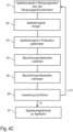
- Figure 4A shows how the painting robot 11 positions the print head 1 in a cleaning position above the cleaning device 4.
- the print head 1 In this cleaning position, the print head 1 is located directly above the cleaning device 4 or even in direct contact with it.
- the outlet nozzles of the print head 1 can be cleaned by a cleaning fluid that is sprayed from the inside against the outlet nozzles.
- Figure 4B shows, however, how the painting robot 11 positions the print head 1 in a test position in which the print head 1 is lifted from the cleaning device 4.
- the coating agent jets 2 still enter completely into the insertion opening 3 of the cleaning device 4, without the outer surfaces of the cleaning device 4 being contaminated by the coating agent jets 2.
- the camera 9 can then measure the coating agent jets 2, as already explained above.
- a first step S1 the print head 1 is moved into the cleaning position according to Figure 4A emotional.
- step S2 the print head 1 is then cleaned in the cleaning position by the cleaning device 4.
- the painting robot 11 then moves the print head 1 in a step S3 into a test position, which is in Figure 4B is shown.
- a step S4 the print head 1 then ejects the coating agent jets 2.
- a step S5 the coating agent jets 2 are then measured by the camera 9.
- steps S1-S6 are repeated with renewed cleaning.
- the print head 1 is ready for normal application of the coating agent in a step S7.
- Figure 5 shows a modification of the exemplary embodiment Figure 1 , so to avoid repetitions refer to the above description Figure 1 we referred, whereby the same reference numbers are used for corresponding details.
- FIG 6 shows a schematic representation of a coating system according to the invention with a cleaning device 12, which is controlled by a higher-level controller 14 via a solenoid valve cabinet 13. Furthermore shows Figure 5 a painting robot 15, which guides an application device and is controlled by the controller 14.
- the drawing shows a beam testing device 16, which is used to measure the coating agent jets that are emitted by the application device, as described above.
Description
Die Erfindung betrifft ein Reinigungsgerät zum Reinigen eines Applikationsgeräts (z.B. Druckkopf oder nicht zerstäubendes Applikationsgerät), das im Betrieb mehrere Beschichtungsmittelstrahlen eines Beschichtungsmittels (z.B. Lack, Klebstoff, Dichtmasse) auf ein Bauteil (z.B. Kraftfahrzeugkarosseriebauteil) appliziert. Weiterhin umfasst die Erfindung ein Betriebsverfahren für ein solches Reinigungsgerät.The invention relates to a cleaning device for cleaning an application device (e.g. print head or non-atomizing application device) which, during operation, applies several coating agent jets of a coating agent (e.g. paint, adhesive, sealant) to a component (e.g. motor vehicle body component). The invention further includes an operating method for such a cleaning device.
In modernen Lackieranlagen zur Lackierung von Kraftfahrzeugkarosseriebauteilen werden als Applikationsgerät üblicherweise Rotationszerstäuber eingesetzt, die das zu applizierende Beschichtungsmittel zerstäuben und eine Sprühwolke des Beschichtungsmittels abgeben. Bei einem Farbwechsel oder in Betriebspausen (z.B. bei einem Schichtwechsel oder am Wochenende) müssen diese Rotationszerstäuber außen und innen gereinigt werden, um Kontaminationen mit Farbresten oder Anhaftungen von Farbresten zu vermeiden. Hierzu sind aus dem Stand der Technik Reinigungsgeräte bekannt, die beispielsweise in
Nachteilig an den bekannten Rotationszerstäubern ist jedoch die Tatsache, dass der Auftragswirkungsgrad nicht 100% ist, so dass ein Teil des applizierten Lacks als Overspray entsorgt werden muss.However, the disadvantage of the known rotary atomizers is the fact that the application efficiency is not 100%, so that part of the applied paint has to be disposed of as overspray.
Zur Vermeidung dieses Problems sieht eine neuere Entwicklungslinie vor, dass als Applikationsgeräte anstelle von Rotationszerstäubern sogenannte Druckköpfe verwendet werden, wie sie beispielsweise in
Problematisch an derartigen Druckköpfen ist jedoch die Tatsache, dass die Düsen der Druckköpfe im Betrieb zusetzen können, was zu einer Fehlfunktion führt. Aus
Nachteilig an dem Stand der Technik ist also die Tatsache, dass die bekannten Reinigungsgeräte für Rotationszerstäuber konzipiert sind und sich deshalb nicht für Druckköpfe eignen. Ein weiterer Nachteil des Standes der Technik besteht darin, dass die Reinigung der Druckköpfe einerseits und die Prüfung der Beschichtungsmittelstrahlen andererseits bisher in getrennten Geräten erfolgen muss.The disadvantage of the prior art is the fact that the known cleaning devices are designed for rotary atomizers and are therefore not suitable for print heads. Another disadvantage of the prior art is that the cleaning of the print heads on the one hand and the testing of the coating agent jets on the other hand have previously had to be carried out in separate devices.
Ferner ist zum allgemeinen technischen Hintergrund der Erfindung hinzuweisen auf
Schließlich offenbart
Der Erfindung liegt deshalb die Aufgabe zugrunde, dieses Problem zu lösen.The invention is therefore based on the object of solving this problem.
Diese Aufgabe wird durch ein erfindungsgemäßes Reinigungsgerät gemäß dem Hauptanspruch und ein entsprechendes Betriebsverfahren gelöst.This object is achieved by a cleaning device according to the invention according to the main claim and a corresponding operating method.
Die Erfindung umfasst die allgemeine technische Lehre, ein Reinigungsgerät für ein Applikationsgerät (z.B. Druckkopf) und eine Strahlprüfungseinrichtung in einer einzigen baulichen Einheit zu integrieren. Dies bietet zunächst den Vorteil, dass für die Strahlprüfung und für die Reinigung nur ein einziges Gerät erforderlich ist. Ein weiterer Vorteil besteht darin, dass auf eine von zwei Auffangvorrichtungen für Lackreste verzichtet werden kann, da ansonsten bei separaten Geräten jeweils eine Auffangvorrichtung für das Reinigungsgerät und für die Strahlprüfungseinrichtung erforderlich ist. Darüber hinaus ermöglicht die Erfindung eine zentrale Lösung für Lackierkabinen und einen vollständigen Verzicht auf eine Auswaschung bzw. eine Trockenabscheidung.The invention includes the general technical teaching of integrating a cleaning device for an application device (e.g. print head) and a jet testing device in a single structural unit. This initially offers the advantage that only a single device is required for blast testing and cleaning. Another advantage is that one of two collecting devices for paint residues can be dispensed with, since otherwise, with separate devices, a collecting device is required for the cleaning device and for the jet testing device. In addition, the invention enables a central solution for painting booths and a complete elimination of leaching or dry separation.
Hinsichtlich der konstruktiven Merkmale des Reinigungsgeräts kann teilweise auf den Stand der Technik zurückgegriffen werden, so dass beispielsweise auf
Hinsichtlich der konstruktiven Gestaltung der Strahlprüfungseinrichtung kann ebenfalls teilweise auf den Stand der Technik verwiesen werden, wie er beispielsweise in
In einem bevorzugten Ausführungsbeispiel der Erfindung handelt es sich bei dem zu reinigenden und zu vermessenden Applikationsgerät um einen Druckkopf, wie er beispielsweise aus
Hierbei ist zu erwähnen, dass die Beschichtungsmittelstrahlen wahlweise aus einzelnen, getrennten Beschichtungsmitteltropfen oder aus einer Abfolge von Beschichtungsmitteltropfen bestehen können. Alternativ besteht die Möglichkeit, dass die einzelnen Beschichtungsmittelstrahlen in Strahllängsrichtung zusammenhängen, wobei diese Alternativen aus dem eingangs zitierten Stand der Technik bekannt sind und deshalb nicht näher beschrieben werden müssen.It should be mentioned here that the coating agent jets can optionally consist of individual, separate coating agent drops or of a sequence of coating agent drops. Alternatively, there is the possibility that the individual coating agent jets are connected in the longitudinal direction of the jet, although these alternatives are known from the prior art cited at the beginning and therefore do not need to be described in more detail.
Gemäß der Erfindung weist die Strahlprüfungseinrichtung zur Erfassung der Beschichtungsmittelstrahlen einen Sensor auf, insbesondere einen optischen Sensor, wie eine Kamera oder eine Hochgeschwindigkeitskamera.According to the invention, the beam testing device for detecting the coating agent jets has a sensor, in particular an optical sensor, such as a camera or a high-speed camera.
Bei der Überprüfung der Beschichtungsmittelstrahlen mittels eines optischen Sensors weist die Strahlprüfungseinrichtung eine Beleuchtungsquelle, vorzugsweise eine Gegenlichtquelle auf, die einen Lichtstrahl auf den optischen Sensor abgibt, wobei die zu überprüfende Beschichtungsmittelstrahlen im Strahlengang des Lichtstrahls zwischen der Gegenlichtquelle und dem optischen Sensor verläuft, so dass der optische Sensor die Beschichtungsmittelstrahlen im Gegenlicht prüft.When checking the coating agent jets using an optical sensor Beam testing device has an illumination source, preferably a backlight source, which emits a light beam onto the optical sensor, the coating agent rays to be checked running in the beam path of the light beam between the backlight source and the optical sensor, so that the optical sensor checks the coating agent rays in the backlight.
Bei dem bevorzugten Ausführungsbeispiel der Erfindung verläuft der Lichtstrahl der Gegenlichtquelle quer (z.B. rechtwinklig, orthogonal) zu den zu prüfenden Beschichtungsmittelstrahlen. Dabei verläuft der Lichtstrahl der Gegenlichtquelle quer, insbesondere im Wesentlichen rechtwinklig, zu der Strahlebene.In the preferred embodiment of the invention, the light beam from the backlight source runs transversely (e.g. at right angles, orthogonally) to the coating agent beams to be tested. The light beam from the backlight source runs transversely, in particular essentially at right angles, to the beam plane.
In einem anderen Ausführungsbeispiel verläuft der Lichtstrahl der Gegenlichtquelle tangential, insbesondere im Wesentlichen im Winkel von 0°, zu der Strahlebene.In another exemplary embodiment, the light beam from the backlight source runs tangentially, in particular essentially at an angle of 0°, to the beam plane.
Es ist auch möglich, beide Ausrichtungen der Gegenlichtquelle zur Strahlebene nacheinander zu prüfen. Dazu muss entweder die Öffnung im Reinigungsgerät groß genug sein, um die Strahlen bei beiden Ausrichtungen aufnehmen zu können oder es müssen zwei separate Öffnungen mit unterschiedlicher Ausrichtung vorhanden sein. Des Weiteren ist es möglich, die Auffangvorrichtung beweglich, insbesondere drehbar auszuführen um die unterschiedlichen Ausrichtungen der Strahlebene prüfen zu können.It is also possible to check both alignments of the backlight source to the beam plane one after the other. To do this, either the opening in the cleaning device must be large enough to accommodate the beams in both orientations or there must be two separate openings with different orientations. Furthermore, it is possible to make the collecting device movable, in particular rotatable, in order to be able to check the different orientations of the jet plane.
Weiterhin ist zu erwähnen, dass das Applikationsgerät (z.B. Druckkopf) typischerweise mehrere parallele Beschichtungsmittelstrahlen abgibt, die in einer gemeinsamen Strahlebene liegen. Hierbei ist der Lichtstrahl der Gegenlichtquelle vorzugsweise quer (z.B. rechtwinklig, orthogonal) zu der Strahlebene der Beschichtungsmittelstrahlen ausgerichtet.It should also be mentioned that the application device (e.g. print head) typically emits several parallel jets of coating agent that lie in a common jet plane. Here, the light beam from the backlight source is preferably aligned transversely (e.g. at right angles, orthogonally) to the beam plane of the coating agent jets.
Weiterhin ist zu erwähnen, dass die Strahlprüfungseinrichtung vorzugsweise einen optischen Diffusor aufweist, der im Strahlengang der Gegenlichtquelle zwischen der Gegenlichtquelle und den zu prüfenden Beschichtungsmittelstrahlen angeordnet ist, so dass das Gegenlicht diffus ist.Furthermore, it should be mentioned that the beam testing device preferably has an optical diffuser which is arranged in the beam path of the backlight source between the backlight source and the coating agent jets to be tested, so that the backlight is diffuse.
Der Diffusor kann beispielsweise ortsfest angeordnet sein, so dass in jedem Betriebszustand diffuses Gegenlicht verwendet wird. Es ist jedoch alternativ auch möglich, dass der Diffusor beweglich angeordnet ist und wahlweise in den Strahlengang der Gegenlichtquelle hinein oder aus dem Strahlengang der Gegenlichtquelle heraus bewegt werden kann, um das Gegenlicht wahlweise diffus oder in gebündelter Form zu liefern.The diffuser can, for example, be arranged in a stationary manner, so that diffuse backlight is used in every operating state. However, it is alternatively also possible for the diffuser to be arranged to be movable and to be able to be moved either into the beam path of the backlight source or out of the beam path of the backlight source in order to selectively illuminate the backlight to be delivered diffusely or in bundled form.
Darüber hinaus ist zu erwähnen, dass die Strahlprüfungseinrichtung die Beschichtungsmittelstrahlen vorzugsweise in einem bestimmten Überprüfungsbereich (ROI: Region of Interest) überprüft, wobei der räumlich begrenzte Überprüfungsbereich vorzugsweise unmittelbar nach dem Austritt aus dem Applikationsgerät liegt, d.h. unmittelbar vor den Düsenöffnungen des Applikationsgeräts, zum Beispiel in einem Abstand von 0-100mm, speziell von 0-70mm, insbesondere von 0-40mm. Darüber hinaus ist eine Auswertungseinheit vorgesehen, die eingangsseitig mit dem Sensor verbunden ist und aus dem Sensorsignal mindestens eine der folgenden Größen ermittelt:
- Parallelität der Beschichtungsmittelstrahlen relativ zueinander. Dies kann ebenfalls sinnvoll sein, um beispielsweise ein Zusetzen der Beschichtungsmitteldüsen des Druckkopfs zu erkennen, da die Beschichtungsmittelstrahlen dann - wie bereits vorstehend erwähnt - leicht schräg austreten können.
- Verzögerungszeit der einzelnen Beschichtungsmittelstrahlen zwischen einem Ventilöffnungsbefehl und der anschließenden Erfassung des zugehörigen Beschichtungsmittelstrahls, wobei die Verzögerungszeit individuell für die einzelnen Beschichtungsmittelstrahlen ermittelt wird. Bei der Ansteuerung der einzelnen Ventile für die einzelnen Beschichtungsmitteldüsen des Druckkopfs kann diese individuelle Verzögerungszeit dann kompensatorisch berücksichtigt werden.
- Parallelism of the coating agent jets relative to each other. This can also be useful, for example, to detect clogging of the coating agent nozzles of the print head, since the coating agent jets can then - as already mentioned above - emerge slightly at an angle.
- Delay time of the individual coating agent jets between a valve opening command and the subsequent detection of the associated coating agent jet, the delay time being determined individually for the individual coating agent jets. When controlling the individual valves for the individual coating agent nozzles of the print head, this individual delay time can then be taken into account in a compensatory manner.
Darüber hinaus kann die Auswertungseinheit zusätzlich mindestens eine der folgenden Größen ermitteln:
- Größe der einzelnen Beschichtungsmitteltropfen des Beschichtungsmittelstrahls.
- Abstand der benachbarten Beschichtungsmitteltropfen entlang dem Beschichtungsmittelstrahl.
- Anzahl der Beschichtungsmittelstrahlen, die aus dem Applikationsgerät austreten. Auf diese Weise kann beispielsweise das Zusetzen einer Beschichtungsmitteldüse erkannt werden, wenn die Anzahl der ermittelten Beschichtungsmittelstrahlen nicht der Anzahl der Beschichtungsmitteldüsen entspricht.
- Austrittswinkel der Beschichtungsmittelstrahlen. Auf diese Weise kann ein beginnendes Zusetzen einer Beschichtungsmitteldüse erkannt werden, da sich dies oftmals in einem leicht schrägen Austreten des jeweiligen Beschichtungsmittelstrahls äußert.
- Zerfallslänge der Beschichtungsmittelstrahlen, wobei die Zerfallslänge die Länge der zunächst zusammenhängenden Beschichtungsmittelstrahlen ist, ab der die Beschichtungsmittelstrahlen in einzelne Beschichtungsmitteltropfen zerfällt. Dies kann ebenfalls sinnvoll sein, um beispielsweise eine beginnende Verstopfung der Beschichtungsmitteldüsen des Druckkopfs zu erkennen, da ein Zusetzen der Beschichtungsmitteldüsen in einer geringeren Zerfallslänge resultieren.
- Size of the individual coating agent drops of the coating agent jet.
- Distance of the neighboring coating agent drops along the coating agent jet.
- Number of coating agent jets emerging from the application device. In this way, for example, the clogging of a coating agent nozzle can be detected if the number of coating agent jets determined does not correspond to the number of coating agent nozzles.
- Exit angle of the coating agent jets. In this way, the beginning of clogging of a coating agent nozzle can be detected, since this often manifests itself in a slightly oblique exit of the respective coating agent jet.
- Decay length of the coating agent jets, whereby the decay length is the length of the initially connected coating agent jets, from which the coating agent jets disintegrate into individual coating agent drops. This can also be useful, for example, to detect the beginning of clogging of the coating agent nozzles of the print head, since clogging of the coating agent nozzles results in a shorter decay length.
Hinsichtlich der konstruktiven Gestaltung des Reinigungsgeräts ist zu erwähnen, dass das Reinigungsgerät vorzugsweise einen Reinigungsbehälter aufweist, um das Applikationsgerät oder zumindest die von dem Applikationsgerät abgegebenen Beschichtungsmittelstrahlen während einer Reinigung aufzunehmen. Der Reinigungsbehälter weist vorzugsweise eine Einführöffnung auf, die vorzugsweise an der Oberseite des Reinigungsbehälters angeordnet ist, um das zu reinigende Applikationsgerät oder zumindest die von dem Applikationsgerät abgegebenen Beschichtungsmittelstrahlen aufzunehmen. Die Einführöffnung ist vorzugsweise hinreichend groß, um alle Beschichtungsmittelstrahlen des Applikationsgeräts aufnehmen zu können, ohne dass die Beschichtungsmittelstrahlen die Außenfläche des Reinigungsgeräts verschmutzen.With regard to the structural design of the cleaning device, it should be mentioned that the cleaning device preferably has a cleaning container in order to accommodate the application device or at least the coating agent jets emitted by the application device during cleaning. The cleaning container preferably has an insertion opening, which is preferably arranged on the top of the cleaning container in order to receive the application device to be cleaned or at least the coating agent jets emitted by the application device. The insertion opening is preferably sufficiently large to be able to accommodate all of the coating agent jets from the application device without the coating agent jets contaminating the outer surface of the cleaning device.
In einer besonderen Ausführungsform hat das Reinigungsgerät mindestens eine weitere Öffnung, in die das Applikationsgerät den Lack während der Messung abgibt, d.h. eine Öffnung für den Reinigungsvorgang und mindestens eine zusätzliche Öffnung für den Vorgang der Strahlprüfung.In a special embodiment, the cleaning device has at least one further opening into which the application device dispenses the paint during the measurement, i.e. one opening for the cleaning process and at least one additional opening for the jet testing process.
In dem Reinigungsbehälter ist vorzugsweise mindestens eine Reinigungsdüse angeordnet, um das Applikationsgerät von außen mit einem Reinigungsfluid zu besprühen. Beispielsweise kann es sich bei dem Reinigungsfluid um ein Spülmittel für wasserbasierte Fluide oder für Fluide auf Basis organischer Lösemittel handeln. Darunter fallen auch Gemische, die neben Wasser und/oder organischen Lösemitteln auch andere Substanzen enthalten, wie z.B. Netzmittel, Co-Löser oder andere Additive. Die Reinigungsdüse kann in dem Reinigungsbehälter ortsfest angeordnet sein. Vorzugsweise ist die mindestens eine Reinigungsdüse jedoch in dem Reinigungsbehälter beweglich angeordnet, beispielsweise drehbar oder schwenkbar, wodurch sich die Reinigungswirkung verbessern lässt. Die Reinigungsdüse kann aber auch zum Beispiel mittels eines Zylinders linear (vor- und zurück) bewegt werden. An seiner Unterseite kann der Reinigungsbehälter eine Abführung aufweisen, um Reste des Beschichtungsmittels und des Reinigungsmittels in eine Rückführung ableiten zu können. Weiterhin ist zu erwähnen, dass in dem Reinigungsbehälter vorzugsweise mindestens eine Reinigungsdüse angeordnet ist, um das Applikationsgerät von außen mit einem Trocknungsgas (z.B. Druckluft) anzublasen. Die Trocknungsdüse kann ähnlich der Reinigungsdüse drehbar oder schwenkbar gelagert sein oder linear (vor- und zurück) bewegt werden.At least one cleaning nozzle is preferably arranged in the cleaning container in order to spray the application device from the outside with a cleaning fluid. For example, the cleaning fluid can be a rinsing agent for water-based fluids or for fluids based on organic solvents. This also includes mixtures that, in addition to water and/or organic solvents, also contain other substances, such as wetting agents, co-solvents or others Additives. The cleaning nozzle can be arranged stationary in the cleaning container. Preferably However, the at least one cleaning nozzle is movably arranged in the cleaning container, for example rotatable or pivotable, which can improve the cleaning effect. The cleaning nozzle can also be moved linearly (back and forth) using a cylinder, for example. The cleaning container can have a discharge on its underside in order to be able to drain away residues of the coating agent and the cleaning agent into a return system. Furthermore, it should be mentioned that at least one cleaning nozzle is preferably arranged in the cleaning container in order to blow the application device from the outside with a drying gas (eg compressed air). The drying nozzle can be mounted rotatably or pivotally, similar to the cleaning nozzle, or can be moved linearly (back and forth).
Die Reinigungsdüse gibt vorzugsweise einen Flachstrahl des Reinigungsmittels aus einer im Wesentlichen linienförmigen Düsenanordnung ab, beispielsweise aus einer Schlitzdüse oder aus zahlreichen Austrittsdüsen, die in einer Düsenreihe angeordnet sind. Das Applikationsgerät kann ebenfalls mehrere Applikationsdüsen aufweisen, die in einer Düsenreihe angeordnet sind. Hierbei ist es vorteilhaft, wenn die linienförmige Düsenanordnung der Reinigungsdüsen im Wesentlichen parallel zu der Düsenreihe der Applikationsdüsen ausgerichtet ist. Der Flachstrahl des Reinigungsmittels trifft dabei vorzugsweise schräg von unten, in einem Winkel von 5-45°, insbesondere 15-35°, bezogen auf die Strahlrichtung der Applikationsdüsen, auf die Düsenreihe der Applikationsdüsen auf. Hierbei ist es vorteilhaft, wenn der Auftreffpunkt des Reinigungsmittels nicht direkt auf die Applikationsdüsen gerichtet ist, um einen Eintrag von Reinigungsmittel in die Applikationsdüsen bzw. ein Ausspülen von Lack aus den Applikationsdüsen zu verhindern.The cleaning nozzle preferably emits a flat jet of cleaning agent from a substantially linear nozzle arrangement, for example from a slot nozzle or from numerous outlet nozzles which are arranged in a row of nozzles. The application device can also have several application nozzles that are arranged in a row of nozzles. It is advantageous here if the linear nozzle arrangement of the cleaning nozzles is aligned essentially parallel to the row of nozzles of the application nozzles. The flat jet of the cleaning agent preferably hits the row of nozzles of the application nozzles obliquely from below, at an angle of 5-45°, in particular 15-35°, based on the jet direction of the application nozzles. It is advantageous here if the point of impact of the cleaning agent is not directed directly at the application nozzles in order to prevent cleaning agent from entering the application nozzles or rinsing out paint from the application nozzles.
Zu der Trocknungsdüse ist zu erwähnen, dass diese ebenfalls ortsfest oder beweglich sein kann. Bei einer beweglichen Anordnung der Trocknungsdüse kann diese beispielsweise von einem pneumatischen Linearzylinder bewegt werden. Auch die Trocknungsdüse gibt das Trocknungsgas vorzugsweise in Form eines Flachstrahls aus einer im Wesentlichen linienförmigen Düsenanordnung ab, insbesondere aus einer Schlitzdüse oder aus zahlreichen Austrittsdüsen, die in einer Düsenreihe angeordnet sind. Hierbei ist die linienförmige Düsenanordnung der Trocknungsdüsen vorzugsweise quer zu der Düsenreihe der Applikationsdüsen ausgerichtet.Regarding the drying nozzle, it should be mentioned that it can also be stationary or movable. With a movable arrangement of the drying nozzle, it can be moved, for example, by a pneumatic linear cylinder. The drying nozzle also emits the drying gas, preferably in the form of a flat jet from a substantially linear nozzle arrangement, in particular from a slot nozzle or from numerous outlet nozzles which are arranged in a row of nozzles. Here, the linear nozzle arrangement of the drying nozzles is preferably aligned transversely to the row of nozzles of the application nozzles.
Darüber hinaus kann das Reinigungsgerät eine Feuchthaltevorrichtung aufweisen, um die Austrittsdüsen des Applikationsgeräts feucht zu halten. Eine solche Feuchthaltevorrichtung kann beispielsweise eine Wanne, ein Vlies, einen Schwamm und/oder ein poröses Material aufweisen, die mit einem Lösemittel getränkt sind oder von dem Lösemittel durchströmt werden. Beispielsweise kann die Feuchthaltevorrichtung auch eine Zuleitung und/oder eine Abführung für das Lösemittel aufweisen.In addition, the cleaning device can have a moisturizing device to keep the outlet nozzles of the application device moist. Such a moisturizing device can, for example, have a tub, a fleece, a sponge and/or a porous material are soaked with a solvent or have the solvent flowing through them. For example, the moisturizing device can also have a supply line and/or an outlet for the solvent.
Ferner ist zu erwähnen, dass die Erfindung nicht nur Schutz beansprucht für das erfindungsgemäße Reinigungsgerät mit der integrierten Strahlprüfungseinrichtung. Vielmehr beansprucht die Erfindung auch Schutz für eine erfindungsgemäße Beschichtungsanlage mit dem erfindungsgemä-ßen Reinigungsgerät sowie mit einem mehrachsigen Applikationsroboter zum Bewegen des Applikationsgeräts und einer Steuerung, wobei die Steuerung sowohl den Applikationsroboter als auch das Reinigungsgerät und die Strahlprüfungseinrichtung steuert. Hierbei ist es möglich, dass die Beschichtungsanlage eine Lackierkabine ohne eine Auswaschung und ohne eine Trockenabscheidung aufweist.Furthermore, it should be mentioned that the invention does not only claim protection for the cleaning device according to the invention with the integrated beam testing device. Rather, the invention also claims protection for a coating system according to the invention with the cleaning device according to the invention and with a multi-axis application robot for moving the application device and a control, the control controlling both the application robot and the cleaning device and the beam testing device. It is possible for the coating system to have a painting booth without washing out and without dry deposition.
Schließlich beansprucht die Erfindung auch Schutz für ein entsprechendes Betriebsverfahren, wobei sich die einzelnen Schritte des erfindungsgemäßen Betriebsverfahrens bereits aus der vorangehenden Beschreibung ergeben, so dass auf eine separate Beschreibung des erfindungsgemäßen Betriebsverfahrens verzichtet werden kann.Finally, the invention also claims protection for a corresponding operating method, the individual steps of the operating method according to the invention already emerging from the preceding description, so that a separate description of the operating method according to the invention can be dispensed with.
Es ist jedoch zu erwähnen, dass es im Rahmen des erfindungsgemäßen Betriebsverfahrens möglich ist, dass mehrfach hintereinander eine Reinigung und eine Strahlvermessung erfolgt. Die Reinigung des Applikationsgeräts (z.B. Druckkopf) wird dann so lange wiederholt, bis die anschließende Strahlüberprüfung der applizierten Beschichtungsmittelstrahlen ergibt, dass eine ordnungsgemäße Strahlabgabe erfolgt. Bei dieser zyklischen Wiederholung von Reinigung und Strahlvermessung ist es möglich, dass zunehmend intensivere Reinigungsprogramme verwendet werden.However, it should be mentioned that within the scope of the operating method according to the invention it is possible for cleaning and beam measurement to take place several times in succession. The cleaning of the application device (e.g. print head) is then repeated until the subsequent jet check of the applied coating agent jets shows that the jet is being emitted properly. With this cyclical repetition of cleaning and jet measurement, it is possible that increasingly intensive cleaning programs are used.
Andere vorteilhafte Weiterbildungen der Erfindung sind in den Unteransprüchen gekennzeichnet und werden nachstehend zusammen mit der Beschreibung der bevorzugten Ausführungsbeispiele anhand der Figuren näher erläutert. Es zeigen:
Figur 1- eine schematische Darstellung eines erfindungsgemäßen Reinigungsgeräts mit einer integrierten Strahlprüfungseinrichtung,
Figur 2- eine andere schematische Darstellung des Reinigungsgeräts gemäß
Figur 1 , Figur 3- eine vereinfachte Aufsicht auf die Einführöffnung des Reinigungsgeräts gemäß
den Figuren 1 und2 , - Figur 4A
- eine schematische Darstellung eines erfindungsgemäßen Reinigungsgeräts, wobei ein Roboter einen Druckkopf in einer Reinigungsposition positioniert,
- Figur 4B
- eine Abwandlung von
Figur 4A , wobei der Roboter den Druckkopf in einer Prüfposition positioniert, - Figur 4C
- das Betriebsverfahren des Reinigungsgeräts gemäß den
Figuren 4A-4B in Form eines Flussdiagramms, Figur 5- eine schematische Darstellung einer Abwandlung des Reinigungsgeräts gemäß Figur 1, sowie
Figur 6- eine schematische Darstellung einer erfindungsgemäßen Beschichtungsanlage.
- Figure 1
- a schematic representation of a cleaning device according to the invention with an integrated beam testing device,
- Figure 2
- another schematic representation of the cleaning device according to
Figure 1 , - Figure 3
- a simplified supervision of the insertion opening of the cleaning device according to
Figures 1 and2 , - Figure 4A
- a schematic representation of a cleaning device according to the invention, wherein a robot positions a print head in a cleaning position,
- Figure 4B
- a variation of
Figure 4A , where the robot positions the print head in a test position, - Figure 4C
- the operating procedure of the cleaning device in accordance with the
Figures 4A-4B in the form of a flowchart, - Figure 5
- a schematic representation of a modification of the cleaning device according to Figure 1, and
- Figure 6
- a schematic representation of a coating system according to the invention.
In der Zeichnung werden die Beschichtungsmittelstrahlen 2 in eine Einführöffnung 3 eines Reinigungsgeräts 4 abgegeben, wobei das Reinigungsgerät 4 hierbei nur schematisch dargestellt ist.In the drawing, the
Das Reinigungsgerät 4 verfügt an seiner Unterseite über einen Ablauf 5 zum Abführen von Resten von Beschichtungsmittel und Spülmittel.The
In dem Reinigungsgerät 4 kann der Druckkopf 1 gereinigt werden. Hierzu wird der Druckkopf 1 auf das Reinigungsgerät 4 abgesenkt, wie noch detailliert beschrieben wird.The
In
Die Strahlprüfungseinrichtung weist zunächst eine Gegenlichtquelle 6 auf, die einen Lichtstrahl 7 durch einen Diffusor 8 leitet, so dass die Beschichtungsmittelstrahlen 2 mit einem diffusen Gegenlicht beleuchtet werden.The beam testing device initially has a
Weiterhin umfasst die Strahlprüfungseinrichtung eine Kamera 9, die im Strahlengang des Lichtstrahls 7 der Gegenlichtquelle 6 hinter den Beschichtungsmittelstrahlen 2 angeordnet ist und die Beschichtungsmittelstrahlen 2 vermisst.Furthermore, the beam testing device comprises a
Der Lichtstrahl 7 der Gegenlichtquelle verläuft hierbei in einem Winkel β=90° zu den Beschichtungsmittelstrahlen 2 und in einem Winkel α=90° zur Düsenreihe in dem Druckkopf 1.The
Das Bildsignal der Kamera 9 wird dann an eine Auswertungseinheit 10 weitergeleitet, die das Bildsignal auswertet und beispielsweise die Anzahl der Beschichtungsmittelstrahlen 2, den Austrittswinkel der Beschichtungsmittelstrahlen 2, die Zerfallslänge der Beschichtungsmittelstrahlen 2 und andere Größen ermitteln kann.The image signal from the
Hierbei ist zu erwähnen, dass die Strahlprüfungseinrichtung in der Zeichnung getrennt von dem Reinigungsgerät 4 gezeichnet ist. Dies dient jedoch nur zur Veranschaulichung der Funktionsweise der Strahlprüfungseinrichtung. Tatsächlich bilden die Strahlprüfungseinrichtung und das Reinigungsgerät 4 eine bauliche Einheit.It should be mentioned here that the beam testing device is drawn separately from the
Die
Im Folgenden wird nun das Ausführungsbeispiel gemäß den
Aus den
Im Folgenden wird nun das Flussdiagramm gemäß
In einem ersten Schritt S1 wird der Druckkopf 1 in die Reinigungsposition gemäß
In einem folgenden Schritt S2 wird der Druckkopf 1 dann in der Reinigungsposition von dem Reinigungsgerät 4 gereinigt.In a subsequent step S2, the
Anschließend bewegt der Lackierroboter 11 dann den Druckkopf 1 in einem Schritt S3 in eine Prüfposition, die in
In einem Schritt S4 stößt der Druckkopf 1 dann die Beschichtungsmittelstrahlen 2 aus.In a step S4, the
In einem Schritt S5 werden die Beschichtungsmittelstrahlen 2 dann von der Kamera 9 vermessen.In a step S5, the
Falls die Auswertung in einem folgenden Schritt S7 dann ergibt, dass die Beschichtungsmittelstrahlen 2 nicht ordnungsgemäß abgegeben werden, so werden die Schritte S1-S6 mit einer erneuten Reinigung wiederholt.If the evaluation in a subsequent step S7 then shows that the
Falls die Auswertung dagegen ergibt, dass die Beschichtungsmittelstrahlen 2 ordnungsgemäß abgegeben werden, so ist der Druckkopf 1 in einem Schritt S7 bereit zur normalen Applikation des Beschichtungsmittels.If, on the other hand, the evaluation shows that the
Eine Besonderheit dieses Ausführungsbeispiels besteht darin, dass der Lichtstrahl 7 der Gegenlichtquelle 6 mit einem Winkel α=0° in der Strahlebene Beschichtungsmittelstrahlen 2 verläuft.A special feature of this exemplary embodiment is that the
Schließlich zeigt die Zeichnung noch eine Strahlprüfungseinrichtung 16, die zur Vermessung der Beschichtungsmittelstrahlen dient, die von dem Applikationsgerät abgegeben werden, wie vorstehend beschrieben wurde.Finally, the drawing shows a
Die gestrichelte Linie verdeutlicht hierbei, dass die Strahlprüfungseinrichtung 16 und das Reinigungsgerät 12 eine bauliche Einheit bilden.The dashed line makes it clear that the
Hierbei ist zu erwähnen, dass die Steuerung sowohl das Reinigungsgerät 12 als auch die Strahlprüfungseinrichtung 16 und den Lackierroboter 15 ansteuert.It should be mentioned here that the control controls both the
- 11
- DruckkopfPrinthead
- 22
- BeschichtungsmittelstrahlenCoating agent blasting
- 33
- Einführöffnung der ReinigungsvorrichtungInsertion opening of the cleaning device
- 44
- Reinigungsgerätscleaning device
- 55
- AblaufSequence
- 66
- GegenlichtquelleBacklight source
- 77
- Lichtstrahl der GegenlichtquelleLight beam from the backlight source
- 88th
- Diffusordiffuser
- 99
- Kameracamera
- 1010
- AuswertungseinheitEvaluation unit
- 1111
- LackierroboterPainting robots
- 1212
- ReinigungsgerätCleaning device
- 1313
- MagnetventilschrankSolenoid valve cabinet
- 1414
- Steuerungsteering
- 1616
- StrahlprüfungseinrichtungBeam testing facility
- αα
- Winkel α=90° bzw. α=0° zwischen dem Lichtstrahl der Gegenlichtquelle und der Ebene der BeschichtungsmittelstrahlenAngle α=90° or α=0° between the light beam of the backlight source and the plane of the coating agent jets
- ββ
- Winkel β=90° zwischen dem Lichtstrahl der Gegenlichtquelle und der Düsenreihe der BeschichtungsmitteldüsenAngle β=90° between the light beam of the backlight source and the row of nozzles of the coating agent nozzles
Claims (13)
- Cleaning device (4; 12) for cleaning an application device (1) which, in operation, applies coating agent jets (2) of a coating agent to a component, witha) a jet checking device (6-10; 16) integrated in the cleaning device (4; 12) in order to check the coating agent jets (2) emitted by the application device (1), so that the cleaning device (4; 12) forms a structural unit with the jet checking device (6-10; 16),b) wherein the jet checking device (6-10; 16) comprises a sensor (9) for detecting the coating agent jets (2),c) wherein the jet checking device (6-10; 16) comprises an evaluation unit (10) which is connected at the input side to the sensor (9),
characterized ind) that the evaluation unit (10) determines from the sensor signal at least one of the following variables:d1) parallelism of the coating agent jets (2) relative to each other,d2) delay time of the individual coating agent jets (2) between a valve opening command and the detection of the associated coating agent jet (2), the delay time being determined individually for the individual coating agent jets (2). - Cleaning device (4; 12) according to claim 1, characterized in that the jet checking device (6-10; 16) comprises a backlight source (6) which emits a light beam (7) onto the optical sensor (9), the coating agent jets (2) to be checked running in the beam path of the light beam (7) between the backlight source (6) and the optical sensor (9), so that the optical sensor (9) checks the coating agent jets (2) in the backlight.
- Cleaning device (4; 12) according to claim 2, characterized ina) that the light beam (7) of the backlight source (6) runs transversely, in particular essentially at right angles, to the coating agent jets (2) to be checked, and/orb) that the coating agent jets (2) run in a common jet plane, and/orc) that the light beam (7) of the back light source (6) runs transversely, in particular essentially at right angles, to the jet plane, and/ord) that the light beam (7) of the back light source (6) runs in the jet plane or at an acute angle to the jet plane, in particular at an angle (α) of less than 5°, 2° or 1° to the jet plane, and/ore) that the jet checking device (6-10; 16) has a diffuser (8) which is arranged in the beam path of the back light source (6) between the back light source (6) and the coating agent jets (2) to be checked, so that the back light is diffuse, and that the diffuser (8) is arranged movably and can be moved selectively into the beam path of the back light source (6) or out of the beam path of the back light source (6) in order to deliver the back light selectively in diffuse or bundled form.
- Cleaning device (4; 12) according to one of the preceding claims, characterized in that the jet checking device (6-10; 16d) checks the coating agent jets (2) in a specific checking area, in particular immediately after it emerges from the application device (1).
- Cleaning device (4; 12) according to one of the preceding claims, characterized ina) that the cleaning device (4; 12) comprises a cleaning container for receiving the application device (1) during cleaning, andb) that the cleaning container comprises an insertion opening (3), in particular on the upper side of the cleaning container, in order to receive the coating agent jets (2) and/or to be able to insert the application device (1) into the cleaning container for cleaning, andc) that at least one cleaning nozzle is arranged in the cleaning container for spraying the application device (1) from the outside with a cleaning fluid, andd) that the at least one cleaning nozzle is arranged stationary or movable, in particular rotatable, linear or pivotable, ande) that the cleaning container has a discharge (5) on its underside for discharging residues of the coating agent and cleaning agent, andf) that at least one drying nozzle is arranged in the cleaning container in order to blow a drying gas onto the application device (1) from the outside, andg) that the at least one drying nozzle is arranged stationary or movable, in particular rotatable, linear or pivotable.
- Cleaning device according to claim 5, characterized ina) that the cleaning container comprises a first insertion opening for receiving the at least one coating agent jet during cleaning of the application device, andb) that the cleaning container comprises a second insertion opening for receiving the at least one coating agent jet during jet checking.
- Cleaning device (4; 12) according to claim 5 or 6, characterized ina) that the cleaning nozzle emits a flat jet of the cleaning agent from a substantially linear nozzle arrangement, in particular from a slot nozzle or numerous outlet nozzles in a row of nozzles,b) that the application device (1) has a plurality of application nozzles arranged in a nozzle row,c) that the linear nozzle arrangement of the cleaning nozzles is aligned essentially parallel to the nozzle row of the application nozzles,d) that the flat jet of the cleaning agent is preferably directed obliquely from below onto the row of nozzles of the application nozzles, in particular at an angle of 5°-45° or 10°-30°, and/ore) that the flat jet of the cleaning agent is preferably not directed directly onto the application nozzles.
- Cleaning device (4; 12) according to claim 5, 6 or 7, characterized ina) that the drying nozzle is movable,b) that at least one pneumatic linear cylinder is preferably provided for moving the drying nozzle,c) that the drying nozzle preferably emits a flat jet of the drying gas from a substantially linear nozzle arrangement, in particular from a slot nozzle or numerous outlet nozzles in a row of nozzles,d) that the linear nozzle arrangement of the drying nozzles is preferably aligned transversely to the nozzle row of the application nozzles.
- Cleaning device (4; 12) according to one of the preceding claims, characterized ina) that the cleaning device (4; 12) has a moisture-retaining device for keeping the outlet nozzles of the application device (1) moist,b) that the moisture-retaining device preferably comprises a trough, a nonwoven fabric, a sponge and/or a porous material, which are impregnated with a solvent or through which the solvent flows,c) that the moisture-retaining device preferably comprises a supply line and/or a discharge line for the solvent.
- Cleaning device (4; 12) according to one of the preceding claims, characterized ina) that the application device (1) does not emit a spray mist of the coating agent, but a spatially narrowly limited coating agent jet (2), in particular with a jet widening angle of less than 10°, 5° or 2°, and/orb) that the application device (1) operates essentially without overspray, and/orc) that the application device (1) is a print head, and/ord) that the coating agent jet (2) consists of individual coating agent drops or a sequence of coating agent drops or is contiguous in the longitudinal direction of the jet.
- Coating installation for coating components, in particular motor vehicle body components, havinga) a multi-axis application robot (11) for moving the application device (1),b) the cleaning device (4; 12) according to one of the preceding claims, andc) a controller (14) which controls the application robot (11) and the cleaning device (4; 12) and the jet checking device (6-10; 16),d) wherein the coating apparatus preferably comprises a painting booth without washout and without dry cut-off.
- Operating method for a cleaning device (4; 12) for cleaning an application device (1), comprising the following steps:a) positioning the application device (1) in a cleaning position in or on the cleaning device (4; 12), in particular at a distance from the cleaning device (4; 12) of less than 10mm, 5mm or 1mm or with direct contact between the application device (1) and the cleaning device (4; 12), andb) cleaning of the application device (1) in the cleaning position by the cleaning device (4; 12),c) checking the coating agent jets (2) emitted by the application device (1) by means of a jet checking device (6-10; 16) integrated in the cleaning device (4; 12), wherein the jet checking device (6-10; 16) comprises a sensor (9) for detecting the coating agent jets (2) and an evaluation unit (10) which is connected at the input side to the sensor (9),
characterized ind) that the evaluation unit (10) determines from the sensor signal at least one of the following variables:d1) parallelism of the coating agent jets (2) relative to each other,d2) delay time of the individual coating agent jets (2) between a valve opening command and the detection of the associated coating agent jet (2), the delay time being determined individually for the individual coating agent jets (2). - Operating method according to claim 12, characterized by the following step:a) positioning the application device (1) in a checking position in or on the cleaning device (4; 12) for subsequent inspection of the coating agent jet (2), wherein the checking position is different from the cleaning position, and/ora1) that the checking position is above the cleaning position and the coating agent jets are delivered into the cleaning opening, and/ora2) that the at least one checking position is adjacent to the cleaning position and the coating agent jets are emitted into at least one additional opening,b) repeating the cleaning and the subsequent inspection until the checking shows that the jet delivery is proper, in particular with an increasing intensity of the cleaning.
Applications Claiming Priority (2)
| Application Number | Priority Date | Filing Date | Title |
|---|---|---|---|
| DE102018131380.2A DE102018131380A1 (en) | 2018-12-07 | 2018-12-07 | Cleaning device for an application device |
| PCT/EP2019/083642 WO2020115117A1 (en) | 2018-12-07 | 2019-12-04 | Cleaning device for an application device |
Publications (2)
| Publication Number | Publication Date |
|---|---|
| EP3890895A1 EP3890895A1 (en) | 2021-10-13 |
| EP3890895B1 true EP3890895B1 (en) | 2023-11-08 |
Family
ID=68841071
Family Applications (1)
| Application Number | Title | Priority Date | Filing Date |
|---|---|---|---|
| EP19817623.2A Active EP3890895B1 (en) | 2018-12-07 | 2019-12-04 | Cleaning device for an application device |
Country Status (9)
| Country | Link |
|---|---|
| US (1) | US20220040719A1 (en) |
| EP (1) | EP3890895B1 (en) |
| JP (1) | JP2022518341A (en) |
| KR (1) | KR20210102332A (en) |
| CN (1) | CN113165002A (en) |
| DE (1) | DE102018131380A1 (en) |
| MX (1) | MX2021006566A (en) |
| WO (1) | WO2020115117A1 (en) |
| ZA (1) | ZA202104708B (en) |
Families Citing this family (8)
| Publication number | Priority date | Publication date | Assignee | Title |
|---|---|---|---|---|
| FR3094899B1 (en) * | 2019-04-15 | 2022-10-07 | Exel Ind | Installation for applying coating product and method for cleaning such an installation |
| DE102019135360A1 (en) | 2019-12-20 | 2021-06-24 | Dürr Systems Ag | Cleaning device for cleaning a nozzle applicator and corresponding cleaning method |
| WO2022184226A1 (en) * | 2021-03-01 | 2022-09-09 | Abb Schweiz Ag | Method of monitoring cleaning of coating apparatus, method of cleaning coating apparatus, coating apparatuses, and robot system |
| FR3124589B1 (en) | 2021-06-28 | 2024-03-01 | Exel Ind | DROPLET ANALYSIS SYSTEM AND COATING INSTALLATION COMPRISING SUCH A SYSTEM |
| JP7122451B1 (en) | 2021-07-08 | 2022-08-19 | アーベーベー・シュバイツ・アーゲー | Coating determination device for coating head and coating system |
| DE102021133410A1 (en) | 2021-12-16 | 2023-06-22 | Dürr Systems Ag | Coating equipment and related operating procedure |
| DE102022100401A1 (en) * | 2022-01-10 | 2023-07-13 | Dürr Systems Ag | Application system and associated monitoring procedure |
| JP7241955B1 (en) * | 2022-12-20 | 2023-03-17 | アーベーベー・シュバイツ・アーゲー | painting machine |
Citations (2)
| Publication number | Priority date | Publication date | Assignee | Title |
|---|---|---|---|---|
| EP0110634A2 (en) * | 1982-11-22 | 1984-06-13 | Sperry Corporation | Ink jet printer |
| KR20110001443A (en) * | 2009-06-30 | 2011-01-06 | 순천향대학교 산학협력단 | System and method for analzing movement of ink droplet |
Family Cites Families (15)
| Publication number | Priority date | Publication date | Assignee | Title |
|---|---|---|---|---|
| JPH07246354A (en) * | 1994-03-11 | 1995-09-26 | Freunt Ind Co Ltd | Granulation coating device and granulation coating method using the same |
| US5627571A (en) * | 1994-10-13 | 1997-05-06 | Xerox Corporation | Drop sensing and recovery system for an ink jet printer |
| DE19936790A1 (en) * | 1999-08-10 | 2001-02-15 | Nordson Corp Westlake | Method and device for producing a removable protective layer for surfaces, in particular for painted surfaces of motor vehicle bodies |
| JP2005305869A (en) * | 2004-04-22 | 2005-11-04 | Seiko Epson Corp | Liquid droplet ejection device, device and method for maintaining ejection performance of head, method of manufacturing electrooptical device, electrooptical device, and electronic device |
| DE102004061322A1 (en) | 2004-12-20 | 2006-06-22 | Dürr Systems GmbH | Method and cleaning device for cleaning a spray device |
| DE102007036585A1 (en) * | 2007-08-02 | 2009-04-23 | Kuka Systems Gmbh | Application device for applying sealing medium at rabbet of attachment of vehicle body, has multi-axial manipulator provided with multi-axial manipulator hand at which coating device for sealing medium and measurement device are arranged |
| WO2012044307A1 (en) * | 2010-09-30 | 2012-04-05 | Hewlett-Packard Development Company, L.P. | Doped black ink with increased light scattering efficiency for nozzle health detection |
| DE102010052698A1 (en) | 2010-11-26 | 2012-05-31 | Dürr Systems GmbH | Cleaning device and cleaning brush for a nebulizer and corresponding cleaning method |
| DE102013002412A1 (en) | 2013-02-11 | 2014-08-14 | Dürr Systems GmbH | Application method and application system |
| DE102014006647A1 (en) | 2014-05-07 | 2015-11-12 | Dürr Systems GmbH | Cleaning device for a nebulizer and associated operating method |
| WO2016135634A1 (en) * | 2015-02-24 | 2016-09-01 | Interflux Singapore Pte Ltd | High speed jet flux control and monitoring system |
| DE102015015092A1 (en) * | 2015-11-20 | 2017-05-24 | Dürr Systems Ag | Coating device and corresponding coating method |
| DE102016206995A1 (en) * | 2016-04-25 | 2017-10-26 | Rehm Thermal Systems Gmbh | Apparatus and method for measuring a paint jet for coating boards |
| DE102016014951A1 (en) | 2016-12-14 | 2018-06-14 | Dürr Systems Ag | Coating device and associated operating method |
| US10906058B2 (en) * | 2017-01-27 | 2021-02-02 | Nordson Corporation | Systems and methods for inspecting and cleaning a nozzle of a dispenser |
-
2018
- 2018-12-07 DE DE102018131380.2A patent/DE102018131380A1/en active Pending
-
2019
- 2019-12-04 WO PCT/EP2019/083642 patent/WO2020115117A1/en unknown
- 2019-12-04 US US17/299,047 patent/US20220040719A1/en active Pending
- 2019-12-04 JP JP2021532170A patent/JP2022518341A/en active Pending
- 2019-12-04 KR KR1020217021276A patent/KR20210102332A/en unknown
- 2019-12-04 CN CN201980081029.8A patent/CN113165002A/en active Pending
- 2019-12-04 MX MX2021006566A patent/MX2021006566A/en unknown
- 2019-12-04 EP EP19817623.2A patent/EP3890895B1/en active Active
-
2021
- 2021-07-06 ZA ZA2021/04708A patent/ZA202104708B/en unknown
Patent Citations (2)
| Publication number | Priority date | Publication date | Assignee | Title |
|---|---|---|---|---|
| EP0110634A2 (en) * | 1982-11-22 | 1984-06-13 | Sperry Corporation | Ink jet printer |
| KR20110001443A (en) * | 2009-06-30 | 2011-01-06 | 순천향대학교 산학협력단 | System and method for analzing movement of ink droplet |
Also Published As
| Publication number | Publication date |
|---|---|
| ZA202104708B (en) | 2023-01-25 |
| JP2022518341A (en) | 2022-03-15 |
| WO2020115117A1 (en) | 2020-06-11 |
| EP3890895A1 (en) | 2021-10-13 |
| CN113165002A (en) | 2021-07-23 |
| DE102018131380A1 (en) | 2020-06-10 |
| MX2021006566A (en) | 2022-02-10 |
| KR20210102332A (en) | 2021-08-19 |
| US20220040719A1 (en) | 2022-02-10 |
Similar Documents
| Publication | Publication Date | Title |
|---|---|---|
| EP3890895B1 (en) | Cleaning device for an application device | |
| EP3523053B1 (en) | Coating device and corresponding coating method | |
| DE4330602C2 (en) | Rotary atomizer device | |
| EP0333040B1 (en) | Process and device for cleaning spraying devices | |
| EP3867109B1 (en) | Cleaning device, compressed air system, cleaning method | |
| EP3438674B1 (en) | Method and device for cleaning pippeting tips | |
| EP3459642A1 (en) | Powder coating assembly for coating a workpiece with coating powder | |
| DE19519092A1 (en) | Pneumatic powder=feed device | |
| EP2089164B1 (en) | Universal atomizer, and associated operating method | |
| DE10207499A1 (en) | Pipette tip or dispensing unit cleansing system, involves introducing pipette tip into a cleaning chamber, and spraying with a cleaning fluid | |
| EP4076768A1 (en) | Cleaning device for cleaning a nozzle applicator and corresponding cleaning method | |
| AT514185B1 (en) | Process for cleaning workpieces | |
| DE102006022897B4 (en) | Method for carrying out a cleaning process and apparatus for carrying out the method | |
| EP0486711B1 (en) | Apparatus for blowing off a liquid from an article | |
| EP4263298A1 (en) | Cleaning device, cleaning and sensor system for a vehicle, and vehicle, and method for cleaning a surface, which is to be cleaned, of a sensor | |
| DE19751665C1 (en) | Process and device for automatic color change in serial painting systems | |
| DE2458234B2 (en) | Method for cleaning a paint nozzle of a device for spray-printing a porous material and device for carrying out the method | |
| WO2006045571A1 (en) | Device and method for cleaning a material web, and method for the production of a speed-up cleaning head | |
| DE102010005760A1 (en) | Method for internal cleaning of corrugated pipes, involves moving cleaning nozzle in corrugated pipe in relative manner, where cleaning agent is sprayed by using pressurized air directed and passed inside corrugated pipe | |
| DE10320476B4 (en) | Apparatus and method for cleaning workpieces | |
| DE102022104872A1 (en) | Device for coating an object with a silicone coating | |
| DE102009018294B4 (en) | mixing device | |
| DE102007051582B4 (en) | Method for operating a device for optically measuring a printed sheet | |
| DE60226348T2 (en) | DEVICE FOR REMOVING AND SUCKING THE POWDER AT THE EXTERNAL WALLS OF POWDER PIPES | |
| DE102006017323B4 (en) | Spray coating |
Legal Events
| Date | Code | Title | Description |
|---|---|---|---|
| STAA | Information on the status of an ep patent application or granted ep patent |
Free format text: STATUS: UNKNOWN |
|
| STAA | Information on the status of an ep patent application or granted ep patent |
Free format text: STATUS: THE INTERNATIONAL PUBLICATION HAS BEEN MADE |
|
| PUAI | Public reference made under article 153(3) epc to a published international application that has entered the european phase |
Free format text: ORIGINAL CODE: 0009012 |
|
| STAA | Information on the status of an ep patent application or granted ep patent |
Free format text: STATUS: REQUEST FOR EXAMINATION WAS MADE |
|
| 17P | Request for examination filed |
Effective date: 20210507 |
|
| AK | Designated contracting states |
Kind code of ref document: A1 Designated state(s): AL AT BE BG CH CY CZ DE DK EE ES FI FR GB GR HR HU IE IS IT LI LT LU LV MC MK MT NL NO PL PT RO RS SE SI SK SM TR |
|
| DAV | Request for validation of the european patent (deleted) | ||
| DAX | Request for extension of the european patent (deleted) | ||
| P01 | Opt-out of the competence of the unified patent court (upc) registered |
Effective date: 20230512 |
|
| GRAP | Despatch of communication of intention to grant a patent |
Free format text: ORIGINAL CODE: EPIDOSNIGR1 |
|
| STAA | Information on the status of an ep patent application or granted ep patent |
Free format text: STATUS: GRANT OF PATENT IS INTENDED |
|
| INTG | Intention to grant announced |
Effective date: 20230626 |
|
| GRAS | Grant fee paid |
Free format text: ORIGINAL CODE: EPIDOSNIGR3 |
|
| GRAA | (expected) grant |
Free format text: ORIGINAL CODE: 0009210 |
|
| STAA | Information on the status of an ep patent application or granted ep patent |
Free format text: STATUS: THE PATENT HAS BEEN GRANTED |
|
| AK | Designated contracting states |
Kind code of ref document: B1 Designated state(s): AL AT BE BG CH CY CZ DE DK EE ES FI FR GB GR HR HU IE IS IT LI LT LU LV MC MK MT NL NO PL PT RO RS SE SI SK SM TR |
|
| REG | Reference to a national code |
Ref country code: GB Ref legal event code: FG4D Free format text: NOT ENGLISH |
|
| REG | Reference to a national code |
Ref country code: CH Ref legal event code: EP |
|
| REG | Reference to a national code |
Ref country code: DE Ref legal event code: R096 Ref document number: 502019009895 Country of ref document: DE |
|
| REG | Reference to a national code |
Ref country code: IE Ref legal event code: FG4D Free format text: LANGUAGE OF EP DOCUMENT: GERMAN |
|
| PGFP | Annual fee paid to national office [announced via postgrant information from national office to epo] |
Ref country code: GB Payment date: 20231220 Year of fee payment: 5 |
|
| PGFP | Annual fee paid to national office [announced via postgrant information from national office to epo] |
Ref country code: DE Payment date: 20231214 Year of fee payment: 5 |
|
| REG | Reference to a national code |
Ref country code: LT Ref legal event code: MG9D |
|
| REG | Reference to a national code |
Ref country code: NL Ref legal event code: MP Effective date: 20231108 |
|
| PG25 | Lapsed in a contracting state [announced via postgrant information from national office to epo] |
Ref country code: GR Free format text: LAPSE BECAUSE OF FAILURE TO SUBMIT A TRANSLATION OF THE DESCRIPTION OR TO PAY THE FEE WITHIN THE PRESCRIBED TIME-LIMIT Effective date: 20240209 |
|
| PG25 | Lapsed in a contracting state [announced via postgrant information from national office to epo] |
Ref country code: IS Free format text: LAPSE BECAUSE OF FAILURE TO SUBMIT A TRANSLATION OF THE DESCRIPTION OR TO PAY THE FEE WITHIN THE PRESCRIBED TIME-LIMIT Effective date: 20240308 |