EP2623709A1 - Dispositif de condensateur pour une bande de roulement d'un dispositif destiné au transport in situ d'huile lourde et de bitume issus de gisements de sable oléagineux - Google Patents
Dispositif de condensateur pour une bande de roulement d'un dispositif destiné au transport in situ d'huile lourde et de bitume issus de gisements de sable oléagineux Download PDFInfo
- Publication number
- EP2623709A1 EP2623709A1 EP12154736.8A EP12154736A EP2623709A1 EP 2623709 A1 EP2623709 A1 EP 2623709A1 EP 12154736 A EP12154736 A EP 12154736A EP 2623709 A1 EP2623709 A1 EP 2623709A1
- Authority
- EP
- European Patent Office
- Prior art keywords
- capacitor
- conductor loop
- connection
- line elements
- capacitor device
- Prior art date
- Legal status (The legal status is an assumption and is not a legal conclusion. Google has not performed a legal analysis and makes no representation as to the accuracy of the status listed.)
- Withdrawn
Links
- 239000003921 oil Substances 0.000 title claims description 18
- 239000010426 asphalt Substances 0.000 title claims description 8
- 239000000295 fuel oil Substances 0.000 title claims description 8
- 238000011065 in-situ storage Methods 0.000 title claims description 7
- 239000003990 capacitor Substances 0.000 claims abstract description 158
- 239000004020 conductor Substances 0.000 claims abstract description 75
- 239000000463 material Substances 0.000 claims abstract description 12
- 238000004519 manufacturing process Methods 0.000 claims abstract description 10
- 239000000969 carrier Substances 0.000 claims abstract description 7
- 230000001939 inductive effect Effects 0.000 claims abstract description 6
- 239000012530 fluid Substances 0.000 claims abstract description 5
- 239000011248 coating agent Substances 0.000 claims abstract description 4
- 238000000576 coating method Methods 0.000 claims abstract description 4
- 230000009969 flowable effect Effects 0.000 claims abstract description 4
- 238000003466 welding Methods 0.000 claims abstract description 3
- 238000000034 method Methods 0.000 claims description 9
- 229910052782 aluminium Inorganic materials 0.000 claims description 6
- XAGFODPZIPBFFR-UHFFFAOYSA-N aluminium Chemical compound [Al] XAGFODPZIPBFFR-UHFFFAOYSA-N 0.000 claims description 6
- 238000009413 insulation Methods 0.000 claims description 6
- 238000005452 bending Methods 0.000 description 7
- 239000002689 soil Substances 0.000 description 7
- 239000007789 gas Substances 0.000 description 5
- RYGMFSIKBFXOCR-UHFFFAOYSA-N Copper Chemical compound [Cu] RYGMFSIKBFXOCR-UHFFFAOYSA-N 0.000 description 4
- 229910010293 ceramic material Inorganic materials 0.000 description 4
- 229910052802 copper Inorganic materials 0.000 description 4
- 239000010949 copper Substances 0.000 description 4
- 230000006698 induction Effects 0.000 description 4
- 238000003780 insertion Methods 0.000 description 4
- 230000037431 insertion Effects 0.000 description 4
- 230000001419 dependent effect Effects 0.000 description 3
- 239000000853 adhesive Substances 0.000 description 2
- 230000001070 adhesive effect Effects 0.000 description 2
- 230000015572 biosynthetic process Effects 0.000 description 2
- 239000000919 ceramic Substances 0.000 description 2
- 238000009826 distribution Methods 0.000 description 2
- 238000010292 electrical insulation Methods 0.000 description 2
- 239000000945 filler Substances 0.000 description 2
- 239000011521 glass Substances 0.000 description 2
- 238000010438 heat treatment Methods 0.000 description 2
- 238000003825 pressing Methods 0.000 description 2
- 238000005266 casting Methods 0.000 description 1
- 239000002131 composite material Substances 0.000 description 1
- 238000010276 construction Methods 0.000 description 1
- 239000003989 dielectric material Substances 0.000 description 1
- 230000004069 differentiation Effects 0.000 description 1
- 239000003822 epoxy resin Substances 0.000 description 1
- 238000000605 extraction Methods 0.000 description 1
- 230000005294 ferromagnetic effect Effects 0.000 description 1
- 239000011888 foil Substances 0.000 description 1
- 210000004907 gland Anatomy 0.000 description 1
- 239000011810 insulating material Substances 0.000 description 1
- 230000010354 integration Effects 0.000 description 1
- 238000002955 isolation Methods 0.000 description 1
- 238000005304 joining Methods 0.000 description 1
- 239000007788 liquid Substances 0.000 description 1
- 229910052751 metal Inorganic materials 0.000 description 1
- 239000002184 metal Substances 0.000 description 1
- 239000010445 mica Substances 0.000 description 1
- 229910052618 mica group Inorganic materials 0.000 description 1
- 239000004033 plastic Substances 0.000 description 1
- 239000000088 plastic resin Substances 0.000 description 1
- 229920000647 polyepoxide Polymers 0.000 description 1
- 238000004382 potting Methods 0.000 description 1
- 230000001681 protective effect Effects 0.000 description 1
- 239000011347 resin Substances 0.000 description 1
- 229920005989 resin Polymers 0.000 description 1
- 239000004576 sand Substances 0.000 description 1
- 238000000926 separation method Methods 0.000 description 1
- 238000003860 storage Methods 0.000 description 1
Images


Classifications
-
- H—ELECTRICITY
- H01—ELECTRIC ELEMENTS
- H01G—CAPACITORS; CAPACITORS, RECTIFIERS, DETECTORS, SWITCHING DEVICES, LIGHT-SENSITIVE OR TEMPERATURE-SENSITIVE DEVICES OF THE ELECTROLYTIC TYPE
- H01G4/00—Fixed capacitors; Processes of their manufacture
- H01G4/30—Stacked capacitors
-
- E—FIXED CONSTRUCTIONS
- E21—EARTH OR ROCK DRILLING; MINING
- E21B—EARTH OR ROCK DRILLING; OBTAINING OIL, GAS, WATER, SOLUBLE OR MELTABLE MATERIALS OR A SLURRY OF MINERALS FROM WELLS
- E21B36/00—Heating, cooling or insulating arrangements for boreholes or wells, e.g. for use in permafrost zones
- E21B36/04—Heating, cooling or insulating arrangements for boreholes or wells, e.g. for use in permafrost zones using electrical heaters
-
- E—FIXED CONSTRUCTIONS
- E21—EARTH OR ROCK DRILLING; MINING
- E21B—EARTH OR ROCK DRILLING; OBTAINING OIL, GAS, WATER, SOLUBLE OR MELTABLE MATERIALS OR A SLURRY OF MINERALS FROM WELLS
- E21B43/00—Methods or apparatus for obtaining oil, gas, water, soluble or meltable materials or a slurry of minerals from wells
- E21B43/16—Enhanced recovery methods for obtaining hydrocarbons
- E21B43/24—Enhanced recovery methods for obtaining hydrocarbons using heat, e.g. steam injection
- E21B43/2401—Enhanced recovery methods for obtaining hydrocarbons using heat, e.g. steam injection by means of electricity
-
- H—ELECTRICITY
- H01—ELECTRIC ELEMENTS
- H01G—CAPACITORS; CAPACITORS, RECTIFIERS, DETECTORS, SWITCHING DEVICES, LIGHT-SENSITIVE OR TEMPERATURE-SENSITIVE DEVICES OF THE ELECTROLYTIC TYPE
- H01G13/00—Apparatus specially adapted for manufacturing capacitors; Processes specially adapted for manufacturing capacitors not provided for in groups H01G4/00 - H01G11/00
-
- H—ELECTRICITY
- H01—ELECTRIC ELEMENTS
- H01G—CAPACITORS; CAPACITORS, RECTIFIERS, DETECTORS, SWITCHING DEVICES, LIGHT-SENSITIVE OR TEMPERATURE-SENSITIVE DEVICES OF THE ELECTROLYTIC TYPE
- H01G4/00—Fixed capacitors; Processes of their manufacture
- H01G4/002—Details
- H01G4/018—Dielectrics
-
- H—ELECTRICITY
- H01—ELECTRIC ELEMENTS
- H01G—CAPACITORS; CAPACITORS, RECTIFIERS, DETECTORS, SWITCHING DEVICES, LIGHT-SENSITIVE OR TEMPERATURE-SENSITIVE DEVICES OF THE ELECTROLYTIC TYPE
- H01G4/00—Fixed capacitors; Processes of their manufacture
- H01G4/002—Details
- H01G4/018—Dielectrics
- H01G4/04—Liquid dielectrics
-
- H—ELECTRICITY
- H01—ELECTRIC ELEMENTS
- H01G—CAPACITORS; CAPACITORS, RECTIFIERS, DETECTORS, SWITCHING DEVICES, LIGHT-SENSITIVE OR TEMPERATURE-SENSITIVE DEVICES OF THE ELECTROLYTIC TYPE
- H01G4/00—Fixed capacitors; Processes of their manufacture
- H01G4/002—Details
- H01G4/224—Housing; Encapsulation
-
- H—ELECTRICITY
- H01—ELECTRIC ELEMENTS
- H01G—CAPACITORS; CAPACITORS, RECTIFIERS, DETECTORS, SWITCHING DEVICES, LIGHT-SENSITIVE OR TEMPERATURE-SENSITIVE DEVICES OF THE ELECTROLYTIC TYPE
- H01G4/00—Fixed capacitors; Processes of their manufacture
- H01G4/002—Details
- H01G4/228—Terminals
-
- H—ELECTRICITY
- H01—ELECTRIC ELEMENTS
- H01G—CAPACITORS; CAPACITORS, RECTIFIERS, DETECTORS, SWITCHING DEVICES, LIGHT-SENSITIVE OR TEMPERATURE-SENSITIVE DEVICES OF THE ELECTROLYTIC TYPE
- H01G4/00—Fixed capacitors; Processes of their manufacture
- H01G4/38—Multiple capacitors, i.e. structural combinations of fixed capacitors
-
- H—ELECTRICITY
- H01—ELECTRIC ELEMENTS
- H01G—CAPACITORS; CAPACITORS, RECTIFIERS, DETECTORS, SWITCHING DEVICES, LIGHT-SENSITIVE OR TEMPERATURE-SENSITIVE DEVICES OF THE ELECTROLYTIC TYPE
- H01G4/00—Fixed capacitors; Processes of their manufacture
- H01G4/40—Structural combinations of fixed capacitors with other electric elements, the structure mainly consisting of a capacitor, e.g. RC combinations
-
- Y—GENERAL TAGGING OF NEW TECHNOLOGICAL DEVELOPMENTS; GENERAL TAGGING OF CROSS-SECTIONAL TECHNOLOGIES SPANNING OVER SEVERAL SECTIONS OF THE IPC; TECHNICAL SUBJECTS COVERED BY FORMER USPC CROSS-REFERENCE ART COLLECTIONS [XRACs] AND DIGESTS
- Y10—TECHNICAL SUBJECTS COVERED BY FORMER USPC
- Y10T—TECHNICAL SUBJECTS COVERED BY FORMER US CLASSIFICATION
- Y10T29/00—Metal working
- Y10T29/43—Electric condenser making
Definitions
- the present invention relates to a capacitor arrangement for a conductor loop of an apparatus for "in situ" production of heavy oil and bitumen from oil sands deposits, a conductor loop with a plurality of conductor elements and a capacitor device and a method for producing a conductor loop.
- an induction cable is used for the heating of the soil for the generation of an induced eddy current in the surrounding soil.
- Such an induction cable is preferably applied with alternating current in the frequency range 10 kHz to 200 kHz and is laid as a conductor loop in the ground of a reservoir.
- a corresponding alternating current is applied to the conductor loop. Due to the large length of such a loop, which can be up to several kilometers, however, there is the problem that relatively high voltage drops are generated by the voltages induced in the surrounding soil. These high voltage drops lead to immense costs and expenses in the device for the operation of such a conductor loop.
- a disadvantage of the solution described above is that the distributed capacitor arrangement is a limitation with respect to the mechanical properties of the conductor loop itself.
- the conductor loop must be inserted into the ground, for example through a borehole.
- the conductor loop does not necessarily run along a straight line, but may also have bends and bends. Accordingly, during insertion and during operation of such a conductor loop, care must be taken that the line elements or all components of the conductor loop withstand a corresponding tensile load or a corresponding bending load.
- known conductor loops with distributed capacitance can not be used in all application areas.
- the use of different materials for the dielectric materials of the individual capacitors are limited because they must also withstand the corresponding bending stresses and tensile stresses. This also leads to greater cable thicknesses or worse compensation services.
- a capacitor device according to the invention is suitable for a conductor loop of a device for "in situ" conveying of heavy oil and bitumen from oil sands deposits. It is characterized in that a housing and a capacitor unit arranged therein are provided for the compensation of the inductive voltage drop along the conductor loop. Furthermore, two connection interfaces are present, each connection interface being designed for the mechanical and electrically conductive connection between the capacitor unit and a conductor element of the conductor loop.
- a capacitor device according to the invention can be used in each case between two line elements. This means that each capacitor device per connection interface with exactly one adjacent line element, that holds a total of the two adjacent line elements via the two connection interfaces, mechanically and electrically connection.
- connection interfaces are preferably designed specifically for a single line element in each case, so that a multiple assignment of the interfaces or of the line element is not possible.
- connection interfaces for the mechanical and electrical connection can be carried out such that these two types of connection are made available via the same means and / or at the same point of the connection interface. Further, it is also possible that the mechanical connection, in particular in a non-positive manner, is carried out locally separately from the electrical connection, in particular in a flexible and electrically insulating manner.
- electrical contacting for example, strands, coil springs, bands and / or flags can be used.
- the desired capacity for compensation of the inductive voltage drop is concentrated in the capacitor device, whereby the line elements are simple conductors can.
- These conduit elements may be formed, for example, as metal pipes, in particular aluminum or copper pipes.
- the capacitor device may be formed mechanically relatively stiff, since it has only a small axial dimension with respect to the total length of the conductor loop. In particular, it is in the range between 0.5 and 1m long or about 60cm long.
- such a capacitor device can also be guided by corresponding radii when inserted into a borehole, without a bending of the capacitor device itself is necessary. A higher tensile load is not absolutely necessary by the condenser device, since these can also be removed by the line elements.
- the line elements themselves are significantly longer and, for example, between 10 and 20m long.
- the conduit elements provide the desired bending freedom to follow a straight or curved course inside a reservoir of an oil sands deposit.
- a concentrated capacitor is made available by a capacitor device according to the invention, so that a differentiation between the flexibility of the line elements on the one hand and a mechanically high rigidity of the capacitor device on the other hand can be spoken with regard to the mechanical requirements of the conductor loop.
- the capacitor unit of a capacitor device according to the invention may of course be formed in different ways.
- capacitor plates or plate-like elements can be used to provide the desired capacitance in the capacitor unit.
- Even more complex embodiments, such as coated flexible films coated with vitreous dielectric films are of course possible and allow even wider or more flexible designs of such a capacitor device.
- the entire capacitor device is preferably between a half and about 1m, in particular about 0.6m long. It has a thickness of about 50 to 250mm, in particular between about 100 and about 180mm. Thus, it preferably corresponds to the diameters of the adjacent and adjacent line elements, so that they can be inserted substantially seamlessly into a conductor loop.
- the individual capacitor devices preferably extend over less than 50% of the total length of a conductor loop. Preferably, this value is even lower, for example between about 5 and about 20% of the length of the conductor loop. In this way, so to speak discrete capacitors or discrete capacitors are provided which can be installed in such a conductor loop substantially flexible with respect to their places.
- connection interfaces in a capacitor device according to the invention are preferably arranged on the two end sides relative to the axial extent of the capacitor device.
- the capacitor devices can be integrated particularly easily into the course of a conductor loop, since they essentially follow the geometry of the conductor loop or of the adjacent line elements.
- a capacitor device according to the invention can be made both locally when used in a borehole, ie before insertion into the wellbore, as well as at its mounting position or be connected to the line elements. This increases the flexibility of the use of the condenser devices, since it can be decided in particular on the construction site on site before insertion into a borehole, where or How many capacitor devices are necessary at certain positions of the conductor loop.
- the capacitor unit has at least two capacitor plates with a dielectric layer arranged therebetween.
- the capacitor plates are each in electrical contact with a connection interface. In other words, this makes contact with the respectively adjacent line element.
- a first line element is in electrically conductive contact directly or indirectly with a first capacitor plate or with a first quantity of capacitor plates via a first connection interface.
- a second, for example, right, line element which is directly or indirectly in electrically conductive contact with the second connection interface with a second capacitor plate or a second set of capacitor plates.
- the individual capacitor plates are arranged opposite each other and insulated, so that a dielectric layer is formed therebetween.
- a plurality of capacitor plates is provided. Overall, it is preferably a number of 100 to 1000 individual capacitor plates. These may be formed, for example, of aluminum or copper. The thickness of the individual plates is kept relatively low and is formed in particular in the range of about 30 .mu.m. Preferably, the spacings of the capacitor plates are substantially constant, so that one can speak of a substantially parallel arrangement. Thus, a large capacity can be made available in a relatively small space, so that even with a compact design of the capacitor device, the desired advantages of the invention can be achieved.
- the capacitor unit has two plate carriers, on each of which at least one capacitor plate is arranged in an electrically conductive manner.
- the plate carrier serves as a mechanical support for the capacitor plates. He wears these capacitor plates, which are arranged in particular parallel to each other on the plate carrier.
- the plate carrier may also be referred to as an indirect electrically conductive contact between the respective capacitor plate and the respective connection interface.
- At least one plate carrier is designed to be half-shell-shaped at least in sections. Since known conductor loops are frequently line elements which have a round or essentially round cross-section, a plate carrier of substantially half-shell-shaped plate carrier follows this essentially round cross-sectional shape. Thus, a better integration of the capacitor device can be achieved in a known conductor loop.
- the space in the interior of the capacitor device, ie inside the housing, is used particularly advantageously.
- the shell-shaped plate carriers may extend along a cylinder jacket surface or a portion of a cylinder jacket surface.
- the capacitor plates Preferably, therefore, can be spoken of a cylinder half-shell, which is about the cylinder axis especially about 140 ° extension.
- the capacitor plates have at least one rounded or partially rounded edge which is plugged into this cylinder half-shell or is in electrically conductive contact therewith.
- the capacitor plates at least partially have a coating as a dielectric layer.
- the respective dielectric layer can also be used as adhesive material between the individual capacitor plates.
- the coating is preferably a ceramic material which brings the desired electrical requirements even at high temperatures.
- a ceramic material can be used at all in a capacitor device according to the invention, since in a distributed capacitance according to the prior art, the ceramic material would be damaged by the resulting tensile and bending loads during insertion of the conductor loop into the ground.
- the mechanical loads are focused on the line elements, so that the capacitor device can be made mechanically stiffer and thus protected.
- more sensitive materials such as ceramic materials
- other materials such as glass or glassy materials or glass foils, can be used as a dielectric layer.
- the use of mica as a dielectric layer is also conceivable within the scope of the present invention.
- the dielectric layer is at least partially formed as a fluid.
- the distances between the individual capacitor plates are preferably kept constant or substantially constant. This can be done for example via a holder, in particular in the form of a cage.
- a capacitor device according to the invention can be made even less sensitive to external mechanical loads.
- the capacitor unit and / or the housing are filled with a flowable, curable material in a capacitor device according to the invention.
- a flowable, curable material in a capacitor device according to the invention.
- This may be, for example, a resin material, in particular plastic resin.
- epoxy resin may be mentioned here.
- This flowable, curable material preferably represents the electrical insulation of the capacitor unit in the housing.
- this filler can also partially or completely represent the dielectric layer.
- the fillers are also preferably adapted to thermal expansions for temperature ranges up to 300 ° C. In particular, this adjustment focuses on minimizing the thermal expansion of the material to reduce stress inside the capacitor device.
- a ceramic or a partially ceramic casting is also conceivable, which also simultaneously the dielectric layer of the capacitor unit formed.
- the potting may also have a high temperature adhesive.
- connection component of the respective connection interface represent the mechanical connection component of the respective connection interface.
- these are particularly easy to produce on site, for example, if it is a fit or a screw.
- this design of the mechanical connection can be accompanied by insulation, so that, for example, in each case the connection interface can have insulating material, for example in the form of an O-ring.
- Another object of the present invention is a conductor loop having a plurality of line elements for an apparatus for "in situ" production of heavy oil and bitumen from oil sands deposits.
- a conductor loop according to the invention is characterized in that between a plurality of each two adjacent line elements, a capacitor device according to the present invention is electrically conductively and mechanically connected to the adjacent line elements via their connection interfaces.
- this is a conductor loop in which a plurality of line elements and a plurality of capacitor devices according to the invention are in use. Between each two adjacent line elements preferably only one single capacitor device is arranged. The distribution of the capacitor devices can be done both symmetrically, as well as asymmetrically.
- a distribution of the capacitor device can be carried out uniformly over the entire line loop. It is also possible for individual regions of the conductor loop to be provided with a higher density of the capacitor device, for example every 15 m. Other areas are equipped with a lower density of the capacitor device, for example only every 40m. Here, it is possible to respond flexibly to corresponding situations in the ground, so that unnecessarily high numbers of capacitor devices can be avoided and thus the costs can be reduced.
- the line elements are made, for example, of aluminum or copper, and in particular non-ferromagnetic, in order to reduce or avoid hysteresis losses.
- the conductor elements of the conductor loop may preferably have the same or substantially equal tensile strengths.
- a conductor loop according to the invention can be further developed such that the number of line elements exceeds the number of capacitor units by more than 1.
- the distance between the individual capacitor units can be flexibly adjusted by the number of correspondingly used intermediate line elements. This is done in particular on site, so that by providing two single basic components, namely a line element of, for example, about 20m and a capacitor device, a variety of flexible configurations is selectable.
- a further embodiment of the conductor loop according to the invention can be achieved in that the line elements have at least partially metallic tubes, in particular aluminum tubes.
- metallic tubes in particular aluminum tubes.
- the fact that mainly serves the surface of the pipe elements for the desired induction in the surrounding soil, can be saved by the use of metallic pipes material.
- the tubes are completely hollow inside, so that weight is saved.
- the surface of these metallic tubes is preferably coated with insulation to avoid short circuits with the surrounding soil.
- copper pipes are also conceivable, for example.
- a conductor loop according to the invention can advantageously be further developed such that the line elements are at least partially bendable and / or tensile.
- a bend of radii is made possible up to 100m, with a tensile load of more than 10t in particular is possible.
- This bendability or tensile strength is particularly important when introduced into the soil.
- the bendability is preferably perceived essentially exclusively by the line elements, so that the capacitor devices can accordingly have a higher mechanical stability. While the tensile strength of line elements and capacitor devices must be met in the same way.
- a method for the production of a conductor loop in particular according to the present invention.
- Such a method is characterized in that a plurality of capacitor devices according to the invention via their connection interfaces, each with two adjacent line elements electrically conductive and mechanically connected.
- a plurality of capacitor devices according to the invention achieves the same advantages as have been explained in detail with reference to a conductor loop according to the invention or with reference to a capacitor device according to the invention.
- the method according to the invention can be further developed by subsequently providing the conductor loop with an insulating layer at least in sections. This can be done, for example, by wrapping with an insulating tape. In particular, an insulation of the gaps between the capacitor devices and the line elements will take place. This may be sufficient in particular if both capacitor device and line element are already provided in advance with an insulation layer. A complete isolation on site by a continuous insulation layer is of course conceivable in the context of the present invention.
- Another development of a method according to the invention is when the distance between the capacitor devices is adjusted by the corresponding length of the line elements therebetween in such a way that the inductance lining which is dependent on the geometry of the respective guide loop section compensates for constant or essentially constant capacitance when used by the capacitor device becomes.
- conductor elements with a constant or substantially constant, in particular uniform, length are used. The selection is preferably made such that the dependent on the geometry of the respective Lyre loop portion inductance is compensated. It is also possible that, for a partial compensation of the inductance of the conductor loop, both the capacitance value of the capacitor devices, as well as the length of the line elements are adjusted.
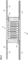
- a first embodiment of a capacitor device 10 according to the invention is shown. It is provided with a housing 20, which preferably acts electrically insulating. Inside this housing 20, a capacitor unit 30 is arranged. It has a plurality of opposing capacitor plates 34, which are each to be referred to as capacitor plate package. They are all supported by a plate carrier 38. The respective plate carrier 38 simultaneously forms at least partially the connection interfaces 32a and 32b. At these connection interfaces 32a and 32b, contacting takes place in a mechanical and electrically conductive manner to later-connected line elements 110.
- the assembled variant is for example in Figure 3 to recognize.
- the joining in a mechanical manner preferably takes place by means of an interference fit, that is to say in particular by thermal shrinking.
- the line elements 110 are surrounded by an insulating layer 120, in particular made of plastic. This ensures a complete electrical insulation to the outside, which is then continued with the capacitor unit 10 through the housing 20.
- the gap between the capacitor device 10 and the line element 110 can be additionally electrically insulated, for example, with an insulating tape.
- the line elements 110 are hollow and the capacitor unit 30 is concentrated on the capacitor device 10.
- the line elements 110 can thus withstand bending and tensile loads, without causing such a voltage in the capacitor device 10 to fractures or mechanical damage to the capacitor unit 30.
- a further embodiment of a capacitor unit 30 according to the invention is shown.
- the individual capacitor plates 34 are coated with a dielectric layer, so that a stack for the capacitor unit 30 can be made available by subsequent pressing.
- the space required is reduced on the one hand and at the same time the necessary mechanical stability for the capacitor unit 30 is provided.
- Figure 4 shows a deployment situation in a schematic representation. So there is a conductor loop 100, as for example the Figure 3 can be taken, laid in a soil. The box shows an operating station, via which the voltage for the induction operation of the conductor loop 100 can be adjusted.
- a conductor loop is made flexible so that the conductor loop can be bent and inserted into any bore.
Landscapes
- Engineering & Computer Science (AREA)
- Power Engineering (AREA)
- Life Sciences & Earth Sciences (AREA)
- Mining & Mineral Resources (AREA)
- Geology (AREA)
- Microelectronics & Electronic Packaging (AREA)
- Manufacturing & Machinery (AREA)
- Environmental & Geological Engineering (AREA)
- Fluid Mechanics (AREA)
- Physics & Mathematics (AREA)
- General Life Sciences & Earth Sciences (AREA)
- Geochemistry & Mineralogy (AREA)
- Fixed Capacitors And Capacitor Manufacturing Machines (AREA)
Priority Applications (7)
| Application Number | Priority Date | Filing Date | Title |
|---|---|---|---|
| EP12154736.8A EP2623709A1 (fr) | 2011-10-27 | 2012-02-09 | Dispositif de condensateur pour une bande de roulement d'un dispositif destiné au transport in situ d'huile lourde et de bitume issus de gisements de sable oléagineux |
| CA2853565A CA2853565A1 (fr) | 2011-10-27 | 2012-10-17 | Dispositif a condensateur pour une boucle de conducteurs d'un dispositif pour le transport « in situ » d'huile lourde et de bitume depuis des gisements de sables bitumineux |
| PCT/EP2012/070560 WO2013060610A1 (fr) | 2011-10-27 | 2012-10-17 | Dispositif à condensateur pour une boucle de conducteurs d'un dispositif pour le transport « in situ » d'huile lourde et de bitume depuis des gisements de sables bitumineux |
| BR112014009933A BR112014009933A2 (pt) | 2011-10-27 | 2012-10-17 | dispositivo capacitor para um laço condutor em um dispositivo para a produção in-situ de óleo pesado e betume de depósitos de óleo - areia, laço condutor e método para a produção de um laço condutor |
| EP12775234.3A EP2756164A1 (fr) | 2011-10-27 | 2012-10-17 | Dispositif à condensateur pour une boucle de conducteurs d'un dispositif pour le transport « in situ » d'huile lourde et de bitume depuis des gisements de sables bitumineux |
| US14/354,037 US9558889B2 (en) | 2011-10-27 | 2012-10-17 | Capacitor device for a conductor loop in a device for the in-sity production of heavy oil and bitumen from oil-sand deposits |
| RU2014121195A RU2622556C2 (ru) | 2011-10-27 | 2012-10-17 | Конденсаторное устройство для проводящего шлейфа устройства для добычи "на месте" тяжелой нефти и битумов из месторождений нефтеносного песка |
Applications Claiming Priority (2)
| Application Number | Priority Date | Filing Date | Title |
|---|---|---|---|
| EP11186890 | 2011-10-27 | ||
| EP12154736.8A EP2623709A1 (fr) | 2011-10-27 | 2012-02-09 | Dispositif de condensateur pour une bande de roulement d'un dispositif destiné au transport in situ d'huile lourde et de bitume issus de gisements de sable oléagineux |
Publications (1)
| Publication Number | Publication Date |
|---|---|
| EP2623709A1 true EP2623709A1 (fr) | 2013-08-07 |
Family
ID=47046601
Family Applications (2)
| Application Number | Title | Priority Date | Filing Date |
|---|---|---|---|
| EP12154736.8A Withdrawn EP2623709A1 (fr) | 2011-10-27 | 2012-02-09 | Dispositif de condensateur pour une bande de roulement d'un dispositif destiné au transport in situ d'huile lourde et de bitume issus de gisements de sable oléagineux |
| EP12775234.3A Withdrawn EP2756164A1 (fr) | 2011-10-27 | 2012-10-17 | Dispositif à condensateur pour une boucle de conducteurs d'un dispositif pour le transport « in situ » d'huile lourde et de bitume depuis des gisements de sables bitumineux |
Family Applications After (1)
| Application Number | Title | Priority Date | Filing Date |
|---|---|---|---|
| EP12775234.3A Withdrawn EP2756164A1 (fr) | 2011-10-27 | 2012-10-17 | Dispositif à condensateur pour une boucle de conducteurs d'un dispositif pour le transport « in situ » d'huile lourde et de bitume depuis des gisements de sables bitumineux |
Country Status (6)
| Country | Link |
|---|---|
| US (1) | US9558889B2 (fr) |
| EP (2) | EP2623709A1 (fr) |
| BR (1) | BR112014009933A2 (fr) |
| CA (1) | CA2853565A1 (fr) |
| RU (1) | RU2622556C2 (fr) |
| WO (1) | WO2013060610A1 (fr) |
Cited By (2)
| Publication number | Priority date | Publication date | Assignee | Title |
|---|---|---|---|---|
| DE102014206747A1 (de) * | 2014-04-08 | 2015-10-08 | Siemens Aktiengesellschaft | Induktor |
| WO2016045682A1 (fr) * | 2014-09-23 | 2016-03-31 | Ecp Licens Aps | Procédé de récupération améliorée de pétrole par électricité |
Families Citing this family (12)
| Publication number | Priority date | Publication date | Assignee | Title |
|---|---|---|---|---|
| US9353612B2 (en) | 2013-07-18 | 2016-05-31 | Saudi Arabian Oil Company | Electromagnetic assisted ceramic materials for heavy oil recovery and in-situ steam generation |
| DE102013219368A1 (de) * | 2013-09-26 | 2015-03-26 | Siemens Aktiengesellschaft | Induktor zur induktiven Heizung |
| FR3015548B1 (fr) * | 2013-12-20 | 2016-01-08 | Ene29 S Ar L | Outil de stimulation de puits comportant des elements capacitifs electriquement en parallele |
| CA2940876C (fr) | 2014-02-28 | 2022-06-21 | Leoni Kabel Holding Gmbh | Brin de cable pour un cable, en particulier pour un cable a induction, cable et procede servant a fabriquer un brin de cable |
| EP2947261B1 (fr) * | 2014-05-21 | 2016-12-14 | Siemens Aktiengesellschaft | Inducteur et procédé de chauffage d'une formation géologique |
| EP2947262B1 (fr) * | 2014-05-21 | 2016-12-14 | Siemens Aktiengesellschaft | Inducteur et procédé de chauffage d'une formation géologique |
| CN106605037B (zh) * | 2014-08-11 | 2019-06-28 | 艾尼股份公司 | 用于碳氢化合物的回收的射频(rf)系统 |
| CN106797066B (zh) * | 2014-08-11 | 2020-03-27 | 艾尼股份公司 | 产生rf信号的传播的差分模式中的干扰的设备及其阵列 |
| DE102015208056A1 (de) * | 2015-04-30 | 2016-11-03 | Siemens Aktiengesellschaft | Heizvorrichtung zur induktiven Heizung einer Kohlenwasserstofflagerstätte |
| US10053959B2 (en) | 2015-05-05 | 2018-08-21 | Saudi Arabian Oil Company | System and method for condensate blockage removal with ceramic material and microwaves |
| DE102015215448A1 (de) * | 2015-08-13 | 2017-02-16 | Siemens Aktiengesellschaft | Kabel, Induktor und Verfahren zur Herstellung eines Induktors zur Heizung einer geologischen Formation |
| US10612991B1 (en) | 2017-08-25 | 2020-04-07 | Fluke Corporation | High dynamic range capacitive pressure sensor |
Citations (2)
| Publication number | Priority date | Publication date | Assignee | Title |
|---|---|---|---|---|
| US3505575A (en) * | 1967-05-18 | 1970-04-07 | Comp Generale Electricite | Multiple capacitor |
| WO2009027305A2 (fr) | 2007-08-27 | 2009-03-05 | Siemens Aktiengesellschaft | Dispositif d'extraction in situ de bitume et d'huile très lourde |
Family Cites Families (9)
| Publication number | Priority date | Publication date | Assignee | Title |
|---|---|---|---|---|
| US2443605A (en) * | 1941-06-26 | 1948-06-22 | Hartford Nat Bank & Trust Co | Insulated casing |
| US2454102A (en) * | 1948-01-02 | 1948-11-16 | Gen Electric | Electric capacitor |
| US3278815A (en) * | 1961-01-11 | 1966-10-11 | Mallory & Co Inc P R | Electrical capacitor with a boron nitride dielectric |
| DE19505081C2 (de) * | 1994-02-17 | 1999-11-25 | Murata Manufacturing Co | Hochspannungskondensator und Verfahren zu dessen Herstellung |
| RU36857U1 (ru) * | 2003-12-29 | 2004-03-27 | Касьяненко Андрей Владимирович | Устройство для интенсификации добычи углеводородов |
| JP4973735B2 (ja) * | 2007-10-12 | 2012-07-11 | パナソニック株式会社 | ケースモールド型コンデンサとその製造方法 |
| DE102008062326A1 (de) | 2008-03-06 | 2009-09-17 | Siemens Aktiengesellschaft | Anordnung zur induktiven Heizung von Ölsand- und Schwerstöllagerstätten mittels stromführender Leiter |
| US8607862B2 (en) * | 2008-05-05 | 2013-12-17 | Siemens Aktiengesellschaft | Method and device for in-situ conveying of bitumen or very heavy oil |
| DE102008044953A1 (de) | 2008-08-29 | 2010-03-04 | Siemens Aktiengesellschaft | Anlage zur In-Situ-Gewinnung einer kohlenstoffhaltigen Substanz |
-
2012
- 2012-02-09 EP EP12154736.8A patent/EP2623709A1/fr not_active Withdrawn
- 2012-10-17 WO PCT/EP2012/070560 patent/WO2013060610A1/fr active Application Filing
- 2012-10-17 BR BR112014009933A patent/BR112014009933A2/pt not_active IP Right Cessation
- 2012-10-17 US US14/354,037 patent/US9558889B2/en not_active Expired - Fee Related
- 2012-10-17 CA CA2853565A patent/CA2853565A1/fr not_active Abandoned
- 2012-10-17 RU RU2014121195A patent/RU2622556C2/ru not_active IP Right Cessation
- 2012-10-17 EP EP12775234.3A patent/EP2756164A1/fr not_active Withdrawn
Patent Citations (2)
| Publication number | Priority date | Publication date | Assignee | Title |
|---|---|---|---|---|
| US3505575A (en) * | 1967-05-18 | 1970-04-07 | Comp Generale Electricite | Multiple capacitor |
| WO2009027305A2 (fr) | 2007-08-27 | 2009-03-05 | Siemens Aktiengesellschaft | Dispositif d'extraction in situ de bitume et d'huile très lourde |
Cited By (3)
| Publication number | Priority date | Publication date | Assignee | Title |
|---|---|---|---|---|
| DE102014206747A1 (de) * | 2014-04-08 | 2015-10-08 | Siemens Aktiengesellschaft | Induktor |
| WO2016045682A1 (fr) * | 2014-09-23 | 2016-03-31 | Ecp Licens Aps | Procédé de récupération améliorée de pétrole par électricité |
| US10563492B2 (en) | 2014-09-23 | 2020-02-18 | Eor Technologies Aps | Method for electrically enhanced oil recovery |
Also Published As
| Publication number | Publication date |
|---|---|
| WO2013060610A1 (fr) | 2013-05-02 |
| EP2756164A1 (fr) | 2014-07-23 |
| BR112014009933A2 (pt) | 2017-04-25 |
| RU2014121195A (ru) | 2015-12-10 |
| US20140301017A1 (en) | 2014-10-09 |
| US9558889B2 (en) | 2017-01-31 |
| CA2853565A1 (fr) | 2013-05-02 |
| RU2622556C2 (ru) | 2017-06-16 |
Similar Documents
| Publication | Publication Date | Title |
|---|---|---|
| EP2623709A1 (fr) | Dispositif de condensateur pour une bande de roulement d'un dispositif destiné au transport in situ d'huile lourde et de bitume issus de gisements de sable oléagineux | |
| WO2009109489A1 (fr) | Agencement de chauffage inductif des gisements de sable pétrolifère et de pétrole ultra lourd à l'aide de conducteurs électriques | |
| DE102006008922B4 (de) | Elektrische Abschirmanordnung | |
| WO2007107492A1 (fr) | Element de liaison pour un ensemble de blindage électrique | |
| EP3117442B1 (fr) | Traversée à haute tension | |
| DE102012010226A1 (de) | Verfahren zur Herstellung einer elektrotechnischen Spule sowie elektrotechnische Spule undElektromaschine mit einer solchen | |
| DE102019109516A1 (de) | Wicklung und Verfahren zur Herstellung einer Wicklung | |
| EP2900909A2 (fr) | Inducteur pour le chauffage de gisements d'huile lourde et de sable bitumineux | |
| EP2287864B1 (fr) | Traversée tubulaire | |
| WO2014044428A1 (fr) | Procédé de fabrication d'un condensateur et condensateur | |
| DE4008417A1 (de) | Vorrichtung zur verbindung der elektrischen anschluesse von kondensatoren | |
| WO2016096245A1 (fr) | Étanchéité aux milieux d'une zone de passage entre une zone humide et une zone sèche | |
| DE102012210802A1 (de) | Spulenanordnung und Verfahren zur Herstellung sowie Verwendung der Spulenanordnung mit Kühlung | |
| DE112017002164B4 (de) | Leitungsweg mit Rauschfilter | |
| EP3093938A1 (fr) | Système d'exécution haute tension | |
| WO2010072518A1 (fr) | Procédé et cylindre de support pour la fabrication d'un bobinage électrique | |
| WO2020008058A1 (fr) | Manchon de raccordement | |
| EP2947262B1 (fr) | Inducteur et procédé de chauffage d'une formation géologique | |
| EP2947261B1 (fr) | Inducteur et procédé de chauffage d'une formation géologique | |
| DE3223902C2 (de) | Verfahren zur Herstellung einer Verbindungsmuffe für Starkstromkabel und danach hergestellte Verbindungsmuffe | |
| WO2023098973A1 (fr) | Raccord de câble | |
| DE3050660C2 (de) | Einheit zur Verbindung eines Hochspannungswicklungsendes mit einem Kabel | |
| DE8225287U1 (de) | Rotationssymmetrischer Isolierköprer, insbesondere Endverschluß oder Durchführung | |
| DE102016110814B4 (de) | Elektrische Heizpatrone | |
| DE19723441A1 (de) | Koaxialer Schienenverteiler und Verfahren zu seiner Herstellung |
Legal Events
| Date | Code | Title | Description |
|---|---|---|---|
| PUAI | Public reference made under article 153(3) epc to a published international application that has entered the european phase |
Free format text: ORIGINAL CODE: 0009012 |
|
| AK | Designated contracting states |
Kind code of ref document: A1 Designated state(s): AL AT BE BG CH CY CZ DE DK EE ES FI FR GB GR HR HU IE IS IT LI LT LU LV MC MK MT NL NO PL PT RO RS SE SI SK SM TR |
|
| AX | Request for extension of the european patent |
Extension state: BA ME |
|
| STAA | Information on the status of an ep patent application or granted ep patent |
Free format text: STATUS: THE APPLICATION IS DEEMED TO BE WITHDRAWN |
|
| 18D | Application deemed to be withdrawn |
Effective date: 20140208 |