EP2622690B1 - Battery current sensor - Google Patents
Battery current sensor Download PDFInfo
- Publication number
- EP2622690B1 EP2622690B1 EP11773876.5A EP11773876A EP2622690B1 EP 2622690 B1 EP2622690 B1 EP 2622690B1 EP 11773876 A EP11773876 A EP 11773876A EP 2622690 B1 EP2622690 B1 EP 2622690B1
- Authority
- EP
- European Patent Office
- Prior art keywords
- battery
- current sensor
- clamping body
- magnetic
- sensor according
- Prior art date
- Legal status (The legal status is an assumption and is not a legal conclusion. Google has not performed a legal analysis and makes no representation as to the accuracy of the status listed.)
- Not-in-force
Links
- 239000002253 acid Substances 0.000 claims description 6
- 239000000696 magnetic material Substances 0.000 claims description 3
- 230000001681 protective effect Effects 0.000 claims description 2
- 239000004020 conductor Substances 0.000 description 4
- 230000005355 Hall effect Effects 0.000 description 3
- 238000012423 maintenance Methods 0.000 description 3
- 230000005284 excitation Effects 0.000 description 2
- 230000035939 shock Effects 0.000 description 2
- 238000009529 body temperature measurement Methods 0.000 description 1
- 238000002485 combustion reaction Methods 0.000 description 1
- 230000000295 complement effect Effects 0.000 description 1
- 239000012141 concentrate Substances 0.000 description 1
- 230000004907 flux Effects 0.000 description 1
- 238000009413 insulation Methods 0.000 description 1
- 230000010354 integration Effects 0.000 description 1
- 238000004519 manufacturing process Methods 0.000 description 1
- 238000005259 measurement Methods 0.000 description 1
- VIKNJXKGJWUCNN-XGXHKTLJSA-N norethisterone Chemical compound O=C1CC[C@@H]2[C@H]3CC[C@](C)([C@](CC4)(O)C#C)[C@@H]4[C@@H]3CCC2=C1 VIKNJXKGJWUCNN-XGXHKTLJSA-N 0.000 description 1
- 239000011347 resin Substances 0.000 description 1
- 229920005989 resin Polymers 0.000 description 1
Images

Classifications
-
- G—PHYSICS
- G01—MEASURING; TESTING
- G01R—MEASURING ELECTRIC VARIABLES; MEASURING MAGNETIC VARIABLES
- G01R31/00—Arrangements for testing electric properties; Arrangements for locating electric faults; Arrangements for electrical testing characterised by what is being tested not provided for elsewhere
- G01R31/36—Arrangements for testing, measuring or monitoring the electrical condition of accumulators or electric batteries, e.g. capacity or state of charge [SoC]
-
- G—PHYSICS
- G01—MEASURING; TESTING
- G01R—MEASURING ELECTRIC VARIABLES; MEASURING MAGNETIC VARIABLES
- G01R31/00—Arrangements for testing electric properties; Arrangements for locating electric faults; Arrangements for electrical testing characterised by what is being tested not provided for elsewhere
- G01R31/36—Arrangements for testing, measuring or monitoring the electrical condition of accumulators or electric batteries, e.g. capacity or state of charge [SoC]
- G01R31/382—Arrangements for monitoring battery or accumulator variables, e.g. SoC
-
- G—PHYSICS
- G01—MEASURING; TESTING
- G01R—MEASURING ELECTRIC VARIABLES; MEASURING MAGNETIC VARIABLES
- G01R31/00—Arrangements for testing electric properties; Arrangements for locating electric faults; Arrangements for electrical testing characterised by what is being tested not provided for elsewhere
- G01R31/36—Arrangements for testing, measuring or monitoring the electrical condition of accumulators or electric batteries, e.g. capacity or state of charge [SoC]
- G01R31/364—Battery terminal connectors with integrated measuring arrangements
-
- H—ELECTRICITY
- H01—ELECTRIC ELEMENTS
- H01R—ELECTRICALLY-CONDUCTIVE CONNECTIONS; STRUCTURAL ASSOCIATIONS OF A PLURALITY OF MUTUALLY-INSULATED ELECTRICAL CONNECTING ELEMENTS; COUPLING DEVICES; CURRENT COLLECTORS
- H01R11/00—Individual connecting elements providing two or more spaced connecting locations for conductive members which are, or may be, thereby interconnected, e.g. end pieces for wires or cables supported by the wire or cable and having means for facilitating electrical connection to some other wire, terminal, or conductive member, blocks of binding posts
- H01R11/11—End pieces or tapping pieces for wires, supported by the wire and for facilitating electrical connection to some other wire, terminal or conductive member
- H01R11/28—End pieces consisting of a ferrule or sleeve
- H01R11/281—End pieces consisting of a ferrule or sleeve for connections to batteries
-
- H—ELECTRICITY
- H01—ELECTRIC ELEMENTS
- H01R—ELECTRICALLY-CONDUCTIVE CONNECTIONS; STRUCTURAL ASSOCIATIONS OF A PLURALITY OF MUTUALLY-INSULATED ELECTRICAL CONNECTING ELEMENTS; COUPLING DEVICES; CURRENT COLLECTORS
- H01R13/00—Details of coupling devices of the kinds covered by groups H01R12/70 or H01R24/00 - H01R33/00
- H01R13/66—Structural association with built-in electrical component
- H01R13/665—Structural association with built-in electrical component with built-in electronic circuit
- H01R13/6683—Structural association with built-in electrical component with built-in electronic circuit with built-in sensor
-
- G—PHYSICS
- G01—MEASURING; TESTING
- G01R—MEASURING ELECTRIC VARIABLES; MEASURING MAGNETIC VARIABLES
- G01R15/00—Details of measuring arrangements of the types provided for in groups G01R17/00 - G01R29/00, G01R33/00 - G01R33/26 or G01R35/00
- G01R15/14—Adaptations providing voltage or current isolation, e.g. for high-voltage or high-current networks
- G01R15/18—Adaptations providing voltage or current isolation, e.g. for high-voltage or high-current networks using inductive devices, e.g. transformers
- G01R15/183—Adaptations providing voltage or current isolation, e.g. for high-voltage or high-current networks using inductive devices, e.g. transformers using transformers with a magnetic core
-
- G—PHYSICS
- G01—MEASURING; TESTING
- G01R—MEASURING ELECTRIC VARIABLES; MEASURING MAGNETIC VARIABLES
- G01R15/00—Details of measuring arrangements of the types provided for in groups G01R17/00 - G01R29/00, G01R33/00 - G01R33/26 or G01R35/00
- G01R15/14—Adaptations providing voltage or current isolation, e.g. for high-voltage or high-current networks
- G01R15/20—Adaptations providing voltage or current isolation, e.g. for high-voltage or high-current networks using galvano-magnetic devices, e.g. Hall-effect devices, i.e. measuring a magnetic field via the interaction between a current and a magnetic field, e.g. magneto resistive or Hall effect devices
-
- H—ELECTRICITY
- H01—ELECTRIC ELEMENTS
- H01R—ELECTRICALLY-CONDUCTIVE CONNECTIONS; STRUCTURAL ASSOCIATIONS OF A PLURALITY OF MUTUALLY-INSULATED ELECTRICAL CONNECTING ELEMENTS; COUPLING DEVICES; CURRENT COLLECTORS
- H01R2201/00—Connectors or connections adapted for particular applications
- H01R2201/26—Connectors or connections adapted for particular applications for vehicles
Definitions
- the present invention relates to a current sensor for a battery, in particular for a battery of the lead-acid type with posts for connection to positive and negative leads respectively.
- Batteries of the lead-acid type are currently used in automobiles and in stand-by power applications as well as other applications.
- Such batteries have standardized connection posts for both the positive and negative connections, the posts having a truncated cone-shape with a small cone angle, the complementary connecting part typically comprising a tubular connection clamp with flanges that are squeezed together by means of a bolt to tighten the tubular body on the connection posts.
- a conducting cable for the power connection is usually welded, soldered, clamped, or crimped to the tubular connection clamp.
- Lead-acid batteries may supply currents over a very large operating range, from milliamperes up to peaks of a few hundred, even a thousand or more amperes, for example when starting a combustion engine.
- the current sensor for such batteries thus needs to be robust and have dimensions sufficiently large to be able to support the very high peak currents without damage.
- a battery current sensor comprising a battery post connection clamp portion comprising a tubular split clamping body configured to be clamped around a terminal post of a battery, and a current sensing portion comprising a magnetic circuit and a magnetic field sensor
- the magnetic circuit comprises a magnetic core surrounding the tubular clamping body.
- the battery post connection clamp portion comprises flanges extending from free ends of the tubular clamping body, configured to be biased together for tightening the tubular clamping body on a battery terminal post, the flanges having a height H 2 that is less than a height H1 of the tubular clamping body.
- the magnetic circuit comprises a magnetic core surrounding a portion of the tubular clamping body adjacent the flanges.
- a particularly compact and low profile sensor integrated in a connection clamp is provided, yet in view of the large diameter magnetic circuit surrounding the connection post is able to reliably measure large electrical currents.
- Integration of the magnetic circuit and magnetic field sensor around the battery connection post provides a particularly compact arrangement and reduces exposure of the sensor to external objects during assembly, use or maintenance, the sensor being partially protected by the connection clamp itself.
- the sensor accurately measures the entire current flowing in and out of the battery including any leakages or secondary conductors that may be connected or tapped off the connection clamp or conducting lead.
- a short circuit or secondary conductor connected to the battery terminal post may not be detected since the sensor is arranged on or around the main conducting lead.
- sensing function is configured in parallel to the primary conductor and does not insert between the connection between the battery lead and the battery terminal. An interruption of the primary conductor line introduces further risks of failure and renders the cable to battery connection more complex.
- a temperature sensor may also be directly integrated in the current sensor. Since it is mounted on the connection clamp that fits on the battery post terminal, an accurate temperature measurement of the battery in a compact and cost effective configuration is provided.
- the flanges may advantageously be positioned at a top end of the tubular clamping body and the magnetic circuit positioned below the flanges towards a bottom end of the clamping body.
- the magnetic circuit may advantageously be positioned in the current sensor such that when the current sensor is mounted on a battery post the magnetic circuit is proximate and adjacent an upper outer surface of the battery.
- the sensor comprises an insulating and protective housing surrounding the magnetic circuit, magnetic field sensor and at least a portion of the tubular clamping portion.
- the sensor may further comprise a connector having a housing portion integrally formed with the current sensor housing and configured for connection to a connector of external circuitry.
- the magnetic circuit comprises a magnetic core having an air gap, the magnetic field sensor being positioned in the air gap.
- the magnetic circuit and magnetic field detector may be configured to operate as an open-loop current sensor.
- the magnetic field sensor may include a circuit board on which a magnetic field detector such as a Hall effect detector, is mounted.
- a battery current sensor 1 comprises a battery post connection clamp portion 2 and a current sensing portion 4.
- the battery post connection clamp portion is mountable around a battery post 3 of a battery 5 that may typically be of the lead-acid type that is widely used in automotive, stand-by and other applications.
- the battery post may have standardized dimensions with a slightly conical clamping surface as per se well-known.
- the invention however may also be for batteries of other types or for battery terminal posts that are cylindrical or slightly conical of non-standardized dimensions.
- the battery post connection clamp portion 2 comprises a split tubular clamping body 6 with flanges 8 extending outwardly and generally radially from free ends of the clamping body, the flanges having passages to receive a clamping bolt 10 therethrough, the clamping bolt may press the flanges together thus clamping the tubular body around the battery terminal post 3.
- the tubular body has an axial height H1 that is greater than the axial height H2 of the flanges.
- the flanges extend, in a preferred embodiment, from an upper surface 9 of the tubular body as seen in relation to the mounting position of the clamping body on a battery post.
- the battery post connection clamp portion further comprises a primary cable connection portion 12 for connection to a main conducting lead 7 and optionally connection portions for connecting other leads to the battery post.
- the connection portions for the primary cables and secondary cables may have various shapes and configurations as known in the art.
- the current sensing portion 4 comprises a magnetic circuit 16 with an annular shaped magnetic core that surrounds the battery post, and a magnetic field sensor 18.
- the magnetic field sensor detects the magnetic field generated by the electrical current flowing through the battery post, whereby the magnetic core of the magnetic circuit concentrates the magnetic flux.
- the magnetic core is provided with an air gap and the magnetic field detector is inserted in the air gap in order to pick up the concentrated magnetic field in the air gap.
- the magnetic field sensor may comprise a Hall effect sensor that is for example integrated in an ASIC that is mounted on a circuit board, for example a printed circuit board 26. Other magnetic field sensors may however also be used.
- the printed circuit board may also be provided with other electrical and electronic circuitry for signal processing and supply.
- the current sensor may function in an open-loop manner (known as an open-loop current sensor) which means that there is no feed-back signal that is used to cancel the magnetic field in the magnetic circuit.
- the magnetic core may be made of soft magnetic material in the form of a non-laminated core or in the form of stacked laminated sheets to reduce eddy currents as is known in the art.
- magnetic field detectors and magnetic circuit configurations may be used.
- other magnetic field detectors such as fluxgate or magneto-resistive detectors may however be used instead of Hall effect detectors.
- the magnetic core may be closed i.e. without air gap, and the current sensor may function in a closed-loop manner and comprise a secondary coil wound around the magnetic circuit that is driven with a current that seeks to cancel the magnetic field generated by the current flowing through the battery post.
- the magnetic field detector of figure 3 is of the fluxgate type comprising a magnetic circuit with an annular shaped saturable magnetic core 16' that surrounds the battery post.
- the saturable magnetic core 16' may be made of an amorphous magnetic material ribbon or strip wound around an insulating support 29.
- a coil 28 is wound around the magnetic core and insulating support, and is configured to be connected to a signal processing circuit (via the connector portion 22 as illustrated in fig 1 ) that generates an alternating excitation current and reads the resulting signal bias that is an image of the primary current flowing through the battery terminal.
- the functioning principle of the fluxgate sensor of this type is per se known. Other fluxgate configurations could also be used in the present invention, for example with separate excitation and compensation coils.
- An advantageous embodiment is the open-loop configuration as illustrated in Figures 2a, 2b in view of the low cost and simple and reliable operation as well as the ability to measure high currents.
- the current sensing portion 4 further comprises a housing 20 that provides insulation and protection to the magnetic circuit and magnetic field sensor, and a connector 2 with a housing portion integrally formed in the housing 20 for connection of the current sensor to external circuitry.
- the housing 20 is formed around and fixed to the battery post connection clamp portion 2.
- the magnetic circuit 16 is advantageously positioned below the flanges 8 and surrounding the lower portion of the tubular body 6 thus forming a particularly compact and well-protected current sensing portion. Protection of the current sensing portion is also enhanced as it is arranged under the flanges 8 and clamping bolt 10 for positioning against or right next to a surface 13 of the battery 5 under the clamping bolt.
- the battery current sensor preferably has an overall height that is equal or less that the height H4 of the battery terminal well 15 so that the sensor does not protrude above the uppermost surface of the battery.
- the magnetic circuit surrounds the battery post all electrical current flowing in or out the battery is measured irrespective of whether they are currently leaks or short circuits or secondary lines connected to the battery post where the current does not flow through the primary cable.
- the current sensing portion may further comprise a temperature sensor housed in the housing 20 and connected either to the circuit board 26 of the magnetic field sensor or to separate circuitry and connectable with the current sensor to external circuitry via the connector 22 pluggable to an external connector 11.
- a temperature sensor within the current sensing portion provides a particularly compact and well-protected arrangement that nevertheless allows accurate measurement of the battery temperature through the very close connection to the battery post.
- the temperature sensor may for example include a thermocouple (not shown) that is mounted against or fixed on the outer surface of the tubular body 6 of the connection clamping portion 2.
- An insulating resin may be injected inside the housing 20 to fill up the free space in the housing and secure the magnetic circuit and magnetic field detector and other components within the housing.
- the magnetic circuit As the magnetic core of the magnetic circuit surrounds the tubular clamping body that is clamped around the battery post the magnetic circuit has a relatively large diameter, much larger than would normally be provided around a cable or lead connected to the clamp, this enables the current sensing portion to measure large amplitude currents in a particularly compact configuration that is also well protected.
Landscapes
- Physics & Mathematics (AREA)
- General Physics & Mathematics (AREA)
- Engineering & Computer Science (AREA)
- Microelectronics & Electronic Packaging (AREA)
- Measuring Instrument Details And Bridges, And Automatic Balancing Devices (AREA)
- Connection Of Batteries Or Terminals (AREA)
- Secondary Cells (AREA)
Description
- The present invention relates to a current sensor for a battery, in particular for a battery of the lead-acid type with posts for connection to positive and negative leads respectively.
- Batteries of the lead-acid type are currently used in automobiles and in stand-by power applications as well as other applications. Such batteries have standardized connection posts for both the positive and negative connections, the posts having a truncated cone-shape with a small cone angle, the complementary connecting part typically comprising a tubular connection clamp with flanges that are squeezed together by means of a bolt to tighten the tubular body on the connection posts. A conducting cable for the power connection is usually welded, soldered, clamped, or crimped to the tubular connection clamp.
- It is known to provide a current sensor around the conducting cable or in the region of the connection between the cable and the connecting clamp in order to measure the electrical current flowing in or out of the battery. Lead-acid batteries may supply currents over a very large operating range, from milliamperes up to peaks of a few hundred, even a thousand or more amperes, for example when starting a combustion engine. The current sensor for such batteries thus needs to be robust and have dimensions sufficiently large to be able to support the very high peak currents without damage. In addition, it would be desirable to be able to measure such large currents.
- Existing current sensors for battery post connection leads are bulky and costly and in view of their mounting around the connecting lead easily subject to damage, for example during mounting or maintenance. Such sensors are also subject to harsh operating conditions such as vibration, shock and a large range of operating temperatures from minus 40° to 125° that may be found in the engine compartment of an automobile. It is known to provide battery post connectors with integrated current sensors as described in
EP0214532 ,WO2009/153036A1 , andUS2003/0017753 .
It is an object of this invention to provide a current sensor for a battery with terminal connection posts, for example batteries of the lead-acid type used in automobiles or in stand-by applications, that is robust, reliable, compact and that can support harsh operating conditions such as a large temperature range, high temperatures, and/or vibration and shocks. - It is advantageous to provide a current sensor that is able to measure currents over a large range, from milli amperes to a few hundred or even a thousand or more amperes and yet that is compact and economical to manufacture.
- It is advantageous to provide a current sensor for connection to a battery post that has a low exposure to damage during mounting, use or maintenance.
- Objects of this invention have been achieved by providing the battery post current sensor according to
claim 1. - Disclosed herein is a battery current sensor comprising a battery post connection clamp portion comprising a tubular split clamping body configured to be clamped around a terminal post of a battery, and a current sensing portion comprising a magnetic circuit and a magnetic field sensor The magnetic circuit comprises a magnetic core surrounding the tubular clamping body. The battery post connection clamp portion comprises flanges extending from free ends of the tubular clamping body, configured to be biased together for tightening the tubular clamping body on a battery terminal post, the flanges having a height H2 that is less than a height H1 of the tubular clamping body. The magnetic circuit comprises a magnetic core surrounding a portion of the tubular clamping body adjacent the flanges.
- Advantageously, a particularly compact and low profile sensor integrated in a connection clamp is provided, yet in view of the large diameter magnetic circuit surrounding the connection post is able to reliably measure large electrical currents. Integration of the magnetic circuit and magnetic field sensor around the battery connection post provides a particularly compact arrangement and reduces exposure of the sensor to external objects during assembly, use or maintenance, the sensor being partially protected by the connection clamp itself. Moreover, as the magnetic circuit surrounds the battery post, the sensor accurately measures the entire current flowing in and out of the battery including any leakages or secondary conductors that may be connected or tapped off the connection clamp or conducting lead. In conventional sensors, a short circuit or secondary conductor connected to the battery terminal post may not be detected since the sensor is arranged on or around the main conducting lead.
- Another advantage of the invention is that the sensing function is configured in parallel to the primary conductor and does not insert between the connection between the battery lead and the battery terminal. An interruption of the primary conductor line introduces further risks of failure and renders the cable to battery connection more complex.
- A temperature sensor may also be directly integrated in the current sensor. Since it is mounted on the connection clamp that fits on the battery post terminal, an accurate temperature measurement of the battery in a compact and cost effective configuration is provided.
- The flanges may advantageously be positioned at a top end of the tubular clamping body and the magnetic circuit positioned below the flanges towards a bottom end of the clamping body.
- The magnetic circuit may advantageously be positioned in the current sensor such that when the current sensor is mounted on a battery post the magnetic circuit is proximate and adjacent an upper outer surface of the battery.
- The sensor comprises an insulating and protective housing surrounding the magnetic circuit, magnetic field sensor and at least a portion of the tubular clamping portion. The sensor may further comprise a connector having a housing portion integrally formed with the current sensor housing and configured for connection to a connector of external circuitry.
- In an embodiment, the magnetic circuit comprises a magnetic core having an air gap, the magnetic field sensor being positioned in the air gap. The magnetic circuit and magnetic field detector may be configured to operate as an open-loop current sensor. The magnetic field sensor may include a circuit board on which a magnetic field detector such as a Hall effect detector, is mounted.
- Further objects and advantageous aspects of the invention will be apparent from the claims, the following detailed description and of an embodiment of the invention and the annexed drawings in which:
-
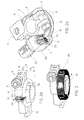
Figure 1 is a view of a battery current sensor according to the invention mounted on a battery terminal post; -
Figure 2a is a perspective view of a battery current sensor, with a portion of the housing cut away for better visibility, according to an embodiment of the invention ; -
Figure 2b is another perspective view of the sensor offigure 2a with further housing parts and components removed in order to see the magnetic circuit and the magnetic field sensor; and -
Figure 3 is a perspective view of a battery current sensor, with the housing removed in order to see the magnetic field sensor according to another embodiment of the invention. - Referring to the figures, a
battery current sensor 1 according to an embodiment of this invention comprises a battery postconnection clamp portion 2 and acurrent sensing portion 4. The battery post connection clamp portion is mountable around abattery post 3 of a battery 5 that may typically be of the lead-acid type that is widely used in automotive, stand-by and other applications. The battery post may have standardized dimensions with a slightly conical clamping surface as per se well-known. The invention however may also be for batteries of other types or for battery terminal posts that are cylindrical or slightly conical of non-standardized dimensions. - The battery post
connection clamp portion 2 comprises a splittubular clamping body 6 withflanges 8 extending outwardly and generally radially from free ends of the clamping body, the flanges having passages to receive aclamping bolt 10 therethrough, the clamping bolt may press the flanges together thus clamping the tubular body around thebattery terminal post 3. The tubular body has an axial height H1 that is greater than the axial height H2 of the flanges. The flanges extend, in a preferred embodiment, from anupper surface 9 of the tubular body as seen in relation to the mounting position of the clamping body on a battery post. A certain space H3 below the flange is thus provided to allow a magnetic circuit of the current sensing portion to be positioned around the tubular clamping body as will be described in more detail further on. The battery post connection clamp portion further comprises a primarycable connection portion 12 for connection to a main conducting lead 7 and optionally connection portions for connecting other leads to the battery post. The connection portions for the primary cables and secondary cables may have various shapes and configurations as known in the art. - The
current sensing portion 4 comprises amagnetic circuit 16 with an annular shaped magnetic core that surrounds the battery post, and amagnetic field sensor 18. The magnetic field sensor detects the magnetic field generated by the electrical current flowing through the battery post, whereby the magnetic core of the magnetic circuit concentrates the magnetic flux. In the embodiment shown, the magnetic core is provided with an air gap and the magnetic field detector is inserted in the air gap in order to pick up the concentrated magnetic field in the air gap. The magnetic field sensor may comprise a Hall effect sensor that is for example integrated in an ASIC that is mounted on a circuit board, for example a printedcircuit board 26. Other magnetic field sensors may however also be used. The printed circuit board may also be provided with other electrical and electronic circuitry for signal processing and supply. In the configuration shown and discussed above the current sensor may function in an open-loop manner (known as an open-loop current sensor) which means that there is no feed-back signal that is used to cancel the magnetic field in the magnetic circuit. - The magnetic core may be made of soft magnetic material in the form of a non-laminated core or in the form of stacked laminated sheets to reduce eddy currents as is known in the art.
- Within the scope of the invention other magnetic field detectors and magnetic circuit configurations may be used. For example, other magnetic field detectors such as fluxgate or magneto-resistive detectors may however be used instead of Hall effect detectors. Also, the magnetic core may be closed i.e. without air gap, and the current sensor may function in a closed-loop manner and comprise a secondary coil wound around the magnetic circuit that is driven with a current that seeks to cancel the magnetic field generated by the current flowing through the battery post.
- Referring to
figure 3 (in conjunction withfigure 1 ), an example of another embodiment of a magnetic field detector is shown. The magnetic field detector offigure 3 is of the fluxgate type comprising a magnetic circuit with an annular shaped saturable magnetic core 16' that surrounds the battery post. The saturable magnetic core 16' may be made of an amorphous magnetic material ribbon or strip wound around aninsulating support 29. Acoil 28 is wound around the magnetic core and insulating support, and is configured to be connected to a signal processing circuit (via theconnector portion 22 as illustrated infig 1 ) that generates an alternating excitation current and reads the resulting signal bias that is an image of the primary current flowing through the battery terminal. The functioning principle of the fluxgate sensor of this type is per se known. Other fluxgate configurations could also be used in the present invention, for example with separate excitation and compensation coils. - An advantageous embodiment is the open-loop configuration as illustrated in
Figures 2a, 2b in view of the low cost and simple and reliable operation as well as the ability to measure high currents. - The
current sensing portion 4 further comprises ahousing 20 that provides insulation and protection to the magnetic circuit and magnetic field sensor, and aconnector 2 with a housing portion integrally formed in thehousing 20 for connection of the current sensor to external circuitry. Thehousing 20 is formed around and fixed to the battery postconnection clamp portion 2. Themagnetic circuit 16 is advantageously positioned below theflanges 8 and surrounding the lower portion of thetubular body 6 thus forming a particularly compact and well-protected current sensing portion. Protection of the current sensing portion is also enhanced as it is arranged under theflanges 8 and clampingbolt 10 for positioning against or right next to asurface 13 of the battery 5 under the clamping bolt. The battery current sensor preferably has an overall height that is equal or less that the height H4 of the battery terminal well 15 so that the sensor does not protrude above the uppermost surface of the battery. - Also, as the magnetic circuit surrounds the battery post all electrical current flowing in or out the battery is measured irrespective of whether they are currently leaks or short circuits or secondary lines connected to the battery post where the current does not flow through the primary cable.
- The current sensing portion may further comprise a temperature sensor housed in the
housing 20 and connected either to thecircuit board 26 of the magnetic field sensor or to separate circuitry and connectable with the current sensor to external circuitry via theconnector 22 pluggable to anexternal connector 11. Inclusion of a temperature sensor within the current sensing portion provides a particularly compact and well-protected arrangement that nevertheless allows accurate measurement of the battery temperature through the very close connection to the battery post. The temperature sensor may for example include a thermocouple (not shown) that is mounted against or fixed on the outer surface of thetubular body 6 of theconnection clamping portion 2. - An insulating resin may be injected inside the
housing 20 to fill up the free space in the housing and secure the magnetic circuit and magnetic field detector and other components within the housing. - As the magnetic core of the magnetic circuit surrounds the tubular clamping body that is clamped around the battery post the magnetic circuit has a relatively large diameter, much larger than would normally be provided around a cable or lead connected to the clamp, this enables the current sensing portion to measure large amplitude currents in a particularly compact configuration that is also well protected.
Claims (12)
- Battery current sensor comprising a battery post connection clamp portion (2) comprising a split tubular clamping body configured to be clamped around a terminal post (3) of a battery (5), flanges (8) extending from free ends of the split tubular clamping body, configured to be biased together for tightening the tubular clamping body on a battery terminal post, a current sensing portion comprising a magnetic circuit, and an insulating and protective housing surrounding the magnetic circuit and at least a portion of the tubular clamping portion, wherein the flanges have a height (H2) that is less than a height (H1) of the tubular clamping body and wherein the magnetic circuit comprises a magnetic core (16, 16') surrounding a portion of the tubular clamping body (6) adjacent the flanges.
- Battery current sensor according to the preceding claim, wherein the flanges are positioned at a top end of the tubular clamping body and the magnetic circuit is positioned below the flanges towards a bottom end of the clamping body, said top end of the tubular clamping body having an inner diameter smaller than an inner diameter of said bottom end of the tubular clamping body.
- Battery current sensor according to anyone of the preceding claims, wherein the magnetic circuit is positioned in the current sensor configured such that when the current sensor is mounted on a battery post the magnetic circuit is proximate and adjacent an upper outer surface (13) of the battery.
- Battery current sensor according to any one of the preceding claims, further comprising a connector having a housing portion integrally formed with the current sensor housing and configured for connection to a connector of external circuitry.
- Battery current sensor according to claim 3 or 4 further comprising a temperature sensor mounted in the housing.
- Battery current sensor according to anyone of the preceding claims, wherein the current sensor has an overall height and size configured to fit within a terminal post well (15) of an automotive battery of the lead-acid type.
- Battery current sensor according to anyone of the preceding claims, wherein the magnetic circuit comprises a magnetic core having an air gap, and a magnetic field sensor positioned in the air gap.
- Battery current sensor according to claim 7, wherein the magnetic circuit and magnetic field sensor are configured to operate as an open-loop current sensor.
- Battery current sensor according to claim 7 or 8, wherein the magnetic field sensor comprises a circuit board on which a magnetic field detector is mounted.
- Battery current sensor according to anyone of the preceding claims 1-6 wherein the current sensing portion is configure to function in a closed-loop manner and comprises a secondary coil wound around the magnetic circuit that is driven with a current that seeks to cancel the magnetic field generated by the current flowing through the battery post.
- Battery current sensor according to anyone of the preceding claims 1-6 or 10 wherein the magnetic core completely surrounds, without air gap, the tubular clamping body.
- Battery current sensor according to claim 11 wherein the current sensing portion is configured as a fluxgate sensor and comprises a coil (29) wound around the magnetic core (16'), the magnetic core being made of a soft saturable magnetic material.
Priority Applications (1)
| Application Number | Priority Date | Filing Date | Title |
|---|---|---|---|
| EP11773876.5A EP2622690B1 (en) | 2010-09-28 | 2011-09-23 | Battery current sensor |
Applications Claiming Priority (3)
| Application Number | Priority Date | Filing Date | Title |
|---|---|---|---|
| EP10180620A EP2434583A1 (en) | 2010-09-28 | 2010-09-28 | Battery current sensor |
| EP11773876.5A EP2622690B1 (en) | 2010-09-28 | 2011-09-23 | Battery current sensor |
| PCT/IB2011/054209 WO2012042457A1 (en) | 2010-09-28 | 2011-09-23 | Battery current sensor |
Publications (2)
| Publication Number | Publication Date |
|---|---|
| EP2622690A1 EP2622690A1 (en) | 2013-08-07 |
| EP2622690B1 true EP2622690B1 (en) | 2014-08-13 |
Family
ID=43617955
Family Applications (2)
| Application Number | Title | Priority Date | Filing Date |
|---|---|---|---|
| EP10180620A Withdrawn EP2434583A1 (en) | 2010-09-28 | 2010-09-28 | Battery current sensor |
| EP11773876.5A Not-in-force EP2622690B1 (en) | 2010-09-28 | 2011-09-23 | Battery current sensor |
Family Applications Before (1)
| Application Number | Title | Priority Date | Filing Date |
|---|---|---|---|
| EP10180620A Withdrawn EP2434583A1 (en) | 2010-09-28 | 2010-09-28 | Battery current sensor |
Country Status (6)
| Country | Link |
|---|---|
| US (1) | US9535130B2 (en) |
| EP (2) | EP2434583A1 (en) |
| JP (1) | JP2013539038A (en) |
| KR (1) | KR101795834B1 (en) |
| CN (1) | CN103140990B (en) |
| WO (1) | WO2012042457A1 (en) |
Cited By (1)
| Publication number | Priority date | Publication date | Assignee | Title |
|---|---|---|---|---|
| WO2018011481A1 (en) | 2016-07-11 | 2018-01-18 | Renault Sas | Device for measuring a current, the device being fastened vertically onto a battery terminal |
Families Citing this family (21)
| Publication number | Priority date | Publication date | Assignee | Title |
|---|---|---|---|---|
| PL2658044T3 (en) | 2012-04-24 | 2021-04-19 | Arteche Lantegi Elkartea, S.A. | High-voltage connector |
| DE202013001992U1 (en) * | 2012-07-05 | 2013-10-09 | Ellenberger & Poensgen Gmbh | Sensor module for arc detection in vehicles |
| DE202013100811U1 (en) | 2013-02-25 | 2014-06-02 | Rp-Technik E.K. | Power supply device with battery monitoring |
| DE102014102366B4 (en) | 2013-02-25 | 2021-03-04 | Rp-Technik Gmbh | Energy supply device with battery monitoring and battery monitoring process |
| DE102013104756B4 (en) * | 2013-05-08 | 2025-07-31 | HELLA GmbH & Co. KGaA | Arrangement of a sensor electronics on a pole terminal of a battery and method for producing such an arrangement |
| US9583798B2 (en) * | 2013-10-17 | 2017-02-28 | Ford Global Technologies, Llc | Electric vehicle battery thermocouple |
| EP2911269B1 (en) | 2014-02-24 | 2017-07-05 | RP-Technik GmbH | Power supply device with battery monitoring and battery monitoring method |
| USD777669S1 (en) | 2014-04-19 | 2017-01-31 | Mark Taylor | Battery monitoring clip |
| USD777055S1 (en) | 2014-04-19 | 2017-01-24 | Mark Taylor | Battery monitoring clamp |
| US9472870B2 (en) | 2014-05-06 | 2016-10-18 | Continental Automotive Systems, Inc. | Battery sensor clamp assembly |
| EP3093672B1 (en) * | 2015-05-09 | 2020-08-12 | LEM International SA | Current transducer with integrated primary conductor bar |
| JP6159893B1 (en) | 2015-11-17 | 2017-07-05 | テレフオンアクチーボラゲット エルエム エリクソン(パブル) | Generating a key for use as a shared secret key |
| JP6982728B2 (en) * | 2016-02-01 | 2021-12-17 | パナソニックIpマネジメント株式会社 | Battery sensor device |
| US9859624B2 (en) * | 2016-04-29 | 2018-01-02 | Deere & Company | Electrical connector assembly |
| US10165670B2 (en) | 2016-04-29 | 2018-12-25 | Deere & Company | Electrical connector assembly |
| US10932360B2 (en) | 2018-07-19 | 2021-02-23 | Ut-Battelle, Llc | Flexible sensor technology |
| GB201912736D0 (en) | 2019-09-04 | 2019-10-16 | Cdo2 Ltd | Battery sesnor arrangement and method of balancing batteries |
| EP3796007B1 (en) * | 2019-09-21 | 2022-03-02 | LEM International SA | Current transducer |
| US20210408614A1 (en) * | 2020-06-26 | 2021-12-30 | K&N Engineering, Inc. | Portable vehicle battery pack |
| TWI814300B (en) * | 2021-09-03 | 2023-09-01 | 凡甲科技股份有限公司 | Electrical connector and electrical connector assembly |
| CN118068065A (en) * | 2022-11-22 | 2024-05-24 | 苏州力特奥维斯保险丝有限公司 | Dual channel current sensor |
Family Cites Families (26)
| Publication number | Priority date | Publication date | Assignee | Title |
|---|---|---|---|---|
| CA1174278A (en) * | 1982-09-16 | 1984-09-11 | Aurele Blain | Clamp-on ammeter |
| JPS6136960U (en) * | 1984-08-08 | 1986-03-07 | 本田技研工業株式会社 | Battery output terminal mounting structure |
| DE3532044A1 (en) * | 1985-09-09 | 1987-03-19 | Vdo Schindling | POLE CLAMP |
| ES2267244T3 (en) * | 1998-04-17 | 2007-03-01 | Ak Systemtechnik Ag | BATTERY MEASUREMENT TERMINAL. |
| DE19961311A1 (en) * | 1999-12-18 | 2001-07-26 | Bayerische Motoren Werke Ag | Battery sensor device, has attachment device, sensor combined into integrated unit; attachment device is connected to single pole and has conventional terminal |
| US6347958B1 (en) * | 2000-09-18 | 2002-02-19 | Real Power Cap Company | Connecting device to vehicle battery terminals |
| JP3697154B2 (en) * | 2000-11-01 | 2005-09-21 | 住友電装株式会社 | Battery terminal with current sensor |
| US6544078B2 (en) * | 2001-07-18 | 2003-04-08 | Midtronics, Inc. | Battery clamp with integrated current sensor |
| JP3679357B2 (en) * | 2001-10-02 | 2005-08-03 | 矢崎総業株式会社 | Battery connector |
| US6781359B2 (en) * | 2002-09-20 | 2004-08-24 | Allegro Microsystems, Inc. | Integrated current sensor |
| EP1452878A1 (en) | 2003-02-27 | 2004-09-01 | Liaisons Electroniques-Mecaniques Lem S.A. | Electric current sensor |
| DE102004006298B4 (en) * | 2004-02-09 | 2006-08-17 | Siemens Ag | Connecting arrangement for a measuring element of a battery sensor |
| JP4623289B2 (en) * | 2004-06-21 | 2011-02-02 | Tdk株式会社 | Current sensor |
| KR20050055066A (en) * | 2004-07-14 | 2005-06-10 | (주)에이티에스네트웍스 | Dc current sensor |
| FR2881276B1 (en) * | 2005-01-24 | 2007-03-09 | Valeo Electronique Sys Liaison | DEVICE FOR MEASURING THE CURRENT OF A BATTERY |
| JP4544087B2 (en) * | 2005-08-01 | 2010-09-15 | 株式会社デンソー | Current sensor mounting structure |
| JP5041395B2 (en) | 2006-02-13 | 2012-10-03 | 古河電気工業株式会社 | Battery terminal with current sensor |
| US8476864B2 (en) * | 2007-06-13 | 2013-07-02 | Lear Corporation | Battery monitoring system |
| JP4801012B2 (en) * | 2007-06-22 | 2011-10-26 | 日置電機株式会社 | Current sensor |
| DE102008003338A1 (en) * | 2008-01-07 | 2009-07-09 | Robert Bosch Gmbh | Electric current determining device for use in cable i.e. earth cable, has cable provided with cable insulation, where cable insulation is formed such that cable insulation partially encloses measuring element and/or electronic system |
| DE102008029476B4 (en) * | 2008-06-20 | 2021-01-28 | Robert Bosch Gmbh | Contactless current measuring arrangement for measuring a battery current |
| US8305034B2 (en) * | 2008-07-23 | 2012-11-06 | Lear Corporation | Battery monitoring system |
| JP5507820B2 (en) * | 2008-08-19 | 2014-05-28 | 株式会社デンソー | Current detector |
| JP2010048625A (en) * | 2008-08-20 | 2010-03-04 | Denso Corp | Current sensor manufacturing method and current sensor |
| DE102008060668A1 (en) * | 2008-12-08 | 2010-06-10 | Auto-Kabel Managementgesellschaft Mbh | Battery measuring terminal |
| JP2010175276A (en) * | 2009-01-27 | 2010-08-12 | Tdk Corp | Magnetic proportion system current sensor |
-
2010
- 2010-09-28 EP EP10180620A patent/EP2434583A1/en not_active Withdrawn
-
2011
- 2011-09-23 EP EP11773876.5A patent/EP2622690B1/en not_active Not-in-force
- 2011-09-23 US US13/876,452 patent/US9535130B2/en not_active Expired - Fee Related
- 2011-09-23 WO PCT/IB2011/054209 patent/WO2012042457A1/en not_active Ceased
- 2011-09-23 CN CN201180046703.2A patent/CN103140990B/en active Active
- 2011-09-23 KR KR1020137009353A patent/KR101795834B1/en not_active Expired - Fee Related
- 2011-09-23 JP JP2013530841A patent/JP2013539038A/en active Pending
Cited By (1)
| Publication number | Priority date | Publication date | Assignee | Title |
|---|---|---|---|---|
| WO2018011481A1 (en) | 2016-07-11 | 2018-01-18 | Renault Sas | Device for measuring a current, the device being fastened vertically onto a battery terminal |
Also Published As
| Publication number | Publication date |
|---|---|
| KR20130139917A (en) | 2013-12-23 |
| US9535130B2 (en) | 2017-01-03 |
| EP2434583A1 (en) | 2012-03-28 |
| CN103140990B (en) | 2016-05-04 |
| JP2013539038A (en) | 2013-10-17 |
| KR101795834B1 (en) | 2017-12-01 |
| CN103140990A (en) | 2013-06-05 |
| US20130200903A1 (en) | 2013-08-08 |
| EP2622690A1 (en) | 2013-08-07 |
| WO2012042457A1 (en) | 2012-04-05 |
Similar Documents
| Publication | Publication Date | Title |
|---|---|---|
| US9535130B2 (en) | Battery current sensor having a magnetic field sensor | |
| US9804202B2 (en) | Current transducer with integrated primary conductor bar | |
| CN102004180B (en) | Current sensor | |
| US8237435B2 (en) | Assembling structure of current detection apparatus | |
| US20160313373A1 (en) | Current transducer with integrated primary conductor bar | |
| US7936165B2 (en) | Current sensor | |
| US8917081B2 (en) | Current detection device and method for producing same | |
| JP5252207B2 (en) | Reactor and converter | |
| US10048143B2 (en) | Sensor unit and magnetism collecting module and sensor apparatus | |
| JP2014020980A (en) | Current sensor, bus bar device with sensor equipped with the same, inverter device, and connector | |
| WO2009077991A1 (en) | Current sensor with laminated magnetic core | |
| JP6268128B2 (en) | Switch box and overcurrent prevention method | |
| JP5193622B2 (en) | Battery terminal with integrated current sensor | |
| US20140084914A1 (en) | Current detection device | |
| US20150276814A1 (en) | Current sensor | |
| CN118068070A (en) | Current detection device, power supply system, power supply device and disconnecting device | |
| JP2009168723A (en) | Current sensor mounting structure | |
| JP2009156802A (en) | Current sensor | |
| JP2005174595A (en) | Fuse device with current sensor incorporated therein | |
| KR101296838B1 (en) | Battery current detecting and measuring apparatus | |
| KR200471707Y1 (en) | Battery current detecting and measuring apparatus | |
| JP4763635B2 (en) | Circuit board with current detector | |
| CN111466003B (en) | Reactor with current sensor | |
| KR102125435B1 (en) | Electronic type relay for protecting motor | |
| KR101332844B1 (en) | Method of manufacturing current sensor for vehicle and current sensor for vehicle thereby |
Legal Events
| Date | Code | Title | Description |
|---|---|---|---|
| PUAI | Public reference made under article 153(3) epc to a published international application that has entered the european phase |
Free format text: ORIGINAL CODE: 0009012 |
|
| 17P | Request for examination filed |
Effective date: 20130419 |
|
| AK | Designated contracting states |
Kind code of ref document: A1 Designated state(s): AL AT BE BG CH CY CZ DE DK EE ES FI FR GB GR HR HU IE IS IT LI LT LU LV MC MK MT NL NO PL PT RO RS SE SI SK SM TR |
|
| DAX | Request for extension of the european patent (deleted) | ||
| GRAP | Despatch of communication of intention to grant a patent |
Free format text: ORIGINAL CODE: EPIDOSNIGR1 |
|
| INTG | Intention to grant announced |
Effective date: 20140130 |
|
| GRAS | Grant fee paid |
Free format text: ORIGINAL CODE: EPIDOSNIGR3 |
|
| GRAA | (expected) grant |
Free format text: ORIGINAL CODE: 0009210 |
|
| AK | Designated contracting states |
Kind code of ref document: B1 Designated state(s): AL AT BE BG CH CY CZ DE DK EE ES FI FR GB GR HR HU IE IS IT LI LT LU LV MC MK MT NL NO PL PT RO RS SE SI SK SM TR |
|
| REG | Reference to a national code |
Ref country code: GB Ref legal event code: FG4D |
|
| REG | Reference to a national code |
Ref country code: CH Ref legal event code: EP Ref country code: AT Ref legal event code: REF Ref document number: 682693 Country of ref document: AT Kind code of ref document: T Effective date: 20140815 |
|
| REG | Reference to a national code |
Ref country code: IE Ref legal event code: FG4D |
|
| REG | Reference to a national code |
Ref country code: DE Ref legal event code: R096 Ref document number: 602011009163 Country of ref document: DE Effective date: 20140925 |
|
| REG | Reference to a national code |
Ref country code: CH Ref legal event code: NV Representative=s name: REUTELER AND CIE S.A., CH |
|
| REG | Reference to a national code |
Ref country code: NL Ref legal event code: VDEP Effective date: 20140813 |
|
| REG | Reference to a national code |
Ref country code: AT Ref legal event code: MK05 Ref document number: 682693 Country of ref document: AT Kind code of ref document: T Effective date: 20140813 |
|
| REG | Reference to a national code |
Ref country code: LT Ref legal event code: MG4D |
|
| PG25 | Lapsed in a contracting state [announced via postgrant information from national office to epo] |
Ref country code: BG Free format text: LAPSE BECAUSE OF FAILURE TO SUBMIT A TRANSLATION OF THE DESCRIPTION OR TO PAY THE FEE WITHIN THE PRESCRIBED TIME-LIMIT Effective date: 20141113 Ref country code: NO Free format text: LAPSE BECAUSE OF FAILURE TO SUBMIT A TRANSLATION OF THE DESCRIPTION OR TO PAY THE FEE WITHIN THE PRESCRIBED TIME-LIMIT Effective date: 20141113 Ref country code: PT Free format text: LAPSE BECAUSE OF FAILURE TO SUBMIT A TRANSLATION OF THE DESCRIPTION OR TO PAY THE FEE WITHIN THE PRESCRIBED TIME-LIMIT Effective date: 20141215 Ref country code: SE Free format text: LAPSE BECAUSE OF FAILURE TO SUBMIT A TRANSLATION OF THE DESCRIPTION OR TO PAY THE FEE WITHIN THE PRESCRIBED TIME-LIMIT Effective date: 20140813 Ref country code: LT Free format text: LAPSE BECAUSE OF FAILURE TO SUBMIT A TRANSLATION OF THE DESCRIPTION OR TO PAY THE FEE WITHIN THE PRESCRIBED TIME-LIMIT Effective date: 20140813 Ref country code: ES Free format text: LAPSE BECAUSE OF FAILURE TO SUBMIT A TRANSLATION OF THE DESCRIPTION OR TO PAY THE FEE WITHIN THE PRESCRIBED TIME-LIMIT Effective date: 20140813 Ref country code: FI Free format text: LAPSE BECAUSE OF FAILURE TO SUBMIT A TRANSLATION OF THE DESCRIPTION OR TO PAY THE FEE WITHIN THE PRESCRIBED TIME-LIMIT Effective date: 20140813 Ref country code: GR Free format text: LAPSE BECAUSE OF FAILURE TO SUBMIT A TRANSLATION OF THE DESCRIPTION OR TO PAY THE FEE WITHIN THE PRESCRIBED TIME-LIMIT Effective date: 20141114 |
|
| PG25 | Lapsed in a contracting state [announced via postgrant information from national office to epo] |
Ref country code: IS Free format text: LAPSE BECAUSE OF FAILURE TO SUBMIT A TRANSLATION OF THE DESCRIPTION OR TO PAY THE FEE WITHIN THE PRESCRIBED TIME-LIMIT Effective date: 20141213 Ref country code: AT Free format text: LAPSE BECAUSE OF FAILURE TO SUBMIT A TRANSLATION OF THE DESCRIPTION OR TO PAY THE FEE WITHIN THE PRESCRIBED TIME-LIMIT Effective date: 20140813 Ref country code: HR Free format text: LAPSE BECAUSE OF FAILURE TO SUBMIT A TRANSLATION OF THE DESCRIPTION OR TO PAY THE FEE WITHIN THE PRESCRIBED TIME-LIMIT Effective date: 20140813 Ref country code: CY Free format text: LAPSE BECAUSE OF FAILURE TO SUBMIT A TRANSLATION OF THE DESCRIPTION OR TO PAY THE FEE WITHIN THE PRESCRIBED TIME-LIMIT Effective date: 20140813 Ref country code: RS Free format text: LAPSE BECAUSE OF FAILURE TO SUBMIT A TRANSLATION OF THE DESCRIPTION OR TO PAY THE FEE WITHIN THE PRESCRIBED TIME-LIMIT Effective date: 20140813 Ref country code: LV Free format text: LAPSE BECAUSE OF FAILURE TO SUBMIT A TRANSLATION OF THE DESCRIPTION OR TO PAY THE FEE WITHIN THE PRESCRIBED TIME-LIMIT Effective date: 20140813 |
|
| PG25 | Lapsed in a contracting state [announced via postgrant information from national office to epo] |
Ref country code: NL Free format text: LAPSE BECAUSE OF FAILURE TO SUBMIT A TRANSLATION OF THE DESCRIPTION OR TO PAY THE FEE WITHIN THE PRESCRIBED TIME-LIMIT Effective date: 20140813 |
|
| PG25 | Lapsed in a contracting state [announced via postgrant information from national office to epo] |
Ref country code: SK Free format text: LAPSE BECAUSE OF FAILURE TO SUBMIT A TRANSLATION OF THE DESCRIPTION OR TO PAY THE FEE WITHIN THE PRESCRIBED TIME-LIMIT Effective date: 20140813 Ref country code: IT Free format text: LAPSE BECAUSE OF FAILURE TO SUBMIT A TRANSLATION OF THE DESCRIPTION OR TO PAY THE FEE WITHIN THE PRESCRIBED TIME-LIMIT Effective date: 20140813 Ref country code: EE Free format text: LAPSE BECAUSE OF FAILURE TO SUBMIT A TRANSLATION OF THE DESCRIPTION OR TO PAY THE FEE WITHIN THE PRESCRIBED TIME-LIMIT Effective date: 20140813 Ref country code: RO Free format text: LAPSE BECAUSE OF FAILURE TO SUBMIT A TRANSLATION OF THE DESCRIPTION OR TO PAY THE FEE WITHIN THE PRESCRIBED TIME-LIMIT Effective date: 20140813 Ref country code: CZ Free format text: LAPSE BECAUSE OF FAILURE TO SUBMIT A TRANSLATION OF THE DESCRIPTION OR TO PAY THE FEE WITHIN THE PRESCRIBED TIME-LIMIT Effective date: 20140813 Ref country code: DK Free format text: LAPSE BECAUSE OF FAILURE TO SUBMIT A TRANSLATION OF THE DESCRIPTION OR TO PAY THE FEE WITHIN THE PRESCRIBED TIME-LIMIT Effective date: 20140813 |
|
| REG | Reference to a national code |
Ref country code: DE Ref legal event code: R097 Ref document number: 602011009163 Country of ref document: DE |
|
| PG25 | Lapsed in a contracting state [announced via postgrant information from national office to epo] |
Ref country code: MC Free format text: LAPSE BECAUSE OF FAILURE TO SUBMIT A TRANSLATION OF THE DESCRIPTION OR TO PAY THE FEE WITHIN THE PRESCRIBED TIME-LIMIT Effective date: 20140813 Ref country code: PL Free format text: LAPSE BECAUSE OF FAILURE TO SUBMIT A TRANSLATION OF THE DESCRIPTION OR TO PAY THE FEE WITHIN THE PRESCRIBED TIME-LIMIT Effective date: 20140813 |
|
| REG | Reference to a national code |
Ref country code: IE Ref legal event code: MM4A |
|
| PLBE | No opposition filed within time limit |
Free format text: ORIGINAL CODE: 0009261 |
|
| STAA | Information on the status of an ep patent application or granted ep patent |
Free format text: STATUS: NO OPPOSITION FILED WITHIN TIME LIMIT |
|
| PG25 | Lapsed in a contracting state [announced via postgrant information from national office to epo] |
Ref country code: BE Free format text: LAPSE BECAUSE OF NON-PAYMENT OF DUE FEES Effective date: 20140930 |
|
| 26N | No opposition filed |
Effective date: 20150515 |
|
| PG25 | Lapsed in a contracting state [announced via postgrant information from national office to epo] |
Ref country code: IE Free format text: LAPSE BECAUSE OF NON-PAYMENT OF DUE FEES Effective date: 20140923 |
|
| PG25 | Lapsed in a contracting state [announced via postgrant information from national office to epo] |
Ref country code: SI Free format text: LAPSE BECAUSE OF FAILURE TO SUBMIT A TRANSLATION OF THE DESCRIPTION OR TO PAY THE FEE WITHIN THE PRESCRIBED TIME-LIMIT Effective date: 20140813 |
|
| PG25 | Lapsed in a contracting state [announced via postgrant information from national office to epo] |
Ref country code: SM Free format text: LAPSE BECAUSE OF FAILURE TO SUBMIT A TRANSLATION OF THE DESCRIPTION OR TO PAY THE FEE WITHIN THE PRESCRIBED TIME-LIMIT Effective date: 20140813 |
|
| GBPC | Gb: european patent ceased through non-payment of renewal fee |
Effective date: 20150923 |
|
| PG25 | Lapsed in a contracting state [announced via postgrant information from national office to epo] |
Ref country code: MT Free format text: LAPSE BECAUSE OF FAILURE TO SUBMIT A TRANSLATION OF THE DESCRIPTION OR TO PAY THE FEE WITHIN THE PRESCRIBED TIME-LIMIT Effective date: 20140813 |
|
| PG25 | Lapsed in a contracting state [announced via postgrant information from national office to epo] |
Ref country code: GB Free format text: LAPSE BECAUSE OF NON-PAYMENT OF DUE FEES Effective date: 20150923 Ref country code: LU Free format text: LAPSE BECAUSE OF NON-PAYMENT OF DUE FEES Effective date: 20140923 Ref country code: HU Free format text: LAPSE BECAUSE OF FAILURE TO SUBMIT A TRANSLATION OF THE DESCRIPTION OR TO PAY THE FEE WITHIN THE PRESCRIBED TIME-LIMIT; INVALID AB INITIO Effective date: 20110923 Ref country code: BE Free format text: LAPSE BECAUSE OF FAILURE TO SUBMIT A TRANSLATION OF THE DESCRIPTION OR TO PAY THE FEE WITHIN THE PRESCRIBED TIME-LIMIT Effective date: 20140813 |
|
| REG | Reference to a national code |
Ref country code: FR Ref legal event code: PLFP Year of fee payment: 6 |
|
| PG25 | Lapsed in a contracting state [announced via postgrant information from national office to epo] |
Ref country code: TR Free format text: LAPSE BECAUSE OF FAILURE TO SUBMIT A TRANSLATION OF THE DESCRIPTION OR TO PAY THE FEE WITHIN THE PRESCRIBED TIME-LIMIT Effective date: 20140813 |
|
| REG | Reference to a national code |
Ref country code: FR Ref legal event code: PLFP Year of fee payment: 7 |
|
| PG25 | Lapsed in a contracting state [announced via postgrant information from national office to epo] |
Ref country code: MK Free format text: LAPSE BECAUSE OF FAILURE TO SUBMIT A TRANSLATION OF THE DESCRIPTION OR TO PAY THE FEE WITHIN THE PRESCRIBED TIME-LIMIT Effective date: 20140813 |
|
| REG | Reference to a national code |
Ref country code: FR Ref legal event code: PLFP Year of fee payment: 8 |
|
| PG25 | Lapsed in a contracting state [announced via postgrant information from national office to epo] |
Ref country code: AL Free format text: LAPSE BECAUSE OF FAILURE TO SUBMIT A TRANSLATION OF THE DESCRIPTION OR TO PAY THE FEE WITHIN THE PRESCRIBED TIME-LIMIT Effective date: 20140813 |
|
| PGFP | Annual fee paid to national office [announced via postgrant information from national office to epo] |
Ref country code: FR Payment date: 20190927 Year of fee payment: 9 Ref country code: DE Payment date: 20190918 Year of fee payment: 9 |
|
| REG | Reference to a national code |
Ref country code: CH Ref legal event code: PUE Owner name: LEM INTERNATIONAL SA, CH Free format text: FORMER OWNER: LEM INTELLECTUAL PROPERTY SA, CH |
|
| PGFP | Annual fee paid to national office [announced via postgrant information from national office to epo] |
Ref country code: CH Payment date: 20190815 Year of fee payment: 9 |
|
| REG | Reference to a national code |
Ref country code: DE Ref legal event code: R081 Ref document number: 602011009163 Country of ref document: DE Owner name: LEM INTERNATIONAL SA, CH Free format text: FORMER OWNER: LEM INTELLECTUAL PROPERTY SA, FRIBOURG, CH |
|
| REG | Reference to a national code |
Ref country code: DE Ref legal event code: R119 Ref document number: 602011009163 Country of ref document: DE |
|
| REG | Reference to a national code |
Ref country code: CH Ref legal event code: PL |
|
| PG25 | Lapsed in a contracting state [announced via postgrant information from national office to epo] |
Ref country code: DE Free format text: LAPSE BECAUSE OF NON-PAYMENT OF DUE FEES Effective date: 20210401 Ref country code: FR Free format text: LAPSE BECAUSE OF NON-PAYMENT OF DUE FEES Effective date: 20200930 |
|
| PG25 | Lapsed in a contracting state [announced via postgrant information from national office to epo] |
Ref country code: LI Free format text: LAPSE BECAUSE OF NON-PAYMENT OF DUE FEES Effective date: 20200930 Ref country code: CH Free format text: LAPSE BECAUSE OF NON-PAYMENT OF DUE FEES Effective date: 20200930 |