EP2620758A1 - Self-locking reliability testing machine for speed difference falling preventing device - Google Patents
Self-locking reliability testing machine for speed difference falling preventing device Download PDFInfo
- Publication number
- EP2620758A1 EP2620758A1 EP12808054.6A EP12808054A EP2620758A1 EP 2620758 A1 EP2620758 A1 EP 2620758A1 EP 12808054 A EP12808054 A EP 12808054A EP 2620758 A1 EP2620758 A1 EP 2620758A1
- Authority
- EP
- European Patent Office
- Prior art keywords
- disposed
- plate
- base
- mounting plate
- weight module
- Prior art date
- Legal status (The legal status is an assumption and is not a legal conclusion. Google has not performed a legal analysis and makes no representation as to the accuracy of the status listed.)
- Granted
Links
Images




Classifications
-
- G—PHYSICS
- G01—MEASURING; TESTING
- G01M—TESTING STATIC OR DYNAMIC BALANCE OF MACHINES OR STRUCTURES; TESTING OF STRUCTURES OR APPARATUS, NOT OTHERWISE PROVIDED FOR
- G01M7/00—Vibration-testing of structures; Shock-testing of structures
- G01M7/08—Shock-testing
-
- G—PHYSICS
- G01—MEASURING; TESTING
- G01M—TESTING STATIC OR DYNAMIC BALANCE OF MACHINES OR STRUCTURES; TESTING OF STRUCTURES OR APPARATUS, NOT OTHERWISE PROVIDED FOR
- G01M99/00—Subject matter not provided for in other groups of this subclass
- G01M99/008—Subject matter not provided for in other groups of this subclass by doing functionality tests
-
- A—HUMAN NECESSITIES
- A62—LIFE-SAVING; FIRE-FIGHTING
- A62B—DEVICES, APPARATUS OR METHODS FOR LIFE-SAVING
- A62B1/00—Devices for lowering persons from buildings or the like
- A62B1/06—Devices for lowering persons from buildings or the like by making use of rope-lowering devices
- A62B1/08—Devices for lowering persons from buildings or the like by making use of rope-lowering devices with brake mechanisms for the winches or pulleys
Definitions
- the present invention generally relates to a diagnostic device for detecting fatigue performance of a differential safety catch, in particular, the invention relates to a diagnostic device for detecting the self-lock function of a controller of the differential safety catch, under its safety rope being repeatedly pulled out at rapid speed, whether meets the requirements thereof.
- a differential safety catch of which operating principle features in that it implements self-control via speed difference generated during a weight being falling down, is a security tool dedicatedly designed for protecting the operating personnel working at heights falling down.
- a differential safety catch generally comprises hanger hooks (or rings), a housing, a lock mechanism, and a safety rope(s), allowing for fastening the hanger hook (or ring) disposed at an end of the housing into a structure, as well as detaining the hanger hook (or ring) disposed at an end of the safety rope into a safety fastener of the safety belt, at time of normal use, thereby the safety rope then freely being flexible within the moving range of the personnel without replacing the hanging location thereof, and which speed when pulled out being accelerated once the personnel being falling down that can be controlled to be self-locked by a controller integrated within the differential safety catch within the required falling range of the safety rope, and can recover once the falling being eliminated, and after use, the safety rope automatically drawing back the differential safety catch for being convenient for portable carry.
- the differential safety catch is provided for being utilized repeatedly so that the stability of a speed differential self-locking function plays a particularly important role in use.
- it is applied conventionally that hanging the differential safety catch to a support frame, and hanging weights to an end of the safety rope and manually holding weights up, then immediately releasing the weights enabling freely fall thereof before measuring the falling distance of the rope whether ranging within 1m, finally holding the rope up to draw the rope back the housing.
- the present invention fulfils the above needs and addresses or alleviates the aforementioned detects in manually detecting or measuring the self-lock performance in prior art, as well as others, by providing a reasonable and safe diagnostic device for detecting the self-lock performance of a controller of the differential safety catch.
- the diagnostic device for detecting self-lock performance of a differential safety catch of the invention comprising a base plate, an air pump, and a frame within which a releaser, a pair of mounting plate, one or two upper stop block(s), an impact base, and a control cabinet being disposed, which is characterized in that:
- one or two lower stop block(s) 12 are disposed above the base plate.
- the weight module include a hanging rod, securing screw nut, a weight block and a plurality of weights, the weight block and the weights are configured in circular respectively, two thru holes configured to be connectedly inserted with the gag lever port of weight module are formed in the peripheral portion of the weight block; a open slot is formed in the weight block for being inserted with the plurality of the weights as needed which being secured by screwing the securing screw nut up.
- the releaser further includes a mounting plate, a bearing, and a sleeve, the mounting plate is fastened with the bearing, the bearing is fastened with the portable plate, the leverage includes a lever, latch, and a skipjack, the lever in connectedly shafted with the mounting plate, as well as the bearing through a shaft pin which being fastened with the mounting plate, as well as the bearing through a bolt; a arc groove of which circle centre being with the shaft pin is formed in the bearing, the latch is configured to connect an end of the lever with its one end and connect an end of the skipjack of which another end being connected with the shaft pin, with another end passing through the arc groove; the release claw is secured with the inner port of the lever; the sleeve within which the electromagnet being secured is fastened with mounting plate.
- the impact base includes a base, a carrier plate, a bolt, and buffer springs
- the carrier plate is embedded into the base for efficiently descending the impact force from the weights, alleviating affect to the surrounding, and prolonging the service time of the diagnostic device, as well as other benefit, by the buffering generated as said weights falling down to impact the carrier plate
- the bolt is connected with the carrier plate after passing through the base.
- the buffer springs are sleeved around the bolt and entrapped between the base and the carrier plate, the count sensor is disposed in one lateral portion of the base.
- a preferred embodiment of the diagnostic device for detecting the self-lock performance of the differential safety catch of the present invention comprises an air pump 16, an air cylinder 17, a frame 20, a portable plate 4, a releaser 5, a sensor 13 closer to the switch, and an impact base 1, as well as a control cabinet 11.
- a hanger ring 19 is fastened with a central hanger plate 8 on top portion of the frame 20, for connecting with a differential safety catch 9.
- the pair of the mounting plate 10 are oppositely disposed to separated said frame 20 into upper and lower parts.
- each mounting plate 10 On each mounting plate 10 a bi-directional air cylinder 7, within which an air lever 21 being disposed, is vertically formed.
- a connected portable plate 4 at least one of which being arranged with a position sensor 13, is fastened with lower portion of each air lever 21 and actuated for a vertical motion with motivation thereof.
- each mounting plate 10 two gag lever ports of portable plate 17 and one gag lever port of weight module 6 are individually disposed, wherein the gag lever ports of portable plate 17 is connected with the portable plate 4 for preventing the skewing thereof during said vertical motion.
- one or two upper stop block(s) 12 being disposed below the mounting plates 10 is configured to control the upper limit location for the vertically upward motion of the portable plate 4.
- one or two lower stop block(s) 12 being disposed above the base plate 2 is configured to control the lower limit location for the vertically downward motion of the portable plate 4.
- the weight module 3 include a hanging rod 301, a securing screw nut 302, a 5kg weight block 303 and a plurality of 1kg weights 304, the 5kg weight block 303 and the 1kg weights 304 are configured in circular respectively.
- Two thru holes 305 configured to be connectedly inserted with the gag lever port of weight module 6 are formed in the peripheral portion of the 5kg weight block 303;
- a open slot 306 is formed in the 1kg weight block 304 for being inserted with the plurality of the 1kg weights 304 as needed which being secured by screwing the securing screw nut 302 up for protecting the weight module 3 from skewing or abjunction.
- a pair of gag lever ports of weight module 6 disposed in parallel with the gag lever ports of portable plate 17 and beneath the mounting plate 10 passing through the thru hole 305 of the weight module 3 are configured to prevent the skewing thereof in peripheral orientation during said vertical motion.
- Two releasers 5 being oppositely disposed are disposed respectively on the two portable plates 4, with reference to FIG.5 and 6 , each of which includes a electromagnet 5010, a release claw 506 and a leverage, and is configured to connect the electromagnet 5010 with one side thereof to form a detachable mechanical linkage and the release jaw 506 with another side thereof that enables the release jaw 506 vertically vibrating within a certain range while detached from the leverage, and the detachable mechanical linkage formed by the electromagnet 5010 and the leverage holding the weight module 3 to prevent the fall thereof, respectively, wherein the release jaw 506 horizontally extends toward the internal central axis of the frame to form a movable planet used for supporting weight module 3.
- the mounting plate 8 is fastened with the bearing 505, the bearing 505 is fastened with the portable plate 4.
- the leverage includes a lever 507, latch 504, and a skipjack 503, the lever 507 in connectedly shafted with the mounting plate 8, as well as the bearing 505 through a shaft pin 501 which being fastened with the mounting plate 8, as well as the bearing 505 through a bolt 502; an arc groove 5011 of which circle centre being with the shaft pin 501 is formed in the bearing 501, the latch 504 is configured to connect an end of the lever 507 with its one end and connect an end of the skipjack 503 of which another end being connected with the shaft pin 501, with another end passing through the arc groove 5011.
- the electromagnet 5010 secured within the sleeve 509 is configured to release or link the leverage in correspondence with the instruction from the cabinet 11. Specifically, the electromagnet 5010 is energized as the cabinet 11 transformed release instruction to cause the iron core actuated, allowing for releasing the lever 507 to release the weight module 3 by release claw 506 being switched downwards under the gravity action of the weight module 3. On the contrary, the electromagnet 5010 is de-energized as the cabinet 11 transformed link instruction to cause the iron core ejected by the action of a reset spring 5015, allowing for pressing the lever 507 to holding the weight module 3 up without release claw 506 being switched downwards, thereby forming a linkage therebetween.
- a position sensor 13 is disposed on the portable plate 4, such as closer to the switch.
- the portable plate 4 is actuated for a downward motion with motivation of the air lever 21 as long as the weight module 3 fell down.
- the portable plate 4 alters to be actuated for a upward motion as long as the sensor 13 received the signature representative of the weight module 3 during said downward motion, then the release claw of the releaser 5 instantaneously holds the weight module 3 up and moves up to the upper limit location along with the motion of the portable plate 4.
- the impact base 1 is disposed in central portion of the base plate 2, of which centre axis, with reference to FIG.7 , is coincided with the weight module 3, as well as the differential safety catch 9 thereof.
- the impact base 1 includes a base 101, a carrier plate 102, a bolt 103, and buffer springs 105, wherein the carrier plate 102 is embedded into the base 101, the bolt 103 is connected with the carrier plate 102 after passing through the base 101; the buffer springs 105 are sleeved around the bolt 103 and entrapped between the base 101 and the carrier plate 102, descending the impact force from the weights by the buffering generated as said weights falling down to impact the carrier plate 102.
- a count sensor 104 is disposed in one lateral portion of the base 101 for counting the numbers of falling times of the weight module 3.
Landscapes
- Physics & Mathematics (AREA)
- General Physics & Mathematics (AREA)
- Investigating Strength Of Materials By Application Of Mechanical Stress (AREA)
- Testing Of Devices, Machine Parts, Or Other Structures Thereof (AREA)
Abstract
Description
- The present invention generally relates to a diagnostic device for detecting fatigue performance of a differential safety catch, in particular, the invention relates to a diagnostic device for detecting the self-lock function of a controller of the differential safety catch, under its safety rope being repeatedly pulled out at rapid speed, whether meets the requirements thereof.
- The differential safety catch, of which operating principle features in that it implements self-control via speed difference generated during a weight being falling down, is a security tool dedicatedly designed for protecting the operating personnel working at heights falling down. A differential safety catch generally comprises hanger hooks (or rings), a housing, a lock mechanism, and a safety rope(s), allowing for fastening the hanger hook (or ring) disposed at an end of the housing into a structure, as well as detaining the hanger hook (or ring) disposed at an end of the safety rope into a safety fastener of the safety belt, at time of normal use, thereby the safety rope then freely being flexible within the moving range of the personnel without replacing the hanging location thereof, and which speed when pulled out being accelerated once the personnel being falling down that can be controlled to be self-locked by a controller integrated within the differential safety catch within the required falling range of the safety rope, and can recover once the falling being eliminated, and after use, the safety rope automatically drawing back the differential safety catch for being convenient for portable carry.
- The differential safety catch is provided for being utilized repeatedly so that the stability of a speed differential self-locking function plays a particularly important role in use. In order to determining whether the self-locking function of the differential safety catch meets the requirement after being multiply and repeatedly used, it is applied conventionally that hanging the differential safety catch to a support frame, and hanging weights to an end of the safety rope and manually holding weights up, then immediately releasing the weights enabling freely fall thereof before measuring the falling distance of the rope whether ranging within 1m, finally holding the rope up to draw the rope back the housing. After experiments applying with 1000 times same actions with reference to associated test standards, absolutely, it is confirmed that the aforementioned process presents various defects or disadvantages, such as high intensity of operation, low efficiency, and unscientific procedure. There is a need, therefore, for how to reasonably and stably eliminate the defects and disadvantages, and to provide a diagnostic device for detecting the self-lock performance of a controller of the differential safety catch with high efficiency and low cost.
- The present invention fulfils the above needs and addresses or alleviates the aforementioned detects in manually detecting or measuring the self-lock performance in prior art, as well as others, by providing a reasonable and safe diagnostic device for detecting the self-lock performance of a controller of the differential safety catch.
- In one feature of the present invention, the diagnostic device for detecting self-lock performance of a differential safety catch of the invention, comprising a base plate, an air pump, and a frame within which a releaser, a pair of mounting plate, one or two upper stop block(s), an impact base, and a control cabinet being disposed, which is characterized in that:
- a hanger ring is fastened with a central hanger plate on top portion of the frame, for connecting with a differential safety catch of which bottom portion being connected to weight module; the pair of the mounting plate are oppositely disposed to separated said frame into upper and lower parts, on each mounting plate an air cylinder, within which an air lever being disposed, is individually formed, a connected portable plate, at least one of which being arranged with a position sensor, is fastened with lower portion of each air lever and actuated for a vertical motion with motivation thereof; beneath each mounting plate two gag lever ports of portable plate and one gag lever port of weight module are individually disposed, wherein the gag lever ports of portable plate is connected with the portable plate for preventing the skewing thereof during said vertical motion;
- two releasers being oppositely disposed are disposed respectively on the two portable plates, each of which includes a electromagnet, release claw and a leverage, and is configured to connect the electromagnet with one side thereof to form a detachable mechanical linkage and the release jaw with another side thereof that enables the release jaw vertically vibrating within a certain range while detached from the leverage, and the detachable mechanical linkage formed by the electromagnet and the leverage holding the weight module to prevent the fall thereof, respectively, wherein the release jaw horizontally extends toward the internal central axis of the frame to form a movable planet used for supporting weight module;
- the impact base is disposed in central portion of the base plate, of which centre axis is coincided with the weight module, as well as the differential safety catch thereof, a count sensor is further disposed on said impact base.
- A preferred embodiment of the diagnostic device for detecting self-lock performance of a differential safety catch of the invention features as following in that:
- 1) The releaser controls the release claw by applying for operating principle of the electromagnet to stably achieve releasing or holding the weight block;
- 2) Alleviating the operating intensity and advancing the detecting efficiency via automatically controlling the detecting process by applying for a control cabinet;
- 3) Descending the manufacturing cost, as well as enhancing the consistency of production with simplified configuration, thereby being available of volume produce.
- In a preferred embodiment of the present invention, within the frame, one or two lower stop block(s) 12 are disposed above the base plate.
- In another preferred embodiment of the present invention, the weight module include a hanging rod, securing screw nut, a weight block and a plurality of weights, the weight block and the weights are configured in circular respectively, two thru holes configured to be connectedly inserted with the gag lever port of weight module are formed in the peripheral portion of the weight block; a open slot is formed in the weight block for being inserted with the plurality of the weights as needed which being secured by screwing the securing screw nut up.
- In yet another preferred embodiment of the present invention, the releaser further includes a mounting plate, a bearing, and a sleeve, the mounting plate is fastened with the bearing, the bearing is fastened with the portable plate, the leverage includes a lever, latch, and a skipjack, the lever in connectedly shafted with the mounting plate, as well as the bearing through a shaft pin which being fastened with the mounting plate, as well as the bearing through a bolt; a arc groove of which circle centre being with the shaft pin is formed in the bearing, the latch is configured to connect an end of the lever with its one end and connect an end of the skipjack of which another end being connected with the shaft pin, with another end passing through the arc groove; the release claw is secured with the inner port of the lever; the sleeve within which the electromagnet being secured is fastened with mounting plate.
- In still another preferred embodiment of the present invention, the impact base includes a base, a carrier plate, a bolt, and buffer springs, the carrier plate is embedded into the base for efficiently descending the impact force from the weights, alleviating affect to the surrounding, and prolonging the service time of the diagnostic device, as well as other benefit, by the buffering generated as said weights falling down to impact the carrier plate, the bolt is connected with the carrier plate after passing through the base. The buffer springs are sleeved around the bolt and entrapped between the base and the carrier plate, the count sensor is disposed in one lateral portion of the base.
- The above described features and advantages, as well as others, will become more readily apparent to those skilled in the art by reference to the following detailed description and its accompanying drawings. While it would be desirable to provide an automatic releaser that provides one or more of the above mentioned advantageous features, or other advantages as may be apparent to those reviewing this disclosure, the teachings disclosed herein extend to those embodiments which fall within the scope of the appended claims, regardless of whether they accomplish one or more of the aforementioned features or advantages.
-
-
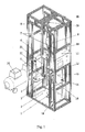
FIG.1 shows a structural schematic diagram of the diagnostic device for detecting the self-lock performance of the differential safety catch of the present invention; -
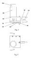
FIG.2 shows a structural schematic diagram of the weight module of the present invention; -
FIG.3 shows a structural schematic diagram of the releaser of the present invention; -
FIG.4 shows a structural schematic diagram of a front view of the releaser of the present invention; -
FIG.5 shows a structural schematic diagram of a plan view of the releaser of the present invention fromFIG.4 ; -
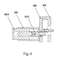
FIG.6 shows a structural schematic diagram of an enlarged section view from A-A dash line direction ofFIG.5 ; -
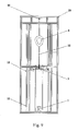
FIG.7 shows a structural schematic diagram of a front view of the diagnostic device for detecting the self-lock performance of the differential safety catch of the present invention; -
FIG.8 shows a structural schematic diagram of the impact base of the present invention; -
FIG.9 shows a schematic diagram of the portable plate when ascending up to the upper limit position; -
FIG.10 shows a schematic diagram of the weight module when falling down as the releaser released it. - With reference now to the drawing, a preferred embodiment of the diagnostic device for detecting the self-lock performance of the differential safety catch of the present invention comprises an
air pump 16, anair cylinder 17, aframe 20, aportable plate 4, areleaser 5, asensor 13 closer to the switch, and animpact base 1, as well as acontrol cabinet 11. - A
hanger ring 19 is fastened with a central hanger plate 8 on top portion of theframe 20, for connecting with adifferential safety catch 9. - The pair of the
mounting plate 10 are oppositely disposed to separated saidframe 20 into upper and lower parts. - On each mounting plate 10 a
bi-directional air cylinder 7, within which anair lever 21 being disposed, is vertically formed. A connectedportable plate 4, at least one of which being arranged with aposition sensor 13, is fastened with lower portion of eachair lever 21 and actuated for a vertical motion with motivation thereof. - Beneath each
mounting plate 10 two gag lever ports ofportable plate 17 and one gag lever port of weight module 6 are individually disposed, wherein the gag lever ports ofportable plate 17 is connected with theportable plate 4 for preventing the skewing thereof during said vertical motion. - Within the
frame 20, one or two upper stop block(s) 12 being disposed below themounting plates 10 is configured to control the upper limit location for the vertically upward motion of theportable plate 4. Within theframe 20, one or two lower stop block(s) 12 being disposed above thebase plate 2 is configured to control the lower limit location for the vertically downward motion of theportable plate 4. - With reference now to
FIG.2 , theweight module 3 include ahanging rod 301, a securingscrew nut 302, a5kg weight block 303 and a plurality of1kg weights 304, the5kg weight block 303 and the1kg weights 304 are configured in circular respectively. Twothru holes 305 configured to be connectedly inserted with the gag lever port of weight module 6 are formed in the peripheral portion of the5kg weight block 303; aopen slot 306 is formed in the1kg weight block 304 for being inserted with the plurality of the1kg weights 304 as needed which being secured by screwing the securingscrew nut 302 up for protecting theweight module 3 from skewing or abjunction. - A pair of gag lever ports of weight module 6 disposed in parallel with the gag lever ports of
portable plate 17 and beneath themounting plate 10 passing through thethru hole 305 of theweight module 3 are configured to prevent the skewing thereof in peripheral orientation during said vertical motion. - Two
releasers 5 being oppositely disposed are disposed respectively on the twoportable plates 4, with reference toFIG.5 and6 , each of which includes aelectromagnet 5010, arelease claw 506 and a leverage, and is configured to connect theelectromagnet 5010 with one side thereof to form a detachable mechanical linkage and therelease jaw 506 with another side thereof that enables therelease jaw 506 vertically vibrating within a certain range while detached from the leverage, and the detachable mechanical linkage formed by theelectromagnet 5010 and the leverage holding theweight module 3 to prevent the fall thereof, respectively, wherein therelease jaw 506 horizontally extends toward the internal central axis of the frame to form a movable planet used for supportingweight module 3. - The mounting plate 8 is fastened with the
bearing 505, thebearing 505 is fastened with theportable plate 4. The leverage includes alever 507,latch 504, and askipjack 503, thelever 507 in connectedly shafted with the mounting plate 8, as well as thebearing 505 through ashaft pin 501 which being fastened with the mounting plate 8, as well as thebearing 505 through abolt 502; anarc groove 5011 of which circle centre being with theshaft pin 501 is formed in thebearing 501, thelatch 504 is configured to connect an end of thelever 507 with its one end and connect an end of theskipjack 503 of which another end being connected with theshaft pin 501, with another end passing through thearc groove 5011. - The
electromagnet 5010 secured within thesleeve 509 is configured to release or link the leverage in correspondence with the instruction from thecabinet 11. Specifically, theelectromagnet 5010 is energized as thecabinet 11 transformed release instruction to cause the iron core actuated, allowing for releasing thelever 507 to release theweight module 3 byrelease claw 506 being switched downwards under the gravity action of theweight module 3. On the contrary, theelectromagnet 5010 is de-energized as thecabinet 11 transformed link instruction to cause the iron core ejected by the action of areset spring 5015, allowing for pressing thelever 507 to holding theweight module 3 up withoutrelease claw 506 being switched downwards, thereby forming a linkage therebetween. - A
position sensor 13 is disposed on theportable plate 4, such as closer to the switch. Theportable plate 4 is actuated for a downward motion with motivation of theair lever 21 as long as theweight module 3 fell down. Theportable plate 4 alters to be actuated for a upward motion as long as thesensor 13 received the signature representative of theweight module 3 during said downward motion, then the release claw of thereleaser 5 instantaneously holds theweight module 3 up and moves up to the upper limit location along with the motion of theportable plate 4. - The
impact base 1 is disposed in central portion of thebase plate 2, of which centre axis, with reference toFIG.7 , is coincided with theweight module 3, as well as thedifferential safety catch 9 thereof. - With reference now to
FIG.8 , theimpact base 1 includes abase 101, acarrier plate 102, abolt 103, andbuffer springs 105, wherein thecarrier plate 102 is embedded into thebase 101, thebolt 103 is connected with thecarrier plate 102 after passing through thebase 101; thebuffer springs 105 are sleeved around thebolt 103 and entrapped between thebase 101 and thecarrier plate 102, descending the impact force from the weights by the buffering generated as said weights falling down to impact thecarrier plate 102. Acount sensor 104 is disposed in one lateral portion of thebase 101 for counting the numbers of falling times of theweight module 3. - The operating process of the diagnostic device of the preferred embodiment in the present invention features as following that
- 1) Fastening the
differential safety catch 9 with thehanger ring 19 of the central hanger plate 8 on top portion of the diagnostic device; - 2) Setting associated detecting parameters in the interface of the
cabinet 11; - 3) Pulling the hanger hook fastened with one end of the safety rope downwards to the lower portion of the
mounting plate 10, and then hanging theweight module 3 to said hook of the safety rope, as shown inFIG.7 ; - 4) activating the
air pump 16 to holding theportable plate 4 up to the upper limit location, and then supporting theweight module 3 by the release claw of thereleaser 5, as shown inFIG.9 ; - 5) The
portable plate 4 being actuated for a downward motion with motivation of theair lever 21 as long as theweight module 3 rapidly fell down, as shown inFIG.10 . Theportable plate 4 alters to be actuated for a upward motion as long as thesensor 13 received the signature representative of theweight module 3 during said downward motion, then the release claw of thereleaser 5 instantaneously holds theweight module 3 up and moves up to the upper limit location along with the motion of theportable plate 4, as shown inFIG.9 ; - 6) It is indicated that the lock mechanism of the
differential safety catch 9 can't be efficiently locked as long as theweight module 3 falling downwards to impact theimpact base 1, the count sensor closer to the switch is configured to count the number of impact. - It will be appreciated that the above-described embodiments are merely illustrative, and that those of ordinary skill in the art may readily devise their own implementations and modifications that incorporate the principles of the present invention and fall within the spirit and scope thereof.
Claims (5)
- A diagnostic device for detecting self-lock performance of a differential safety catch, comprising a base plate 2, an air pump 16, and a frame 20 within which a releaser 5, a pair of mounting plate 10, one or two upper stop block(s) 12, an impact base 1, and a control cabinet 11 being disposed, which is characterized in that
a hanger ring 19 is fastened with a central hanger plate 8 on top portion of the frame 20, for connecting with a differential safety catch 9 of which bottom portion being connected to weight module 3;
the pair of the mounting plate 10 are oppositely disposed to separated said frame 20 into upper and lower parts, on each mounting plate 10 an air cylinder 7, within which an air lever 21 being disposed, is individually formed, a connected portable plate 4, at least one of which being arranged with a position sensor 13, is fastened with lower portion of each air lever 21 and actuated for a vertical motion with motivation thereof;
beneath each mounting plate 10 two gag lever ports of portable plate 17 and one gag lever port of weight module 6 are individually disposed, wherein the gag lever ports of portable plate 17 is connected with the portable plate 4 for preventing the skewing thereof during said vertical motion;
two releasers 5 being oppositely disposed are disposed respectively on the two portable plates 4, each of which includes a electromagnet 5010, a release claw 506 and a leverage, and is configured to connect the electromagnet 5010 with one side thereof to form a detachable mechanical linkage and the release jaw 506 with another side thereof that enables the release jaw 506 vertically vibrating within a certain range while detached from the leverage, and the detachable mechanical linkage formed by the electromagnet 5010 and the leverage holding the weight module 3 to prevent the fall thereof, respectively, wherein the release jaw 506 horizontally extends toward the internal central axis of the frame to form a movable planet used for supporting weight module 3;
the impact base 1 is disposed in central portion of the base plate 2, of which centre axis is coincided with the weight module 3, as well as the differential safety catch 9 thereof, a count sensor 104 is further disposed on said impact base 1. - The diagnostic device for detecting self-lock performance of a differential safety catch of claim 1, wherein within the frame 20, one or two lower stop block(s) 18 are disposed above the base plate 2.
- The diagnostic device for detecting self-lock performance of a differential safety catch of claim 1, wherein the weight module 3 include a hanging rod 301, a securing screw nut 302, a weight block 303 and a plurality of weights 304, the weight block 303 and the weights 304 are configured in circular respectively, two thru holes 305 configured to be connectedly inserted with the gag lever port of weight module 6 are formed in the peripheral portion of the weight block 303; a open slot 306 is formed in the weight block 304 for being inserted with the plurality of the weights 304 as needed which being secured by screwing the securing screw nut 302 up.
- The diagnostic device for detecting self-lock performance of a differential safety catch of claim 1, wherein the releaser 5 further includes a mounting plate 8, a bearing 505, and a sleeve 509, the mounting plate 8 is fastened with the bearing 505, the bearing 505 is fastened with the portable plate 4, the leverage includes a lever 507, latch 504, and a skipjack 503, the lever 507 in connectedly shafted with the mounting plate 8, as well as the bearing 505 through a shaft pin 501 which being fastened with the mounting plate 8, as well as the bearing 505 through a bolt 502; an arc groove 5011 of which circle centre being with the shaft pin 501 is formed in the bearing 501, the latch 504 is configured to connect an end of the lever 507 with its one end and connect an end of the skipjack 503 of which another end being connected with the shaft pin 501, with another end passing through the arc groove 5011; the release claw 506 is secured with the inner port of the lever 507; the sleeve 509 within which the electromagnet 5010 being secured is fastened with mounting plate 8.
- The diagnostic device for detecting self-lock performance of a differential safety catch of anyone of claim 1 to 4, wherein the impact base 1 includes a base 101, a carrier plate 102, a bolt 103, and buffer springs 105, the carrier plate 102 is embedded into the base 101, the bolt 103 is connected with the carrier plate 102 after passing through the base 101; the buffer springs 105 are sleeved around the bolt 103 and entrapped between the base 101 and the carrier plate 102, the count sensor 104 is disposed in one lateral portion of the base 101.
Applications Claiming Priority (2)
| Application Number | Priority Date | Filing Date | Title |
|---|---|---|---|
| CN 201110189045 CN102297762B (en) | 2011-07-06 | 2011-07-06 | Speed-different type safety catcher self-locking reliability performance test machine |
| PCT/CN2012/075012 WO2013004105A1 (en) | 2011-07-06 | 2012-05-03 | Self-locking reliability testing machine for speed difference falling preventing device |
Publications (3)
| Publication Number | Publication Date |
|---|---|
| EP2620758A1 true EP2620758A1 (en) | 2013-07-31 |
| EP2620758A4 EP2620758A4 (en) | 2014-10-29 |
| EP2620758B1 EP2620758B1 (en) | 2019-07-10 |
Family
ID=45358331
Family Applications (1)
| Application Number | Title | Priority Date | Filing Date |
|---|---|---|---|
| EP12808054.6A Active EP2620758B1 (en) | 2011-07-06 | 2012-05-03 | Self-locking reliability testing machine for speed difference falling preventing device |
Country Status (3)
| Country | Link |
|---|---|
| EP (1) | EP2620758B1 (en) |
| CN (1) | CN102297762B (en) |
| WO (1) | WO2013004105A1 (en) |
Cited By (4)
| Publication number | Priority date | Publication date | Assignee | Title |
|---|---|---|---|---|
| CN104034544A (en) * | 2014-05-31 | 2014-09-10 | 邢乃贵 | Structural performance tester |
| CN112255904A (en) * | 2020-10-23 | 2021-01-22 | 苏州吉博斯精密机械有限公司 | Watch impact test fixture |
| CN112880961A (en) * | 2021-02-26 | 2021-06-01 | 北京方正数码有限公司 | Rotary ejection platform and rotary ejection system |
| CN114059757A (en) * | 2021-10-21 | 2022-02-18 | 温州职业技术学院 | A temporary high place climbing frame for civil engineering construction |
Families Citing this family (28)
| Publication number | Priority date | Publication date | Assignee | Title |
|---|---|---|---|---|
| CN102297762B (en) * | 2011-07-06 | 2013-03-13 | 浙江华电器材检测研究所 | Speed-different type safety catcher self-locking reliability performance test machine |
| CN102636340B (en) * | 2012-03-16 | 2014-04-09 | 山东省纺织科学研究院 | Fatigability check meter for movement repeating mechanism of speed difference self-controller |
| CN102840970B (en) * | 2012-08-27 | 2016-03-09 | 江苏申锡建筑机械有限公司 | A kind of fall protection equipment checkout equipment |
| CN103366504B (en) * | 2013-06-26 | 2015-09-02 | 重庆工业设备安装集团有限公司 | Longitudinal-transvedual-lifeline dual-lifeline protection alarm system |
| CN103924777B (en) * | 2014-04-18 | 2016-07-06 | 武汉理工大学 | The decorating outer wall of building special suspension platform of construction |
| CN104062113B (en) * | 2014-06-23 | 2017-01-04 | 浙江华电器材检测研究所 | A kind of catching device self-locking machine for testing reliability |
| CN106185750B (en) * | 2016-08-16 | 2018-09-28 | 太原重型机械集团工程技术研发有限公司 | Elevator and its derricking gear |
| CN107036777A (en) * | 2017-04-18 | 2017-08-11 | 浙江华电器材检测研究所 | Fastener high/low temperature oscillation crosswise testing machine |
| CN107831007B (en) * | 2017-12-12 | 2024-04-30 | 上海市建筑科学研究院科技发展有限公司 | Safety lock detection system for high-altitude operation hanging basket |
| CN108760542B (en) * | 2018-06-14 | 2024-07-12 | 中铁检验认证中心有限公司 | Dynamic fatigue corrosion device for stranded wire |
| CN109236827A (en) * | 2018-11-20 | 2019-01-18 | 张立志 | A kind of axial movement bar Bidirectional locking relieving mechanism |
| CN109573109B (en) * | 2019-01-07 | 2021-10-01 | 哈尔滨工业大学 | A suspended drop test device for rocket recovery |
| CN110608960A (en) * | 2019-09-05 | 2019-12-24 | 北京金辰西维科安全印务有限公司 | A kind of test device and test method |
| CN111764628B (en) * | 2020-07-03 | 2021-09-03 | 中厦建设有限公司 | High-rise building lifting scaffold |
| CN113029448A (en) * | 2021-03-15 | 2021-06-25 | 深圳市云客智慧科技有限公司 | Self-locking mechanism for automobile rear lamp air tightness detection equipment |
| CN113252275B (en) * | 2021-06-29 | 2022-04-05 | 成都九鼎科技(集团)有限公司 | Shock absorber assembly impact testing equipment and testing method |
| CN113418690B (en) * | 2021-07-13 | 2023-09-12 | 江苏省特种设备安全监督检验研究院 | Static simulation test system and test method for anti-fall device of lifting protection platform |
| CN113567099B (en) * | 2021-07-13 | 2023-09-08 | 江苏省特种设备安全监督检验研究院 | Dynamic simulation test system and test method for anti-falling device of lifting protection platform |
| CN113567105B (en) * | 2021-09-01 | 2024-03-12 | 安徽环通工程试验检测有限公司 | Anti-dazzle board low temperature resistant performance testing arrangement that falls |
| CN113820120B (en) * | 2021-11-22 | 2022-02-22 | 枣庄高新区立正安装工程有限公司 | Falling protector testing arrangement |
| CN113984323B (en) * | 2021-11-23 | 2023-12-05 | 江苏华财管道有限公司 | Impact test device of injection molding equipment for plastic pipeline production |
| CN114688949B (en) * | 2022-03-02 | 2023-05-09 | 合肥国轩高科动力能源有限公司 | A device for detecting the flatness of the bottom of a lithium battery module |
| CN115253109B (en) * | 2022-07-27 | 2023-05-12 | 无锡广盈集团有限公司 | Safety rope-distributing hook, safety device and use method of safety device |
| CN115300822B (en) * | 2022-08-15 | 2023-04-14 | 广东电网有限责任公司 | Anti-drop device for high-altitude electric power work |
| CN117387892B (en) * | 2023-10-26 | 2024-03-12 | 四川衡耀复合材料科技有限公司 | Shock resistance testing platform and method for racing bicycle hubs |
| CN117287446B (en) * | 2023-11-22 | 2024-02-13 | 新乡市万和过滤技术股份公司 | Hydraulic cylinder testing system |
| CN118817217B (en) * | 2024-09-20 | 2025-04-01 | 盐城市瑞华机电制造有限公司 | A device for testing the anti-fall performance of a fall arrester |
| CN118913954B (en) * | 2024-10-11 | 2025-08-01 | 佛山市雾雨金属制品有限公司 | Aluminum part quality detection equipment |
Family Cites Families (20)
| Publication number | Priority date | Publication date | Assignee | Title |
|---|---|---|---|---|
| DE2336709C2 (en) * | 1973-07-19 | 1975-01-23 | Wilhelm Fey Maschinen- Und Apparatebau, 6102 Pfundstadt | Drop weight tester for impact testing of ballast and the like |
| DE3138427A1 (en) * | 1981-09-26 | 1983-05-26 | Form + Test Seidner + Co GmbH, 7940 Riedlingen | Device for lifting the drop weight of a soil-testing rig or the like |
| CN1011264B (en) * | 1987-05-22 | 1991-01-16 | 沈阳天平仪器厂 | Automatic lifting packaging bag falling testing machine |
| SU1717516A1 (en) * | 1989-11-27 | 1992-03-07 | Государственный Проектный Институт "Южгипрошахт" | Device for stopping cage of mine tower hoist in testing cage parachute |
| JP3836585B2 (en) * | 1997-11-19 | 2006-10-25 | 株式会社東芝 | Impact test equipment |
| JP3871039B2 (en) * | 2002-05-27 | 2007-01-24 | 日本電気株式会社 | Drop impact tester and drop impact test method |
| US6848293B2 (en) * | 2002-08-23 | 2005-02-01 | Johnson Controls Technology Company | Weight drop system |
| CN2690884Y (en) * | 2003-11-24 | 2005-04-06 | 明门实业股份有限公司 | Reciprocating impact testing machine |
| JP4411284B2 (en) * | 2006-01-16 | 2010-02-10 | 株式会社日立テクノロジ−アンドサ−ビス | Drop test device |
| CN100411965C (en) * | 2006-02-14 | 2008-08-20 | 中国矿业大学 | Device and method for detecting brake performance of fall arrester |
| DE102006015344B4 (en) * | 2006-04-03 | 2008-04-17 | Rüger, Ulrich, Dipl.-Ing. | Simulator for paragliders or surface parachutes |
| CN200995007Y (en) * | 2006-11-08 | 2007-12-26 | 上海森平机械科技有限公司 | High-sensitivity speed-differential safety hook |
| US7555930B2 (en) * | 2007-07-18 | 2009-07-07 | Seagate Technology Llc | Test assembly and method |
| CN100557405C (en) * | 2007-12-27 | 2009-11-04 | 上海市建筑科学研究院(集团)有限公司 | Detection and test equipment for anti-drop safety protection device of gear type construction hoist |
| CN100580411C (en) * | 2008-01-31 | 2010-01-13 | 上海市建筑科学研究院(集团)有限公司 | Hanging basket safety lock and wire rope elevator broken rope protection device detection test equipment |
| US8490750B2 (en) * | 2008-02-25 | 2013-07-23 | Honeywell International Inc. | Energy absorbing lifeline systems |
| CN201392297Y (en) * | 2009-04-17 | 2010-01-27 | 武汉凯盟机电有限公司 | Falling hammer impact testing machine |
| CN201653670U (en) * | 2010-01-18 | 2010-11-24 | 浙江电力职业技术学院 | Multifunctional falling-preventing apparatus experiment tower |
| CN102297762B (en) * | 2011-07-06 | 2013-03-13 | 浙江华电器材检测研究所 | Speed-different type safety catcher self-locking reliability performance test machine |
| CN202158948U (en) * | 2011-07-06 | 2012-03-07 | 浙江华电器材检测研究所 | Self-locking reliability test machine for speed difference safety catcher |
-
2011
- 2011-07-06 CN CN 201110189045 patent/CN102297762B/en active Active
-
2012
- 2012-05-03 WO PCT/CN2012/075012 patent/WO2013004105A1/en not_active Ceased
- 2012-05-03 EP EP12808054.6A patent/EP2620758B1/en active Active
Cited By (6)
| Publication number | Priority date | Publication date | Assignee | Title |
|---|---|---|---|---|
| CN104034544A (en) * | 2014-05-31 | 2014-09-10 | 邢乃贵 | Structural performance tester |
| CN112255904A (en) * | 2020-10-23 | 2021-01-22 | 苏州吉博斯精密机械有限公司 | Watch impact test fixture |
| CN112880961A (en) * | 2021-02-26 | 2021-06-01 | 北京方正数码有限公司 | Rotary ejection platform and rotary ejection system |
| CN112880961B (en) * | 2021-02-26 | 2023-06-13 | 中国民航管理干部学院 | A rotary ejection platform and a rotary ejection system |
| CN114059757A (en) * | 2021-10-21 | 2022-02-18 | 温州职业技术学院 | A temporary high place climbing frame for civil engineering construction |
| CN114059757B (en) * | 2021-10-21 | 2023-06-09 | 温州职业技术学院 | Civil engineering construction is with interim eminence climbing frame |
Also Published As
| Publication number | Publication date |
|---|---|
| EP2620758A4 (en) | 2014-10-29 |
| CN102297762A (en) | 2011-12-28 |
| EP2620758B1 (en) | 2019-07-10 |
| WO2013004105A1 (en) | 2013-01-10 |
| CN102297762B (en) | 2013-03-13 |
Similar Documents
| Publication | Publication Date | Title |
|---|---|---|
| EP2620758B1 (en) | Self-locking reliability testing machine for speed difference falling preventing device | |
| CN206515167U (en) | High speed drop hammer impact testing machine | |
| CN105501452B (en) | A kind of helicopter goods hooking device and its method and control method | |
| CN104062113B (en) | A kind of catching device self-locking machine for testing reliability | |
| CN105387983B (en) | A kind of battery detecting heavy impact device | |
| CN203981515U (en) | A kind of anti-secondary pulse device of skeleton symbol drop hammer impact testing machine | |
| ATE501033T1 (en) | Method for jettisoning an external load carried by an aircraft and its associated device | |
| CN203981386U (en) | A kind of safety catcher self-locking machine for testing reliability | |
| CN209802891U (en) | Clamp type clamp impact and brake cable fatigue machine testing machine | |
| CN202158948U (en) | Self-locking reliability test machine for speed difference safety catcher | |
| CN203672644U (en) | Multifunctional safety lock test bench | |
| CN1325362C (en) | Rope brake for overspeed upgoing elevator | |
| CN102998076B (en) | A device for measuring the impact of falling off heavy objects | |
| CN205785742U (en) | A kind of drop machine expanding unit | |
| KR102158489B1 (en) | Extraction device of the blower | |
| CN104627828A (en) | Unhooking control method, equipment and system of loaded lowering device and engineering machinery | |
| CN105667800A (en) | Rope transfer device for unmanned helicopter and unmanned helicopter | |
| CN202075188U (en) | Breakage testing machine | |
| CN102849074A (en) | Intelligent runaway prevention retaining chair device for ropeway | |
| CN202142236U (en) | safety gear | |
| CN211263023U (en) | Load detection equipment | |
| CN105477796A (en) | High-rise-building safe escaping device | |
| CN207540758U (en) | A kind of medium-sized shock machine of pendulum | |
| CN215768055U (en) | Solidification experiment table for solid concrete research and development based on steel industry | |
| CN215894232U (en) | Chip lithography machine display test machine |
Legal Events
| Date | Code | Title | Description |
|---|---|---|---|
| PUAI | Public reference made under article 153(3) epc to a published international application that has entered the european phase |
Free format text: ORIGINAL CODE: 0009012 |
|
| 17P | Request for examination filed |
Effective date: 20130423 |
|
| AK | Designated contracting states |
Kind code of ref document: A1 Designated state(s): AL AT BE BG CH CY CZ DE DK EE ES FI FR GB GR HR HU IE IS IT LI LT LU LV MC MK MT NL NO PL PT RO RS SE SI SK SM TR |
|
| DAX | Request for extension of the european patent (deleted) | ||
| A4 | Supplementary search report drawn up and despatched |
Effective date: 20140926 |
|
| RIC1 | Information provided on ipc code assigned before grant |
Ipc: G01M 99/00 20110101AFI20140922BHEP Ipc: G01M 7/08 20060101ALI20140922BHEP Ipc: A62B 1/08 20060101ALI20140922BHEP |
|
| 17Q | First examination report despatched |
Effective date: 20160826 |
|
| STAA | Information on the status of an ep patent application or granted ep patent |
Free format text: STATUS: EXAMINATION IS IN PROGRESS |
|
| GRAP | Despatch of communication of intention to grant a patent |
Free format text: ORIGINAL CODE: EPIDOSNIGR1 |
|
| STAA | Information on the status of an ep patent application or granted ep patent |
Free format text: STATUS: GRANT OF PATENT IS INTENDED |
|
| INTG | Intention to grant announced |
Effective date: 20181002 |
|
| GRAS | Grant fee paid |
Free format text: ORIGINAL CODE: EPIDOSNIGR3 |
|
| RAP1 | Party data changed (applicant data changed or rights of an application transferred) |
Owner name: ZHEJIANG HUADIAN EQUIPMENT TESTING INSTITUTE |
|
| GRAA | (expected) grant |
Free format text: ORIGINAL CODE: 0009210 |
|
| STAA | Information on the status of an ep patent application or granted ep patent |
Free format text: STATUS: THE PATENT HAS BEEN GRANTED |
|
| AK | Designated contracting states |
Kind code of ref document: B1 Designated state(s): AL AT BE BG CH CY CZ DE DK EE ES FI FR GB GR HR HU IE IS IT LI LT LU LV MC MK MT NL NO PL PT RO RS SE SI SK SM TR |
|
| REG | Reference to a national code |
Ref country code: GB Ref legal event code: FG4D |
|
| REG | Reference to a national code |
Ref country code: CH Ref legal event code: EP Ref country code: AT Ref legal event code: REF Ref document number: 1154094 Country of ref document: AT Kind code of ref document: T Effective date: 20190715 |
|
| REG | Reference to a national code |
Ref country code: DE Ref legal event code: R096 Ref document number: 602012061950 Country of ref document: DE |
|
| REG | Reference to a national code |
Ref country code: IE Ref legal event code: FG4D |
|
| REG | Reference to a national code |
Ref country code: NL Ref legal event code: MP Effective date: 20190710 |
|
| REG | Reference to a national code |
Ref country code: LT Ref legal event code: MG4D |
|
| REG | Reference to a national code |
Ref country code: AT Ref legal event code: MK05 Ref document number: 1154094 Country of ref document: AT Kind code of ref document: T Effective date: 20190710 |
|
| PG25 | Lapsed in a contracting state [announced via postgrant information from national office to epo] |
Ref country code: NO Free format text: LAPSE BECAUSE OF FAILURE TO SUBMIT A TRANSLATION OF THE DESCRIPTION OR TO PAY THE FEE WITHIN THE PRESCRIBED TIME-LIMIT Effective date: 20191010 Ref country code: BG Free format text: LAPSE BECAUSE OF FAILURE TO SUBMIT A TRANSLATION OF THE DESCRIPTION OR TO PAY THE FEE WITHIN THE PRESCRIBED TIME-LIMIT Effective date: 20191010 Ref country code: SE Free format text: LAPSE BECAUSE OF FAILURE TO SUBMIT A TRANSLATION OF THE DESCRIPTION OR TO PAY THE FEE WITHIN THE PRESCRIBED TIME-LIMIT Effective date: 20190710 Ref country code: AT Free format text: LAPSE BECAUSE OF FAILURE TO SUBMIT A TRANSLATION OF THE DESCRIPTION OR TO PAY THE FEE WITHIN THE PRESCRIBED TIME-LIMIT Effective date: 20190710 Ref country code: LT Free format text: LAPSE BECAUSE OF FAILURE TO SUBMIT A TRANSLATION OF THE DESCRIPTION OR TO PAY THE FEE WITHIN THE PRESCRIBED TIME-LIMIT Effective date: 20190710 Ref country code: HR Free format text: LAPSE BECAUSE OF FAILURE TO SUBMIT A TRANSLATION OF THE DESCRIPTION OR TO PAY THE FEE WITHIN THE PRESCRIBED TIME-LIMIT Effective date: 20190710 Ref country code: PT Free format text: LAPSE BECAUSE OF FAILURE TO SUBMIT A TRANSLATION OF THE DESCRIPTION OR TO PAY THE FEE WITHIN THE PRESCRIBED TIME-LIMIT Effective date: 20191111 Ref country code: NL Free format text: LAPSE BECAUSE OF FAILURE TO SUBMIT A TRANSLATION OF THE DESCRIPTION OR TO PAY THE FEE WITHIN THE PRESCRIBED TIME-LIMIT Effective date: 20190710 Ref country code: FI Free format text: LAPSE BECAUSE OF FAILURE TO SUBMIT A TRANSLATION OF THE DESCRIPTION OR TO PAY THE FEE WITHIN THE PRESCRIBED TIME-LIMIT Effective date: 20190710 |
|
| PG25 | Lapsed in a contracting state [announced via postgrant information from national office to epo] |
Ref country code: ES Free format text: LAPSE BECAUSE OF FAILURE TO SUBMIT A TRANSLATION OF THE DESCRIPTION OR TO PAY THE FEE WITHIN THE PRESCRIBED TIME-LIMIT Effective date: 20190710 Ref country code: GR Free format text: LAPSE BECAUSE OF FAILURE TO SUBMIT A TRANSLATION OF THE DESCRIPTION OR TO PAY THE FEE WITHIN THE PRESCRIBED TIME-LIMIT Effective date: 20191011 Ref country code: IS Free format text: LAPSE BECAUSE OF FAILURE TO SUBMIT A TRANSLATION OF THE DESCRIPTION OR TO PAY THE FEE WITHIN THE PRESCRIBED TIME-LIMIT Effective date: 20191110 Ref country code: RS Free format text: LAPSE BECAUSE OF FAILURE TO SUBMIT A TRANSLATION OF THE DESCRIPTION OR TO PAY THE FEE WITHIN THE PRESCRIBED TIME-LIMIT Effective date: 20190710 Ref country code: AL Free format text: LAPSE BECAUSE OF FAILURE TO SUBMIT A TRANSLATION OF THE DESCRIPTION OR TO PAY THE FEE WITHIN THE PRESCRIBED TIME-LIMIT Effective date: 20190710 Ref country code: LV Free format text: LAPSE BECAUSE OF FAILURE TO SUBMIT A TRANSLATION OF THE DESCRIPTION OR TO PAY THE FEE WITHIN THE PRESCRIBED TIME-LIMIT Effective date: 20190710 |
|
| PG25 | Lapsed in a contracting state [announced via postgrant information from national office to epo] |
Ref country code: TR Free format text: LAPSE BECAUSE OF FAILURE TO SUBMIT A TRANSLATION OF THE DESCRIPTION OR TO PAY THE FEE WITHIN THE PRESCRIBED TIME-LIMIT Effective date: 20190710 |
|
| PG25 | Lapsed in a contracting state [announced via postgrant information from national office to epo] |
Ref country code: IT Free format text: LAPSE BECAUSE OF FAILURE TO SUBMIT A TRANSLATION OF THE DESCRIPTION OR TO PAY THE FEE WITHIN THE PRESCRIBED TIME-LIMIT Effective date: 20190710 Ref country code: RO Free format text: LAPSE BECAUSE OF FAILURE TO SUBMIT A TRANSLATION OF THE DESCRIPTION OR TO PAY THE FEE WITHIN THE PRESCRIBED TIME-LIMIT Effective date: 20190710 Ref country code: DK Free format text: LAPSE BECAUSE OF FAILURE TO SUBMIT A TRANSLATION OF THE DESCRIPTION OR TO PAY THE FEE WITHIN THE PRESCRIBED TIME-LIMIT Effective date: 20190710 Ref country code: EE Free format text: LAPSE BECAUSE OF FAILURE TO SUBMIT A TRANSLATION OF THE DESCRIPTION OR TO PAY THE FEE WITHIN THE PRESCRIBED TIME-LIMIT Effective date: 20190710 Ref country code: PL Free format text: LAPSE BECAUSE OF FAILURE TO SUBMIT A TRANSLATION OF THE DESCRIPTION OR TO PAY THE FEE WITHIN THE PRESCRIBED TIME-LIMIT Effective date: 20190710 |
|
| PG25 | Lapsed in a contracting state [announced via postgrant information from national office to epo] |
Ref country code: IS Free format text: LAPSE BECAUSE OF FAILURE TO SUBMIT A TRANSLATION OF THE DESCRIPTION OR TO PAY THE FEE WITHIN THE PRESCRIBED TIME-LIMIT Effective date: 20200224 Ref country code: SK Free format text: LAPSE BECAUSE OF FAILURE TO SUBMIT A TRANSLATION OF THE DESCRIPTION OR TO PAY THE FEE WITHIN THE PRESCRIBED TIME-LIMIT Effective date: 20190710 Ref country code: SM Free format text: LAPSE BECAUSE OF FAILURE TO SUBMIT A TRANSLATION OF THE DESCRIPTION OR TO PAY THE FEE WITHIN THE PRESCRIBED TIME-LIMIT Effective date: 20190710 Ref country code: CZ Free format text: LAPSE BECAUSE OF FAILURE TO SUBMIT A TRANSLATION OF THE DESCRIPTION OR TO PAY THE FEE WITHIN THE PRESCRIBED TIME-LIMIT Effective date: 20190710 |
|
| REG | Reference to a national code |
Ref country code: DE Ref legal event code: R097 Ref document number: 602012061950 Country of ref document: DE |
|
| PLBE | No opposition filed within time limit |
Free format text: ORIGINAL CODE: 0009261 |
|
| STAA | Information on the status of an ep patent application or granted ep patent |
Free format text: STATUS: NO OPPOSITION FILED WITHIN TIME LIMIT |
|
| PG2D | Information on lapse in contracting state deleted |
Ref country code: IS |
|
| 26N | No opposition filed |
Effective date: 20200603 |
|
| PG25 | Lapsed in a contracting state [announced via postgrant information from national office to epo] |
Ref country code: SI Free format text: LAPSE BECAUSE OF FAILURE TO SUBMIT A TRANSLATION OF THE DESCRIPTION OR TO PAY THE FEE WITHIN THE PRESCRIBED TIME-LIMIT Effective date: 20190710 |
|
| REG | Reference to a national code |
Ref country code: DE Ref legal event code: R119 Ref document number: 602012061950 Country of ref document: DE |
|
| PG25 | Lapsed in a contracting state [announced via postgrant information from national office to epo] |
Ref country code: LI Free format text: LAPSE BECAUSE OF NON-PAYMENT OF DUE FEES Effective date: 20200531 Ref country code: CH Free format text: LAPSE BECAUSE OF NON-PAYMENT OF DUE FEES Effective date: 20200531 Ref country code: MC Free format text: LAPSE BECAUSE OF FAILURE TO SUBMIT A TRANSLATION OF THE DESCRIPTION OR TO PAY THE FEE WITHIN THE PRESCRIBED TIME-LIMIT Effective date: 20190710 |
|
| REG | Reference to a national code |
Ref country code: BE Ref legal event code: MM Effective date: 20200531 |
|
| GBPC | Gb: european patent ceased through non-payment of renewal fee |
Effective date: 20200503 |
|
| PG25 | Lapsed in a contracting state [announced via postgrant information from national office to epo] |
Ref country code: LU Free format text: LAPSE BECAUSE OF NON-PAYMENT OF DUE FEES Effective date: 20200503 |
|
| PG25 | Lapsed in a contracting state [announced via postgrant information from national office to epo] |
Ref country code: FR Free format text: LAPSE BECAUSE OF NON-PAYMENT OF DUE FEES Effective date: 20200531 Ref country code: GB Free format text: LAPSE BECAUSE OF NON-PAYMENT OF DUE FEES Effective date: 20200503 Ref country code: IE Free format text: LAPSE BECAUSE OF NON-PAYMENT OF DUE FEES Effective date: 20200503 |
|
| PG25 | Lapsed in a contracting state [announced via postgrant information from national office to epo] |
Ref country code: DE Free format text: LAPSE BECAUSE OF NON-PAYMENT OF DUE FEES Effective date: 20201201 Ref country code: BE Free format text: LAPSE BECAUSE OF NON-PAYMENT OF DUE FEES Effective date: 20200531 |
|
| PG25 | Lapsed in a contracting state [announced via postgrant information from national office to epo] |
Ref country code: MT Free format text: LAPSE BECAUSE OF FAILURE TO SUBMIT A TRANSLATION OF THE DESCRIPTION OR TO PAY THE FEE WITHIN THE PRESCRIBED TIME-LIMIT Effective date: 20190710 Ref country code: CY Free format text: LAPSE BECAUSE OF FAILURE TO SUBMIT A TRANSLATION OF THE DESCRIPTION OR TO PAY THE FEE WITHIN THE PRESCRIBED TIME-LIMIT Effective date: 20190710 |
|
| PG25 | Lapsed in a contracting state [announced via postgrant information from national office to epo] |
Ref country code: MK Free format text: LAPSE BECAUSE OF FAILURE TO SUBMIT A TRANSLATION OF THE DESCRIPTION OR TO PAY THE FEE WITHIN THE PRESCRIBED TIME-LIMIT Effective date: 20190710 |