EP2620257A1 - Automatic correction method for processing size of glass plate, and glass plate processing device - Google Patents
Automatic correction method for processing size of glass plate, and glass plate processing device Download PDFInfo
- Publication number
- EP2620257A1 EP2620257A1 EP11826528.9A EP11826528A EP2620257A1 EP 2620257 A1 EP2620257 A1 EP 2620257A1 EP 11826528 A EP11826528 A EP 11826528A EP 2620257 A1 EP2620257 A1 EP 2620257A1
- Authority
- EP
- European Patent Office
- Prior art keywords
- grinding
- cutting
- plate
- glass
- glass plate
- Prior art date
- Legal status (The legal status is an assumption and is not a legal conclusion. Google has not performed a legal analysis and makes no representation as to the accuracy of the status listed.)
- Withdrawn
Links
Images


Classifications
-
- B—PERFORMING OPERATIONS; TRANSPORTING
- B24—GRINDING; POLISHING
- B24B—MACHINES, DEVICES, OR PROCESSES FOR GRINDING OR POLISHING; DRESSING OR CONDITIONING OF ABRADING SURFACES; FEEDING OF GRINDING, POLISHING, OR LAPPING AGENTS
- B24B9/00—Machines or devices designed for grinding edges or bevels on work or for removing burrs; Accessories therefor
- B24B9/02—Machines or devices designed for grinding edges or bevels on work or for removing burrs; Accessories therefor characterised by a special design with respect to properties of materials specific to articles to be ground
- B24B9/06—Machines or devices designed for grinding edges or bevels on work or for removing burrs; Accessories therefor characterised by a special design with respect to properties of materials specific to articles to be ground of non-metallic inorganic material, e.g. stone, ceramics, porcelain
- B24B9/08—Machines or devices designed for grinding edges or bevels on work or for removing burrs; Accessories therefor characterised by a special design with respect to properties of materials specific to articles to be ground of non-metallic inorganic material, e.g. stone, ceramics, porcelain of glass
- B24B9/10—Machines or devices designed for grinding edges or bevels on work or for removing burrs; Accessories therefor characterised by a special design with respect to properties of materials specific to articles to be ground of non-metallic inorganic material, e.g. stone, ceramics, porcelain of glass of plate glass
-
- B—PERFORMING OPERATIONS; TRANSPORTING
- B24—GRINDING; POLISHING
- B24B—MACHINES, DEVICES, OR PROCESSES FOR GRINDING OR POLISHING; DRESSING OR CONDITIONING OF ABRADING SURFACES; FEEDING OF GRINDING, POLISHING, OR LAPPING AGENTS
- B24B41/00—Component parts such as frames, beds, carriages, headstocks
- B24B41/005—Feeding or manipulating devices specially adapted to grinding machines
-
- B—PERFORMING OPERATIONS; TRANSPORTING
- B24—GRINDING; POLISHING
- B24B—MACHINES, DEVICES, OR PROCESSES FOR GRINDING OR POLISHING; DRESSING OR CONDITIONING OF ABRADING SURFACES; FEEDING OF GRINDING, POLISHING, OR LAPPING AGENTS
- B24B49/00—Measuring or gauging equipment for controlling the feed movement of the grinding tool or work; Arrangements of indicating or measuring equipment, e.g. for indicating the start of the grinding operation
- B24B49/12—Measuring or gauging equipment for controlling the feed movement of the grinding tool or work; Arrangements of indicating or measuring equipment, e.g. for indicating the start of the grinding operation involving optical means
Definitions
- the present invention relates to a method of automatically measuring and correcting processing dimensions in a glass-plate working apparatus for manufacturing such as glass plates for window glass of automobiles, glass plates for liquid crystal displays, and glass plates for furniture from unshaped plate glass by subjecting it to cutting and grinding work, as well as a glass-plate working apparatus equipped with an automatic measuring device.
- the present invention concerns a method in which, in a glass-plate working apparatus equipped with a cutting section, a grinding work section, and a glass-plate transporting device and adapted to transport a cut glass plate from the cutting section to the grinding work section by the glass-plate transporting device and effect the grinding work of cut end faces in this grinding work section, the position of the cut glass plate transported and processing dimensions of cutting and grinding work are automatically measured, and are automatically corrected on the basis of the measured values.
- the present invention relates to a method of automatically measuring and correcting processing dimensions in a glass-plate working apparatus with the aforementioned cutting section, grinding work section, and glass-plate transporting device operated by being NC controlled by a computer numerical controller, as well as a glass-plate working apparatus equipped with an automatic measuring device.
- a computer numerical controller will be hereinafter referred to as the CNC device.
- the present invention concerns a method in which, in a glass-plate working apparatus equipped with a cutting section, a grinding work section, and a glass-plate transporting device and adapted to cut (form cut lines in and bend-break) a glass plate in the cutting section by NC controlling a cutting head having a cutter wheel or the cutting head and a glass-plate supporting base with the glass plate placed thereon, transport the cut glass plate under NC control from the glass-plate supporting base of this cutting section to a glass-plate supporting base of the grinding work section by the glass-plate transporting device, and effect the grinding work of end faces of the cut glass plate in this grinding work section by NC controlling both a grinding head having a grinding wheel and the glass-plate supporting base with the cut glass plate placed and fixed thereon, the position, cutting work dimensions, and grinding work dimensions of the cut glass plate transported are automatically measured, and the processing dimensions are automatically corrected on the basis of the measured values.
- the present invention concerns a method in which, in a glass-plate working apparatus equipped with a cutting section, a bend-breaking section, a grinding work section, and a glass-plate transporting device and adapted to form cut lines in a glass plate in the cutting section by NC controlling a cutting head having a cutter wheel or the cutting head and a glass-plate supporting base with the glass plate held thereon, transport under NC control this glass plate with the cut lines formed thereon from the glass-plate supporting base of the cutting section to the bend-breaking section by the aforementioned glass-plate transporting device, bend-break the glass plate along the aforementioned cut lines in this bend-breaking section to obtain a cut glass plate, transport this cut glass plate from this bend-breaking section to a glass-plate supporting base of the grinding work section by the aforementioned glass-plate transporting means under numerical control, and effect the grinding work of end faces of the cut glass plate in this grinding work section by NC controlling both a grinding head having a grinding wheel and the glass-plate supporting base with the cut glass plate placed and fixed thereon
- the glass-plate supporting base of the aforementioned cutting section will be referred to as a cutting table
- the glass-plate supporting base of the grinding work section will be referred to as a grinding table.
- a glass-plate working apparatus described in International Publication No. WO2004/039538 is known as a glass-plate working method and a glass-plate working apparatus in which a cut glass plate which has been transported from the cutting section to the grinding work section through the bend-breaking section is subjected to grinding work in this grinding work section, the processing dimensions of the glass plate thus subjected to grinding work are automatically measured, and the cutting depth of the grinding wheel is automatically corrected on the basis of this measured value.
- This glass-plate working apparatus includes a cut-line forming means for forming a cut line on the glass plate; a bend-breaking means for bend-breaking along the cut line the glass plate with the cut line formed thereon by the cut-line forming means; a grinding means having a disk-shaped grinding wheel for grinding peripheral edges of the glass plate bend-broken by the bend-breaking means by coming into contact with the peripheral edges; a detecting means for detecting the position of the peripheral edge of the glass plate ground by the grinding means; a setting means for setting a set value (reference value) indicating a desired position of the peripheral edge of the glass plate ground by the grinding means; a correcting means for correcting the position of the grinding wheel with respect to the arriving glass plate on the basis of a detected value indicating the position of the peripheral edge of the glass plate detected by the detecting means and a set value set in advance by the setting means; and a transporting means for transporting the glass plate sequentially to the cut-line forming means, the bend-breaking means, and the grinding means.
- this is a method in which the amount of wear of the grinding wheel is measured by detecting the position of the peripheral edge of the ground glass plate, and the position of the grinding wheel is corrected on the basis of this measured amount of wear.
- this is a method in which, in the correcting step, a deviation value between a detected value indicating the position of the peripheral edge of the ground glass plate and a preset value is determined, and the position of the grinding wheel is corrected on the basis of the determined deviation value.
- the present invention has been devised in view of the above-described drawbacks of the conventional glass-plate working apparatus, and its object is to provide a method of automatically measuring and correcting processing dimensions of a glass plate and a glass-plate working apparatus, which make it possible to effect automatic measurement and correction of processing dimensions of a cut glass plate and a ground glass plate in processing production and effect automatic measurement and correction of the transported position of the glass plate which is transported from the cutting section to the grinding work section.
- a method of automatically correcting a grinding dimension of a glass plate comprising the steps of: measuring a position of one side in a transporting direction of a cut glass plate which has been transported from a cutting section to a grinding work section by a glass-plate transporting device; making a comparison between a measured value thereof and a preset value set in a CNC device for numerically controlling the transporting operation of the glass-plate transporting device; and in a case where a difference between the measured value and the preset value is due to the thermal displacement of the glass-plate transporting device, correcting the preset value on the basis of the difference, and in a case where the difference is due to a cutting error, setting the difference as an offset value in the CNC device.
- a method of automatically correcting a processing dimension in a glass-plate working apparatus in which a glass plate is cut in a cutting section by NC controlling by a CNC device a cutting head having a cutter wheel or the cutting head and a cutting table holding the glass plate, the cut glass plate is transported from the cutting table of the cutting section to a grinding table of a grinding work section by a glass-plate transporting device, and an end face of the cut glass plate is subjected to grinding work in the grinding work section by NC controlling by the CNC device the grinding table and the grinding head having the grinding wheel, comprising the steps of: installing in the grinding work section a laser measuring instrument for measuring by laser light a position of one side in a transporting direction of the cut glass plate placed on the grinding table; and implementing the following first to fifth steps: a first step in which the glass-plate working apparatus is operated, and the cut glass plate is transported to and placed on the grinding table of the grinding work section from the cutting section; a second step in which the position of
- a method of automatically correcting a processing dimension in the above-described glass-plate working apparatus comprising the steps of: installing in the grinding work section a laser measuring instrument for measuring by laser light a position of one side in a transporting direction of the cut glass plate placed on the grinding table; and implementing the following first to fifth steps: a first step in which the glass-plate working apparatus is operated, and the cut glass plate is transported to and placed on the grinding table of the grinding work section from the cutting section; a second step in which the position of the one side in the transporting direction of the cut glass plate is measured by the laser measuring instrument; a third step in which the glass-plate working apparatus is operated to effect the grinding work of the cut glass plate, and upon completion of the grinding work the position of the one side in the transporting direction of that ground glass plate is measured again by the laser measuring instrument to obtain a measured value; a fourth step in which a comparison is made between the measured value after the completion of the grinding work and a grinding target value obtained by
- a method of automatically correcting a processing method in the above-described glass-plate working apparatus comprising the steps of: installing in the grinding work section a laser measuring instrument for measuring by laser light a position of one side in a transporting direction of the glass plate placed on the grinding table; and implementing the following first to fifth steps: a first step in which the glass-plate working apparatus is operated, and the cut glass plate is transported to and placed on the grinding table of the grinding work section from the cutting section; a second step in which the position of the one side in the transporting direction of the cut glass plate is measured by the laser measuring instrument; a third step in which a comparison is made between a measured value obtained by the laser measuring instrument and a preset value set in the CNC device, and when they differ, an error value thereof is calculated; a fourth step in which, on the basis of a thermal displacement amount value of the glass-plate transporting device set in the CNC device, a determination is made as to whether the error value is due to the thermal displacement of
- a method of automatically correcting a processing dimension in the above-described glass-plate working apparatus comprising the steps of: installing in the grinding work section a laser measuring instrument for measuring by laser light a position of one side in a transporting direction of the glass plate placed on the grinding table; and implementing the following first to ninth steps: a first step in which the glass-plate working apparatus is operated, and the cut glass plate is transported to and placed on the grinding table of the grinding work section from the cutting section; a second step in which the position of the one side in the transporting direction of the cut glass plate is measured by the laser measuring instrument; a third step in which a comparison is made between a measured value obtained by the laser measuring instrument and a preset value set in the CNC device, and when they differ, an error value thereof is calculated; a fourth step in which, on the basis of a thermal displacement amount value of the glass-plate transporting device set in the CNC device, a determination is made as to whether the error value is due to the thermal displacement of
- a method of automatically correcting a processing method in a glass-plate working apparatus in which a cut line is formed on a glass plate in a cutting section by NC controlling by a CNC device a cutting head having a cutter wheel and a cutting table holding the glass plate, the glass plate with the cut line formed thereon is transported from the cutting table of the cutting section to a bend-breaking section by a glass-plate transporting device under NC control, the glass plate with the cut line formed thereon is bend-broken in the bend-breaking section to obtain a cut glass plate, the cut glass plate is transported from the bend-breaking section to a grinding table of a grinding work section by the glass-plate transporting device under NC control, and an end face of the cut glass plate is subjected to grinding work in the grinding work section by NC controlling by the CNC device the grinding table and the grinding head having the grinding wheel, comprising the steps of: installing in the grinding work section a laser measuring instrument for measuring by laser light a position of one side in a transporting direction
- a method of automatically correcting a processing dimension in the above-described glass-plate working apparatus comprising the steps of: installing in the grinding work section a laser measuring instrument for measuring by laser light a position of one side in a transporting direction of the glass plate placed on the grinding table; and implementing the following first to ninth steps: a first step in which the glass-plate working apparatus is operated, and the cut glass plate is transported to and placed on the grinding table of the grinding work section from the cutting section via the bend-breaking section; a second step in which the position of the one side in the transporting direction of the cut glass plate is measured by the laser measuring instrument; a third step in which a comparison is made between a measured value obtained by the laser measuring instrument and a preset value set in the CNC device, and when they differ, an error value thereof is calculated; a fourth step in which, on the basis of a thermal displacement amount value of the glass-plate transporting device set in the CNC device, a determination is made as to whether the error value is due
- a glass-plate working apparatus comprising: a cutting section for cutting a glass plate; a grinding work section for effecting grinding work of an end face of the cut glass plate; a glass-plate transporting device for transporting the cut glass plate cut in the cutting section from the cutting section to the grinding work section; a CNC device for NC controlling the operation of cutting the glass plate in the cutting section, the operation of grinding the cut glass plate in the grinding work section, and the transporting operation of the glass-plate transporting device, respectively; and a laser measuring instrument for measuring by laser light a position of one side in a transporting direction of the glass plate in the grinding work section, wherein a comparison is made between a measured value based on the laser measuring instrument and a preset value set in the CNC device, and the preset value is corrected or an offset value is set on the basis of a difference between the measured value and the preset value.
- a glass-plate working apparatus in which a glass plate is cut in a cutting section by NC controlling by a CNC device a cutting head having a cutter wheel or the cutting head and a cutting table holding the glass plate, the cut glass plate is transported from the cutting table of the cutting section to a grinding table of a grinding work section by a glass-plate transporting device, and an end face of the cut glass plate is subjected to grinding work in the grinding work section by NC controlling by the CNC device the grinding table and the grinding head having the grinding wheel, comprising: a laser measuring instrument installed in the grinding work section so as to be able to measure by laser light a position of one side in a glass plate transporting direction of a cut glass plate or a ground glass plate placed on the grinding table.
- the laser measuring instrument is installed in the grinding work section such that the position of one side in the transporting direction of the cut glass plate placed on the grinding table can be measured by laser light, and the position of the one side in the transporting direction of the cut glass plate transported from the cutting section to and placed on the grinding table of the grinding work section is measured by the laser measuring instrument.
- a comparison is made between this measured value and a preset value, and thus in a case where there is no difference (the measured value is within an allowance), it is determined that the cut glass plate has been processed to an as-designed cutting dimension and placed at an as-designed accurate position on the grinding table.
- the measured value and the set value differ, it is possible to easily determine on the basis of a thermal displacement amount value of the glass-plate transporting device set in the CNC device whether that difference is due to the thermal displacement of the glass-plate transporting device or due to a cutting error in the cutting section, for instance, in a case where a thermal displacement amount value of the glass-plate transporting device set in the CNC device is numeric other than zero, zero, or blank.
- the transporting and placing position of the cut glass plate is automatically corrected by correcting and setting the thermal displacement amount value in the CNC device, whereas in the case where the difference is due to a cutting error, the processing dimension of the cut glass plate is automatically corrected by setting that difference as an offset value in the CNC device.
- the cut glass plate with the as-designed accurate processing dimension is placed accurately at an as-designed position on the grinding table of the grinding work section.
- the presence or absence of the escape of the grinding wheel due to a grinding load can be easily determined by grinding the cut glass plate cut to as-designed cutting dimension and placed at an as-designed accurate position on the grinding table, by measuring again by the aforementioned laser measuring instrument the position of the one side in the transporting direction of that ground glass plate, and by making a comparison between that measured value and a value obtained by incorporating a set cutting depth value of the grinding wheel into the measured value of that cut glass plate.
- the cutting depth of the grinding wheel is corrected on the basis of the aforementioned error value, thereby making it possible to easily effect automatic correction of the processing dimension of the ground glass plate.
- the glass-plate grinding method in the grinding work section may be a grinding method of polar coordinate control in which the grinding table for placing and fixing the glass plate is rotated under numeral control, while the grinding head and, hence, the grinding wheel are advanced or retracted under numerical control with respect to the grinding table, and the grinding wheel is brought into contact with and made to follow a peripheral edge of the rotating glass plate, to thereby effect grinding work.
- the drawings show a glass-plate working apparatus in accordance with an embodiment of the present invention.
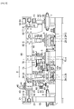
- Figs. 1 to 6 show the present glass-plate working apparatus 1 which is NC controlled by a CNC device (computer numeral controller) and effects the glass plate working operation.
- a cutting section 2 for forming a cut line on an unshaped glass plate 5 is disposed on the right side; a bend-breaking section 4 for effecting bend-breaking along the cut line to obtain a cut glass plate 5 of a required shape is disposed next to it; a grinding work section 3 for grinding the cut end face of the cut glass plate 5 is disposed further next to it; and a glass-plate transporting device 6 for transporting the glass plate 5 is disposed in the rear.
- the cutting section 2, the bend-breaking section 4, and the grinding work section 3 mentioned above are arranged at equal intervals.
- a feed table 7 for the glass plate 5 is disposed on the right side of the cutting section 2, and a discharge conveyor 8 is disposed on the left side of the grinding work section 3.
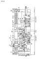
- an X-axis of this glass-plate working apparatus 1 is the left-right direction in the front view, and a Y-axis direction perpendicular to this X-axis is shown in Figs. 2 and 3 .
- the aforementioned cutting section 2 includes a cutting head 9 having a cutter wheel as well as a cutting table 12 on which the glass plate 5 is placed and which supports the glass plate 5 horizontally.
- the grinding work section 3 includes a grinding head 10 having a grinding wheel 58 as well as a grinding table 13 on which the glass plate 5 is placed and which sucks and fixes the glass plate 5 horizontally.
- the cutting head 9 and the grinding head 10 integrally undergo X-axis movement.
- the cutting table 12 and the grinding table 13 undergo Y-axis movement under synchronous control.
- the glass-plate transporting device 6 is provided in such a manner as to extend across above the feed table 7, above the cutting table 12 of the cutting section 2, above a belt conveyor 70 of the bend-breaking section 4, above the grinding table 13 of the grinding work section 3, and above the discharge conveyor 8. Further, this glass-plate transporting device 6 is disposed in parallel to the aforementioned X-axis, and linearly transports the glass plate 5 in parallel to the X-axis.
- a laser measuring instrument 95 is disposed in the grinding work section 3.
- This laser measuring instrument 95 is installed so as to be able to measure the position of one side 97 in a transporting direction 96 (X-axis direction) of the cut glass plate 5 which has been transported from the cutting section 2 to the bend-breaking section 4 and from the bend-breaking section 4 to the grinding work section 3 and is placed on and fixed under suction onto the grinding table 13, and so as to be able to measure by a laser beam the position of one side in the transporting direction 96 (X-axis direction) of the ground glass plate 5 whose cut end face has been ground in this grinding work section 3 and which is sucked and fixed onto the aforementioned grinding work section 13.
- the laser measuring instrument 95 is constituted by a light projecting head 98 for projecting laser light, a light receiving head 99 for receiving light, and a controller.
- the light projecting head 98 and the light receiving head 99 are disposed in face-to-face relation to each other in such a manner as to be located on both sides of the one side 97 in the transporting direction 96 of the glass plate 5 in the vertical direction.
- the position of the one side 97 in the transporting direction 96 of the glass plate 5 is measured by laser light 105. Namely, the position of the edge of the one side 97 which is a rear end side is measured in the transporting direction (or the X-axis direction).
- the light projecting head 98 and the light receiving head 99 are respectively mounted on an upper arm 101 and a lower arm 102 which are provided projectingly on an X-direction position adjusting base 100 via a bracket 103 in such a manner as to be located on both sides of the glass plate 5 in the vertical direction, and the light projecting head 98 and the light receiving head 99 are thus mounted in such a manner as to oppose each other in the vertical direction.
- the X-direction position adjusting base 100 moves and adjusts in the X-axis direction 96 the positions of the aforementioned light projecting head 98 and the light receiving head 99 in conformity with the size of the glass plate 5.
- This X-direction position adjusting base 100 is supported by a machine base 14 via a bracket base 104.
- the cutting head 9 of the cutting section 2 and the grinding head 10 of the grinding work section 3 are mounted on a common moving base 11, and this moving base 11 undergoes linear movement in the X-axis direction (in the left-right direction as viewed from the front side, as indicated by arrows in Fig. 1 ). Accordingly, the cutting head 9 and, hence, a cutter wheel 46, as well as the grinding head 10 and, hence, the grinding wheel 58, use the X-axis in common and undergo integral movement in the X-axis direction.
- a mount 16 is installed forwardly and upwardly of the cutting table 12 and the grinding table 13 along the X-axis direction.
- the mount 16 is installed on a pair of gate-shaped frames 15 erected at front and rear ends of the machine base 14. Two sets of slide rail devices 17 are provided in parallel on a front face 32 of this mount 16 along the X-axis direction.
- Each of these slide rail devices 17 consists of a rail body 18 installed on the mount 16 and a plurality of slides 19 which move on this rail body 18, and the aforementioned common moving base 11 is fixed to these slides 19.
- the aforementioned cutting head 9 and grinding head 10 are mounted on this common moving base 11, as described above.
- the driving of the moving base 11 in the X-axis direction is effected by a feed screw 20 provided between the two sets of slide rail devices 17 and by an X-axis control motor 21 connected to this feed screw 20.
- the aforementioned cutting table 12 is mounted on a pair of slide devices 23 of machine base 14 which are arranged along the Y-axis direction.
- Each of these slide devices 23 has a guide rail 24 and slide blocks assembled to this guide rail 24, and the aforementioned cutting table 12 is fixed to these slide blocks.
- the movement in the Y-axis direction of the cutting table 12 is effected by a feed screw 25 provided along the guide rails 24 and by a Y-axis control motor 26 connected to the feed screw 25.
- the grinding table 13 consists of a plurality of suction cups 22 for sucking and fixing the glass plate 5 on their upper surfaces by setting it horizontally, as well as a main base 31 for holding these suction cups 22.
- the main base 31 of this grinding table 13 is mounted on slide blocks 35 of a pair of slide devices 27 which are arranged along the Y-axis direction.
- slide blocks 35 are respectively assembled to two guide rails 28 which are laid along the Y-axis direction.
- the movement in the Y-axis direction of the grinding table 13 is effected by a feed screw 29 disposed along the guide rails 28 and by a Y-axis control motor 30 connected to this feed screw 29.
- the Y-axis control motor 26 and the Y-axis control motor 30 which are respectively disposed independently are synchronously controlled by the CNC device so that the cutting table 12 of the cutting section 2 and the grinding table 13 of the grinding work section 3 are synchronously moved in the Y-axis direction.
- a bearing unit 33 is mounted in correspondence with the aforementioned cutting table 12, and a bearing unit 34 is mounted in correspondence with the grinding table 13.
- the bearing unit 33 has a rotating shaft 36 which is held by a pair of bearings (not shown).
- the bearing unit 34 has a rotating shaft 38 which is held by a pair of bearings (not shown).
- the aforementioned rotating shafts 36 and 38 are assembled such that their rotational axes are in a state of being perpendicular to the X-Y plane coordinate system, i.e., the upper surface of the glass plate 5, so that the rotating shafts 36 and 38 undergo angle-controlled rotation perpendicularly to the upper surface of the glass plate 5.
- the cutting head 9 is mounted at a lower end portion of the rotating shaft 36 in the cutting section 2 by means of a bracket 39.
- an angle control motor 40 is coupled to an upper end portion of this rotating shaft 36 by means of two spur gears 41.
- the grinding head 10 is mounted at the lower end portion of the rotating shaft 38 by means of a bracket 42.
- an angle control motor 43 is coupled to an upper end portion of this rotating shaft 38 by means of two spur gears 44.
- angle control motors 40 and 43 are respectively held by brackets 45 erected from the front face 32 of the moving base 11, and naturally move in the X-axis direction integrally with the moving base 11.
- the respective rotating shafts 36 and 38 cause the cutting head 9 and the grinding head 10 mounted at their respective end portions to undergo angle-controlled rotation about the axis perpendicular to the upper surface of the glass plate 5 by being subjected to the driving of angle-controlled rotation by the angle control motors 40 and 43.
- the angle control motor 40 and the angle control motor 43 are driven under synchronous control to synchronously effect angle-controlled rotation of the cutting head 9 and the grinding head 10.
- the cutting head 9 includes a cutter head body 47 having the cutter wheel 46, as well as an X-direction slide unit 48 and a Y-direction slide unit 49 for holding this cutter head body 47 and adjusting the position of this cutter head body 47 in two orthogonal directions (X-direction and Y-direction) within a plane parallel to the surface of the glass plate 5.
- the X-direction slide unit 48 consists of an X-slide base 50 and an X-slide 51 assembled to this X-slide base 50, and is fixedly mounted at its X-slide base 50 to the aforementioned rotating shaft 36 by means of the bracket 39.
- the Y-direction slide unit 49 consists of a Y-slide base 53, a Y-slide 54 assembled to the Y-slide base 53 slidingly movably in the Y-axis direction, and a feed screw 55 which is incorporated in the Y-slide base 53 to move the Y-slide 54.
- This Y-direction slide unit 49 is fixed and held at its Y-slide base 53 onto the X-slide 51 of the aforementioned X-slide unit 48. Further, the cutter head body 47 is mounted on the Y-slide 54 of the Y-direction slide unit 49.
- the position of the cutter wheel 46 can be adjusted by adjustment of the feed screw of this Y-direction slide unit 49, so that the moving path of the cutter wheel 46 can be adjusted.
- an air cylinder unit 56 which moves the cutter wheel 46 in the vertical direction to impart cutting pressure to the cutter wheel 46 at the time of forming a cut line on the glass plate 5, is provided at an upper portion of the cutter head body 47.
- the cutting head 10 includes a spindle motor 59 having the grinding wheel 58, as well as an X-direction slide unit 60 and a Y-direction slide unit 61 for finely adjusting the movement of this spindle motor 59 and, hence, the grinding wheel 58 in the X-axis direction and the Y-axis direction in parallel to the upper surface of the glass plate 5.
- the aforementioned X-direction slide unit 60 consists of an X-slide base 62 and an X-slide 63 assembled to this X-slide base 62 slidingly movably in the X-direction (by a feed screw).
- This X-direction slide unit 60 is fixedly mounted on a lower portion of the aforementioned rotating shaft 38 by means of the bracket 42 on the X-slide base 62.
- the Y-direction slide unit 61 consists of a Y-slide base 65, a Y-slide 66 assembled to this Y-slide base 65 slidingly movably in the Y-axis direction, a feed screw 67 incorporated in the Y-slide base 65 to move the Y-slide 66, and a cutting motor 68 mounted on the Y-slide base 65 and coupled to the feed screw 67.
- This Y-direction slide unit 61 is mounted and held at its Y-slide base 65 onto the X-slide 63 of the aforementioned X-direction slide unit 60. Further, the aforementioned spindle motor 59 is mounted on the Y-slide 66 of this Y-direction slide unit 61. Accordingly, the spindle motor 59 and, hence, the grinding wheel 58 is made to effect an automatic cutting operation by the Y-direction slide unit 61, i.e., by the cutting motor 68.
- the cutting motor 68 is driven under control by command numerical values from the CNC device, as will be described later.
- the setting of the cutting depth of the grinding wheel 58 with respect to the cut glass plate 5 is effected by a command numerical value from a numerical control means through this cutting motor 68.
- the moving device for the grinding action surface of the grinding wheel 58 is corrected.
- the cutter wheel 46 of the cutting head 9 and the grinding wheel of the grinding head 10 move while depicting an identical moving path simultaneously in parallel.
- the angle control motor 40 provided for the cutting head 9 and the angle control motor 43 provided for the grinding head 10 are synchronously operated so that control of an identical rotational angle is effected for the cutting head 9 and the grinding head 10 synchronously in parallel.
- the cutting head 9 moves while adjusting the orientation of the cutter wheel 46 to the cutting line whose direction changes from moment to moment, whereas the grinding head 10 moves while undergoing oscillation so that its pressing direction is constantly oriented in a direction normal to a side end face of the glass plate 5.
- the cutting section 2 and the grinding work section 3 undergo depiction of an identical contour moving path and identical-angle controlled movement simultaneously in parallel, and concurrently perform the formation of a cut line (cutting) on the glass plate 5 and peripheral edge grinding of the glass plate 5.
- the bend-breaking section 4 includes the horizontal belt conveyor 70 on which is placed the transported glass plate 5 with the cut line formed thereon, as well as two bend-breaking devices 71 for bend-breaking the glass plate 5 placed on this belt conveyor 70.
- Each of the bend-breaking devices 71 consists of an end cutter unit 72, a press unit 73, and a moving means 74 for moving the end cutter unit 72 and the press unit 73 over the glass plate 5 along the surface of the glass plate 5 while holding the end cutter unit 72 and the press unit 73.
- the moving means 74 includes a Y-direction moving unit 75 for moving under numerical control the end cutter unit 72 and the press unit 73 in the Y-direction while holding the end cutter unit 72 and the press unit 73, as well as an X-direction moving unit 76 for moving under numerical control this Y-direction moving unit 75 in the X-direction.
- This X-direction moving unit 76 is mounted on the mount 16 and a mount 77 by means of brackets.
- the belt conveyor 70 includes a supporting plate/frame 78 for supporting a conveyor belt from inside in the form of a flat surface, and a drive unit 79 for causing the belt conveyor 70 to rotate , and is supported by the machine base 14 by means of brackets in the supporting plate/frame 78.
- the glass plate 5 with the cut line formed thereon in the cutting section 2 is placed on the belt conveyor 70 by a suction pad 86 of a suction pad lifting device 83 corresponding to the cutting section 2. Then, this suction pad lifting device 83 returns to the cutting section 2, and a suction pad 86 of a suction pad lifting device 83 corresponding to the bend-breaking section 4, which returned to this bend-breaking section 4, is alternatively lowered and presses the glass plate 5 placed on the belt conveyor 70, to thereby set the glass plate 5 in a fixed state.
- the end cutter unit 72 of the bend-breaking device 71 is consecutively moved to necessary positions to cut end cutting lines on the glass plate 5.
- the press unit 73 is consecutively moved to necessary positions to effect pressing, thereby bend-breaking and separating unrequired portions.
- the glass plate 5 whose unrequired portions have been bend-broken and separated is sucked and lifted up by the suction pad 86 of a suction pad lifting device 84 corresponding to the bend-breaking section 4, and in this state awaits its conveyance to the ensuing grinding section 3.
- the belt conveyor 70 is operated to discharge bend-broken cullet to the outside.
- the glass-plate transporting section 6 is provided linearly and in parallel to the aforementioned X-axis across above the feed table 7, above the cutting table 12 of the cutting section 2, above the belt conveyor 70 of the bend-breaking section 4, above the grinding table 13 of the grinding work section 3, and above the discharge conveyor 8.
- This glass-plate transporting section 6 has a reciprocally moving base 80 which is NC controlled and effects reciprocating movement in parallel with the X-axis.
- This reciprocally moving base 80 undergoes the aforementioned linear reciprocating movement parallel to the X-axis across above feed table 7, above the cutting table 12, above the belt conveyor 70 of the bend-breaking section 4, above the grinding table 13, and above the discharge conveyor 8.
- the reciprocally moving base 80 is mounted on the mount 77 by means of a below-described slide device 90, and undergoes the above-described linear reciprocating movement.
- four suction pad lifting devices 82, 83, 84, and 85 are linearly arranged on this reciprocally moving base 80 at equal intervals.
- the suction pad lifting devices 82, 83, 84, and 85 respectively correspond to the feed table 7, the cutting table 12 of the cutting section 2, the belt conveyor 70 of the bend-breaking section 4, the grinding table 13 of the grinding work section 3, and the discharge conveyor 8.
- interval distances between adjacent ones of the aforementioned suction pad lifting devices 82, 83, 84, and 85 are naturally identical to interval distances between adjacent ones of the cutting table 12 of the cutting section 2, the belt conveyor 70 of the bend-breaking section 4, and the grinding table 13 of the grinding work section 3.
- Each of the suction pad lifting devices 82, 83, 84, and 85 has the suction pad 86 for sucking at its lower end the glass plate and releasing suction and a lifting unit 87 for raising or lowering this suction pad 86 in the vertical direction, and is at the lifting unit 87 mounted on the aforementioned reciprocally moving base 80 by means of a bracket 81.
- the slide device 90 by means of which the reciprocally moving base 80 is mounted on the mount 77, consists of a pair of guide rails 91 laid in parallel and a slide 92 assembled to these guide rails 91, and the aforementioned reciprocally moving base 80 is mounted on this slide 92.
- the reciprocating movement of the reciprocally moving base 80 is driven under NC control by a feed screw 93 provided between the pair of guide rails 91 and by a control motor 94 coupled to this feed screw 93.
- the aforementioned mount 77 is installed on the pair of frames 15 erected at front and rear ends of the machine base 14, in such a manner as to be located in the rear of the aforementioned mount 16 in parallel therewith.
- the respective suction pad lifting devices 82, 83, 84, and 85 lift up and hold the glass plates 5 at the time of forward movement of the reciprocally moving base 80, all together undergo reciprocating movement, and return to their backward movement ends in an empty state at the time of backward movement.
- the glass plates 5 are transported each aforementioned interval distance on each occasion of the forward movement when the reciprocally moving base 80 repeatedly undergoes NC-controlled reciprocating movement. Further, in particular, the glass plates 5 are transported linearly across the cutting table 12, the belt conveyor 70, and the grinding table 13.
- the direction of reciprocating movement of the aforementioned reciprocally moving base 80 is the aforementioned transporting direction of the glass plates 5 and is also the X-axis direction.
- the cutting head 9 and the cutting table 12 of the cutting section 2, the bend-breaking devices 71 of the bend-breaking section 4, and the grinding head 10 and the grinding table 13 of the grinding work section 3 are all on standby at starting positions. Then, the reciprocally moving base 80 of the glass-plate transporting device 6 is located at its backward movement end.
- the position at this time is the position for receiving the glass plate 5. Further, the suction pad lifting device 82 of the glass-plate transporting device 6 is positioned immediately above the feed table 7, the suction pad lifting device 83 is positioned immediately above the glass plate supporting base of the cutting section 2, the glass plate lifting device 84 is positioned immediately above the belt conveyor 70, and the suction pad lifting device 85 is positioned immediately above the glass plate supporting base of the grinding work section 3.
- the respective suction pad lifting devices 82, 83, 84, and 85 concurrently lower the suction pads 86 to suck and lift up the glass plates 5, whereupon the reciprocally moving base 80 starts forward movement simultaneously.
- the respective suction pad lifting devices 82, 83, 84, and 85 have their suction pads 86 sucking the glass plates 5, and integrally move forward to effect the transporting movement of the glass plates.
- the aforementioned suction pad lifting device 82 When the reciprocally moving base 80 reaches a forward movement end, the aforementioned suction pad lifting device 82 is positioned immediately above the cutting table 12 of the cutting section 2, the suction pad lifting device 83 is positioned immediately above the belt conveyor 70 of the bend-breaking section 4, the glass plate lifting device 84 is positioned immediately above the grinding table 13 of the grinding work section 3, and the suction pad lifting device 85 is positioned immediately above the discharge conveyor. Then, the respective suction pad lifting devices 82, 83, 84, and 85 concurrently lower the suction pads 86 for sucking the glass plates and release the suction to thereby deliver the glass plates 5, respectively. Thereupon, the suction pad lifting devices 82, 83, 84, and 85 lift up the emptied suction pads 86. Then, the aforementioned reciprocally moving base 80 starts backward movement integrally with the emptied suction pads 86, and returns to the backward movement end.
- the glass-plate transporting device 6 Upon the start of operation of this glass-plate working apparatus 1, the glass-plate transporting device 6 is operated. Namely, the suction pad 86 is lowered over the feed table 7, and sucks and lifts up the unshaped glass 5 on the feed table 7, whereupon the reciprocally moving base 80 is moved forward (under numerical control). When the suction pad 86 with this unshaped glass plate 5 sucked thereby reaches the cutting table 12 of the cutting section, the suction pad 86 is lowered and releases suction, and places the unshaped glass plate 5 on the cutting table 12. Then, the emptied suction pad 86 is raised, the reciprocally moving base 80 returns backward, and the empty suction pad 86 returns to over the feed table 7.
- the suction pad 86 corresponding to this cutting section 2 returns to this cutting section 2.
- the cutting head 9 and the cutting table 12 with the unshaped glass plate placed thereon are moved under NC control, and the cutter wheel forms a cut line on the unshaped glass plate.
- the cutting table 12 Upon completion of the formation of this cut line, the cutting table 12 returns to the starting point.
- the suction pad 86 which returned is lowered, sucks and lifts up the unshaped glass plate 5 with this cut line formed thereon, and is transported toward the bend-breaking section 4 in the forward movement of the reciprocally moving base 80 (under NC control).
- the suction pad 86 Upon reaching the bend-breaking section 4, the suction pad 86 is lowered, releases suction, and places the glass plate 5 with the cut line formed thereon onto the belt conveyor 70. Then, this suction pad 86 returns toward the cutting section 2. In turn, the suction pad 86 corresponding to this bend-breaking section 4 returns to this bend-breaking section 4, is immediately lowered, sucks the glass plate 5 with the cut line formed thereon, which is placed on the belt conveyor 70, and presses the same against the belt conveyor 70 so that it will not move.
- the bend-breaking section 4 operates in this state. Namely, by the operation of the two bend-breaking devices 71, the end cutter unit 72 and the press unit 73 move over that glass plate 5 with the cut line formed thereon to effect end cutting at a necessary position and then effect snapping along the cut line by a pressing operation, to thereby obtain a cut glass plate 5.
- the suction pad 86 which is continuing suction is raised as it is, and lifts up the cut glass plate 5. Then, the suction pad 86 waits for a forward movement start while sucking and lifting the cut glass plate 5.
- the formation of a cut line on an ensuing glass plate and the grinding of a preceding glass plate 5 are being carried out under NC control.
- the formation of a cut line and the grinding work in the cutting section 2 and the grinding work section 3 are then finished, and the glass-plate transporting device is operated to forwardly move the reciprocally moving base 80 (under NC control).
- the suction pad 86 which was on standby in the bend-breaking section 4 while sucking and lifting the cut glass plate 5 is then moved forward to the ensuing grinding work section 3.
- the suction pad 86 Upon reaching a position immediately above the grinding table 13 of the grinding work section 3, the suction pad 86 is lowered, releases suction, and places the cut glass plate 5 on the grinding table 13. Then, the suction pad 86 which has been emptied and corresponds to the bend-breaking section 4 is raised, and returns to the bend-breaking section 4 by the backward movement of the reciprocally moving base 80.
- the glass plate 5 is sequentially sent from the feeding section 7 to the cutting section 2, the bend-breaking section 4, the grinding work section 3, and the discharge conveyor 8 while being positionally changed from one to another.
- the respective processing is simultaneously carried out in the cutting section 2, the bend-breaking section 4, and the grinding work section 3, and the glass plates 5 whose peripheries have been ground are finally discharged consecutively.
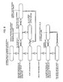
- the automatic measurement and correction of processing dimensions is implemented through the following steps.
- Step 1 in which this glass-plate working apparatus 1 is operated, and the cut glass plate 5 is transported to and placed on the grinding table 13 of the grinding work section 3 from the cutting section 2 via the bend-breaking section 4;
- Step 2 in which the position of one side 97 in the transporting direction of the cut glass plate 5 is measured by the laser measuring instrument 95 installed in the grinding work section 3 to obtain a measured value;
- Step 3 in which a comparison is made between the measured value obtained by the laser measuring instrument 95 and a preset value set in the CNC device, and when they differ, an error value thereof is calculated;
- Step 4 in which, on the basis of a thermal displacement amount value of the glass-plate transporting device 6 set in the CNC device, a determination is made as to whether the aforementioned error value is due to the thermal displacement of the glass-plate transporting device 6 or due to a cutting error in the cutting section 2;
- Step 5 in which in a case where a value
- Step 1 in which this glass-plate working apparatus 1 is operated, and the cut glass plate 5 is transported to and placed on the grinding table 13 of the grinding work section 3 from the cutting section 2 via the bend-breaking section 4;
- Step 2 in which the position of one side 97 in the transporting direction of the cut glass plate 5 is measured by the laser measuring instrument 95 installed in the grinding work section 3 to obtain a measured value;
- Step 3 in which the above-described glass-plate working apparatus 1 is operated to effect the grinding work of the aforementioned cut glass plate 5, and upon completion of the grinding work the position of the one side 97 in the transporting direction 96 of this ground glass plate 5 is measured again by the laser measuring instrument 95 to obtain a measured value;
- Step 4 in which a comparison is made between the aforementioned measured value after the completion of the grinding work and a grinding target value obtained by incorporating a preset cutting depth value of the grinding wheel 58 into the
Abstract
A glass-plate working apparatus 1 includes a cutting section 2 for forming a cut line on an unshaped glass plate 5, a bend-breaking section 4 for effecting bend-breaking along the cut line to obtain a cut glass plate 5 of a required shape, a grinding work section 3 for grinding a cut end face of the cut glass plate 5, and a glass-plate transporting device 6 for transporting the glass plate 5, and a laser measuring instrument 95 is disposed in the grinding work section 3.
Description
- The present invention relates to a method of automatically measuring and correcting processing dimensions in a glass-plate working apparatus for manufacturing such as glass plates for window glass of automobiles, glass plates for liquid crystal displays, and glass plates for furniture from unshaped plate glass by subjecting it to cutting and grinding work, as well as a glass-plate working apparatus equipped with an automatic measuring device.
- The present invention concerns a method in which, in a glass-plate working apparatus equipped with a cutting section, a grinding work section, and a glass-plate transporting device and adapted to transport a cut glass plate from the cutting section to the grinding work section by the glass-plate transporting device and effect the grinding work of cut end faces in this grinding work section, the position of the cut glass plate transported and processing dimensions of cutting and grinding work are automatically measured, and are automatically corrected on the basis of the measured values.
- Further, the present invention relates to a method of automatically measuring and correcting processing dimensions in a glass-plate working apparatus with the aforementioned cutting section, grinding work section, and glass-plate transporting device operated by being NC controlled by a computer numerical controller, as well as a glass-plate working apparatus equipped with an automatic measuring device. It should be noted that the aforementioned computer numerical controller will be hereinafter referred to as the CNC device.
- Furthermore, the present invention concerns a method in which, in a glass-plate working apparatus equipped with a cutting section, a grinding work section, and a glass-plate transporting device and adapted to cut (form cut lines in and bend-break) a glass plate in the cutting section by NC controlling a cutting head having a cutter wheel or the cutting head and a glass-plate supporting base with the glass plate placed thereon, transport the cut glass plate under NC control from the glass-plate supporting base of this cutting section to a glass-plate supporting base of the grinding work section by the glass-plate transporting device, and effect the grinding work of end faces of the cut glass plate in this grinding work section by NC controlling both a grinding head having a grinding wheel and the glass-plate supporting base with the cut glass plate placed and fixed thereon, the position, cutting work dimensions, and grinding work dimensions of the cut glass plate transported are automatically measured, and the processing dimensions are automatically corrected on the basis of the measured values.
- Still further, the present invention concerns a method in which, in a glass-plate working apparatus equipped with a cutting section, a bend-breaking section, a grinding work section, and a glass-plate transporting device and adapted to form cut lines in a glass plate in the cutting section by NC controlling a cutting head having a cutter wheel or the cutting head and a glass-plate supporting base with the glass plate held thereon, transport under NC control this glass plate with the cut lines formed thereon from the glass-plate supporting base of the cutting section to the bend-breaking section by the aforementioned glass-plate transporting device, bend-break the glass plate along the aforementioned cut lines in this bend-breaking section to obtain a cut glass plate, transport this cut glass plate from this bend-breaking section to a glass-plate supporting base of the grinding work section by the aforementioned glass-plate transporting means under numerical control, and effect the grinding work of end faces of the cut glass plate in this grinding work section by NC controlling both a grinding head having a grinding wheel and the glass-plate supporting base with the cut glass plate placed and fixed thereon, the position, cutting work dimensions, and grinding work dimensions of the cut glass plate transported are automatically measured, and the processing dimensions are automatically corrected on the basis of the measured values.
- It should be noted that, hereinafter, the glass-plate supporting base of the aforementioned cutting section will be referred to as a cutting table, and the glass-plate supporting base of the grinding work section will be referred to as a grinding table.
- Conventionally, a glass-plate working apparatus described in International Publication No.
WO2004/039538 is known as a glass-plate working method and a glass-plate working apparatus in which a cut glass plate which has been transported from the cutting section to the grinding work section through the bend-breaking section is subjected to grinding work in this grinding work section, the processing dimensions of the glass plate thus subjected to grinding work are automatically measured, and the cutting depth of the grinding wheel is automatically corrected on the basis of this measured value. This glass-plate working apparatus includes a cut-line forming means for forming a cut line on the glass plate; a bend-breaking means for bend-breaking along the cut line the glass plate with the cut line formed thereon by the cut-line forming means; a grinding means having a disk-shaped grinding wheel for grinding peripheral edges of the glass plate bend-broken by the bend-breaking means by coming into contact with the peripheral edges; a detecting means for detecting the position of the peripheral edge of the glass plate ground by the grinding means; a setting means for setting a set value (reference value) indicating a desired position of the peripheral edge of the glass plate ground by the grinding means; a correcting means for correcting the position of the grinding wheel with respect to the arriving glass plate on the basis of a detected value indicating the position of the peripheral edge of the glass plate detected by the detecting means and a set value set in advance by the setting means; and a transporting means for transporting the glass plate sequentially to the cut-line forming means, the bend-breaking means, and the grinding means. - In short, this is a method in which the amount of wear of the grinding wheel is measured by detecting the position of the peripheral edge of the ground glass plate, and the position of the grinding wheel is corrected on the basis of this measured amount of wear.
- Additionally, this is a method in which, in the correcting step, a deviation value between a detected value indicating the position of the peripheral edge of the ground glass plate and a preset value is determined, and the position of the grinding wheel is corrected on the basis of the determined deviation value.
- However, with the above-cited glass-plate working apparatus described in
WO2004/039538 , despite the fact that the glass plate is transported from the cutting section to the grinding work section through the bend-breaking section by the transporting means, the position of the cut glass plate transported is not detected. For this reason, there is a possibility that the position of the cut glass plate placed in the grinding work section may be misaligned from the set proper position. - In addition, it is also unclear whether the cut glass plate has been cut to set proper processing dimensions. Even if, in the grinding work section, grinding work is effected in the above-described state, and the position of peripheral edge of the ground glass plate is detected, followed by the correction of the position of the grinding wheel on the basis of the detected value, grinding dimensions are corrected quite incompletely only with this correction of the position of the grinding wheel. Owing to the thermal displacement of the transporting means which is repeatedly operated, the position of the cut glass plate placed becomes gradually misaligned from the set position, and therefore faulty grinding occurs.
- In addition, in cases where the cut glass plate transported to the grinding work section has not been cut to the set proper processing dimensions, the set position of the grinding wheel with respect to the cut glass plate becomes inaccurate, the grinding becomes incorrect owing to the escape of the grinding wheel due to excessive contact, and the processing dimensions fail to be constant.
- Accordingly, the present invention has been devised in view of the above-described drawbacks of the conventional glass-plate working apparatus, and its object is to provide a method of automatically measuring and correcting processing dimensions of a glass plate and a glass-plate working apparatus, which make it possible to effect automatic measurement and correction of processing dimensions of a cut glass plate and a ground glass plate in processing production and effect automatic measurement and correction of the transported position of the glass plate which is transported from the cutting section to the grinding work section.
- In accordance with the present invention, there is provided a method of automatically correcting a grinding dimension of a glass plate, comprising the steps of: measuring a position of one side in a transporting direction of a cut glass plate which has been transported from a cutting section to a grinding work section by a glass-plate transporting device; making a comparison between a measured value thereof and a preset value set in a CNC device for numerically controlling the transporting operation of the glass-plate transporting device; and in a case where a difference between the measured value and the preset value is due to the thermal displacement of the glass-plate transporting device, correcting the preset value on the basis of the difference, and in a case where the difference is due to a cutting error, setting the difference as an offset value in the CNC device.
- In addition, in accordance with the present invention, there is provided a method of automatically correcting a processing dimension in a glass-plate working apparatus in which a glass plate is cut in a cutting section by NC controlling by a CNC device a cutting head having a cutter wheel or the cutting head and a cutting table holding the glass plate, the cut glass plate is transported from the cutting table of the cutting section to a grinding table of a grinding work section by a glass-plate transporting device, and an end face of the cut glass plate is subjected to grinding work in the grinding work section by NC controlling by the CNC device the grinding table and the grinding head having the grinding wheel, comprising the steps of: installing in the grinding work section a laser measuring instrument for measuring by laser light a position of one side in a transporting direction of the cut glass plate placed on the grinding table; and implementing the following first to fifth steps: a first step in which the glass-plate working apparatus is operated, and the cut glass plate is transported to and placed on the grinding table of the grinding work section from the cutting section; a second step in which the position of the one side in the transporting direction of the cut glass plate is measured by the laser measuring instrument; a third step in which a comparison is made between a measured value obtained by the laser measuring instrument and a preset value set in the CNC device, and when they differ, an error value thereof is calculated; a fourth step in which, on the basis of a thermal displacement amount value of the glass-plate transporting device set in the CNC device, a determination is made as to whether the error value is due to the thermal displacement of the glass-plate transporting device or due to a cutting error in the cutting section; and a fifth step in which in a case where the error value is due to the thermal displacement of the glass-plate transporting device, and the thermal displacement amount value in the CNC device is corrected and set on the basis of the error value, or in a case where the error value is due to a cutting error, the error value is set as an offset value in the CNC device.
- In addition, in accordance with the present invention, there is provided a method of automatically correcting a processing dimension in the above-described glass-plate working apparatus, comprising the steps of: installing in the grinding work section a laser measuring instrument for measuring by laser light a position of one side in a transporting direction of the cut glass plate placed on the grinding table; and implementing the following first to fifth steps: a first step in which the glass-plate working apparatus is operated, and the cut glass plate is transported to and placed on the grinding table of the grinding work section from the cutting section; a second step in which the position of the one side in the transporting direction of the cut glass plate is measured by the laser measuring instrument; a third step in which the glass-plate working apparatus is operated to effect the grinding work of the cut glass plate, and upon completion of the grinding work the position of the one side in the transporting direction of that ground glass plate is measured again by the laser measuring instrument to obtain a measured value; a fourth step in which a comparison is made between the measured value after the completion of the grinding work and a grinding target value obtained by incorporating a preset cutting depth value of the grinding wheel into the measured value prior to the grinding work, to determine the presence or absence of the escape of the grinding wheel due to a grinding load; and a fifth step in which in a case where the measured value after the grinding work is greater than the grinding target value, the preset cutting depth value of the grinding wheel is corrected and set on the basis of an error value thereof.
- In addition, in accordance with the present invention, there is provided a method of automatically correcting a processing method in the above-described glass-plate working apparatus, comprising the steps of: installing in the grinding work section a laser measuring instrument for measuring by laser light a position of one side in a transporting direction of the glass plate placed on the grinding table; and implementing the following first to fifth steps: a first step in which the glass-plate working apparatus is operated, and the cut glass plate is transported to and placed on the grinding table of the grinding work section from the cutting section; a second step in which the position of the one side in the transporting direction of the cut glass plate is measured by the laser measuring instrument; a third step in which a comparison is made between a measured value obtained by the laser measuring instrument and a preset value set in the CNC device, and when they differ, an error value thereof is calculated; a fourth step in which, on the basis of a thermal displacement amount value of the glass-plate transporting device set in the CNC device, a determination is made as to whether the error value is due to the thermal displacement of the glass-plate transporting device or due to a cutting error in the cutting section; and a fifth step in which in a case where a value other than 0 has been set as the thermal displacement amount value, the error value is assumed to be due to the thermal displacement of the glass-plate transporting device, and the thermal displacement amount value set in the CNC device is corrected on the basis of the error value, or in a case where a value of 0 has been set as the thermal displacement amount value or the thermal displacement amount value is blank, the error value is assumed to be due to a cutting error, and the error value is set as an offset value in the CNC device which controls the cutting section.
- In addition, in accordance with the present invention, there is provided a method of automatically correcting a processing dimension in the above-described glass-plate working apparatus, comprising the steps of: installing in the grinding work section a laser measuring instrument for measuring by laser light a position of one side in a transporting direction of the glass plate placed on the grinding table; and implementing the following first to ninth steps: a first step in which the glass-plate working apparatus is operated, and the cut glass plate is transported to and placed on the grinding table of the grinding work section from the cutting section; a second step in which the position of the one side in the transporting direction of the cut glass plate is measured by the laser measuring instrument; a third step in which a comparison is made between a measured value obtained by the laser measuring instrument and a preset value set in the CNC device, and when they differ, an error value thereof is calculated; a fourth step in which, on the basis of a thermal displacement amount value of the glass-plate transporting device set in the CNC device, a determination is made as to whether the error value is due to the thermal displacement of the glass-plate transporting device or due to a cutting error in the cutting section; a fifth step in which in a case where the error value is due to the thermal displacement of the glass-plate transporting device, and the thermal displacement amount value in the CNC device is corrected and set on the basis of the error value, or in a case where the error value is due to a cutting error, the error value is set as an offset value in the CNC device which NC controls the cutting section; a sixth step in which the glass-plate working apparatus subjected to automatic correction through the above-described steps 1 to 5 is operated, the cut glass plate is transported to and placed on the grinding table of the grinding work section from the cutting section, and the position of the one side in the transporting direction of the cut glass plate is measured again by the laser measuring instrument; a seventh step in which the glass-plate working apparatus is further operated to effect the grinding work of the cut glass plate, and upon completion of the grinding work the position of the one side in the transporting direction of that ground glass plate is measured again by the laser measuring instrument; an eighth step in which a comparison is made between the measured value after the completion of the grinding work and a grinding target value obtained by incorporating a preset cutting depth value of the grinding wheel into the measured value prior to the grinding work, to determine the presence or absence of the escape of the grinding wheel due to a grinding load; and a ninth step in which in a case where the measured value after the grinding work is greater than the grinding target value, the preset cutting depth value of the grinding wheel is corrected and set on the basis of an error value thereof.
- Further, in accordance with the present invention, there is provided a method of automatically correcting a processing method in a glass-plate working apparatus in which a cut line is formed on a glass plate in a cutting section by NC controlling by a CNC device a cutting head having a cutter wheel and a cutting table holding the glass plate, the glass plate with the cut line formed thereon is transported from the cutting table of the cutting section to a bend-breaking section by a glass-plate transporting device under NC control, the glass plate with the cut line formed thereon is bend-broken in the bend-breaking section to obtain a cut glass plate, the cut glass plate is transported from the bend-breaking section to a grinding table of a grinding work section by the glass-plate transporting device under NC control, and an end face of the cut glass plate is subjected to grinding work in the grinding work section by NC controlling by the CNC device the grinding table and the grinding head having the grinding wheel, comprising the steps of: installing in the grinding work section a laser measuring instrument for measuring by laser light a position of one side in a transporting direction of the glass plate placed on the grinding table; and implementing the following first to fifth steps: a first step in which the glass-plate working apparatus is operated, and the cut glass plate is transported to and placed on the grinding table of the grinding work section from the cutting section via the bend-breaking section; a second step in which the position of the one side in the transporting direction of the cut glass plate is measured by the laser measuring instrument; a third step in which a comparison is made between a measured value obtained by the laser measuring instrument and a preset value set in the CNC device, and when they differ, an error value thereof is calculated; a fourth step in which, on the basis of a thermal displacement amount value of the glass-plate transporting device set in the CNC device, a determination is made as to whether the error value is due to the thermal displacement of the glass-plate transporting device or due to a cutting error in the cutting section; and a fifth step in which in a case where the error value is due to the thermal displacement of the glass-plate transporting device, and the thermal displacement amount value in the CNC device is corrected and set on the basis of the error value, or in a case where the error value is due to a cutting error, the error value is set as an offset value in the CNC device which NC controls the cutting section.
- Furthermore, in accordance with the present invention, there is provided a method of automatically correcting a processing dimension in the above-described glass-plate working apparatus, comprising the steps of: installing in the grinding work section a laser measuring instrument for measuring by laser light a position of one side in a transporting direction of the glass plate placed on the grinding table; and implementing the following first to ninth steps: a first step in which the glass-plate working apparatus is operated, and the cut glass plate is transported to and placed on the grinding table of the grinding work section from the cutting section via the bend-breaking section; a second step in which the position of the one side in the transporting direction of the cut glass plate is measured by the laser measuring instrument; a third step in which a comparison is made between a measured value obtained by the laser measuring instrument and a preset value set in the CNC device, and when they differ, an error value thereof is calculated; a fourth step in which, on the basis of a thermal displacement amount value of the glass-plate transporting device set in the CNC device, a determination is made as to whether the error value is due to the thermal displacement of the glass-plate transporting device or due to a cutting error in the cutting section; a fifth step in which in a case where the error value is due to the thermal displacement of the glass-plate transporting device, and the thermal displacement amount value in the CNC device is corrected and set on the basis of the error value, or in a case where the error value is due to a cutting error, the error value is set as an offset value in the CNC device which NC controls the cutting section; a sixth step in which the glass-plate working apparatus subjected to automatic correction through the above-described steps 1 to 5 is operated again, the cut glass plate is transported to and placed on the grinding table of the grinding work section from the cutting section via the bend-breaking section, and the position of the one side in the transporting direction of that cut glass plate is measured again by the laser measuring instrument to obtain a measured value; a seventh step in which the glass-plate working apparatus is further operated to effect the grinding work of the cut glass plate, and the position of the one side in the transporting direction of that ground glass plate sucked as it is on the grinding table is measured again by the laser measuring instrument to obtain a measured value thereof; an eighth step in which a comparison is made between the measured value after the completion of the grinding work and a grinding target value obtained by incorporating a preset cutting depth value of the grinding wheel into the measured value prior to the grinding work, to determine the presence or absence of the escape of the grinding wheel due to a grinding load; and a ninth step in which in a case where the measured value after the grinding work is greater than the grinding target value, the preset cutting depth value of the grinding wheel is corrected and set on the basis of an error value thereof.
- Still further, in accordance with the present invention, there is provided a glass-plate working apparatus comprising: a cutting section for cutting a glass plate; a grinding work section for effecting grinding work of an end face of the cut glass plate; a glass-plate transporting device for transporting the cut glass plate cut in the cutting section from the cutting section to the grinding work section; a CNC device for NC controlling the operation of cutting the glass plate in the cutting section, the operation of grinding the cut glass plate in the grinding work section, and the transporting operation of the glass-plate transporting device, respectively; and a laser measuring instrument for measuring by laser light a position of one side in a transporting direction of the glass plate in the grinding work section, wherein a comparison is made between a measured value based on the laser measuring instrument and a preset value set in the CNC device, and the preset value is corrected or an offset value is set on the basis of a difference between the measured value and the preset value.
- Furthermore, in accordance with the present invention, there is provided a glass-plate working apparatus in which a glass plate is cut in a cutting section by NC controlling by a CNC device a cutting head having a cutter wheel or the cutting head and a cutting table holding the glass plate, the cut glass plate is transported from the cutting table of the cutting section to a grinding table of a grinding work section by a glass-plate transporting device, and an end face of the cut glass plate is subjected to grinding work in the grinding work section by NC controlling by the CNC device the grinding table and the grinding head having the grinding wheel, comprising: a laser measuring instrument installed in the grinding work section so as to be able to measure by laser light a position of one side in a glass plate transporting direction of a cut glass plate or a ground glass plate placed on the grinding table.
- According to the present invention, it is possible to easily determine by automatic measurement whether or not the cut glass plate, which has been first transported from the cutting section and placed on the grinding table of the grinding work section by the glass-plate transporting device, has been processed to as-designed dimensional accuracy or has been placed at an as-designed accurate position. Namely, as described above, the laser measuring instrument is installed in the grinding work section such that the position of one side in the transporting direction of the cut glass plate placed on the grinding table can be measured by laser light, and the position of the one side in the transporting direction of the cut glass plate transported from the cutting section to and placed on the grinding table of the grinding work section is measured by the laser measuring instrument. A comparison is made between this measured value and a preset value, and thus in a case where there is no difference (the measured value is within an allowance), it is determined that the cut glass plate has been processed to an as-designed cutting dimension and placed at an as-designed accurate position on the grinding table. On the other hand, in a case where the measured value and the set value differ, it is possible to easily determine on the basis of a thermal displacement amount value of the glass-plate transporting device set in the CNC device whether that difference is due to the thermal displacement of the glass-plate transporting device or due to a cutting error in the cutting section, for instance, in a case where a thermal displacement amount value of the glass-plate transporting device set in the CNC device is numeric other than zero, zero, or blank.
- In addition, in the case where the difference is due to the thermal displacement of the glass-plate transporting device, the transporting and placing position of the cut glass plate is automatically corrected by correcting and setting the thermal displacement amount value in the CNC device, whereas in the case where the difference is due to a cutting error, the processing dimension of the cut glass plate is automatically corrected by setting that difference as an offset value in the CNC device.
- Thereafter, the cut glass plate with the as-designed accurate processing dimension is placed accurately at an as-designed position on the grinding table of the grinding work section. In addition, it is also possible to easily make automatic measurement as to whether or not the grinding work has continued to be finished to as-designed processing dimensional accuracy, and further automatic correction is made possible. Namely, the presence or absence of the escape of the grinding wheel due to a grinding load can be easily determined by grinding the cut glass plate cut to as-designed cutting dimension and placed at an as-designed accurate position on the grinding table, by measuring again by the aforementioned laser measuring instrument the position of the one side in the transporting direction of that ground glass plate, and by making a comparison between that measured value and a value obtained by incorporating a set cutting depth value of the grinding wheel into the measured value of that cut glass plate. When the escape of the grinding wheel has been determined, the cutting depth of the grinding wheel is corrected on the basis of the aforementioned error value, thereby making it possible to easily effect automatic correction of the processing dimension of the ground glass plate.
- It should be noted that, in the present invention, the glass-plate grinding method in the grinding work section may be a grinding method of polar coordinate control in which the grinding table for placing and fixing the glass plate is rotated under numeral control, while the grinding head and, hence, the grinding wheel are advanced or retracted under numerical control with respect to the grinding table, and the grinding wheel is brought into contact with and made to follow a peripheral edge of the rotating glass plate, to thereby effect grinding work.
- The drawings show a glass-plate working apparatus in accordance with an embodiment of the present invention.
-
Fig. 1 is a front elevational view; -
Fig. 2 is a plan view; -
Fig. 3 is a partially fragmentary plan view; -
Fig. 4 is a cross-sectional view taken along line A - A inFig. 2 ; -
Fig. 5 is a partially fragmentary plan view; -
Fig. 6 is a diagram explaining the operation; -
Fig. 7 is an explanatory diagram of a grinding head shown inFigs. 1 to 6 ; and -
Fig. 8 is a block diagram explaining the automatic measurement and correction of processing dimensions in accordance with the present invention. - Next, a description will be given of an embodiment of the present invention with reference to the drawings.
-
Figs. 1 to 6 show the present glass-plate working apparatus 1 which is NC controlled by a CNC device (computer numeral controller) and effects the glass plate working operation. - As shown in
Figs. 1 to 6 , in this glass-plate working apparatus 1, acutting section 2 for forming a cut line on anunshaped glass plate 5 is disposed on the right side; a bend-breakingsection 4 for effecting bend-breaking along the cut line to obtain acut glass plate 5 of a required shape is disposed next to it; agrinding work section 3 for grinding the cut end face of thecut glass plate 5 is disposed further next to it; and a glass-plate transporting device 6 for transporting theglass plate 5 is disposed in the rear. - It should be noted that the
cutting section 2, the bend-breakingsection 4, and thegrinding work section 3 mentioned above are arranged at equal intervals. - It should be noted that a feed table 7 for the
glass plate 5 is disposed on the right side of thecutting section 2, and adischarge conveyor 8 is disposed on the left side of thegrinding work section 3. - As shown in
Figs. 1 and5 , an X-axis of this glass-plate working apparatus 1 is the left-right direction in the front view, and a Y-axis direction perpendicular to this X-axis is shown inFigs. 2 and3 . Theaforementioned cutting section 2 includes acutting head 9 having a cutter wheel as well as a cutting table 12 on which theglass plate 5 is placed and which supports theglass plate 5 horizontally. Meanwhile, thegrinding work section 3 includes a grindinghead 10 having agrinding wheel 58 as well as a grinding table 13 on which theglass plate 5 is placed and which sucks and fixes theglass plate 5 horizontally. - The
cutting head 9 and the grindinghead 10 integrally undergo X-axis movement. - The cutting table 12 and the grinding table 13 undergo Y-axis movement under synchronous control.
- As shown in
Figs. 2 ,4 ,5 , and6 , the glass-plate transporting device 6 is provided in such a manner as to extend across above the feed table 7, above the cutting table 12 of thecutting section 2, above abelt conveyor 70 of the bend-breakingsection 4, above the grinding table 13 of the grindingwork section 3, and above thedischarge conveyor 8. Further, this glass-plate transporting device 6 is disposed in parallel to the aforementioned X-axis, and linearly transports theglass plate 5 in parallel to the X-axis. - As shown in
Figs. 1 to 6 , in this glass-plate working apparatus 1, alaser measuring instrument 95 is disposed in the grindingwork section 3. - This
laser measuring instrument 95 is installed so as to be able to measure the position of oneside 97 in a transporting direction 96 (X-axis direction) of thecut glass plate 5 which has been transported from thecutting section 2 to the bend-breakingsection 4 and from the bend-breakingsection 4 to the grindingwork section 3 and is placed on and fixed under suction onto the grinding table 13, and so as to be able to measure by a laser beam the position of one side in the transporting direction 96 (X-axis direction) of theground glass plate 5 whose cut end face has been ground in this grindingwork section 3 and which is sucked and fixed onto the aforementioned grindingwork section 13. - The
laser measuring instrument 95 is constituted by alight projecting head 98 for projecting laser light, alight receiving head 99 for receiving light, and a controller. Thelight projecting head 98 and thelight receiving head 99 are disposed in face-to-face relation to each other in such a manner as to be located on both sides of the oneside 97 in the transportingdirection 96 of theglass plate 5 in the vertical direction. - Further, the position of the one
side 97 in the transportingdirection 96 of theglass plate 5 is measured bylaser light 105. Namely, the position of the edge of the oneside 97 which is a rear end side is measured in the transporting direction (or the X-axis direction). - The
light projecting head 98 and thelight receiving head 99 are respectively mounted on anupper arm 101 and alower arm 102 which are provided projectingly on an X-directionposition adjusting base 100 via abracket 103 in such a manner as to be located on both sides of theglass plate 5 in the vertical direction, and thelight projecting head 98 and thelight receiving head 99 are thus mounted in such a manner as to oppose each other in the vertical direction. - The X-direction
position adjusting base 100 moves and adjusts in theX-axis direction 96 the positions of the aforementionedlight projecting head 98 and thelight receiving head 99 in conformity with the size of theglass plate 5. - This X-direction
position adjusting base 100 is supported by amachine base 14 via abracket base 104. The cuttinghead 9 of thecutting section 2 and the grindinghead 10 of the grindingwork section 3 are mounted on a common movingbase 11, and this movingbase 11 undergoes linear movement in the X-axis direction (in the left-right direction as viewed from the front side, as indicated by arrows inFig. 1 ). Accordingly, the cuttinghead 9 and, hence, acutter wheel 46, as well as the grindinghead 10 and, hence, the grindingwheel 58, use the X-axis in common and undergo integral movement in the X-axis direction. - A
mount 16 is installed forwardly and upwardly of the cutting table 12 and the grinding table 13 along the X-axis direction. - The
mount 16 is installed on a pair of gate-shapedframes 15 erected at front and rear ends of themachine base 14. Two sets ofslide rail devices 17 are provided in parallel on afront face 32 of thismount 16 along the X-axis direction. - Each of these
slide rail devices 17 consists of arail body 18 installed on themount 16 and a plurality ofslides 19 which move on thisrail body 18, and the aforementioned common movingbase 11 is fixed to theseslides 19. - The
aforementioned cutting head 9 and grindinghead 10 are mounted on this common movingbase 11, as described above. The driving of the movingbase 11 in the X-axis direction is effected by afeed screw 20 provided between the two sets ofslide rail devices 17 and by anX-axis control motor 21 connected to thisfeed screw 20. - The aforementioned cutting table 12 is mounted on a pair of
slide devices 23 ofmachine base 14 which are arranged along the Y-axis direction. - Each of these
slide devices 23 has aguide rail 24 and slide blocks assembled to thisguide rail 24, and the aforementioned cutting table 12 is fixed to these slide blocks. - The movement in the Y-axis direction of the cutting table 12 is effected by a
feed screw 25 provided along the guide rails 24 and by a Y-axis control motor 26 connected to thefeed screw 25. - Meanwhile, the grinding table 13 consists of a plurality of
suction cups 22 for sucking and fixing theglass plate 5 on their upper surfaces by setting it horizontally, as well as amain base 31 for holding thesesuction cups 22. - Further, the
main base 31 of this grinding table 13 is mounted on slide blocks 35 of a pair ofslide devices 27 which are arranged along the Y-axis direction. - Of course, the slide blocks 35 are respectively assembled to two
guide rails 28 which are laid along the Y-axis direction. - The movement in the Y-axis direction of the grinding table 13 is effected by a
feed screw 29 disposed along the guide rails 28 and by a Y-axis control motor 30 connected to thisfeed screw 29. - The Y-
axis control motor 26 and the Y-axis control motor 30 which are respectively disposed independently are synchronously controlled by the CNC device so that the cutting table 12 of thecutting section 2 and the grinding table 13 of the grindingwork section 3 are synchronously moved in the Y-axis direction. - Next, as shown in
Figs. 1 ,2 , and3 , on thefront face 32 of the movingbase 11 which moves in the X-axis direction, a bearingunit 33 is mounted in correspondence with the aforementioned cutting table 12, and abearing unit 34 is mounted in correspondence with the grinding table 13. - The bearing
unit 33 has arotating shaft 36 which is held by a pair of bearings (not shown). - In addition, the bearing
unit 34 has arotating shaft 38 which is held by a pair of bearings (not shown). - The aforementioned
rotating shafts glass plate 5, so that therotating shafts glass plate 5. - The cutting
head 9 is mounted at a lower end portion of therotating shaft 36 in thecutting section 2 by means of abracket 39. - Further, an
angle control motor 40 is coupled to an upper end portion of this rotatingshaft 36 by means of two spur gears 41. - On the other hand, the grinding
head 10 is mounted at the lower end portion of therotating shaft 38 by means of abracket 42. - Similarly, an
angle control motor 43 is coupled to an upper end portion of this rotatingshaft 38 by means of two spur gears 44. - In addition, the aforementioned
angle control motors brackets 45 erected from thefront face 32 of the movingbase 11, and naturally move in the X-axis direction integrally with the movingbase 11. - Accordingly, the respective
rotating shafts head 9 and the grindinghead 10 mounted at their respective end portions to undergo angle-controlled rotation about the axis perpendicular to the upper surface of theglass plate 5 by being subjected to the driving of angle-controlled rotation by theangle control motors - At the same time, the
angle control motor 40 and theangle control motor 43 are driven under synchronous control to synchronously effect angle-controlled rotation of the cuttinghead 9 and the grindinghead 10. - The cutting
head 9 includes acutter head body 47 having thecutter wheel 46, as well as anX-direction slide unit 48 and a Y-direction slide unit 49 for holding thiscutter head body 47 and adjusting the position of thiscutter head body 47 in two orthogonal directions (X-direction and Y-direction) within a plane parallel to the surface of theglass plate 5. - The
X-direction slide unit 48 consists of an X-slide base 50 and an X-slide 51 assembled to this X-slide base 50, and is fixedly mounted at its X-slide base 50 to the aforementionedrotating shaft 36 by means of thebracket 39. - Meanwhile, the Y-direction slide unit 49 consists of a Y-
slide base 53, a Y-slide 54 assembled to the Y-slide base 53 slidingly movably in the Y-axis direction, and afeed screw 55 which is incorporated in the Y-slide base 53 to move the Y-slide 54. - This Y-direction slide unit 49 is fixed and held at its Y-
slide base 53 onto the X-slide 51 of theaforementioned X-slide unit 48. Further, thecutter head body 47 is mounted on the Y-slide 54 of the Y-direction slide unit 49. - The position of the
cutter wheel 46 can be adjusted by adjustment of the feed screw of this Y-direction slide unit 49, so that the moving path of thecutter wheel 46 can be adjusted. - It should be noted that an
air cylinder unit 56, which moves thecutter wheel 46 in the vertical direction to impart cutting pressure to thecutter wheel 46 at the time of forming a cut line on theglass plate 5, is provided at an upper portion of thecutter head body 47. - As shown in
Fig. 7 , the cuttinghead 10 includes aspindle motor 59 having the grindingwheel 58, as well as anX-direction slide unit 60 and a Y-direction slide unit 61 for finely adjusting the movement of thisspindle motor 59 and, hence, the grindingwheel 58 in the X-axis direction and the Y-axis direction in parallel to the upper surface of theglass plate 5. Further, the aforementionedX-direction slide unit 60 consists of anX-slide base 62 and an X-slide 63 assembled to thisX-slide base 62 slidingly movably in the X-direction (by a feed screw). ThisX-direction slide unit 60 is fixedly mounted on a lower portion of the aforementionedrotating shaft 38 by means of thebracket 42 on theX-slide base 62. - Meanwhile, the Y-
direction slide unit 61 consists of a Y-slide base 65, a Y-slide 66 assembled to this Y-slide base 65 slidingly movably in the Y-axis direction, afeed screw 67 incorporated in the Y-slide base 65 to move the Y-slide 66, and a cuttingmotor 68 mounted on the Y-slide base 65 and coupled to thefeed screw 67. - This Y-
direction slide unit 61 is mounted and held at its Y-slide base 65 onto the X-slide 63 of the aforementionedX-direction slide unit 60. Further, theaforementioned spindle motor 59 is mounted on the Y-slide 66 of this Y-direction slide unit 61. Accordingly, thespindle motor 59 and, hence, the grindingwheel 58 is made to effect an automatic cutting operation by the Y-direction slide unit 61, i.e., by the cuttingmotor 68. The cuttingmotor 68 is driven under control by command numerical values from the CNC device, as will be described later. - Namely, the setting of the cutting depth of the
grinding wheel 58 with respect to thecut glass plate 5 is effected by a command numerical value from a numerical control means through this cuttingmotor 68. In other words, the moving device for the grinding action surface of thegrinding wheel 58 is corrected. - The
cutter wheel 46 of the cuttinghead 9 and the grinding wheel of the grindinghead 10 move while depicting an identical moving path simultaneously in parallel. - At this time, concurrently, the
angle control motor 40 provided for the cuttinghead 9 and theangle control motor 43 provided for the grindinghead 10 are synchronously operated so that control of an identical rotational angle is effected for the cuttinghead 9 and the grindinghead 10 synchronously in parallel. At this juncture, the cuttinghead 9 moves while adjusting the orientation of thecutter wheel 46 to the cutting line whose direction changes from moment to moment, whereas the grindinghead 10 moves while undergoing oscillation so that its pressing direction is constantly oriented in a direction normal to a side end face of theglass plate 5. - Namely, the
cutting section 2 and the grindingwork section 3 undergo depiction of an identical contour moving path and identical-angle controlled movement simultaneously in parallel, and concurrently perform the formation of a cut line (cutting) on theglass plate 5 and peripheral edge grinding of theglass plate 5. - The bend-breaking
section 4 includes thehorizontal belt conveyor 70 on which is placed the transportedglass plate 5 with the cut line formed thereon, as well as two bend-breakingdevices 71 for bend-breaking theglass plate 5 placed on thisbelt conveyor 70. - Each of the bend-breaking
devices 71 consists of anend cutter unit 72, apress unit 73, and a moving means 74 for moving theend cutter unit 72 and thepress unit 73 over theglass plate 5 along the surface of theglass plate 5 while holding theend cutter unit 72 and thepress unit 73. - The moving means 74 includes a Y-
direction moving unit 75 for moving under numerical control theend cutter unit 72 and thepress unit 73 in the Y-direction while holding theend cutter unit 72 and thepress unit 73, as well as anX-direction moving unit 76 for moving under numerical control this Y-direction moving unit 75 in the X-direction. ThisX-direction moving unit 76 is mounted on themount 16 and amount 77 by means of brackets. - The
belt conveyor 70 includes a supporting plate/frame 78 for supporting a conveyor belt from inside in the form of a flat surface, and adrive unit 79 for causing thebelt conveyor 70 to rotate , and is supported by themachine base 14 by means of brackets in the supporting plate/frame 78. - In terms of the operation of the bend-breaking
section 4, first, theglass plate 5 with the cut line formed thereon in thecutting section 2 is placed on thebelt conveyor 70 by asuction pad 86 of a suctionpad lifting device 83 corresponding to thecutting section 2. Then, this suctionpad lifting device 83 returns to thecutting section 2, and asuction pad 86 of a suctionpad lifting device 83 corresponding to the bend-breakingsection 4, which returned to this bend-breakingsection 4, is alternatively lowered and presses theglass plate 5 placed on thebelt conveyor 70, to thereby set theglass plate 5 in a fixed state. - Then, the
end cutter unit 72 of the bend-breakingdevice 71 is consecutively moved to necessary positions to cut end cutting lines on theglass plate 5. Next, thepress unit 73 is consecutively moved to necessary positions to effect pressing, thereby bend-breaking and separating unrequired portions. - The
glass plate 5 whose unrequired portions have been bend-broken and separated is sucked and lifted up by thesuction pad 86 of a suctionpad lifting device 84 corresponding to the bend-breakingsection 4, and in this state awaits its conveyance to the ensuing grindingsection 3. - At this time, the
belt conveyor 70 is operated to discharge bend-broken cullet to the outside. - The glass-
plate transporting section 6 is provided linearly and in parallel to the aforementioned X-axis across above the feed table 7, above the cutting table 12 of thecutting section 2, above thebelt conveyor 70 of the bend-breakingsection 4, above the grinding table 13 of the grindingwork section 3, and above thedischarge conveyor 8. - This glass-
plate transporting section 6 has a reciprocally movingbase 80 which is NC controlled and effects reciprocating movement in parallel with the X-axis. - This reciprocally moving
base 80 undergoes the aforementioned linear reciprocating movement parallel to the X-axis across above feed table 7, above the cutting table 12, above thebelt conveyor 70 of the bend-breakingsection 4, above the grinding table 13, and above thedischarge conveyor 8. - The reciprocally moving
base 80 is mounted on themount 77 by means of a below-describedslide device 90, and undergoes the above-described linear reciprocating movement. In addition, four suctionpad lifting devices base 80 at equal intervals. The suctionpad lifting devices cutting section 2, thebelt conveyor 70 of the bend-breakingsection 4, the grinding table 13 of the grindingwork section 3, and thedischarge conveyor 8. - Therefore, the interval distances between adjacent ones of the aforementioned suction
pad lifting devices cutting section 2, thebelt conveyor 70 of the bend-breakingsection 4, and the grinding table 13 of the grindingwork section 3. - Each of the suction
pad lifting devices suction pad 86 for sucking at its lower end the glass plate and releasing suction and alifting unit 87 for raising or lowering thissuction pad 86 in the vertical direction, and is at the liftingunit 87 mounted on the aforementioned reciprocally movingbase 80 by means of abracket 81. - Meanwhile, the
slide device 90, by means of which the reciprocally movingbase 80 is mounted on themount 77, consists of a pair ofguide rails 91 laid in parallel and aslide 92 assembled to theseguide rails 91, and the aforementioned reciprocally movingbase 80 is mounted on thisslide 92. The reciprocating movement of the reciprocally movingbase 80 is driven under NC control by afeed screw 93 provided between the pair ofguide rails 91 and by acontrol motor 94 coupled to thisfeed screw 93. - It should be noted that the
aforementioned mount 77 is installed on the pair offrames 15 erected at front and rear ends of themachine base 14, in such a manner as to be located in the rear of theaforementioned mount 16 in parallel therewith. - As for the above-described glass-
plate transporting device 6, the respective suctionpad lifting devices glass plates 5 at the time of forward movement of the reciprocally movingbase 80, all together undergo reciprocating movement, and return to their backward movement ends in an empty state at the time of backward movement. - The
glass plates 5 are transported each aforementioned interval distance on each occasion of the forward movement when the reciprocally movingbase 80 repeatedly undergoes NC-controlled reciprocating movement. Further, in particular, theglass plates 5 are transported linearly across the cutting table 12, thebelt conveyor 70, and the grinding table 13. The direction of reciprocating movement of the aforementioned reciprocally movingbase 80 is the aforementioned transporting direction of theglass plates 5 and is also the X-axis direction. - A description will be given of the operation, i.e., the processing operation, of this glass-plate working apparatus 1 constructed as described above.
- Immediately before the processing operation, the cutting
head 9 and the cutting table 12 of thecutting section 2, the bend-breakingdevices 71 of the bend-breakingsection 4, and the grindinghead 10 and the grinding table 13 of the grindingwork section 3 are all on standby at starting positions. Then, the reciprocally movingbase 80 of the glass-plate transporting device 6 is located at its backward movement end. - The position at this time is the position for receiving the
glass plate 5. Further, the suctionpad lifting device 82 of the glass-plate transporting device 6 is positioned immediately above the feed table 7, the suctionpad lifting device 83 is positioned immediately above the glass plate supporting base of thecutting section 2, the glassplate lifting device 84 is positioned immediately above thebelt conveyor 70, and the suctionpad lifting device 85 is positioned immediately above the glass plate supporting base of the grindingwork section 3. - Upon a command of a processing operation start, the respective suction
pad lifting devices suction pads 86 to suck and lift up theglass plates 5, whereupon the reciprocally movingbase 80 starts forward movement simultaneously. The respective suctionpad lifting devices suction pads 86 sucking theglass plates 5, and integrally move forward to effect the transporting movement of the glass plates. When the reciprocally movingbase 80 reaches a forward movement end, the aforementioned suctionpad lifting device 82 is positioned immediately above the cutting table 12 of thecutting section 2, the suctionpad lifting device 83 is positioned immediately above thebelt conveyor 70 of the bend-breakingsection 4, the glassplate lifting device 84 is positioned immediately above the grinding table 13 of the grindingwork section 3, and the suctionpad lifting device 85 is positioned immediately above the discharge conveyor. Then, the respective suctionpad lifting devices suction pads 86 for sucking the glass plates and release the suction to thereby deliver theglass plates 5, respectively. Thereupon, the suctionpad lifting devices suction pads 86. Then, the aforementioned reciprocally movingbase 80 starts backward movement integrally with the emptiedsuction pads 86, and returns to the backward movement end. - Next, a description will be given of the process from feeding to sequential transport to the respective processing sections as well as processing in the respective processing sections, to which the
glass plate 5 has been transported, with respect to oneglass plate 5. - Upon the start of operation of this glass-plate working apparatus 1, the glass-
plate transporting device 6 is operated. Namely, thesuction pad 86 is lowered over the feed table 7, and sucks and lifts up theunshaped glass 5 on the feed table 7, whereupon the reciprocally movingbase 80 is moved forward (under numerical control). When thesuction pad 86 with thisunshaped glass plate 5 sucked thereby reaches the cutting table 12 of the cutting section, thesuction pad 86 is lowered and releases suction, and places theunshaped glass plate 5 on the cutting table 12. Then, the emptiedsuction pad 86 is raised, the reciprocally movingbase 80 returns backward, and theempty suction pad 86 returns to over the feed table 7. It should be noted that thesuction pad 86 corresponding to thiscutting section 2, in turn, returns to thiscutting section 2. Concurrently, in thiscutting section 2, the cuttinghead 9 and the cutting table 12 with the unshaped glass plate placed thereon are moved under NC control, and the cutter wheel forms a cut line on the unshaped glass plate. Upon completion of the formation of this cut line, the cutting table 12 returns to the starting point. Then, thesuction pad 86 which returned is lowered, sucks and lifts up theunshaped glass plate 5 with this cut line formed thereon, and is transported toward the bend-breakingsection 4 in the forward movement of the reciprocally moving base 80 (under NC control). - Upon reaching the bend-breaking
section 4, thesuction pad 86 is lowered, releases suction, and places theglass plate 5 with the cut line formed thereon onto thebelt conveyor 70. Then, thissuction pad 86 returns toward thecutting section 2. In turn, thesuction pad 86 corresponding to this bend-breakingsection 4 returns to this bend-breakingsection 4, is immediately lowered, sucks theglass plate 5 with the cut line formed thereon, which is placed on thebelt conveyor 70, and presses the same against thebelt conveyor 70 so that it will not move. - The bend-breaking
section 4 operates in this state. Namely, by the operation of the two bend-breakingdevices 71, theend cutter unit 72 and thepress unit 73 move over thatglass plate 5 with the cut line formed thereon to effect end cutting at a necessary position and then effect snapping along the cut line by a pressing operation, to thereby obtain acut glass plate 5. - Then, the
suction pad 86 which is continuing suction is raised as it is, and lifts up thecut glass plate 5. Then, thesuction pad 86 waits for a forward movement start while sucking and lifting thecut glass plate 5. It should be noted, during the bend-breaking operation in this bend-breakingsection 4, in thecutting section 2 and the grindingwork section 3 on both adjacent sides, the formation of a cut line on an ensuing glass plate and the grinding of a precedingglass plate 5 are being carried out under NC control. The formation of a cut line and the grinding work in thecutting section 2 and the grindingwork section 3 are then finished, and the glass-plate transporting device is operated to forwardly move the reciprocally moving base 80 (under NC control). Thesuction pad 86 which was on standby in the bend-breakingsection 4 while sucking and lifting thecut glass plate 5 is then moved forward to the ensuing grindingwork section 3. - Upon reaching a position immediately above the grinding table 13 of the grinding
work section 3, thesuction pad 86 is lowered, releases suction, and places thecut glass plate 5 on the grinding table 13. Then, thesuction pad 86 which has been emptied and corresponds to the bend-breakingsection 4 is raised, and returns to the bend-breakingsection 4 by the backward movement of the reciprocally movingbase 80. - The grinding table 13 on the upper surface of which the
cut glass plate 5 has received horizontally sucks and fixes this cut glass plate. Then, this grinding table 13 and the grindinghead 10 are moved under NC control, and peripheral end faces of the cut glass plate are subjected to grinding work by the grindingwheel 58 of the grindinghead 10. Upon completion of the grinding work, the grinding table 13 returns to its starting point. At the same time, thesuction pad 86 corresponding to this grindingwork section 3 is lowered to suck and lift up theground glass plate 5. Again by the forward movement of thesuction pad 86 together with the reciprocally movingbase 80, theground glass plate 5 reaches above thedischarge conveyor 8, and is placed on thisdischarge conveyor 8 by the lowering and releasing of suction of thesuction pad 86. Then, theglass plate 5 which has been finished up to grinding work is discharged. - In this glass-plate working apparatus 1, by the repeated reciprocating movement of the reciprocally moving
base 80 of the glass-plate transporting device 6, theglass plate 5 is sequentially sent from thefeeding section 7 to thecutting section 2, the bend-breakingsection 4, the grindingwork section 3, and thedischarge conveyor 8 while being positionally changed from one to another. - The respective processing is simultaneously carried out in the
cutting section 2, the bend-breakingsection 4, and the grindingwork section 3, and theglass plates 5 whose peripheries have been ground are finally discharged consecutively. - Next, a description will be given of two examples of a method of automatically measuring and correcting processing dimensions in this glass-plate working apparatus 1.
- The automatic measurement and correction of processing dimensions is implemented through the following steps.
- The automatic measurement and correction of processing dimensions in the above-described glass-plate working apparatus 1 can be implemented by effecting the following Steps 1 to 9: Step 1 in which this glass-plate working apparatus 1 is operated, and the cut glass plate 5 is transported to and placed on the grinding table 13 of the grinding work section 3 from the cutting section 2 via the bend-breaking section 4; Step 2 in which the position of one side 97 in the transporting direction of the cut glass plate 5 is measured by the laser measuring instrument 95 installed in the grinding work section 3 to obtain a measured value; Step 3 in which a comparison is made between the measured value obtained by the laser measuring instrument 95 and a preset value set in the CNC device, and when they differ, an error value thereof is calculated; Step 4 in which, on the basis of a thermal displacement amount value of the glass-plate transporting device 6 set in the CNC device, a determination is made as to whether the aforementioned error value is due to the thermal displacement of the glass-plate transporting device 6 or due to a cutting error in the cutting section 2; Step 5 in which in a case where a value other than 0 has been set as the aforementioned thermal displacement amount value, the aforementioned error value is assumed to be due to the thermal displacement of the glass-plate transporting device 6, and the thermal displacement amount value already set in the CNC device is corrected on the basis of the aforementioned error value, or in a case where the value of 0 has been set as the aforementioned thermal displacement amount value or the thermal displacement amount value is blank, the aforementioned error value is assumed to be due to a cutting error, and the aforementioned error value is set as an offset value in the CNC device which controls the cutting section 2; Step 6 in which the glass-plate working apparatus 1 subjected to automatic correction through the above-described steps 1 to 5 is operated again, the cut glass plate 5 is transported to and placed and fixed on the grinding table 13 of the grinding work section 3 from the cutting section 2 via the bend-breaking section 4, and the position of the one side 97 in the transporting direction of that cut glass plate 5 is measured again by the laser measuring instrument 95 to obtain a measured value; Step 7 in which the above-described glass-plate working apparatus is further operated to effect the grinding work of the cut glass plate 5, and upon completion of the grinding work the position of the one side 97 in the transporting direction of that ground glass plate 5 is measured again by the laser measuring instrument 95 to obtain a measured value; Step 8 in which a comparison is made between the aforementioned measured value after the completion of the grinding work and a grinding target value obtained by incorporating a preset cutting depth value of the grinding wheel 58 into the aforementioned measured value of the cut glass plate 5 prior to the grinding work, to determine the presence or absence of the escape of the grinding wheel 58 due to a grinding load; and Step 9 in which in a case where the aforementioned measured value after the grinding work is greater than the aforementioned grinding target value, the aforementioned preset cutting depth value of the grinding wheel 58 is corrected and set by the numerically controlled cutting motor 68 on the basis of an error value thereof.
- In addition, the automatic measurement and correction of processing dimensions in the above-described glass-plate working apparatus 1 can also be implemented by effecting the following Steps 1 to 5: Step 1 in which this glass-plate working apparatus 1 is operated, and the cut glass plate 5 is transported to and placed on the grinding table 13 of the grinding work section 3 from the cutting section 2 via the bend-breaking section 4; Step 2 in which the position of one side 97 in the transporting direction of the cut glass plate 5 is measured by the laser measuring instrument 95 installed in the grinding work section 3 to obtain a measured value; Step 3 in which the above-described glass-plate working apparatus 1 is operated to effect the grinding work of the aforementioned cut glass plate 5, and upon completion of the grinding work the position of the one side 97 in the transporting direction 96 of this ground glass plate 5 is measured again by the laser measuring instrument 95 to obtain a measured value; Step 4 in which a comparison is made between the aforementioned measured value after the completion of the grinding work and a grinding target value obtained by incorporating a preset cutting depth value of the grinding wheel 58 into the aforementioned measured value of the cut glass plate 5 prior to the grinding work, to determine the presence or absence of the escape of the grinding wheel 58 due to a grinding load; and Step 5 in which in a case where the aforementioned measured value after the grinding work is greater than the aforementioned grinding target value, the aforementioned preset cutting depth value of the grinding wheel 58 is corrected and set by the numerically controlled cutting motor 68 on the basis of an error value thereof.
- It should be noted that in cases where dressing has been effected during the continuous operation, the corrected setting of the aforementioned cutting depth value is restored to prevent the processing dimension from becoming excessively small owing to a reduction of the grinding load.
Claims (9)
- A method of automatically correcting a grinding dimension of a glass plate, comprising the steps of:measuring a position of one side in a transporting direction of a cut glass plate which has been transported from a cutting section to a grinding work section by a glass-plate transporting device;making a comparison between a measured value thereof and a preset value set in a CNC device for numerically controlling the transporting operation of said glass-plate transporting device; andin a case where a difference between the measured value and the preset value is due to the thermal displacement of said glass-plate transporting device, correcting the preset value on the basis of the difference, and in a case where the difference is due to a cutting error, setting the difference as an offset value in said CNC device.
- A method of automatically correcting a processing dimension in a glass-plate working apparatus in which a glass plate is cut in a cutting section by NC controlling by a CNC device a cutting head having a cutter wheel or the cutting head and a cutting table holding the glass plate, the cut glass plate is transported from the cutting table of said cutting section to a grinding table of a grinding work section by a glass-plate transporting device, and an end face of the cut glass plate is ground by the grinding table and the grinding head having the grinding wheel under NC controlling by said CNC device in said grinding work section, comprising the steps of:installing in said grinding work section a laser measuring instrument for measuring by laser light a position of one side in a transporting direction of the cut glass plate placed on the grinding table; andimplementing the following first to fifth steps:a first step in which said glass-plate working apparatus is operated, and the cut glass plate is transported to and placed on the grinding table of said grinding work section from said cutting section;a second step in which the position of the one side in the transporting direction of the cut glass plate is measured by said laser measuring instrument;a third step in which a comparison is made between a measured value obtained by said laser measuring instrument and a preset value set in said CNC device, and when they differ, an error value thereof is calculated;a fourth step in which, on the basis of a thermal displacement amount value of said glass-plate transporting device set in said CNC device, a determination is made as to whether the error value is due to the thermal displacement of said glass-plate transporting device or due to a cutting error in said cutting section; anda fifth step in which in a case where the error value is due to the thermal displacement of said glass-plate transporting device, and the thermal displacement amount value in said CNC device is corrected and set on the basis of the error value, or in a case where the error value is due to a cutting error, the error value is set as an offset value in said CNC device.
- A method of automatically correcting a processing dimension in a glass-plate working apparatus in which a glass plate is cut in a cutting section by NC controlling by a CNC device a cutting head having a cutter wheel or the cutting head and a cutting table holding the glass plate, the cut glass plate is transported from the cutting table of said cutting section to a grinding table of a grinding work section by a glass-plate transporting device, and an end face of the cut glass plate is ground by the grinding table and the grinding head having the grinding wheel under NC controlling by said CNC device in said grinding work section, comprising the steps of:installing in said grinding work section a laser measuring instrument for measuring by laser light a position of one side in a transporting direction of the cut glass plate placed on the grinding table; andimplementing the following first to fifth steps:a first step in which said glass-plate working apparatus is operated, and the cut glass plate is transported to and placed on the grinding table of said grinding work section from said cutting section;a second step in which the position of the one side in the transporting direction of the cut glass plate is measured by said laser measuring instrument;a third step in which said glass-plate working apparatus is operated to effect the grinding work of the cut glass plate, and upon completion of the grinding work the position of the one side in the transporting direction of that ground glass plate is measured again by said laser measuring instrument to obtain a measured value;a fourth step in which a comparison is made between the measured value after the completion of the grinding work and a grinding target value obtained by incorporating a preset cutting depth value of the grinding wheel into the measured value prior to the grinding work, to determine the presence or absence of the escape of the grinding wheel due to a grinding load; anda fifth step in which in a case where the measured value after the grinding work is greater than the grinding target value, the preset cutting depth value of the grinding wheel is corrected and set on the basis of an error value thereof.
- A method of automatically correcting a processing dimension in a glass-plate working apparatus in which a glass plate is cut in a cutting section by NC controlling by a CNC device a cutting head having a cutter wheel or the cutting head and a cutting table holding the glass plate, the cut glass plate is transported from the cutting table of said cutting section to a grinding table of a grinding work section by a glass-plate transporting device, and an end face of the cut glass plate is ground by the grinding table and the grinding head having the grinding wheel under NC controlling by said CNC device in said grinding work section, comprising the steps of:installing in said grinding work section a laser measuring instrument for measuring by laser light a position of one side in a transporting direction of the glass plate placed on the grinding table; andimplementing the following first to fifth steps:a first step in which said glass-plate working apparatus is operated, and the cut glass plate is transported to and placed on the grinding table of said grinding work section from said cutting section;a second step in which the position of the one side in the transporting direction of the cut glass plate is measured by said laser measuring instrument;a third step in which a comparison is made between a measured value obtained by said laser measuring instrument and a preset value set in said CNC device, and when they differ, an error value thereof is calculated;a fourth step in which, on the basis of a thermal displacement amount value of said glass-plate transporting device set in said CNC device, a determination is made as to whether the error value is due to the thermal displacement of said glass-plate transporting device or due to a cutting error in said cutting section; anda fifth step in which in a case where a value other than 0 has been set as the thermal displacement amount value, the error value is assumed to be due to the thermal displacement of said glass-plate transporting device, and the thermal displacement amount value set in said CNC device is corrected on the basis of the error value, or in a case where a value of 0 has been set as the thermal displacement amount value or the thermal displacement amount value is blank, the error value is assumed to be due to a cutting error, and the error value is set as an offset value in said CNC device which controls said cutting section.
- A method of automatically correcting a processing dimension in a glass-plate working apparatus in which a glass plate is cut in a cutting section by NC controlling by a CNC device a cutting head having a cutter wheel or the cutting head and a cutting table holding the glass plate, the cut glass plate is transported from the cutting table of said cutting section to a grinding table of a grinding work section by a glass-plate transporting device, and an end face of the cut glass plate is ground by the grinding table and the grinding head having the grinding wheel under NC controlling by said CNC device in said grinding work section, comprising the steps of:installing in said grinding work section a laser measuring instrument for measuring by laser light a position of one side in a transporting direction of the glass plate placed on the grinding table; andimplementing the following first to ninth steps:a first step in which said glass-plate working apparatus is operated, and the cut glass plate is transported to and placed on the grinding table of said grinding work section from said cutting section;a second step in which the position of the one side in the transporting direction of the cut glass plate is measured by said laser measuring instrument;a third step in which a comparison is made between a measured value obtained by said laser measuring instrument and a preset value set in said CNC device, and when they differ, an error value thereof is calculated;a fourth step in which, on the basis of a thermal displacement amount value of said glass-plate transporting device set in said CNC device, a determination is made as to whether the error value is due to the thermal displacement of said glass-plate transporting device or due to a cutting error in said cutting section;a fifth step in which in a case where the error value is due to the thermal displacement of said glass-plate transporting device, and the thermal displacement amount value in said CNC device is corrected and set on the basis of the error value, or in a case where the error value is due to a cutting error, the error value is set as an offset value in said CNC device which NC controls said cutting section;a sixth step in which said glass-plate working apparatus subjected to automatic correction through the above-described steps 1 to 9 is operated, the cut glass plate is transported to and placed on the grinding table of said grinding work section from said cutting section, and the position of the one side in the transporting direction of the cut glass plate is measured again by said laser measuring instrument;a seventh step in which said glass-plate working apparatus is further operated to effect the grinding work of the cut glass plate, and upon completion of the grinding work the position of the one side in the transporting direction of that ground glass plate is measured again by said laser measuring instrument;an eighth step in which a comparison is made between the measured value after the completion of the grinding work and a grinding target value obtained by incorporating a preset cutting depth value of the grinding wheel into the measured value prior to the grinding work, to determine the presence or absence of the escape of the grinding wheel due to a grinding load; anda ninth step in which in a case where the measured value after the grinding work is greater than the grinding target value, the preset cutting depth value of the grinding wheel is corrected and set on the basis of an error value thereof.
- A method of automatically correcting a processing method in a glass-plate working apparatus in which a cut line is formed on a glass plate in a cutting section by NC controlling by a CNC device a cutting head having a cutter wheel and a cutting table holding the glass plate, the glass plate with the cut line formed thereon is transported from the cutting table of said cutting section to a bend-breaking section by a glass-plate transporting device under NC control, the glass plate with the cut line formed thereon is bend-broken in said bend-breaking section to obtain a cut glass plate, the cut glass plate is transported from said bend-breaking section to a grinding table of a grinding work section by said glass-plate transporting device under NC control, and an end face of the cut glass plate is ground by the grinding table and the grinding head having the grinding wheel under NC controlling by said CNC device in said grinding work section, comprising the steps of:installing in said grinding work section a laser measuring instrument for measuring by laser light a position of one side in a transporting direction of the glass plate placed on the grinding table; andimplementing the following first to fifth steps:a first step in which said glass-plate working apparatus is operated, and the cut glass plate is transported to and placed on the grinding table of said grinding work section from said cutting section via said bend-breaking section;a second step in which the position of the one side in the transporting direction of the cut glass plate is measured by said laser measuring instrument;a third step in which a comparison is made between a measured value obtained by said laser measuring instrument and a preset value set in said CNC device, and when they differ, an error value thereof is calculated;a fourth step in which, on the basis of a thermal displacement amount value of said glass-plate transporting device set in said CNC device, a determination is made as to whether the error value is due to the thermal displacement of said glass-plate transporting device or due to a cutting error in said cutting section; anda fifth step in which in a case where the error value is due to the thermal displacement of said glass-plate transporting device, and the thermal displacement amount value in said CNC device is corrected and set on the basis of the error value, or in a case where the error value is due to a cutting error, the error value is set as an offset value in said CNC device which NC controls said cutting section.
- A method of automatically correcting a processing dimension in a glass-plate working apparatus in which a cut line is formed on a glass plate in a cutting section by NC controlling by a CNC device a cutting head having a cutter wheel and a cutting table holding the glass plate, the glass plate with the cut line formed thereon is transported from the cutting table of said cutting section to a bend-breaking section by a glass-plate transporting device under NC control, the glass plate with the cut line formed thereon is bend-broken in said bend-breaking section to obtain a cut glass plate, the cut glass plate is transported from said bend-breaking section to a grinding table of a grinding work section by said glass-plate transporting device under NC control, and an end face of the cut glass plate is ground by the grinding table and the grinding head having the grinding wheel under NC controlling by said CNC device in said grinding work section, comprising the steps of:installing in said grinding work section a laser measuring instrument for measuring by laser light a position of one side in a transporting direction of the glass plate placed on the grinding table; andimplementing the following first to ninth steps of the aforementioned glass-plate working apparatus:a first step in which said glass-plate working apparatus is operated, and the cut glass plate is transported to and placed on the grinding table of said grinding work section from said cutting section via said bend-breaking section;a second step in which the position of the one side in the transporting direction of the cut glass plate is measured by said laser measuring instrument;a third step in which a comparison is made between a measured value obtained by said laser measuring instrument and a preset value set in said CNC device, and when they differ, an error value thereof is calculated;a fourth step in which, on the basis of a thermal displacement amount value of said glass-plate transporting device set in said CNC device, a determination is made as to whether the error value is due to the thermal displacement of said glass-plate transporting device or due to a cutting error in said cutting section;a fifth step in which in a case where the error value is due to the thermal displacement of said glass-plate transporting device, and the thermal displacement amount value in said CNC device is corrected and set on the basis of the error value, or in a case where the error value is due to a cutting error, the error value is set as an offset value in said CNC device which NC controls said cutting section;a sixth step in which said glass-plate working apparatus subjected to automatic correction through the above-described steps 1 to 5 is operated again, the cut glass plate is transported to and placed on the grinding table of said grinding work section from said cutting section via said bend-breaking section, and the position of the one side in the transporting direction of that cut glass plate is measured again by said laser measuring instrument to obtain a measured value;a seventh step in which said glass-plate working apparatus is further operated to effect the grinding work of the cut glass plate, and the position of the one side in the transporting direction of that ground glass plate sucked as it is on the grinding table is measured again by said laser measuring instrument to obtain a measured value thereof;an eighth step in which a comparison is made between the measured value after the completion of the grinding work and a grinding target value obtained by incorporating a preset cutting depth value of the grinding wheel into the measured value prior to the grinding work, to determine the presence or absence of the escape of the grinding wheel due to a grinding load; anda ninth step in which in a case where the measured value after the grinding work is greater than the grinding target value, the preset cutting depth value of the grinding wheel is corrected and set on the basis of an error value thereof.
- A glass-plate working apparatus comprising:a cutting section for cutting a glass plate;a grinding work section for effecting grinding work of an end face of the cut glass plate;a glass-plate transporting device for transporting the cut glass plate cut in said cutting section from said cutting section to said grinding work section;a CNC device for NC controlling the operation of cutting the glass plate in said cutting section, the operation of grinding the cut glass plate in said grinding work section, and the transporting operation of said glass-plate transporting device, respectively; anda laser measuring instrument for measuring by laser light a position of one side in a transporting direction of the glass plate in said grinding work section,wherein a comparison is made between a measured value based on said laser measuring instrument and a preset value set in said CNC device, and the preset value is corrected or an offset value is set on the basis of a difference between the measured value and the preset value.
- A glass-plate working apparatus in which a glass plate is cut in a cutting section by NC controlling by a CNC device a cutting head having a cutter wheel or the cutting head and a cutting table holding the glass plate, the cut glass plate is transported from the cutting table of said cutting section to a grinding table of a grinding work section by a glass-plate transporting device, and an end face of the cut glass plate is subjected to grinding work in said grinding work section by NC controlling by said CNC device the grinding table and the grinding head having the grinding wheel, comprising: a laser measuring instrument installed in said grinding work section so as to be able to measure by laser light a position of one side in a glass plate transporting direction of a cut glass plate or a ground glass plate placed on the grinding table.
Applications Claiming Priority (2)
| Application Number | Priority Date | Filing Date | Title |
|---|---|---|---|
| PCT/JP2010/005750 WO2012039007A1 (en) | 2010-09-22 | 2010-09-22 | Automatic measurement and automatic correction method for processing size of glass plate, and glass plate processing device |
| PCT/JP2011/001355 WO2012039075A1 (en) | 2010-09-22 | 2011-03-08 | Automatic correction method for processing size of glass plate, and glass plate processing device |
Publications (1)
| Publication Number | Publication Date |
|---|---|
| EP2620257A1 true EP2620257A1 (en) | 2013-07-31 |
Family
ID=45873525
Family Applications (1)
| Application Number | Title | Priority Date | Filing Date |
|---|---|---|---|
| EP11826528.9A Withdrawn EP2620257A1 (en) | 2010-09-22 | 2011-03-08 | Automatic correction method for processing size of glass plate, and glass plate processing device |
Country Status (4)
| Country | Link |
|---|---|
| EP (1) | EP2620257A1 (en) |
| JP (2) | JP5617925B2 (en) |
| CN (1) | CN103118840B (en) |
| WO (2) | WO2012039007A1 (en) |
Families Citing this family (9)
| Publication number | Priority date | Publication date | Assignee | Title |
|---|---|---|---|---|
| EP3309132B1 (en) * | 2015-06-10 | 2021-10-13 | Bando Kiko Co., Ltd | Glass plate cut-out, method for positioning cut-out glass plate, and device for same |
| JP6195032B2 (en) * | 2015-07-28 | 2017-09-13 | 坂東機工株式会社 | Glass plate processing equipment |
| CN105241511B (en) * | 2015-11-16 | 2018-03-27 | 苏州精创光学仪器有限公司 | Safety glass quality automatic detection device |
| JP6194983B2 (en) * | 2016-05-13 | 2017-09-13 | 坂東機工株式会社 | Glass plate processing equipment |
| JP6229013B2 (en) * | 2016-05-26 | 2017-11-08 | 坂東機工株式会社 | Cutting out glass plate and positioning method and apparatus for cutting out glass plate |
| JP6643731B2 (en) * | 2017-07-28 | 2020-02-12 | 坂東機工株式会社 | Glass plate processing equipment |
| CN110774093B (en) * | 2019-11-12 | 2021-08-24 | 安徽持家汉家居工艺品有限公司 | Wood system is woolen processing trimming device for furniture production |
| CN113639616B (en) * | 2021-08-31 | 2024-03-19 | 安徽艺云玻璃有限公司 | Detection method and detection device for glass aperture hole site |
| CN117228945B (en) * | 2023-11-15 | 2024-01-23 | 成都新世佳特种玻璃技术开发有限公司 | Cutting device and cutting process for special glass production |
Family Cites Families (10)
| Publication number | Priority date | Publication date | Assignee | Title |
|---|---|---|---|---|
| JPH0569318A (en) * | 1991-09-09 | 1993-03-23 | Asahi Glass Co Ltd | Method and device for chamfering plate material |
| JP3295964B2 (en) * | 1992-04-22 | 2002-06-24 | 株式会社デンソー | Edge grinding device and edge grinding method |
| JPH07108442A (en) * | 1993-10-07 | 1995-04-25 | Asahi Glass Co Ltd | Positioning method and device for worked member of platelike material working machine |
| JPH08208256A (en) * | 1995-01-31 | 1996-08-13 | Bando Kiko Kk | Apparatus for working glass plate |
| JPH09263417A (en) * | 1996-03-27 | 1997-10-07 | Bando Kiko Kk | Working device for glass plate and cracking device adequate for the same |
| JPH10118906A (en) * | 1996-10-22 | 1998-05-12 | Asahi Glass Co Ltd | Fringe grinding device of plate shape body |
| JP2000247668A (en) * | 1999-02-25 | 2000-09-12 | Bando Kiko Kk | Processing machine for glass sheet |
| JP4604319B2 (en) * | 2000-08-07 | 2011-01-05 | 坂東機工株式会社 | Glass plate processing method and apparatus |
| JP4297050B2 (en) * | 2002-10-30 | 2009-07-15 | 坂東機工株式会社 | Glass plate processing equipment |
| JP5625225B2 (en) * | 2008-02-21 | 2014-11-19 | 坂東機工株式会社 | Glass plate processing machine |
-
2010
- 2010-09-22 WO PCT/JP2010/005750 patent/WO2012039007A1/en active Application Filing
- 2010-09-22 JP JP2012534830A patent/JP5617925B2/en not_active Expired - Fee Related
-
2011
- 2011-03-08 JP JP2012534904A patent/JP5578236B2/en not_active Expired - Fee Related
- 2011-03-08 CN CN201180045213.0A patent/CN103118840B/en not_active Expired - Fee Related
- 2011-03-08 EP EP11826528.9A patent/EP2620257A1/en not_active Withdrawn
- 2011-03-08 WO PCT/JP2011/001355 patent/WO2012039075A1/en active Application Filing
Non-Patent Citations (1)
| Title |
|---|
| See references of WO2012039075A1 * |
Also Published As
| Publication number | Publication date |
|---|---|
| WO2012039007A1 (en) | 2012-03-29 |
| JP5617925B2 (en) | 2014-11-05 |
| WO2012039075A1 (en) | 2012-03-29 |
| JP5578236B2 (en) | 2014-08-27 |
| CN103118840B (en) | 2015-08-12 |
| JPWO2012039007A1 (en) | 2014-02-03 |
| CN103118840A (en) | 2013-05-22 |
| JPWO2012039075A1 (en) | 2014-02-03 |
Similar Documents
| Publication | Publication Date | Title |
|---|---|---|
| EP2620257A1 (en) | Automatic correction method for processing size of glass plate, and glass plate processing device | |
| US10633278B2 (en) | Method of cutting out glass plate and positioning cut-out glass plate and apparatus thereof | |
| EP2314547B1 (en) | Apparatus for processing glass plate | |
| US8784157B2 (en) | Glass-plated working machine | |
| US10357864B2 (en) | Glass-plate working apparatus | |
| US20190152095A1 (en) | Glass-plate working apparatus | |
| US10800697B2 (en) | Glass-plate working apparatus | |
| EP3112324A1 (en) | Method and apparatus for processing glass sheet | |
| US20180290256A1 (en) | Glass-plate working apparatus | |
| CN215712622U (en) | Full-automatic glass laser marking cutting equipment | |
| JP2015003858A (en) | Method for automatic measurement and automatic correction of processing size of glass plate, and glass plate processing apparatus | |
| EP1066906B1 (en) | Method of measuring the characteristics of circular saws and for accurately aligning a circular saw and associated notching tool | |
| JP2017001941A (en) | Method and apparatus for cutting glass plate and positioning glass plate | |
| CN113526858A (en) | Full-automatic glass laser marking and cutting equipment and working method thereof | |
| CN112028465A (en) | Glass processing system | |
| WO2023042406A1 (en) | Glass plate machining system | |
| JP6708826B2 (en) | Glass plate processing equipment |
Legal Events
| Date | Code | Title | Description |
|---|---|---|---|
| PUAI | Public reference made under article 153(3) epc to a published international application that has entered the european phase |
Free format text: ORIGINAL CODE: 0009012 |
|
| 17P | Request for examination filed |
Effective date: 20130321 |
|
| AK | Designated contracting states |
Kind code of ref document: A1 Designated state(s): AL AT BE BG CH CY CZ DE DK EE ES FI FR GB GR HR HU IE IS IT LI LT LU LV MC MK MT NL NO PL PT RO RS SE SI SK SM TR |
|
| DAX | Request for extension of the european patent (deleted) | ||
| STAA | Information on the status of an ep patent application or granted ep patent |
Free format text: STATUS: THE APPLICATION IS DEEMED TO BE WITHDRAWN |
|
| 18D | Application deemed to be withdrawn |
Effective date: 20161001 |