EP2620086A1 - Verfahren zum Einstellen der Leistung eines Staubsaugergebläses - Google Patents
Verfahren zum Einstellen der Leistung eines Staubsaugergebläses Download PDFInfo
- Publication number
- EP2620086A1 EP2620086A1 EP12401010.9A EP12401010A EP2620086A1 EP 2620086 A1 EP2620086 A1 EP 2620086A1 EP 12401010 A EP12401010 A EP 12401010A EP 2620086 A1 EP2620086 A1 EP 2620086A1
- Authority
- EP
- European Patent Office
- Prior art keywords
- switching
- control device
- fan
- manipulated variable
- point
- Prior art date
- Legal status (The legal status is an assumption and is not a legal conclusion. Google has not performed a legal analysis and makes no representation as to the accuracy of the status listed.)
- Granted
Links
Images


Classifications
-
- A—HUMAN NECESSITIES
- A47—FURNITURE; DOMESTIC ARTICLES OR APPLIANCES; COFFEE MILLS; SPICE MILLS; SUCTION CLEANERS IN GENERAL
- A47L—DOMESTIC WASHING OR CLEANING; SUCTION CLEANERS IN GENERAL
- A47L9/00—Details or accessories of suction cleaners, e.g. mechanical means for controlling the suction or for effecting pulsating action; Storing devices specially adapted to suction cleaners or parts thereof; Carrying-vehicles specially adapted for suction cleaners
- A47L9/28—Installation of the electric equipment, e.g. adaptation or attachment to the suction cleaner; Controlling suction cleaners by electric means
- A47L9/2805—Parameters or conditions being sensed
- A47L9/2821—Pressure, vacuum level or airflow
-
- G—PHYSICS
- G05—CONTROLLING; REGULATING
- G05D—SYSTEMS FOR CONTROLLING OR REGULATING NON-ELECTRIC VARIABLES
- G05D16/00—Control of fluid pressure
- G05D16/20—Control of fluid pressure characterised by the use of electric means
- G05D16/2006—Control of fluid pressure characterised by the use of electric means with direct action of electric energy on controlling means
- G05D16/2066—Control of fluid pressure characterised by the use of electric means with direct action of electric energy on controlling means using controlling means acting on the pressure source
Definitions
- the invention relates to a method for adjusting the performance of a vacuum cleaner fan, wherein an electronic control device adjusts the blower output by means of a suitable manipulated variable as a function of a negative pressure generated by the fan, the negative pressure is determined by means of a vacuum switch with a single switching point, and wherein the Control device in a first phase of operation after switching on the fan or after a change in the vacuum, the manipulated variable quickly changes from an initial value to a switching change of the vacuum switch and in a second phase of operation, the manipulated variable slowly changes around the switching point.
- High-quality vacuum cleaners have automatic regulation of suction power.
- the control is carried out as a function of the measured negative pressure as a controlled variable, which is measured at a characteristic point such as the floor nozzle or the suction nozzle.
- vacuum switch with analog output vacuum switch with two switching points or vacuum switch with a single switching point.
- a control variable for changing the power for example, a phase control is used.
- the evaluation of the sensor and the adjustment of the manipulated variable and optionally further measurements are usually carried out with a microcontroller, hereinafter generally referred to as electronic control device.
- Low-pressure switches with analog output have the advantage that they allow an exact measurement of the setpoint deviation at any time. Accordingly, they have the best control behavior, they are fast and accurate. This advantage is due to a very high component price.
- Vacuum switches with two switching points represent a more favorable variant: The setpoint of the controlled variable lies between the two switching points (negative pressure values) and the blower output can be safely moved into the desired target range by specific changes. Although the deviation from the setpoint range can no longer be detected quantitatively, control algorithms can prevent overshoot (see, for example, FIG DE 44 33 181 C2 ). The set power fluctuates in the setpoint range between the two switching points.
- the invention thus raises the problem to disclose a method for adjusting the performance of a vacuum cleaner fan of the type mentioned, in which the determination of the operating point is possible faster and with less noise.
- control device determined in the first phase of operation for the position of the switching point of the vacuum switch characteristic parameters and determines the operating point of the fan and that the control device in the second phase of operation changes the manipulated variable such that immediately the operating point of the fan is approached. This will be very quickly reaches a stable state in which the controller can operate the scheme with a lower dynamics.
- controller determines the time required to change the manipulated variable from the initial value to the switching change of the vacuum switch.
- control device can also determine the difference between the maximum achievable fan output and the fan output achieved during the changeover of the switch to the negative pressure or the difference between the corresponding control variables.
- control device first determines a target area from the parameters characteristic of the position of the switching point of the vacuum switch and then adopts the operating point as the center of the target area.
- FIGS. 2 to 6 show diagrams, by means of which the sequence of the suction power control in a vacuum cleaner fan 2 is shown purely schematically.
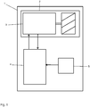
- the blower is part of a known vacuum cleaner 1, which in the FIG. 1 merely sketched with its essential parts for the invention as a block diagram.
- an electronic control device 4 is assigned to set the blower power to the motor 3 of the blower 2. This acts, for example, when a universal motor is used, via a power semiconductor by means of a phase or section control on the power of the motor.
- the phase angle is the manipulated variable of the control device 4.
- the vacuum generated by the blower 2 is used.
- a fixed setpoint is predetermined by using a negative pressure switch 5, which has only a single switching point, so that this switching point corresponds to the setpoint value to determine the actual value.
- the switch 5 may be arranged at a suitable location of the vacuum cleaner 1, for example in the region of the coupling of a suction hose to the vacuum cleaner housing (both not shown).
- FIGS. 2 to 6 Diagrams are shown showing the set fan power as a function of time.
- the blower output is at an initial value P start , see FIG. 2 .
- P start initial value
- FIG. 2 This is followed by a first operating phase I (see Figures 5 ), in which the control device 4 is looking for an operating point for the blower motor 3, in which the generated negative pressure is in the range of the switching point of the vacuum switch 5.
- Initial value may be a power P start , which emits the fan when switching on the vacuum cleaner due to a default setting or also because of the stored value last generated at the last suction.
- the initial value can also be the power P Start_new , which generates the fan shortly before a pressure change during operation (Note: The pressure change causes a significant change in the actual size and conditionally a new search of the working point).
- the control device 4 changes the manipulated variable and thus the fan power with a high, preferably maximum speed starting from the initial value P Start , see FIG. 2 .
- the change takes place as a function of the switching state of the vacuum switch 5, ie with open vacuum switch 5, the manipulated variable is increased because the desired negative pressure is not reached, and with closed vacuum switch 5, the manipulated variable is reduced because the negative pressure is already too high.
- the method according to the invention is described in the case of an opened vacuum switch 5, see FIGS.
- FIG. 6 shows in a summary of the processes with closed vacuum switch 5.
- the controller 4 only knows the initial value P Start and the performance limits of the system, ie a maximum value P Max and a minimum value P Min . With the vacuum switch open, the target area is initially between P Start and P Max .
- the control device 4 determines two characteristic of the position of the switching point parameters, namely the difference .DELTA.P between P Max and the power P UDS in the switching point of the vacuum switch and the time t UDS , for changing the manipulated variable from the initial value (P start ) to the switching change ( P UDS ) of the vacuum switch 5 is required. Subsequently, the target area is further limited based on these parameters.
- the upper limit, originally P Max is first lowered by ⁇ P, then the upper limit is reduced by a further amount of power, namely by the value t UDS • y.
- t UDS is the time to change the manipulated variable from the initial value (P Start ) to the change of switching (P UDS ) of the vacuum switch y is a determinable by experiments constant with the unit of measure W / sec
- the lower limit will be around the value x / .DELTA.P raised.
- x another, determinable by experiments constant with the unit of measure W 2 ⁇ P is the difference ⁇ P between P Max and the power P UDS at the switching point of the vacuum switch
- the in FIG. 4 identified limited target area determined.
- the mean value of this target area is assumed to be the operating point of the blower (see also FIG. 4 ) and started immediately (see FIG. 5 ).
- the manipulated variable is changed only slowly.
- the manipulated variable is gradually reduced, until the vacuum switch 5 opens.
- the manipulated variable is increased again until the vacuum switch 5 closes, etc.
- the blower power influenced by the manipulated variable thus oscillates at a low frequency around the operating point. If, during the suction process, the working conditions are changed, for example, by raising the nozzle or changing the machined substrate, the negative pressure generated by the fan and thus the working point also change.
- a shift of the operating point has the consequence that an opening or closing of the vacuum switch 5 does not happen after a predetermined number of manipulated variable changes (steps).
- the control device 4 recognizes this and starts a new first operating phase I '. Im in FIG. 5 As shown, the vacuum switch 5 is closed. Therefore, in the operating phase I ', the power is first of all rapidly reduced.
- FIG. 6 summarized shows the determination of the operating point in such a case.
- the lower limit of the target range of P min becomes the value P Min + ⁇ P + t UDS • y raised.
- the upper limit of the target range is set by P Start Pstart - x / ⁇ P lowered.
- the mean value of the target area is calculated and adopted as a new operating point. Thereafter, the switching to the second operating phase II ', which is carried out analogously to the second operating phase II.
- a special case occurs when the maximum or minimum adjustable power is reached in the first operating phase, without a switching change of the vacuum switch 5 takes place. Then the operating point is close to P Max or P Min and neither a target range nor an average can be calculated. The control device 4 then takes as an operating point the upper or lower limit P Max or P Min and holds the control variable to the maximum or minimum adjustable value. Subsequently, the second operating phase is performed. It can be done at the beginning of the second phase of operation after a time t 1 nor a switching change, if in the first phase of operation, the switching change was not reached only because of the overshoot. Then the controller 4 calculates an operating point at P Max - z / t 1 or at P min + z / t 1 lies. In this case, z is a constant that can be determined in experiments.
Landscapes
- Engineering & Computer Science (AREA)
- Physics & Mathematics (AREA)
- Mechanical Engineering (AREA)
- Fluid Mechanics (AREA)
- General Physics & Mathematics (AREA)
- Automation & Control Theory (AREA)
- Electric Vacuum Cleaner (AREA)
Abstract
Description
- Die Erfindung betrifft ein Verfahren zum Einstellen der Leistung eines Staubsaugergebläses, bei dem eine elektronische Regeleinrichtung die Gebläseleistung mittels einer geeigneten Stellgröße in Abhängigkeit eines vom Gebläse erzeugten Unterdrucks als Regelgröße einstellt, wobei der Unterdruck mittels eines Unterdruckschalters mit einem einzigen Schaltpunkt ermittelt wird, und wobei die Regeleinrichtung in einer ersten Betriebsphase nach dem Einschalten des Gebläses oder nach einer Änderung des Unterdrucks die Stellgröße schnell von einem Anfangswert bis zu einem Schaltwechsel des Unterdruckschalters ändert und in einer zweiten Betriebsphase die Stellgröße langsam um den Schaltpunkt herum ändert.
- Hochwertige Staubsauger besitzen eine automatische Regelung der Saugleistung. Hierdurch soll einerseits die zum Bewegen der Bodendüse notwendigen Schiebekräfte gering gehalten und andererseits die Leistung an den zu reinigenden Bodenbelag angepasst werden. Dabei erfolgt die Regelung in Abhängigkeit von dem gemessenen Unterdruck als Regelgröße, der an einer charakteristischen Stelle wie der Bodendüse oder dem Saugstutzen gemessen wird. Zur Erfassung des Unterdrucks kommen als Sensoren Unterdruckschalter mit analoger Ausgabe, Unterdruckschalter mit zwei Schaltpunkten oder Unterdruckschalter mit einem einzigen Schaltpunkt zum Einsatz. Als Stellgröße zur Änderung der Leistung wird beispielsweise eine Phasenanschnittsteuerung verwendet. Die Auswertung der Sensorik und die Einstellung der Stellgröße sowie gegebenenfalls weitere Messungen erfolgen üblicherweise mit einem Mikrocontroller, im Folgenden allgemein als elektronische Regeleinrichtung bezeichnet.
- Unterdruckschalter mit analoger Ausgabe besitzen den Vorteil, dass sie eine exakte Messung der Sollwertabweichung zu jeder Zeit ermöglichen. Dementsprechend haben sie das beste Regelverhalten, sie sind schnell und genau. Dieser Vorteil wird durch einen sehr hohen Bauteilpreis erkauft. Unterdruckschalter mit zwei Schaltpunkten (oder alternativ zwei Unterdruckschalter mit unterschiedlichen Schaltpunkten) stellen eine günstigere Variante dar: Der Sollwert der Regelgröße liegt zwischen den beiden Schaltpunkten (Unterdruckwerten) und die Gebläseleistung kann durch gezielte Änderung sicher in den gewünschten Zielbereich gefahren werden. Die Abweichung vom Sollwertbereich ist zwar nicht mehr quantitativ erfassbar, es kann aber durch Regelalgorithmen ein Überschwingen verhindert werden (siehe beispielsweise
DE 44 33 181 C2 ). Die eingestellte Leistung schwankt so im Sollwertbereich zwischen den zwei Schaltpunkten. - Die einfachste und preiswerteste Saugleistungsregelung unter Verwendung eines Unterdruckschalters mit nur einem Schaltpunkt ist dadurch möglich, dass die Leistung permanent um diesen Schaltpunkt herum geregelt wird. Damit wird mit einem einfacheren Unterdruckschalter das Verhalten des Zwei-Punkt-Schalters nachgebildet, allerdings mit einigen Nachteilen. Bei einer Regelung mit hoher Dynamik schwingt die eingestellte Leistung sehr stark, dies führt zu einer ungewollten Geräuschentwicklung, bei der der Benutzer ein Heulen wahrnimmt. Bei geringerer Dynamik ist die Regelung stabiler und schwingt weniger, reagiert aber auf Druckänderungen, beispielsweise beim Wechseln von Bodenbelägen oder beim Anheben der Bodendüse entsprechend langsam, was ebenfalls als störend empfunden wird. Die Automatik wirkt zu träge.
- In neueren Staubsaugern ist es deshalb üblich, zur Regelung der Saugleistung zwischen zwei Betriebsbereichen zu unterscheiden, und zwar zwischen einem ersten Bereich, in dem der Arbeitspunkt des Gebläses gesucht wird, und einem zweiten Bereich, in dem die Regeleinrichtung auf einen Betrieb mit geringerer Dynamik umschaltet. Bei dem derzeit verwendeten Verfahren zur Suche des Arbeitspunkts wird die Leistung mit hoher Geschwindigkeit zur Änderung des Unterdruckschalters zunächst in eine Richtung geändert - wenn der Schalter geschlossen ist, wird die Leistung abgesenkt, wenn der Schalter geöffnet ist, wird die Leistung erhöht - nach dem Schaltwechsel des Unterdruckschalters wird die Leistung wieder in die jeweils andere Richtung gestellt, bis erneut ein Schaltwechsel eintritt. Bei dieser Prozedur wird der Leistungswert der beiden Schaltwechsel gespeichert und der Mittelwert aus den beiden Werten gebildet. Dieser Mittelwert wird anschließend als Sollwert angenommen und die entsprechende Leistung eingestellt. Nachteilig an dieser Lösung ist das geräuschvolle Hoch- und Runterfahren der Leistung während der Arbeitspunktsuche, das einem Defekt der Regelung ähnlich klingt.
- Der Erfindung stellt sich somit das Problem, ein Verfahren zum Einstellen der Leistung eines Staubsaugergebläses der eingangs genannten Art zu offenbaren, bei dem die Ermittlung des Arbeitspunkts schneller und mit geringerer Geräuschentwicklung möglich ist.
- Erfindungsgemäß wird dieses Problem durch ein Verfahren mit den Merkmalen des Patentanspruchs 1 gelöst. Vorteilhafte Ausgestaltungen und Weiterbildungen der Erfindung ergeben sich aus den nachfolgenden Unteransprüchen.
- Die mit der Erfindung erreichbaren Vorteile ergeben sich dadurch, dass die Regeleinrichtung in der ersten Betriebsphase für die Lage des Schaltpunkts des Unterdruckschalters charakteristische Parameter ermittelt und hieraus den Arbeitspunkt des Gebläses bestimmt, und dass die Regeleinrichtung in der zweiten Betriebsphase die Stellgröße derart ändert, dass unverzüglich der Arbeitspunkt des Gebläses angefahren wird. Hierdurch wird sehr schnell ein stabiler Zustand erreicht, in dem die Regeleinrichtung die Regelung mit einer geringeren Dynamik betreiben kann.
- Es ist zweckmäßig, wenn die Regeleinrichtung die benötigte Zeit zum Ändern der Stellgröße vom Anfangswert bis zum Schaltwechsel des Unterdruckschalters ermittelt. Zusätzlich kann noch die Regeleinrichtung die Differenz der maximal erreichbaren Gebläseleistung und der beim Schaltwechsel des Unterdruckschalters erreichten Gebläseleistung bzw. die Differenz der entsprechenden Stellgrößen ermitteln.
- In einer vorteilhaften Ausführungsform bestimmt die Regeleinrichtung aus den für die Lage des Schaltpunkts des Unterdruckschalters charakteristischen Parametern zunächst einen Zielbereich und nimmt dann den Arbeitspunkt als Mitte des Zielbereichs an.
- Ein Ausführungsbeispiel der Erfindung wird nachfolgend näher beschrieben. Die
Figuren 2 bis 6 zeigen Diagramme, anhand derer der Ablauf der Saugleistungsregelung bei einem Staubsaugergebläse 2 rein schematisch dargestellt ist. Das Gebläse ist Bestandteil eines an sich bekannten Staubsaugers 1, der in derFigur 1 lediglich mit seinen für die Erfindung wesentlichen Teilen als Blockschaltbild skizziert ist. Zur Einstellung der Gebläseleistung ist dem Motor 3 des Gebläses 2 eine elektronische Regeleinrichtung 4 zugeordnet. Diese wirkt beispielsweise dann, wenn ein Universalmotor zum Einsatz kommt, über einen Leistungshalbleiter mittels einer Phasenan- oder -abschnittsteuerung auf die Stromversorgung des Motors ein. In diesem Fall ist der Phasenwinkel die Stellgröße der Regeleinrichtung 4. Als Regelgröße, mit der die Regeleinrichtung 4 arbeitet, dient der vom Gebläse 2 erzeugte Unterdruck. Es wird ein fester Sollwert vorgegeben, indem zur Ermittlung des Istwerts ein Unterdruckschalterschalter 5 verwendet wird, welcher nur einen einzigen Schaltpunkt besitzt, so dass dieser Schaltpunkt dem Sollwert entspricht. Der Schalter 5 kann an einer geeigneten Stelle des Staubsaugers 1 angeordnet sein, beispielsweise im Bereich der Ankopplung eines Saugschlauchs an das Staubsaugergehäuse (beide nicht dargestellt). - Im Folgenden ist die Arbeitsweise der Regeleinrichtung 4 beschrieben. In den
Figuren 2 bis 6 werden Diagramme gezeigt, die die eingestellte Gebläseleistung in Abhängigkeit von der Zeit wiedergeben. Zunächst einmal befindet sich die Gebläseleistung auf einem Anfangswert Pstart, sieheFigur 2 . Hieran schließt sich eine erste Betriebsphase I (sieheFiguren 5 ) an, in der die Regeleinrichtung 4 einen Arbeitspunkt für den Gebläsemotor 3 sucht, in dem der erzeugte Unterdruck im Bereich des Schaltpunkt des Unterdruckschalters 5 liegt. Anfangswert kann eine Leistung Pstart sein, die das Gebläse beim Einschalten des Staubsaugers aufgrund einer Voreinstellung oder aber auch aufgrund des gespeicherten, beim letzten Saugvorgang zuletzt erzeugten Werts abgibt. Anfangswert kann aber auch die Leistung PStart_neu sein, die das Gebläse während des Betriebs kurz vor einer Druckänderung erzeugt (Anm.: Die Druckänderung verursacht eine signifikante Änderung der Istgröße und bedingt dadurch eine erneute Suche des Arbeitspunkts). In dieser ersten Betriebsphase ändert die Regeleinrichtung 4 die Stellgröße und damit die Gebläseleistung mit großer, vorzugsweise maximaler Geschwindigkeit ausgehend vom Anfangswert PStart, sieheFigur 2 . Die Änderung erfolgt in Abhängigkeit vom Schaltzustand des Unterdruckschalters 5, d. h. bei geöffnetem Unterdruckschalter 5 wird die Stellgröße erhöht, da der gewünschte Unterdruck noch nicht erreicht ist, und bei geschlossenem Unterdruckschalter 5 wird die Stellgröße verringert, da der Unterdruck bereits zu hoch ist. Im Folgenden wird das erfindungsgemäße Verfahren bei einem geöffneten Unterdruckschalter 5 beschrieben, sieheFiguren 2 bis 5 , lediglich dieFigur 6 zeigt in einer Zusammenfassung die Vorgänge bei geschlossenem Unterdruckschalter 5. Zu Beginn der ersten Betriebsphase kennt die Regeleinrichtung 4 lediglich den Anfangswert PStart und die Leistungsgrenzen des Systems, d. h. einen Maximalwert PMax und einen Minimalwert PMin. Der Zielbereich liegt bei geöffnetem Unterdruckschalter zunächst zwischen PStart und PMax. - Während des Leistungsanstiegs wird dann der Schaltpunkt des Unterdruckschalters 5 erreicht und der Schalter 5 schließt. Die Regeleinrichtung 4 ermittelt zwei für die Lage des Schaltpunkts charakteristische Parameter, nämlich die Differenz ΔP zwischen PMax und der Leistung PUDS im Schaltpunkt des Unterdruckschalters und die Zeit tUDS, die zum Ändern der Stellgröße vom Anfangswert (PStart) bis zum Schaltwechsel (PUDS) des Unterdruckschalters 5 benötigt wird. Anschließend wird auf Basis dieser Parameter der Zielbereich weiter eingegrenzt. Die Obergrenze, ursprünglich PMax, wird zunächst um ΔP abgesenkt, anschließend wird die Obergrenze um einen weiteren Leistungsbetrag verringert, und zwar um den Wert
tUDS•y.
Dabei sind
tUDS die Zeit zum Ändern der Stellgröße vom Anfangswert (PStart) bis zum Schaltwechsel (PUDS) des Unterdruckschalters
y eine durch Versuche bestimmbare Konstante mit der Maßeinheit W/sec - Die Untergrenze wird um den Wert
x/ΔP
angehoben. Dabei sind
x eine weitere, durch Versuche bestimmbare Konstante mit der Maßeinheit W2
Δ P die Differenz ΔP zwischen PMax und der Leistung PUDS im Schaltpunkt des Unterdruckschalters - Auf diese Weise wird der in
Figur 4 dargestellte eingegrenzte Zielbereich ermittelt. Anschließend wird der Mittelwert dieses Zielbereichs als Arbeitspunkt des Gebläses angenommen (siehe auchFigur 4 ) und unverzüglich angefahren (sieheFigur 5 ). Dann wird die Stellgröße nur noch langsam geändert. Die Stellgröße wird jeweils stufenweise verringert, bis sich der Unterdruckschalter 5 öffnet. Dann wird die Stellgröße wieder erhöht, bis der Unterdruckschalter 5 schließt usw. Die durch die Stellgröße beeinflusste Gebläseleistung schwingt demzufolge mit geringer Frequenz um den Arbeitspunkt herum. Werden während des Saugvorgangs die Arbeitsbedingungen beispielsweise durch Anheben der Düse oder Wechseln des bearbeiteten Untergrunds geändert, ändert sich auch der vom Gebläse erzeugte Unterdruck und damit der Arbeitspunkt. Eine Verschiebung des Arbeitspunktes hat zur Folge, dass ein Öffnen oder Schließen des Unterdruckschalters 5 nicht nach einer vorgegebenen Anzahl von Stellgrößenänderungen (Schritten) geschieht. Die Regeleinrichtung 4 erkennt dies und startet eine neue erste Betriebsphase I'. Im inFigur 5 gezeigten Beispiel ist der Unterdruckschalter 5 geschlossen. Deshalb wird in der Betriebsphase I' die Leistung zunächst einmal schnell verringert.Figur 6 zeigt zusammengefasst die Ermittlung des Arbeitspunkts in einem solchen Fall. Dabei wird die Untergrenze des Zielbereichs von PMin auf den Wert
PMin + ΔP + tUDS•y
angehoben. Die Obergrenze des Zielbereichs wird von PStart auf
Pstart - x/ΔP
abgesenkt. Anschließend wird der Mittelwert des Zielbereichs berechnet und als neuer Arbeitspunkt angenommen. Danach erfolgt das Umschalten auf die zweite Betriebsphase II', die analog zur zweiten Betriebsphase II durchgeführt wird. - Ein Sonderfall tritt auf, wenn in der ersten Betriebsphase die maximal oder minimal einstellbare Leistung erreicht wird, ohne dass ein Schaltwechsel des Unterdruckschalters 5 erfolgt. Dann liegt der Arbeitspunkt in der Nähe von PMax bzw. PMin und es kann weder ein Zielbereich noch ein Mittelwert errechnet werden. Die Regeleinrichtung 4 nimmt dann als Arbeitspunkt die Ober- bzw. Untergrenze PMax bzw. PMin an und hält die Stellgröße auf dem maximal bzw. minimal einstellbaren Wert. Anschließend wird die zweite Betriebsphase durchgeführt. Es kann zu Beginn der zweiten Betriebsphase nach einer Zeit t1 noch ein Schaltwechsel erfolgen, wenn in der ersten Betriebsphase der Schaltwechsel nur wegen des Überschwingens nicht erreicht wurde. Dann errechnet die Regeleinrichtung 4 einen Arbeitspunkt, der bei
PMax - z/t1
bzw. bei
PMin + z/t1
liegt. Dabei ist z eine in Versuchen ermittelbare Konstante.
Claims (4)
- Verfahren zum Einstellen der Leistung eines Staubsaugergebläses (2), bei dem eine elektronische Regeleinrichtung (4) die Gebläseleistung mittels einer geeigneten Stellgröße in Abhängigkeit eines vom Gebläse erzeugten Unterdrucks als Regelgröße einstellt, wobei der Unterdruck mittels eines Unterdruckschalters (5) mit einem einzigen Schaltpunkt ermittelt wird, und wobei die Regeleinrichtung (4) in einer ersten Betriebsphase (I, I') nach dem Einschalten des Gebläses (2) oder nach einer Änderung des Unterdrucks die Stellgröße schnell von einem Anfangswert (Pstart) bis zu einem Schaltwechsel des Unterdruckschalters (4) ändert und in einer zweiten Betriebsphase (II, II') die Stellgröße langsam um den Schaltpunkt herum ändert,
dadurch gekennzeichnet,
dass die Regeleinrichtung (4) in der ersten Betriebsphase (I, I') für die Lage des Schaltpunkts des Unterdruckschalters (5) charakteristische Parameter ermittelt und hieraus den Arbeitspunkt des Gebläses bestimmt, und dass die Regeleinrichtung (4) in der zweiten Betriebsphase (II, II') die Stellgröße derart ändert, dass unverzüglich der Arbeitspunkt des Gebläses angefahren wird. - Verfahren nach Anspruch 1,
dadurch gekennzeichnet,
dass die Regeleinrichtung (4) die benötigte Zeit (tUDS) zum Ändern der Stellgröße vom Anfangswert (PStart) bis zum Schaltwechsel (PUDS) des Unterdruckschalters (5) ermittelt. - Verfahren nach Anspruch 2,
dadurch gekennzeichnet,
dass die Regeleinrichtung (4) die Differenz (ΔP) zwischen der maximal erreichbaren Gebläseleistung und der beim Schaltwechsel des Unterdruckschalters (5) erreichten Gebläseleistung bzw. die Differenz der entsprechenden Stellgrößen ermittelt. - Verfahren nach mindestens einem der Ansprüche 1 bis 3,
dadurch gekennzeichnet,
dass die Regeleinrichtung (4) aus den für die Lage des Schaltpunkts des Unterdruckschalters (5) charakteristischen Parametern zunächst einen Zielbereich bestimmt und hieraus den Arbeitspunkt als Mitte des Zielbereichs annimmt.
Priority Applications (1)
| Application Number | Priority Date | Filing Date | Title |
|---|---|---|---|
| EP20120401010 EP2620086B1 (de) | 2012-01-27 | 2012-01-27 | Verfahren zum Einstellen der Leistung eines Staubsaugergebläses |
Applications Claiming Priority (1)
| Application Number | Priority Date | Filing Date | Title |
|---|---|---|---|
| EP20120401010 EP2620086B1 (de) | 2012-01-27 | 2012-01-27 | Verfahren zum Einstellen der Leistung eines Staubsaugergebläses |
Publications (2)
| Publication Number | Publication Date |
|---|---|
| EP2620086A1 true EP2620086A1 (de) | 2013-07-31 |
| EP2620086B1 EP2620086B1 (de) | 2014-03-26 |
Family
ID=45592287
Family Applications (1)
| Application Number | Title | Priority Date | Filing Date |
|---|---|---|---|
| EP20120401010 Not-in-force EP2620086B1 (de) | 2012-01-27 | 2012-01-27 | Verfahren zum Einstellen der Leistung eines Staubsaugergebläses |
Country Status (1)
| Country | Link |
|---|---|
| EP (1) | EP2620086B1 (de) |
Cited By (1)
| Publication number | Priority date | Publication date | Assignee | Title |
|---|---|---|---|---|
| DE102013102847A1 (de) | 2013-03-20 | 2014-09-25 | Miele & Cie. Kg | Verfahren zum Einstellen der Leistung eines Staubsaugergebläses, Regelungseinrichtung zur Umsetzung des Verfahrens und Staubsauger mit einer solchen Regelungseinrichtung |
Citations (4)
| Publication number | Priority date | Publication date | Assignee | Title |
|---|---|---|---|---|
| EP0379680A1 (de) * | 1989-01-21 | 1990-08-01 | Interlava AG | Vorrichtung zur automatischen Saugleistungssteuerung eines Staubsaugers |
| DE4433181A1 (de) * | 1994-09-17 | 1996-03-21 | Miele & Cie | Verfahren zur Vermeidung von Überschwingungen bei der automatischen Saugleistungsregelung eines Staubsaugers |
| US5722109A (en) * | 1993-07-28 | 1998-03-03 | U.S. Philips Corporation | Vacuum cleaner with floor type detection means and motor power control as a function of the detected floor type |
| WO2009103585A1 (de) * | 2008-02-20 | 2009-08-27 | BSH Bosch und Siemens Hausgeräte GmbH | Vorrichtung zur automatischen saugleistungsregelung eines staubsaugers |
-
2012
- 2012-01-27 EP EP20120401010 patent/EP2620086B1/de not_active Not-in-force
Patent Citations (5)
| Publication number | Priority date | Publication date | Assignee | Title |
|---|---|---|---|---|
| EP0379680A1 (de) * | 1989-01-21 | 1990-08-01 | Interlava AG | Vorrichtung zur automatischen Saugleistungssteuerung eines Staubsaugers |
| US5722109A (en) * | 1993-07-28 | 1998-03-03 | U.S. Philips Corporation | Vacuum cleaner with floor type detection means and motor power control as a function of the detected floor type |
| DE4433181A1 (de) * | 1994-09-17 | 1996-03-21 | Miele & Cie | Verfahren zur Vermeidung von Überschwingungen bei der automatischen Saugleistungsregelung eines Staubsaugers |
| DE4433181C2 (de) | 1994-09-17 | 1999-06-17 | Miele & Cie | Verfahren zur Vermeidung von Überschwingungen bei der automatischen Saugleistungsregelung eines Staubsaugers |
| WO2009103585A1 (de) * | 2008-02-20 | 2009-08-27 | BSH Bosch und Siemens Hausgeräte GmbH | Vorrichtung zur automatischen saugleistungsregelung eines staubsaugers |
Cited By (1)
| Publication number | Priority date | Publication date | Assignee | Title |
|---|---|---|---|---|
| DE102013102847A1 (de) | 2013-03-20 | 2014-09-25 | Miele & Cie. Kg | Verfahren zum Einstellen der Leistung eines Staubsaugergebläses, Regelungseinrichtung zur Umsetzung des Verfahrens und Staubsauger mit einer solchen Regelungseinrichtung |
Also Published As
| Publication number | Publication date |
|---|---|
| EP2620086B1 (de) | 2014-03-26 |
Similar Documents
| Publication | Publication Date | Title |
|---|---|---|
| DE19952578B4 (de) | Vorrichtung und Verfahren zum Steuern eines Linearverdichters | |
| EP3055116B1 (de) | Verfahren zur prozessführung eines formfüllvorgangs einer spritzgiessmaschine | |
| EP2222215B1 (de) | Vorrichtung zur steuerung oder regelung der motorleistung eines staubsaugers | |
| DE102019220501A1 (de) | Verfahren zum Steuern eines hydraulischen Zylinders einer Arbeitsmaschine | |
| EP1965158A2 (de) | Verfahren zum Kalibrieren einer Kälteanlage und eine Kälteanlage | |
| EP0243527B1 (de) | Verfahren zur Regelung und/oder Steuerung des Druckes in einem Rezipienten | |
| EP0336095B1 (de) | Regelverfahren zum Vermeiden des Pumpens eines Turboverdichters mittels bedarfsweisen Abblasens | |
| EP1254403B1 (de) | Verfahren zur steuerung eines proportional-magneten mit haltefunktion | |
| DE102021206492B4 (de) | Prozessventilvorrichtung und Verfahren | |
| EP2620086B1 (de) | Verfahren zum Einstellen der Leistung eines Staubsaugergebläses | |
| WO2018087307A1 (de) | Elektropneumatisches steuerungssystem und stellungsregler für ein derartiges system | |
| EP1987573B1 (de) | Verfahren zur begrenzung der überschusskraft eines fremdkraftbetätigten schliessteils | |
| DE202011052171U1 (de) | Kühlmittelsystem für Werkzeugmaschinen | |
| EP4081871B1 (de) | Steuerungsverfahren für ein teilelektronisches system | |
| DE4433181A1 (de) | Verfahren zur Vermeidung von Überschwingungen bei der automatischen Saugleistungsregelung eines Staubsaugers | |
| AT516879B1 (de) | Verfahren zum Betrieb eines Einspritzaggregats und Einspritzaggregat | |
| DE102012112710A1 (de) | System und Verfahren zur Regelung eines Ventils | |
| EP2781179B1 (de) | Verfahren zum Einstellen der Leistung eines Staubsaugergebläses, Regelungseinrichtung zur Umsetzung des Verfahrens und Staubsauger mit einer solchen Regelungseinrichtung | |
| EP2053249B1 (de) | Anordnung mit Vakuumpumpe und Verfahren | |
| DE4434392C1 (de) | Verfahren und Steuerungsvorrichtung zum Ermitteln des Füllungszustandes einer Füllvorrichtung | |
| DE102024134421B3 (de) | Verfahren zur Ermittlung wenigstens einer Kenngröße einer Prozessventil-Baueinheit und Prozessventil-Baueinheit | |
| DE102008011111A1 (de) | Verfahren und Vorrichtung zum Abgleich einer Regeleinrichtung | |
| DE102015016017B4 (de) | Kraftfahrzeug und Verfahren zum Betrieb eines Kraftfahrzeugs | |
| EP4229490B1 (de) | Verfahren und vorrichtungen zum regeln einer hoch dynamischen regelstrecke mit fluidischem antrieb mithilfe eines ratenbegrenzers | |
| AT528375A1 (de) | Regelungsverfahren für eine Regelung einer Ventilposition des Regelungsventils für eine Regelung eines Gasstroms, insbesondere in einem Brennstoffzellensystem |
Legal Events
| Date | Code | Title | Description |
|---|---|---|---|
| PUAI | Public reference made under article 153(3) epc to a published international application that has entered the european phase |
Free format text: ORIGINAL CODE: 0009012 |
|
| AK | Designated contracting states |
Kind code of ref document: A1 Designated state(s): AL AT BE BG CH CY CZ DE DK EE ES FI FR GB GR HR HU IE IS IT LI LT LU LV MC MK MT NL NO PL PT RO RS SE SI SK SM TR |
|
| AX | Request for extension of the european patent |
Extension state: BA ME |
|
| 17P | Request for examination filed |
Effective date: 20130704 |
|
| RBV | Designated contracting states (corrected) |
Designated state(s): AL AT BE BG CH CY CZ DE DK EE ES FI FR GB GR HR HU IE IS IT LI LT LU LV MC MK MT NL NO PL PT RO RS SE SI SK SM TR |
|
| GRAP | Despatch of communication of intention to grant a patent |
Free format text: ORIGINAL CODE: EPIDOSNIGR1 |
|
| RIC1 | Information provided on ipc code assigned before grant |
Ipc: G05D 16/20 20060101ALI20131119BHEP Ipc: A47L 9/28 20060101AFI20131119BHEP |
|
| INTG | Intention to grant announced |
Effective date: 20131211 |
|
| GRAS | Grant fee paid |
Free format text: ORIGINAL CODE: EPIDOSNIGR3 |
|
| GRAA | (expected) grant |
Free format text: ORIGINAL CODE: 0009210 |
|
| AK | Designated contracting states |
Kind code of ref document: B1 Designated state(s): AL AT BE BG CH CY CZ DE DK EE ES FI FR GB GR HR HU IE IS IT LI LT LU LV MC MK MT NL NO PL PT RO RS SE SI SK SM TR |
|
| REG | Reference to a national code |
Ref country code: GB Ref legal event code: FG4D Free format text: NOT ENGLISH |
|
| REG | Reference to a national code |
Ref country code: CH Ref legal event code: EP |
|
| REG | Reference to a national code |
Ref country code: DE Ref legal event code: R084 Ref document number: 502012000510 Country of ref document: DE |
|
| REG | Reference to a national code |
Ref country code: AT Ref legal event code: REF Ref document number: 658482 Country of ref document: AT Kind code of ref document: T Effective date: 20140415 |
|
| REG | Reference to a national code |
Ref country code: IE Ref legal event code: FG4D Free format text: LANGUAGE OF EP DOCUMENT: GERMAN |
|
| REG | Reference to a national code |
Ref country code: DE Ref legal event code: R096 Ref document number: 502012000510 Country of ref document: DE Effective date: 20140508 |
|
| REG | Reference to a national code |
Ref country code: DE Ref legal event code: R084 Ref document number: 502012000510 Country of ref document: DE Effective date: 20140403 |
|
| REG | Reference to a national code |
Ref country code: GB Ref legal event code: 746 Effective date: 20140625 |
|
| PG25 | Lapsed in a contracting state [announced via postgrant information from national office to epo] |
Ref country code: LT Free format text: LAPSE BECAUSE OF FAILURE TO SUBMIT A TRANSLATION OF THE DESCRIPTION OR TO PAY THE FEE WITHIN THE PRESCRIBED TIME-LIMIT Effective date: 20140326 Ref country code: NO Free format text: LAPSE BECAUSE OF FAILURE TO SUBMIT A TRANSLATION OF THE DESCRIPTION OR TO PAY THE FEE WITHIN THE PRESCRIBED TIME-LIMIT Effective date: 20140626 |
|
| REG | Reference to a national code |
Ref country code: NL Ref legal event code: VDEP Effective date: 20140326 |
|
| REG | Reference to a national code |
Ref country code: LT Ref legal event code: MG4D |
|
| PG25 | Lapsed in a contracting state [announced via postgrant information from national office to epo] |
Ref country code: FI Free format text: LAPSE BECAUSE OF FAILURE TO SUBMIT A TRANSLATION OF THE DESCRIPTION OR TO PAY THE FEE WITHIN THE PRESCRIBED TIME-LIMIT Effective date: 20140326 Ref country code: SE Free format text: LAPSE BECAUSE OF FAILURE TO SUBMIT A TRANSLATION OF THE DESCRIPTION OR TO PAY THE FEE WITHIN THE PRESCRIBED TIME-LIMIT Effective date: 20140326 |
|
| PG25 | Lapsed in a contracting state [announced via postgrant information from national office to epo] |
Ref country code: LV Free format text: LAPSE BECAUSE OF FAILURE TO SUBMIT A TRANSLATION OF THE DESCRIPTION OR TO PAY THE FEE WITHIN THE PRESCRIBED TIME-LIMIT Effective date: 20140326 Ref country code: RS Free format text: LAPSE BECAUSE OF FAILURE TO SUBMIT A TRANSLATION OF THE DESCRIPTION OR TO PAY THE FEE WITHIN THE PRESCRIBED TIME-LIMIT Effective date: 20140326 Ref country code: HR Free format text: LAPSE BECAUSE OF FAILURE TO SUBMIT A TRANSLATION OF THE DESCRIPTION OR TO PAY THE FEE WITHIN THE PRESCRIBED TIME-LIMIT Effective date: 20140326 |
|
| PG25 | Lapsed in a contracting state [announced via postgrant information from national office to epo] |
Ref country code: EE Free format text: LAPSE BECAUSE OF FAILURE TO SUBMIT A TRANSLATION OF THE DESCRIPTION OR TO PAY THE FEE WITHIN THE PRESCRIBED TIME-LIMIT Effective date: 20140326 Ref country code: NL Free format text: LAPSE BECAUSE OF FAILURE TO SUBMIT A TRANSLATION OF THE DESCRIPTION OR TO PAY THE FEE WITHIN THE PRESCRIBED TIME-LIMIT Effective date: 20140326 Ref country code: BG Free format text: LAPSE BECAUSE OF FAILURE TO SUBMIT A TRANSLATION OF THE DESCRIPTION OR TO PAY THE FEE WITHIN THE PRESCRIBED TIME-LIMIT Effective date: 20140626 Ref country code: CZ Free format text: LAPSE BECAUSE OF FAILURE TO SUBMIT A TRANSLATION OF THE DESCRIPTION OR TO PAY THE FEE WITHIN THE PRESCRIBED TIME-LIMIT Effective date: 20140326 Ref country code: IS Free format text: LAPSE BECAUSE OF FAILURE TO SUBMIT A TRANSLATION OF THE DESCRIPTION OR TO PAY THE FEE WITHIN THE PRESCRIBED TIME-LIMIT Effective date: 20140726 Ref country code: RO Free format text: LAPSE BECAUSE OF FAILURE TO SUBMIT A TRANSLATION OF THE DESCRIPTION OR TO PAY THE FEE WITHIN THE PRESCRIBED TIME-LIMIT Effective date: 20140326 Ref country code: CY Free format text: LAPSE BECAUSE OF FAILURE TO SUBMIT A TRANSLATION OF THE DESCRIPTION OR TO PAY THE FEE WITHIN THE PRESCRIBED TIME-LIMIT Effective date: 20140326 |
|
| PG25 | Lapsed in a contracting state [announced via postgrant information from national office to epo] |
Ref country code: SK Free format text: LAPSE BECAUSE OF FAILURE TO SUBMIT A TRANSLATION OF THE DESCRIPTION OR TO PAY THE FEE WITHIN THE PRESCRIBED TIME-LIMIT Effective date: 20140326 Ref country code: PL Free format text: LAPSE BECAUSE OF FAILURE TO SUBMIT A TRANSLATION OF THE DESCRIPTION OR TO PAY THE FEE WITHIN THE PRESCRIBED TIME-LIMIT Effective date: 20140326 Ref country code: ES Free format text: LAPSE BECAUSE OF FAILURE TO SUBMIT A TRANSLATION OF THE DESCRIPTION OR TO PAY THE FEE WITHIN THE PRESCRIBED TIME-LIMIT Effective date: 20140326 |
|
| PG25 | Lapsed in a contracting state [announced via postgrant information from national office to epo] |
Ref country code: PT Free format text: LAPSE BECAUSE OF FAILURE TO SUBMIT A TRANSLATION OF THE DESCRIPTION OR TO PAY THE FEE WITHIN THE PRESCRIBED TIME-LIMIT Effective date: 20140728 |
|
| REG | Reference to a national code |
Ref country code: DE Ref legal event code: R097 Ref document number: 502012000510 Country of ref document: DE |
|
| PG25 | Lapsed in a contracting state [announced via postgrant information from national office to epo] |
Ref country code: DK Free format text: LAPSE BECAUSE OF FAILURE TO SUBMIT A TRANSLATION OF THE DESCRIPTION OR TO PAY THE FEE WITHIN THE PRESCRIBED TIME-LIMIT Effective date: 20140326 |
|
| PLBE | No opposition filed within time limit |
Free format text: ORIGINAL CODE: 0009261 |
|
| STAA | Information on the status of an ep patent application or granted ep patent |
Free format text: STATUS: NO OPPOSITION FILED WITHIN TIME LIMIT |
|
| 26N | No opposition filed |
Effective date: 20150106 |
|
| REG | Reference to a national code |
Ref country code: DE Ref legal event code: R097 Ref document number: 502012000510 Country of ref document: DE Effective date: 20150106 |
|
| PG25 | Lapsed in a contracting state [announced via postgrant information from national office to epo] |
Ref country code: BE Free format text: LAPSE BECAUSE OF NON-PAYMENT OF DUE FEES Effective date: 20150131 |
|
| PG25 | Lapsed in a contracting state [announced via postgrant information from national office to epo] |
Ref country code: SI Free format text: LAPSE BECAUSE OF FAILURE TO SUBMIT A TRANSLATION OF THE DESCRIPTION OR TO PAY THE FEE WITHIN THE PRESCRIBED TIME-LIMIT Effective date: 20140326 |
|
| REG | Reference to a national code |
Ref country code: CH Ref legal event code: PL |
|
| PG25 | Lapsed in a contracting state [announced via postgrant information from national office to epo] |
Ref country code: LU Free format text: LAPSE BECAUSE OF FAILURE TO SUBMIT A TRANSLATION OF THE DESCRIPTION OR TO PAY THE FEE WITHIN THE PRESCRIBED TIME-LIMIT Effective date: 20150127 |
|
| PG25 | Lapsed in a contracting state [announced via postgrant information from national office to epo] |
Ref country code: MC Free format text: LAPSE BECAUSE OF FAILURE TO SUBMIT A TRANSLATION OF THE DESCRIPTION OR TO PAY THE FEE WITHIN THE PRESCRIBED TIME-LIMIT Effective date: 20140326 |
|
| PG25 | Lapsed in a contracting state [announced via postgrant information from national office to epo] |
Ref country code: LI Free format text: LAPSE BECAUSE OF NON-PAYMENT OF DUE FEES Effective date: 20150131 Ref country code: CH Free format text: LAPSE BECAUSE OF NON-PAYMENT OF DUE FEES Effective date: 20150131 |
|
| REG | Reference to a national code |
Ref country code: IE Ref legal event code: MM4A |
|
| REG | Reference to a national code |
Ref country code: FR Ref legal event code: PLFP Year of fee payment: 5 |
|
| PG25 | Lapsed in a contracting state [announced via postgrant information from national office to epo] |
Ref country code: IE Free format text: LAPSE BECAUSE OF NON-PAYMENT OF DUE FEES Effective date: 20150127 |
|
| PG25 | Lapsed in a contracting state [announced via postgrant information from national office to epo] |
Ref country code: GR Free format text: LAPSE BECAUSE OF FAILURE TO SUBMIT A TRANSLATION OF THE DESCRIPTION OR TO PAY THE FEE WITHIN THE PRESCRIBED TIME-LIMIT Effective date: 20140627 |
|
| PG25 | Lapsed in a contracting state [announced via postgrant information from national office to epo] |
Ref country code: MT Free format text: LAPSE BECAUSE OF FAILURE TO SUBMIT A TRANSLATION OF THE DESCRIPTION OR TO PAY THE FEE WITHIN THE PRESCRIBED TIME-LIMIT Effective date: 20140326 |
|
| REG | Reference to a national code |
Ref country code: FR Ref legal event code: PLFP Year of fee payment: 6 |
|
| PG25 | Lapsed in a contracting state [announced via postgrant information from national office to epo] |
Ref country code: SM Free format text: LAPSE BECAUSE OF FAILURE TO SUBMIT A TRANSLATION OF THE DESCRIPTION OR TO PAY THE FEE WITHIN THE PRESCRIBED TIME-LIMIT Effective date: 20140326 Ref country code: HU Free format text: LAPSE BECAUSE OF FAILURE TO SUBMIT A TRANSLATION OF THE DESCRIPTION OR TO PAY THE FEE WITHIN THE PRESCRIBED TIME-LIMIT; INVALID AB INITIO Effective date: 20120127 |
|
| PG25 | Lapsed in a contracting state [announced via postgrant information from national office to epo] |
Ref country code: TR Free format text: LAPSE BECAUSE OF FAILURE TO SUBMIT A TRANSLATION OF THE DESCRIPTION OR TO PAY THE FEE WITHIN THE PRESCRIBED TIME-LIMIT Effective date: 20140326 |
|
| REG | Reference to a national code |
Ref country code: FR Ref legal event code: PLFP Year of fee payment: 7 |
|
| REG | Reference to a national code |
Ref country code: AT Ref legal event code: MM01 Ref document number: 658482 Country of ref document: AT Kind code of ref document: T Effective date: 20170127 |
|
| PG25 | Lapsed in a contracting state [announced via postgrant information from national office to epo] |
Ref country code: AT Free format text: LAPSE BECAUSE OF NON-PAYMENT OF DUE FEES Effective date: 20170127 |
|
| PG25 | Lapsed in a contracting state [announced via postgrant information from national office to epo] |
Ref country code: MK Free format text: LAPSE BECAUSE OF FAILURE TO SUBMIT A TRANSLATION OF THE DESCRIPTION OR TO PAY THE FEE WITHIN THE PRESCRIBED TIME-LIMIT Effective date: 20140326 |
|
| PG25 | Lapsed in a contracting state [announced via postgrant information from national office to epo] |
Ref country code: AL Free format text: LAPSE BECAUSE OF FAILURE TO SUBMIT A TRANSLATION OF THE DESCRIPTION OR TO PAY THE FEE WITHIN THE PRESCRIBED TIME-LIMIT Effective date: 20140326 |
|
| P01 | Opt-out of the competence of the unified patent court (upc) registered |
Effective date: 20230529 |
|
| PGFP | Annual fee paid to national office [announced via postgrant information from national office to epo] |
Ref country code: DE Payment date: 20240131 Year of fee payment: 13 Ref country code: GB Payment date: 20240123 Year of fee payment: 13 |
|
| PGFP | Annual fee paid to national office [announced via postgrant information from national office to epo] |
Ref country code: IT Payment date: 20240123 Year of fee payment: 13 Ref country code: FR Payment date: 20240125 Year of fee payment: 13 |
|
| REG | Reference to a national code |
Ref country code: DE Ref legal event code: R119 Ref document number: 502012000510 Country of ref document: DE |
|
| GBPC | Gb: european patent ceased through non-payment of renewal fee |
Effective date: 20250127 |
|
| PG25 | Lapsed in a contracting state [announced via postgrant information from national office to epo] |
Ref country code: DE Free format text: LAPSE BECAUSE OF NON-PAYMENT OF DUE FEES Effective date: 20250801 |
|
| PG25 | Lapsed in a contracting state [announced via postgrant information from national office to epo] |
Ref country code: GB Free format text: LAPSE BECAUSE OF NON-PAYMENT OF DUE FEES Effective date: 20250127 |
|
| PG25 | Lapsed in a contracting state [announced via postgrant information from national office to epo] |
Ref country code: FR Free format text: LAPSE BECAUSE OF NON-PAYMENT OF DUE FEES Effective date: 20250131 |
|
| PG25 | Lapsed in a contracting state [announced via postgrant information from national office to epo] |
Ref country code: IT Free format text: LAPSE BECAUSE OF NON-PAYMENT OF DUE FEES Effective date: 20250127 |