EP2619082B1 - System zur steuerung eines wasserfahrzeugs mit lenkbaren doppelpropellern - Google Patents
System zur steuerung eines wasserfahrzeugs mit lenkbaren doppelpropellern Download PDFInfo
- Publication number
- EP2619082B1 EP2619082B1 EP11768206.2A EP11768206A EP2619082B1 EP 2619082 B1 EP2619082 B1 EP 2619082B1 EP 11768206 A EP11768206 A EP 11768206A EP 2619082 B1 EP2619082 B1 EP 2619082B1
- Authority
- EP
- European Patent Office
- Prior art keywords
- thrust
- drive
- drives
- steerable
- tie
- Prior art date
- Legal status (The legal status is an assumption and is not a legal conclusion. Google has not performed a legal analysis and makes no representation as to the accuracy of the status listed.)
- Active
Links
Images


Classifications
-
- B—PERFORMING OPERATIONS; TRANSPORTING
- B63—SHIPS OR OTHER WATERBORNE VESSELS; RELATED EQUIPMENT
- B63H—MARINE PROPULSION OR STEERING
- B63H25/00—Steering; Slowing-down otherwise than by use of propulsive elements; Dynamic anchoring, i.e. positioning vessels by means of main or auxiliary propulsive elements
- B63H25/42—Steering or dynamic anchoring by propulsive elements; Steering or dynamic anchoring by propellers used therefor only; Steering or dynamic anchoring by rudders carrying propellers
-
- B—PERFORMING OPERATIONS; TRANSPORTING
- B63—SHIPS OR OTHER WATERBORNE VESSELS; RELATED EQUIPMENT
- B63H—MARINE PROPULSION OR STEERING
- B63H20/00—Outboard propulsion units, e.g. outboard motors or Z-drives; Arrangements thereof on vessels
- B63H20/08—Means enabling movement of the position of the propulsion element, e.g. for trim, tilt or steering; Control of trim or tilt
- B63H20/10—Means enabling trim or tilt, or lifting of the propulsion element when an obstruction is hit; Control of trim or tilt
-
- B—PERFORMING OPERATIONS; TRANSPORTING
- B63—SHIPS OR OTHER WATERBORNE VESSELS; RELATED EQUIPMENT
- B63H—MARINE PROPULSION OR STEERING
- B63H20/00—Outboard propulsion units, e.g. outboard motors or Z-drives; Arrangements thereof on vessels
- B63H20/08—Means enabling movement of the position of the propulsion element, e.g. for trim, tilt or steering; Control of trim or tilt
- B63H20/12—Means enabling steering
-
- B—PERFORMING OPERATIONS; TRANSPORTING
- B63—SHIPS OR OTHER WATERBORNE VESSELS; RELATED EQUIPMENT
- B63H—MARINE PROPULSION OR STEERING
- B63H21/00—Use of propulsion power plant or units on vessels
- B63H21/21—Control means for engine or transmission, specially adapted for use on marine vessels
- B63H21/213—Levers or the like for controlling the engine or the transmission, e.g. single hand control levers
-
- B—PERFORMING OPERATIONS; TRANSPORTING
- B63—SHIPS OR OTHER WATERBORNE VESSELS; RELATED EQUIPMENT
- B63H—MARINE PROPULSION OR STEERING
- B63H1/00—Propulsive elements directly acting on water
- B63H1/02—Propulsive elements directly acting on water of rotary type
- B63H1/12—Propulsive elements directly acting on water of rotary type with rotation axis substantially in propulsive direction
- B63H1/14—Propellers
- B63H1/18—Propellers with means for diminishing cavitation, e.g. supercavitation
- B63H2001/185—Surfacing propellers, i.e. propellers specially adapted for operation at the water surface, with blades incompletely submerged, or piercing the water surface from above in the course of each revolution
-
- B—PERFORMING OPERATIONS; TRANSPORTING
- B63—SHIPS OR OTHER WATERBORNE VESSELS; RELATED EQUIPMENT
- B63H—MARINE PROPULSION OR STEERING
- B63H20/00—Outboard propulsion units, e.g. outboard motors or Z-drives; Arrangements thereof on vessels
- B63H2020/003—Arrangements of two, or more outboard propulsion units
-
- B—PERFORMING OPERATIONS; TRANSPORTING
- B63—SHIPS OR OTHER WATERBORNE VESSELS; RELATED EQUIPMENT
- B63H—MARINE PROPULSION OR STEERING
- B63H20/00—Outboard propulsion units, e.g. outboard motors or Z-drives; Arrangements thereof on vessels
- B63H2020/005—Arrangements of two or more propellers, or the like on single outboard propulsion units
Definitions
- the present disclosure relates to marine vessel propulsion and control systems. More particularly, aspects of the disclosure relate to methods and devices for controlling and allowing marine vessel steering drives to move freely with respect to each other but to also prevent such steering drives from colliding.
- propulsion Various forms of propulsion have been used to propel marine vessels over or through the water.
- One type of propulsion system comprises a prime mover, such as an engine or a turbine, which converts energy into a rotation that is transferred to one or more propellers having blades in contact with the surrounding water.
- the rotational energy in a propeller is transferred by contoured surfaces of the propeller blades into a force or "thrust" which propels the marine vessel.
- thrust and vessel motion are generated in the opposite direction.
- Many shapes and geometries for propeller-type propulsion systems are known.
- Other marine vessel propulsion systems utilize waterjet propulsion to achieve similar results.
- Such devices include a pump, a water inlet or suction port and an exit or discharge port, which generate a waterjet stream that propels the marine vessel.
- the waterjet stream may be deflected using a "deflector" to provide marine vessel control by redirecting some waterjet stream thrust in a suitable direction and in a suitable amount.
- a requirement for safe and useful operation of marine vessels is the ability to steer the vessel from side to side.
- Other systems for steering marine vessels, commonly used in waterjet-propelled vessels rotate the exit or discharge nozzle of the waterjet stream from one side to another. Such a nozzle is sometimes referred to as a "steering nozzle.”
- Hydraulic actuators may be used to rotate an articulated steering nozzle so that the aft end of the marine vessel experiences a sideways thrust in addition to any forward or backing force of the waterjet stream.
- the reaction of the marine vessel to the side-to-side movement of the steering nozzle will be in accordance with the laws of motion and conservation of momentum principles, and will depend on the dynamics of the marine vessel design.
- control surfaces are primarily designed to provide force or motion in a particular direction, these surfaces often also provide forces in other directions as well. Nonetheless, those skilled in the art appreciate that certain control surfaces and control and steering devices have a primary purpose to develop force or thrust along a particular axis. For example, in the case of a reversing deflector, it is the backing direction in which thrust is provided. Similarly, a rudder is intended to develop force at the stern portion of the vessel primarily in a side-to-side or athwart ships direction, even if collateral forces are developed in other directions. Thus, net force imparted to a marine vessel should be viewed as a vector sum process, where net or resultant force is generally the goal, and other smaller components thereof may be generated in other directions at the same time.
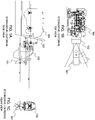
- FIG.s 1A-1C illustrate various views of a stern/out drive that can be used in combination
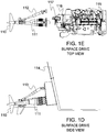
- FIG.s 1D-1E illustrate various views of a surface drive 111 that can be used in combination as outboard motors.
- twin-drive systems as well as systems comprising more than two drives.
- a quad-arrangement employing four drives, wherein a pair of drives is installed on each of two hulls of a catamaran hull form, is but one example of a system that can benefit from this disclosure.
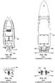
- FIG.s 2 A-2B A notional single-drive system is depicted in FIG.s 2 A-2B , and a notional twin-drive system is shown in FIG.s 2 C-2D .
- the twin-drive system illustrated in FIG.s 2 C-2D comprise a port stern drive 205 and starboard stern drive 206 and a mechanical link known as a tie-bar 207.
- the primary purpose of the tie bar 207 is to prevent the closely-spaced drives 205, 206 from colliding into each other in order to avoid damage to the craft or injury or death to persons onboard.
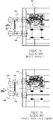
- the propellers 310, 311, 314 and 315 can be partially submerged for varying amounts of time, during which time the propellers can develop substantial lateral (athwartships) and vertical forces.
- the rotation of the at least two of the propellers typically opposes each other.
- a substantial net force is exerted on the tie-bar due to the substantially equal and opposite lateral forces generated by the propellers.
- tie bar 312 undergoes outward tension 313 when the propellers 310, 311 are outboard rotating; also as shown in FIG.
- tie bar 316 undergoes compression forces 317 if the propellers 314, 315 are inboard rotating.
- the lateral forces are substantially cancelled out and the steering drives are not subjected to any significant load associated with the lateral force component of the partially submerged propellers.
- a marine vessel control system which can provide thrust forces in a plurality of directions, and which can control thrust forces in a safe and efficient manner.
- One embodiment of the disclosure comprises an apparatus to be used with a marine vessel comprising a first steerable drive and a second steerable drive, the apparatus comprising a device, to be connected to the first steerable drive and to the second steerable drive, that provides for movement of the first and second steerable drives relative to each other and that also maintains a minimum distance between the first and second steerable drives so as to prevent the first and second steerable from contacting each other.
- One embodiment of the apparatus comprises a telescoping concentric tube assembly having a mechanical stop.
- Another embodiment comprises a sliding bar arrangement having a mechanical stop.
- Another embodiment comprises a first guard to be connected to the first steerable drive and a second guard to be coupled to the second steerable drive.
- Still another embodiment comprises an adaptive tie bar arrangement having a configurable length that can be controlled to allow movement of the first steerable drive and the second steerable drive with respect to each other and that also can be controlled to provide a fixed distance between the first and second steerable drives. It is to be appreciated that any of the embodiments can be used either alone or in combination.
- the adaptive tie bar arrangement can be any of a controllable mechanical locking device, a hydraulic locking device, and an electromechanical locking device. It is to be appreciated that any of these aspects can be used either alone or in combination with any of the embodiments disclosed herein.
- the apparatus further comprises a processor configured to receive at least a first vessel control signal corresponding to any of a rotational movement command, a translational movement command, and a combination of a rotational movement and a translational movement command, and configured to generate at least a first steerable drive actuator control signal and a second steerable drive actuator control signal, and a first trim actuator control signal and a second trim actuator control signal.
- a processor configured to receive at least a first vessel control signal corresponding to any of a rotational movement command, a translational movement command, and a combination of a rotational movement and a translational movement command, and configured to generate at least a first steerable drive actuator control signal and a second steerable drive actuator control signal, and a first trim actuator control signal and a second trim actuator control signal.
- the processor is also configured to control the first steerable drive and the second steerable drive to provide a fixed distance between the first and second steerable drives when the first and second steerable drives are partially submerged, and so as to individually control the first steerable drive and the second steerable drives and allow the first steerable drive and the second steerable drive to move relative to each other when the first and second steerable drives are substantially submerged.
- the processor can be used with any of the embodiments and aspects disclosed herein.
- the apparatus further comprises a processor configured to provide the first steerable drive actuator control signal, the second steerable drive actuator control signal, the first trim actuator control signal and the second trim actuator control signal so as to provide opposite forces with the first and second steerable drives by providing a forward thrust with the first steerable drive and a reverse thrust with the second steerable drive so as to create rotational forces on the marine vessel with substantially no translational forces on the marine vessel.
- the processor can be used with any of the embodiments and aspects disclosed herein.
- the apparatus further comprises a processor configured to provide the first steerable drive actuator control signal, the second steerable drive actuator control signal, the first trim actuator control signal and the second trim actuator control signal so as to induce a net translational force to the marine vessel so that substantially no net rotational force is induced to the marine vessel, in response to the first vessel control signal that corresponds to only a translational thrust command and a zero rotational thrust command; and induce a net force to the marine vessel substantially in a direction of the first vessel control signal that corresponds to a combination of a translational thrust command and a rotational thrust command, for all combinations of the rotational and translational thrust commands.
- the processor can be used with any of the embodiments and aspects disclosed herein.
- the apparatus further comprises a processor configured to provide the first steerable drive actuator control signal, the second steerable drive actuator control signal, the first trim actuator control signal and the second trim actuator control signal so as to induce a net translational force to the marine vessel so that substantially no net rotational force is induced to the marine vessel, in response to the first vessel control signal that corresponds to only a translational thrust command and a zero rotational thrust command; induce a net force to the marine vessel substantially in a direction of the first vessel control signal that corresponds to a combination of a translational thrust command and a rotational thrust command, for all combinations of the rotational and translational thrust commands; and further so as to control the first steerable drive and the second steerable drive to create a differential thrust between the first steerable drive and the second steerable drive to induce the net rotational force to the marine vessel.
- the processor can be used with any of the embodiments and aspects disclosed herein.
- the apparatus further comprises a processor configured to provide the first steerable drive actuator control signal, the second steerable drive actuator control signal, the first trim actuator control signal and the second trim actuator control signal so as to induce a net transverse thrust to the marine vessel without substantially inducing any forward-reverse thrust or rotational thrust to the marine vessel in response to the first vessel control signal that corresponds to only a transverse thrust command; induce a net forward-reverse thrust to the marine vessel without substantially inducing any transverse thrust or rotational thrust to the marine vessel in response to the first vessel control signal that corresponds to only a forward-reverse thrust command; and induce a net rotational thrust to the marine vessel without substantially inducing any forward-reverse thrust or transverse thrust to the marine vessel, in response the first vessel control signal that corresponds to only a rotational thrust command.
- the processor can be used with any of the embodiments and aspects disclosed herein.
- the apparatus further comprises a processor configured to provide the first steerable drive actuator control signal, the second steerable drive actuator control signal, the first trim actuator control signal and the second trim actuator control signal so as to induce a net translational force to the marine vessel so that substantially no net rotational force is induced to the marine vessel in response to the first vessel control signal resulting from movement of a first vessel control apparatus along two degrees of freedom and with a second vessel control apparatus in a neutral position; and to induce a net force to the marine vessel, in response to the first vessel control signal, substantially in a same direction as a combination of movement of the first vessel control apparatus and the second vessel control apparatus, for all movements of the first vessel control apparatus along the two degrees of freedom and for all movements of the second vessel control apparatus along the third degree of freedom.
- the processor can be used with any of the embodiments and aspects disclosed herein.
- the apparatus further comprises a processor configured to provide the first steerable drive actuator control signal, the second steerable drive actuator control signal, the first trim actuator control signal and the second trim actuator control signal so as to create a differential thrust between the first steerable drive and the second steerable drive so as to induce the net rotational thrust to the marine vessel, without substantially inducing any forward-reverse thrust or transverse thrust to the marine vessel, in response the first vessel control signal that corresponds to only a rotational thrust command.
- the processor can be used with any of the embodiments and aspects disclosed herein.
- the apparatus further comprises a processor configured to provide the first steerable drive actuator control signal, the second steerable drive actuator control signal, the first trim actuator control signal and the second trim actuator control signal so as to provide opposite forces with the first and second steerable drives by providing a forward thrust with the first steerable drive and a reverse thrust with the second steerable drive so as to create rotational forces on the marine vessel with substantially no translational forces on the marine vessel.
- the processor can be used with any of the embodiments and aspects disclosed herein.
- the apparatus further comprises a processor configured to flip the first steerable drive actuator control signal, the second steerable drive actuator control signal, the first trim actuator control signal and the second trim actuator control signal in response to the first vessel control signal that corresponds to a full astern control command from the first vessel control signal that corresponds to a full ahead control command.
- the processor can be used with any of the embodiments and aspects disclosed herein.
- the apparatus further comprises a processor configured to induce a net translational force to the marine vessel in response to the first vessel control signal comprising only the translational thrust command and a zero rotational thrust command, so that substantially no net rotational force is induced to the marine vessel; to induce a net force to the marine vessel, in response to the first vessel control signal comprising a combination of the translational thrust command and the rotational thrust command, substantially in a direction of a combination of the translational thrust command and the rotational thrust command for all combinations of the rotational and translational thrust commands; and to flip the first steerable drive actuator control signal, the second steerable drive actuator control signal, the first trim actuator control signal and the second trim actuator control signal in response to the first vessel control signal that corresponds to a full astern control command from the first vessel control signal that corresponds to a full ahead control command.
- the processor can be used with any of the embodiments and aspects disclosed herein.
- a method for controlling a marine vessel having a first steerable drive and a second steerable comprises providing a device to be connected the first steerable drive and to the second steerable drive that provides for movement of the first and second steerable drives relative to each other and that also maintains a minimum distance between the first and second steerable drives so as to prevent the first and second steerable from contacting each other.
- One embodiment of the method comprises providing a telescoping concentric tube assembly having a mechanical stop. Another embodiment comprises providing a sliding bar arrangement having a mechanical stop. Another embodiment comprises providing a first guard to be connected to the first steerable drive and a second guard to be connected to the second steerable drive. Still another embodiment comprises providing an adaptive tie bar arrangement having a configurable length that can be controlled to allow movement of the first steerable drive and the second steerable drive with respect to each other and that also can be controlled to provide a fixed distance between the first and second steerable drives. It is to be appreciated that any of the embodiments can be used either alone or in combination.
- aspects of the disclosure include providing the adaptive tie bar arrangement as any of a controllable mechanical locking device, a hydraulic locking device, and an electromechanical locking device. It is to be appreciated that any of these aspects can be used either alone or in combination with any of the embodiments disclosed herein.
- One embodiment of the disclosure further comprises controlling the first steerable drive and the second steerable drive to provide a fixed distance between the first and second steerable drives when the first and second steerable drives are partially submerged, and so as to individually control the first steerable drive and the second steerable drives and allow the first steerable drive and the second steerable drive to move relative to each other when the first and second steerable drives are substantially submerged. It is to be appreciated that this can be done with any of the embodiments and aspects disclosed herein.
- Another embodiment of the disclosure further comprises providing opposite forces with the first and second steerable drives by providing a forward thrust with the first steerable drive and a reverse thrust with the second steerable drive so as to create rotational forces on the marine vessel with substantially no translational forces on the marine vessel. It is to be appreciated that this can be done with any of the embodiments and aspects disclosed herein.
- Another embodiment of the disclosure further comprises inducing a net translational force to the marine vessel so that substantially no net rotational force is induced to the marine vessel, in response to the first vessel control signal that corresponds to only a translational thrust command and a zero rotational thrust command; and inducing a net force to the marine vessel substantially in a direction of the first vessel control signal that corresponds to a combination of a translational thrust command and a rotational thrust command, for all combinations of the rotational and translational thrust commands. It is to be appreciated that this can be done with any of the embodiments and aspects disclosed herein.
- Another embodiment of the disclosure further comprises inducing a net translational force to the marine vessel so that substantially no net rotational force is induced to the marine vessel, in response to the first vessel control signal that corresponds to only a translational thrust command and a zero rotational thrust command; inducing a net force to the marine vessel substantially in a direction of the first vessel control signal that corresponds to a combination of a translational thrust command and a rotational thrust command, for all combinations of the rotational and translational thrust commands; and controlling the first steerable drive and the second steerable drive to create a differential thrust between the first steerable drive and the second steerable drive to induce the net rotational force to the marine vessel. It is to be appreciated that this can be done with any of the embodiments and aspects disclosed herein.
- Another embodiment of the disclosure further comprises inducing a net transverse thrust to the marine vessel without substantially inducing any forward-reverse thrust or rotational thrust to the marine vessel in response to the first vessel control signal that corresponds to only a transverse thrust command; inducing a net forward-reverse thrust to the marine vessel without substantially inducing any transverse thrust or rotational thrust to the marine vessel in response to the first vessel control signal that corresponds to only a forward-reverse thrust command; and inducing a net rotational thrust to the marine vessel without substantially inducing any forward-reverse thrust or transverse thrust to the marine vessel, in response the first vessel control signal that corresponds to only a rotational thrust command. It is to be appreciated that this can be done with any of the embodiments and aspects disclosed herein.
- Another embodiment of the disclosure further comprises inducing a net translational force to the marine vessel so that substantially no net rotational force is induced to the marine vessel in response to the first vessel control signal resulting from movement of a first vessel control apparatus along two degrees of freedom and with a second vessel control apparatus in a neutral position; and inducing a net force to the marine vessel, in response to the first vessel control signal, substantially in a same direction as a combination of movement of the first vessel control apparatus and the second vessel control apparatus, for all movements of the first vessel control apparatus along the two degrees of freedom and for all movements of the second vessel control apparatus along the third degree of freedom. It is to be appreciated that this can be done with any of the embodiments and aspects disclosed herein.
- Another embodiment of the disclosure further comprises creating a differential thrust between the first steerable drive and the second steerable drive so as to induce the net rotational thrust to the marine vessel, without substantially inducing any forward-reverse thrust or transverse thrust to the marine vessel, in response the first vessel control signal that corresponds to only a rotational thrust command. It is to be appreciated that this can be done with any of the embodiments and aspects disclosed herein.
- Another embodiment of the disclosure further comprises providing opposite forces with the first and second steerable drives by providing a forward thrust with the first steerable drive and a reverse thrust with the second steerable drive so as to create rotational forces on the marine vessel with substantially no translational forces on the marine vessel. It is to be appreciated that this can be done with any of the embodiments and aspects disclosed herein.
- a marine vessel has a forward end called a bow and an aft end called a stern.
- a line connecting the bow and the stern defines an axis hereinafter referred to the marine vessel's major axis.
- a vector along the major axis pointing along a direction from stern to bow is said to be pointing in the ahead or forward direction.
- a vector along the major axis pointing in the opposite direction (180° away) from the ahead direction is said to be pointing in the astern or reverse or backing direction.
- a vessel has a plurality of minor axes, lying in a plane perpendicular to the major axis.
- Some marine vessels have propulsion systems which primarily provide thrust only along the vessel's major axis, in the forward or backward directions. Other thrust directions, along the minor axes, are generated with awkward or inefficient auxiliary control surfaces, rudders, planes, deflectors, etc.
- the axis perpendicular to the marine vessel's major axis and nominally perpendicular to the surface of the water on which the marine vessel rests, is referred to herein as the vertical axis.
- the vector along the vertical axis pointing away from the water and towards the sky defines an up direction
- the oppositely-directed vector along the vertical axis pointing from the sky towards the water defines the down direction.
- the axes and directions, e.g. the vertical axis and the up and down directions, described herein are referenced to the marine vessel. In operation, the vessel experiences motion relative to the water in which it travels. However, the present axes and directions are not intended to be referenced to Earth or the water surface.
- the axis perpendicular to both the marine vessel's major axis and a vertical axis is referred to as an athwartships axis.
- the direction pointing to the left of the marine vessel with respect to the ahead direction is referred to as the port direction, while the opposite direction, pointing to the right of the vessel with respect to the forward direction is referred to as the starboard direction.
- the athwartships axis is also sometimes referred to as defining a transverse or "side-to-side" force, motion, or displacement. Note that the athwartships axis and the vertical axis are not unique, and that many axes parallel to said athwartships axis and vertical axis can be defined.
- the marine vessel may be moved forward or backwards along the major axes. This motion is usually a primary translational motion achieved by use of the vessels propulsion systems when traversing the water as described earlier. Other motions are possible, either by use of vessel control systems or due to external forces such as wind and water currents.
- Rotational motion of the marine vessel about the athwartships axis which alternately raises and lowers the bow and stern is referred to as pitch of the vessel.
- Rotation of the marine vessel about its major axis, alternately raising and lowering the port and starboard sides of the vessel is referred to as roll.
- rotation of the marine vessel about the vertical axis is referred to as yaw.
- An overall vertical displacement of the entire vessel 10 that moves the vessel up and down (e.g. due to waves) is called heave.
- the present disclosure relates to marine vessel propulsion and control systems and more particularly to methods and devices for controlling and allowing marine vessel steering drives to move freely with respect to each other but to also prevent such steering drives from contacting each other.
- the disclosure also relates to a control system and method configured to receive at least a first vessel control signal corresponding to any of a rotational movement command, a translational movement command, and a combination of a rotational movement and a translational movement commands, and configured to generate at least a first steerable drive actuator control signal and a second steerable drive actuator control signal to control the first steerable drive and the second steerable drive to provide the fixed distance between the first and second steerable drives and so as to individually control the first steerable drive and the second steerable drives and allow the so the first steerable drive and the second steerable drive to move relative to each other.
- the disclosure also relates to the control system and method also configured to induce a net force to the marine vessel substantially in a direction of the first vessel control signal that corresponds to a combination of a translational thrust command and a rotational thrust command, for all combinations of the rotational and translational thrust commands.
- first and second steerable drives particularly first and second outboard drives.
- first and second steerable drives particularly first and second outboard drives.
- some or all aspects of the present disclosure apply to systems using equivalent or similar components and arrangements, such as waterjet propulsion systems and systems using various prime movers not specifically disclosed herein.
- FIGS. 4A and 4B there is illustrated an exemplary maneuvering diagram as described in United States Patent 7,601,040 B2 corresponding to a joystick control system disclosed in the 7,601,040 B2 patent, that can be deployed on a waterjet-propelled craft.
- a primary challenge in achieving similar capability in marine craft equipped with steerable propellers and various other types of drives is that the drives are decoupled, which present a high risk that the propellers will contact each other and cause damage when controlling the steerable drives individually.
- FIGS. 42 and 43 of patent US 7,601,040 B2 shows a series of maneuvers that can be achieved by individually controlling integral nozzle/reversing bucket devices.
- FIGS. 44-48 example steerable propeller control algorithm
- FIGS. 5 A and 5 B illustrate the movements of the craft corresponding to various positions of the joystick and tiller (or steering wheel).
- the maneuvering diagram depicted in FIGS. 5 A and 5 B reflects the capabilities of a joystick control system with underlying control algorithms incorporating a trolling gear summarized in FIGS. 12-17 .
- FIG. 12 defines five control zones (1-5) in terms of joystick position, and FIGS. 13-17 present the steerable propeller control algorithm signal diagram for Zones 1-5, respectively.
- a solution to the problem of preventing colliding of adjacent drives while providing freedom to independently steer the drives is to install a device that allows the drives to move freely while preventing the clearance between the drives from dropping below a certain minimum value.
- One embodiment comprises a mechanical guard or bumper installed on one or multiple drives such that the guard(s) make contact when a certain minimum clearance is attained, thereby preventing any sensitive components, such as the propeller, from making contact.
- the guards would be designed to take the full force of the actuating system without harming any part of the drive.
- FIG. 6 A drives parallel
- FIG. 6 B drives positioned inward
- port bumper guard 602 and starboard bumper guard 603 is mounted to port drive 205 and starboard drive 206, respectively.
- Another embodiment comprises a sliding apparatus located in between and attached to adjacent drives and incorporating a mechanical stop to prevent the clearance between the drives from dropping below a certain value.
- the device may consist of two or more members (which may or may not be connected) that are allowed to move or rotate with respect to each other, and which incorporates one or more mechanical stops to prevent the clearance between propellers and other critical components from dropping below a certain value.
- One embodiment consists of telescoping concentric tubes installed between adjacent drives, which are attached to each end of the sliding apparatus by means of a connection such as a pin or ball joint.
- a mechanical stop built into the sliding apparatus prevents the clearance between adjacent drives from dropping below a certain value.
- Another embodiment comprises a sliding bar arrangement consisting of an assembly of two or more parallel bars that are permitted to slide relative to one another.
- sliding bar assembly 701 comprises rod 702 and tube 703, port attachment (joint) 704 and starboard attachment (joint) 705.
- sliding bar assembly 701 comprises rod 702 and tube 703, port attachment (joint) 704 and starboard attachment (joint) 705.
- Yet another embodiment consists of two members flexibly joined together to allow rotation with respect to each other, with the free end of each member flexibly joined to a drive, wherein relative rotation of the two members results in varying distances between the two free ends; a means to limit the relative rotation, such as a mechanical stop, would be provided to prevent the clearance between drives from dropping below a certain value.
- Variations of these implementations include but are not limited to those incorporating alternate means of attachment, for example, a compound clevis (allowing two rotational degrees freedom) or a ball joint (allowing three rotational degrees of freedom).
- Other variations of these implementations include but are not limited to those incorporating alternate means of achieving variable distance between the drives, for example, a hydraulic cylinder deployed in any number of ways to facilitate the functionality described above. It is to be appreciated that various alterations, modifications, and improvements of the example shown in FIGS. 7A-B and embodiments described herein will occur to those skilled in the art. Such alterations, modifications, and improvements are intended to be part of this disclosure and are intended to be within the scope of the system disclosed herein.
- the propellers can be partially submerged for varying amounts of time, during which time the propellers develop substantial lateral (athwartships) and vertical forces.
- the rotation of at least two of the propellers opposes each other.
- a substantial net force is exerted on the tie-bar (tension if outboard rotation, compression if inboard rotation) due to the substantially equal and opposite lateral forces generated by the propellers.
- Such an "adaptive" tie-bar could have a locking means that is mechanical (controlled via a linkage), hydraulic (controlled using a mechanical or electric valve), or electric (clutch, motor, etc.), or a combination of these methods.
- the adaptive (or variable-geometry lockable) tie-bar described above may or may not incorporate a mechanical stop for the purpose of limiting the clearance between adjacent drives.
- FIG. 9 One example of a locking tie-bar implementation is the system shown in FIG. 9 , where the conventional tie-bar is replaced with a hydraulic cylinder 902 operating in a passive mode, i.e., no hydraulic pump is utilized.
- the ends of hydraulic cylinder 902 are fitted with port attachment (joint) 913 and starboard attachment (joint) 914.
- the hydraulic lock causes cylinder 902 to behave in the manner of a conventional tie-bar, whereby drives 901 and 910 are maintained in a fixed relationship relative to each other.
- drives 901 and 910 are maintained in a fixed relationship relative to each other.
- control valve 905 such that fluid is allowed to move freely between Ports P and A and Ports T and B, with any excess (make-up) fluid channeled to (from) reservoir 906, depending on the direction of stroke.
- control valve 905 may be configured so that it is in the closed or open position when actuated.
- the forces that may be encountered when the propeller is partially submerged can be quite substantial, potentially causing some difficulty creating the forces to move the drives when the tie-bar is unlocked.
- Such a device could reduce the forces that are imposed on the individual steering cylinders, due to the fact that the applied force vector is substantially orthogonal to the drive axis.
- Any of the "adaptive" tie-bar designs discussed above mechanical, hydraulic, electric, etc.
- the active (or actuating) tie-bar described above may or may not incorporate a mechanical stop for the purpose of limiting the clearance between adjacent drives.
- an active tie-bar implementation utilizes similar outboard components (i.e., those external to the hull) as used in the example locking tie-bar implementation (shown in FIG. 9 and also as shown in FIGS. 8 A, 8 B and 8 C ).
- the hydraulic system for the active tie-bar system will differ from that of the locking tie-bar system in that the hydraulic system for the active tie-bar system enables the active extension and retraction of active tie-bar 1001.
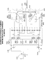
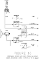
- the hydraulic schematic for one embodiment of the active tie-bar system is shown in FIG. 10 , which depicts hydraulic cylinder 1001 linking port drive 1014 and starboard drive 1015. The ends of hydraulic cylinder 1001 are fitted with port attachment (joint) 1016 and starboard attachment (joint) 1017.
- the hydraulic fluid in the locked state the hydraulic fluid is locked in the cylinder by means of counterbalance valves 1006, and the tie-bar arrangement behaves similar to a conventional tie-bar, whereby the port and starboard drives are maintained in a fixed relationship relative to each other.
- pressurized fluid is delivered by pump 1011 and/or 1013 to one side of the piston in cylinder 1001 via port steering valve 1008 and/or starboard steering valve 1009, as the case may be, while fluid on the other side of the piston is allowed to escape back to reservoir 1012.
- the hydraulic system shown in FIG. 10 is one example of how an electro-hydraulic control system could be adapted to integrate the use of an active electro-hydraulic tie-bar system.
- the working ports (A & B) of steering valves 1008 and 1009 are also connected to the Hydraulic-Actuator Tie-Bar (in addition to the steering actuators) through two dedicated sets of counterbalance valves 1006.
- the cylinder-side ports (A3 & B3 for STBD and A4 & B4 for PORT) of the dedicated tie-bar counterbalance valves are then ported to the tie-bar actuator such that actuating a single steering actuator (port or starboard) via the respective steering valve will also actuate the Hydraulic-Actuator Tie-Bar in the correct direction and not affect the steering actuator that is not being actuated.
- the circuit in FIG. 10 will also allow both steering valves and corresponding actuators to be actuated simultaneously.
- the circuit illustrated in FIG. 10 is one example of a hydraulic circuit designed to actuate the active tie-bar system. It is to be appreciated that various alterations, modifications, and improvements of the example shown in FIGS. 8 A-C and FIG.
- the active tie-bar may incorporate any device that can generate a suitable force, including but not limited to hydraulic cylinders, electrically-actuated power screws, pneumatic actuators, electromechanical devices, geared mechanisms, etc., and it is understood that any number of configurations within a given class of actuator may be adopted.
- Such alterations, modifications, and improvements are intended to be part of this disclosure and are intended to be within the scope of the system disclosed herein.
- One skilled in the art can modify the circuit in numerous ways, for example, by incorporating different types of valves and porting to perform the same function.
- FIG. 11 illustrates one embodiment of a system diagram for the device and embodiments thereof described herein.
- One system and method of implementing a joystick control algorithm for a dual-drive system is to separate the control algorithms into five separate control zones as shown in FIG. 12 , which are illustrated in more detail in FIGS. 13-17 .
- the difference in response characteristics of the steerable drive for example between ahead and reverse thrust, can be compensated for by applying a different set of curves for the respective zones.
- One embodiment of such a system splits the control algorithms into five different zones that relate to the direction of applied net translational thrust: Port Thrust, Starboard Thrust, Zero Thrust (rotation only), Ahead Thrust Only (i.e., no side or reverse thrust) and Astern Thrust Only, as shown in FIG. 12 .
- the underlying goal is to create a system that compensates for the discontinuities in the force and motion created by the combination of propulsion devices, including characteristics of transmission gear and associated trolling gear (if available), in response to command or actuator inputs, for example, by changing the steering position mapping to steering wheel inputs when transitioning from ahead thrust (Zone 4) to astern thrust (Zone 5).
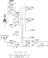
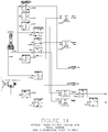
- FIGS. 13-17 contain example algorithms for Zones 1-5 respectively. Because the effects of the propeller thrust contribute to the net translation and rotational thrust in different ways depending on the direction of net translational thrust (zone), each zone has a dedicated algorithm such that the controller automatically updates the algorithm when transitioning from one zone to another.
- Each zone-specific algorithm contains a different mapping that relates the control devices (e.g., joystick and steering wheel) to the propulsion devices (e.g., steerable drive, transmission gear and associated trolling gear, engine RPM). For example, when thrusting ahead with no side thrust (Zone 4, FIG. 16 ), modules 1656 and 1657 turn the drives in the starboard direction when the helm is turned to starboard (CW). In contrast, when thrusting astern with no side thrust (Zone 5, Figure 17 ), modules 1750 and 1751 turn both drives to port when the helm is turned to starboard (CW).
- the control devices e.g., joystick and steering wheel
- propulsion devices e.g., steerable drive, transmission gear and associated trolling
- FIG. 5 A contains a maneuvering diagram (or Net Thrust Diagram) that illustrates a plurality of thrust forces for a plurality of controller conditions, that are provided to a vessel configured with the herein described embodiment of a system and that is equipped with two steerable drives.
- a maneuvering diagram or Net Thrust Diagram
- the resulting forces imparted to the vessel for a starboard turn when thrusting ahead is shown as maneuver C.
- maneuver O the resulting forces imparted to the vessel where the steering wheel is turned to starboard and while the craft is reversing.
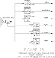
- FIG. 15 shows a signal diagram for Zone 3 of the herein described embodiment of a system. It is to be appreciated that since the condition for Zone 3 is zero translational thrust, the joystick inputs have been omitted from the diagram for simplification.
- FIG. 15 illustrates an effective method for developing rotational thrust with little or no translational thrust.
- maneuver F shown in FIG. 5 A
- the wheel is turned to starboard while the joystick is centered.
- Module 1541 FIG. 15
- module 1544 progressively increases the starboard gear setting to achieve progressively increasing propeller speed in the astern direction creating a force couple (moment) without creating a substantial net translational thrust.
- modules 1540 and 1543 progressively increase engine RPM once the wheel or tiller is moved beyond a threshold point.
- the system provides rotation forces with little or no translation forces by progressively pointing in the steerable propellers and/or applying a differential RPM to the drives as a function of wheel or tiller rotation.
- a differential RPM to the drives as a function of wheel or tiller rotation.
- the exact combination of trolling gear settings, steering angle movements, and engine RPM levels shown in the embodiment in FIG. 5 A is not required to achieve the same or similar results.
- the engine RPM can be increased at different points in the mapping or not at all with varying levels of effectiveness.
- the extent of toeing in the drives can be changed or eliminated, also with varying levels of effectiveness.
- Vessels equipped with steerable propellers are able to induce combinations of transverse and rotational thrusts that will allow the craft to translate sideways while at the same time apply varying amounts of rotational thrust.
- Zone 1 thrusting to port
- maneuver H an example maneuver in which a transverse thrust is applied to the craft without a rotational thrust.
- the required actuation of the trolling gear, steering angles and engine RPM to achieve maneuver H can be determined from the control diagram of FIG. 13 .
- maneuver H where the craft is translating sideways with little or no forward or reverse thrust.
- the initial condition is maneuver E (Zone 3), in which the joystick is centered (neutral X and neutral Y) and the steering wheel is centered; in this condition, both transmissions will be set to neutral, in accordance with the signals created by the joystick and transmitted to modules 1300 and 1303.
- the port drive steering angle is positioned (by module 1302 ) in a discrete position in the port direction and the starboard steering angle is positioned (by module 1305 ) in a discrete position in the starboard direction.
- the respective positions of the port and starboard drives correspond to the equilibrium point where translational thrust can be applied in any direction without inducing a substantial rotational or yawing force. These positions usually correspond to angles where both drives are pointed along respective center lines that intersect at or near the center of rotation of the craft. Drives that are positioned in this manner are sometimes referred to as being in a toe-out configuration. As long as the steering wheel remains in a neutral position that corresponds to no rotational thrust, both drives will remain in these respective discrete positions.
- progressively moving the joystick to increase the magnitude of net transverse thrust in the port direction will increase the trolling gear setting (increase in friction level) in the astern direction and increase the RPM of the port engine (not necessarily together), thereby increasing the reverse thrust of the port drive.
- moving the joystick to port will increase the trolling gear setting in the ahead direction and increase the RPM of the starboard engine, thereby increasing the ahead thrust of the starboard drive.
- the joystick is moved along the X-axis only (i.e., neutral Y position)
- the reversing thrust of the port drive and the ahead thrust of the starboard drive will remain substantially equal in magnitude so as to induce a net transverse thrust without imparting a net forward or reverse thrust.
- Adding a rotational thrust in the port or counter-clockwise direction is achieved by rotating the steering wheel in the counter-clockwise direction.
- moving the steering wheel to port CCW
- CCW moving the steering wheel to port
- This is achieved by creating an additional starboard movement with module 1310 for the port drive based on the magnitude of the wheel rotation and adding it to the discrete position output from module 1302 at summing module 1316.
- an additional port movement is added to the starboard drive by module 1311 and summed with the discrete output of module 1305 at summing module 1317.
- module 1318 for the port drive So as not to create a situation where the drives are allowed to move to a point beyond the neutral position such that the direction of translational thrust differs substantially from the joystick movement, absolute limits are placed on the steering movements with module 1318 for the port drive and module 1319 for the starboard drive. Module 1318 will not allow the port drive to move to the starboard side of neutral (straight ahead) and module 1319 will not allow the starboard drive to move to the port side of neutral. It is to be appreciated, however, that for cases in which there is not enough rotational thrust available in one direction as provided by the system described herein, the limits set by modules 1318 and 1319 can be extended.
- the magnitude of the steering angles of the port and starboard drives in response to steering wheel movements need not be the same, provided there are minimal changes in translational thrust resulting from movements of the steering wheel or tiller.
- the optimum amounts of steering angle movement for each drive in response to steering commands depends heavily on the hydrodynamics of the craft during side thrusting operations as well as the hull-propeller interactions for each drive. These points can be estimated with application-specific modeling or determined during a sea trial.
- Zone 2 of FIG. 5 A is substantially a mirror image of Zone 1, and therefore the corresponding modules of FIG. 14 and the resulting maneuvers J, K and L illustrated in FIG. 5 A will not be discussed in detail here, for the sake of brevity.
- Zones 1 and 2 cover all movements of the joystick to the respective side of neutral (with respect to transverse thrust).
- the control algorithms described in FIG. 13 for Zone 1 and FIG. 14 for Zone 2 also are configured to add varying levels of ahead and astern thrust in response to joystick movements along the Y axis in order to respond to diagonal translational thrust commands from the joystick.
- FIG. 5 B which illustrates movements of a vessel configured with the control system of one embodiment of the invention and equipped with dual steerable propellers
- maneuver Q can be achieved by maintaining the steering wheel at a neutral position such that modules 1310 and 1311 (of FIG.
- module 1306 of FIG. 13 progressively decreases the port engine RPM and module 1308 progressively increases the starboard engine RPM, thereby decreasing the astern thrust of the port drive and increasing the ahead thrust of the starboard drive.
- This maneuver is illustrated as maneuver Q in FIG. 5 B , by schematically indicating the reduction of thrust in the port drive and the increase in thrust of the starboard drive.
- a rotational thrust to port (CCW) can be added by turning the wheel counter clockwise, thereby moving the drives towards the center as shown in maneuver P of FIG. 5 B .
- a clockwise rotational thrust can be achieved by turning the wheel to starboard which will move the drives away from the center, as shown in maneuver R ( FIG. 5 B ).
- reverse diagonal thrust can be developed by moving the joystick backward along the Y axis.
- module 1306 increases the astern thrust of the port drive and module 1308 decreases the ahead thrust of the starboard drive.
- This diagonal backwards and to port maneuver is illustrated as maneuver T of FIG. 5 B .
- a rotational thrust to port (CCW) can be added by turning the wheel counter clockwise, thereby moving the drives towards the center as shown in maneuver S of FIG. 5 B .
- a clockwise rotational thrust can be achieved by turning the wheel to starboard which will move the drives away from the center (i.e., drives splayed), as shown in maneuver U of FIG. 5 B .
- Zone 2 of FIG. 5 A is substantially a mirror image of Zone 1, and therefore the corresponding modules of FIG. 14 will not be discussed in detail here for the sake of brevity.
- summation modules herein described and illustrated can sum the various signals in different ways. For example, different signals may have different weights in the summation or selected signals may be left out of the summation under certain conditions. It is also the function of the summation module to clamp (limit) output signals that would otherwise exceed maximum values.
- port trolling gear module illustrated in FIGS. 13-17 can be separated into two distinct modules to handle direction and friction level, respectively, for the port transmission. It is understood that the foregoing statement applies to the starboard trolling gear module.
Landscapes
- Chemical & Material Sciences (AREA)
- Engineering & Computer Science (AREA)
- Combustion & Propulsion (AREA)
- Mechanical Engineering (AREA)
- Ocean & Marine Engineering (AREA)
- Mechanical Control Devices (AREA)
- Other Liquid Machine Or Engine Such As Wave Power Use (AREA)
- Fluid-Pressure Circuits (AREA)
Claims (7)
- Vorrichtung für ein Wasserfahrzeug mit einem ersten (1014) und einem zweiten (1015) Antrieb, wobei die Vorrichtung ein elektrohydraulisches Steuersystem umfasst, wobei das genannte System Folgendes umfasst:einen Holmstellantrieb (1001);einen Lenkstellantrieb (1002, 1005), der jeweils für den ersten und den zweiten Antrieb des Wasserfahrzeugs vorgesehen ist; undein jeweiliges Lenkventil (1008, 1009), das für jeden Lenkstellantrieb (1002, 1005) vorgesehen ist,wobei das genannte elektrohydraulische Steuersystem zum Steuern des Holmstellantriebs (1001) konfiguriert ist, um eine Kraft zwischen dem ersten Antrieb (1014) und dem zweiten Antrieb (1015) des Wasserfahrzeugs zu erzeugen,wobei das Stellen des einzelnen Lenkstellantriebs (1002, 1005) auf Backbord oder Steuerbord über das jeweilige Lenkventil (1008, 1009) auch den Holmstellantrieb (1001) stellt.
- Vorrichtung nach Anspruch 1, wobei der Holmstellantrieb (1001) einen hydraulischen Stellantrieb umfasst.
- Vorrichtung nach Anspruch 1, wobei der Holmstellantrieb (1001) einen Hydraulikzylinder, eine elektrisch betätigte Antriebsschraube, einen pneumatischen Stellantrieb, eine elektromechanische Vorrichtung oder einen Getriebemechanismus umfasst.
- Vorrichtung nach Anspruch 1, wobei die Steuereinheit einen Hydraulikkreis mit dem ersten Lenkventil (1008) und dem zweiten Lenkventil (1009) umfasst und wobei beide Lenkventile (1008, 1009) gleichzeitig gestellt werden können.
- Vorrichtung nach Anspruch 4, wobei Arbeitsanschlüsse (A, B) der Lenkventile (1008, 1009) durch zwei dedizierte Sätze von Gegenausgleichsventilen (1006) mit dem Holmstellantrieb (1001) verbunden sind.
- Vorrichtung nach Anspruch 5, wobei zylinderseitige Anschlüsse (A3 & B3 für STBD und A4 & B4 für BKBD) der dedizierten Holmgegenausgleichsventile (1006) an den Holmstellantrieb (1001) angeschlossen sind.
- Vorrichtung nach Anspruch 6, wobei das Stellen des einzelnen Lenkstellantriebs (1002, 1005) und des Holmstellantriebs (1101) keinen anderen Lenkstellantrieb (1002, 1005) beeinflusst, der nicht gestellt wird.
Applications Claiming Priority (3)
| Application Number | Priority Date | Filing Date | Title |
|---|---|---|---|
| US38552610P | 2010-09-22 | 2010-09-22 | |
| US201161453936P | 2011-03-17 | 2011-03-17 | |
| PCT/US2011/052851 WO2012040521A1 (en) | 2010-09-22 | 2011-09-22 | System for controlling marine craft with twin steerable propellers |
Publications (2)
| Publication Number | Publication Date |
|---|---|
| EP2619082A1 EP2619082A1 (de) | 2013-07-31 |
| EP2619082B1 true EP2619082B1 (de) | 2020-11-04 |
Family
ID=44789597
Family Applications (1)
| Application Number | Title | Priority Date | Filing Date |
|---|---|---|---|
| EP11768206.2A Active EP2619082B1 (de) | 2010-09-22 | 2011-09-22 | System zur steuerung eines wasserfahrzeugs mit lenkbaren doppelpropellern |
Country Status (3)
| Country | Link |
|---|---|
| US (7) | US9340271B2 (de) |
| EP (1) | EP2619082B1 (de) |
| WO (1) | WO2012040521A1 (de) |
Families Citing this family (11)
| Publication number | Priority date | Publication date | Assignee | Title |
|---|---|---|---|---|
| WO2012040521A1 (en) * | 2010-09-22 | 2012-03-29 | Morvillo Robert A | System for controlling marine craft with twin steerable propellers |
| JP5987624B2 (ja) * | 2012-10-11 | 2016-09-07 | スズキ株式会社 | 船外機の制御装置、船外機の制御方法およびプログラム |
| US9932098B1 (en) * | 2015-09-02 | 2018-04-03 | Brunswick Corporation | Systems and methods for continuously adapting a toe angle between marine propulsion devices |
| CN107161309B (zh) * | 2016-01-18 | 2019-02-22 | 山东大学 | 一种偏转型矢量推进器及水下航行器 |
| US9896174B1 (en) * | 2016-08-22 | 2018-02-20 | Brunswick Corporation | System and method for controlling trim position of propulsion device on a marine vessel |
| US10011339B2 (en) | 2016-08-22 | 2018-07-03 | Brunswick Corporation | System and method for controlling trim position of propulsion devices on a marine vessel |
| US10118682B2 (en) | 2016-08-22 | 2018-11-06 | Brunswick Corporation | Method and system for controlling trim position of a propulsion device on a marine vessel |
| US11198494B2 (en) * | 2018-11-01 | 2021-12-14 | Brunswick Corporation | Methods and systems for controlling propulsion of a marine vessel to enhance proximity sensing in a marine environment |
| US12600449B1 (en) | 2023-05-10 | 2026-04-14 | Brunswick Corporation | Marine vessels having a first marine drive and a second marine drive and methods for controlling them |
| JP7440136B1 (ja) * | 2023-01-25 | 2024-02-28 | 株式会社鷹取製作所 | 船舶の操縦支援装置 |
| CN116873173B (zh) * | 2023-06-14 | 2026-02-10 | 浙江大学 | 一种用于跨域航行器的矢量动力推进系统及控制方法 |
Citations (1)
| Publication number | Priority date | Publication date | Assignee | Title |
|---|---|---|---|---|
| US7467595B1 (en) * | 2007-01-17 | 2008-12-23 | Brunswick Corporation | Joystick method for maneuvering a marine vessel with two or more sterndrive units |
Family Cites Families (21)
| Publication number | Priority date | Publication date | Assignee | Title |
|---|---|---|---|---|
| US2999476A (en) * | 1958-09-26 | 1961-09-12 | Johnson George Verne | Outboard marine drive for inboard engine |
| US2968192A (en) * | 1959-09-02 | 1961-01-17 | Albert C Fletcher | Coupling device for twin outboard motors |
| US3756186A (en) * | 1971-04-30 | 1973-09-04 | H Nordling | Attachment for connecting a stern drive unit and an auxiliary outboard motor |
| US4778418A (en) * | 1987-08-31 | 1988-10-18 | Outboard Marine Corporation | Tie bar for marine propulsion devices |
| US6179673B1 (en) * | 2000-03-01 | 2001-01-30 | Raymond A. Leroux | Outboard motor protection apparatus |
| US6561860B2 (en) * | 2000-10-18 | 2003-05-13 | Constantine N. Colyvas | Maneuvering enhancer for twin outboard motor boats |
| US7037150B2 (en) | 2001-09-28 | 2006-05-02 | Morvillo Robert A | Method and apparatus for controlling a waterjet-driven marine vessel |
| US7052338B2 (en) | 2001-08-06 | 2006-05-30 | Morvillo Robert A | Integral reversing and trim deflector and control mechanism |
| US7222577B2 (en) | 2001-09-28 | 2007-05-29 | Robert A. Morvillo | Method and apparatus for controlling a waterjet-driven marine vessel |
| US6699082B2 (en) * | 2002-07-03 | 2004-03-02 | Donald J. Zeiger | Tie bar and mount for boat drives |
| ITSV20040029A1 (it) | 2004-06-29 | 2004-09-29 | Ultraflex Spa | Dispositivo idraulico di sterzatura per motori marini |
| NZ555164A (en) | 2004-11-24 | 2010-12-24 | Robert A Morvillo | System and method for controlling a waterjet driven vessel |
| US7128626B2 (en) * | 2005-01-12 | 2006-10-31 | Teleflex Canada Incorporated | Marine steering assembly with connecting member |
| JP4628915B2 (ja) * | 2005-09-22 | 2011-02-09 | 本田技研工業株式会社 | 船外機の操舵装置 |
| JP4673187B2 (ja) | 2005-10-25 | 2011-04-20 | ヤマハ発動機株式会社 | 多機掛け推進機の制御装置 |
| JP4732860B2 (ja) * | 2005-11-04 | 2011-07-27 | ヤマハ発動機株式会社 | 船外機用電動式操舵装置 |
| WO2007067599A1 (en) | 2005-12-05 | 2007-06-14 | Morvillo Robert A | Method and apparatus for controlling a marine vessel |
| US7267588B1 (en) * | 2006-03-01 | 2007-09-11 | Brunswick Corporation | Selectively lockable marine propulsion devices |
| US8126602B2 (en) | 2006-12-19 | 2012-02-28 | Morvillo Robert A | Method and apparatus for controlling a water-jet driven marine vessel |
| WO2010115064A2 (en) | 2009-04-01 | 2010-10-07 | Morvillo Robert A | Ventilation control system |
| WO2012040521A1 (en) * | 2010-09-22 | 2012-03-29 | Morvillo Robert A | System for controlling marine craft with twin steerable propellers |
-
2011
- 2011-09-22 WO PCT/US2011/052851 patent/WO2012040521A1/en not_active Ceased
- 2011-09-22 US US13/241,192 patent/US9340271B2/en active Active
- 2011-09-22 EP EP11768206.2A patent/EP2619082B1/de active Active
-
2016
- 2016-04-14 US US15/099,334 patent/US20170015399A1/en not_active Abandoned
-
2018
- 2018-03-12 US US15/918,126 patent/US20180334235A1/en not_active Abandoned
-
2020
- 2020-01-31 US US16/778,160 patent/US20200361588A1/en not_active Abandoned
-
2021
- 2021-09-17 US US17/478,242 patent/US20220212769A1/en not_active Abandoned
-
2023
- 2023-07-11 US US18/350,038 patent/US20240166325A1/en not_active Abandoned
-
2024
- 2024-08-29 US US18/819,290 patent/US20250229885A1/en active Pending
Patent Citations (1)
| Publication number | Priority date | Publication date | Assignee | Title |
|---|---|---|---|---|
| US7467595B1 (en) * | 2007-01-17 | 2008-12-23 | Brunswick Corporation | Joystick method for maneuvering a marine vessel with two or more sterndrive units |
Also Published As
| Publication number | Publication date |
|---|---|
| US9340271B2 (en) | 2016-05-17 |
| US20170015399A1 (en) | 2017-01-19 |
| US20240166325A1 (en) | 2024-05-23 |
| US20180334235A1 (en) | 2018-11-22 |
| WO2012040521A1 (en) | 2012-03-29 |
| EP2619082A1 (de) | 2013-07-31 |
| US20250229885A1 (en) | 2025-07-17 |
| US20220212769A1 (en) | 2022-07-07 |
| US20200361588A1 (en) | 2020-11-19 |
| US20120135649A1 (en) | 2012-05-31 |
Similar Documents
| Publication | Publication Date | Title |
|---|---|---|
| US20250229885A1 (en) | System for controlling marine craft with steerable propellers | |
| US11845524B2 (en) | System for controlling marine craft with steerable drives | |
| US20250368302A1 (en) | Variable trim deflector system and method for controlling a marine vessel | |
| US20250058865A1 (en) | Method and apparatus for controlling a marine vessel | |
| US20240109630A1 (en) | System and method for controlling a marine vessel | |
| US9233740B2 (en) | Variable trim deflector system with protruding foil and method for controlling a marine vessel | |
| US7052338B2 (en) | Integral reversing and trim deflector and control mechanism | |
| JP3958051B2 (ja) | 船舶およびその運用方法 | |
| US20110086560A1 (en) | Steering Control Arrangement for Boats | |
| JP4119934B2 (ja) | 船舶及び船舶の運用方法 |
Legal Events
| Date | Code | Title | Description |
|---|---|---|---|
| PUAI | Public reference made under article 153(3) epc to a published international application that has entered the european phase |
Free format text: ORIGINAL CODE: 0009012 |
|
| 17P | Request for examination filed |
Effective date: 20130418 |
|
| AK | Designated contracting states |
Kind code of ref document: A1 Designated state(s): AL AT BE BG CH CY CZ DE DK EE ES FI FR GB GR HR HU IE IS IT LI LT LU LV MC MK MT NL NO PL PT RO RS SE SI SK SM TR |
|
| DAX | Request for extension of the european patent (deleted) | ||
| STAA | Information on the status of an ep patent application or granted ep patent |
Free format text: STATUS: EXAMINATION IS IN PROGRESS |
|
| 17Q | First examination report despatched |
Effective date: 20171107 |
|
| GRAP | Despatch of communication of intention to grant a patent |
Free format text: ORIGINAL CODE: EPIDOSNIGR1 |
|
| STAA | Information on the status of an ep patent application or granted ep patent |
Free format text: STATUS: GRANT OF PATENT IS INTENDED |
|
| RIC1 | Information provided on ipc code assigned before grant |
Ipc: B63H 20/00 20060101ALN20200429BHEP Ipc: B63H 20/12 20060101ALI20200429BHEP Ipc: B63H 21/21 20060101ALI20200429BHEP Ipc: B63H 25/42 20060101AFI20200429BHEP |
|
| INTG | Intention to grant announced |
Effective date: 20200513 |
|
| GRAS | Grant fee paid |
Free format text: ORIGINAL CODE: EPIDOSNIGR3 |
|
| GRAA | (expected) grant |
Free format text: ORIGINAL CODE: 0009210 |
|
| STAA | Information on the status of an ep patent application or granted ep patent |
Free format text: STATUS: THE PATENT HAS BEEN GRANTED |
|
| AK | Designated contracting states |
Kind code of ref document: B1 Designated state(s): AL AT BE BG CH CY CZ DE DK EE ES FI FR GB GR HR HU IE IS IT LI LT LU LV MC MK MT NL NO PL PT RO RS SE SI SK SM TR |
|
| REG | Reference to a national code |
Ref country code: GB Ref legal event code: FG4D |
|
| REG | Reference to a national code |
Ref country code: CH Ref legal event code: EP |
|
| REG | Reference to a national code |
Ref country code: AT Ref legal event code: REF Ref document number: 1330502 Country of ref document: AT Kind code of ref document: T Effective date: 20201115 |
|
| REG | Reference to a national code |
Ref country code: IE Ref legal event code: FG4D |
|
| REG | Reference to a national code |
Ref country code: DE Ref legal event code: R096 Ref document number: 602011069172 Country of ref document: DE |
|
| REG | Reference to a national code |
Ref country code: NL Ref legal event code: MP Effective date: 20201104 |
|
| REG | Reference to a national code |
Ref country code: AT Ref legal event code: MK05 Ref document number: 1330502 Country of ref document: AT Kind code of ref document: T Effective date: 20201104 |
|
| PG25 | Lapsed in a contracting state [announced via postgrant information from national office to epo] |
Ref country code: GR Free format text: LAPSE BECAUSE OF FAILURE TO SUBMIT A TRANSLATION OF THE DESCRIPTION OR TO PAY THE FEE WITHIN THE PRESCRIBED TIME-LIMIT Effective date: 20210205 Ref country code: RS Free format text: LAPSE BECAUSE OF FAILURE TO SUBMIT A TRANSLATION OF THE DESCRIPTION OR TO PAY THE FEE WITHIN THE PRESCRIBED TIME-LIMIT Effective date: 20201104 Ref country code: FI Free format text: LAPSE BECAUSE OF FAILURE TO SUBMIT A TRANSLATION OF THE DESCRIPTION OR TO PAY THE FEE WITHIN THE PRESCRIBED TIME-LIMIT Effective date: 20201104 Ref country code: NO Free format text: LAPSE BECAUSE OF FAILURE TO SUBMIT A TRANSLATION OF THE DESCRIPTION OR TO PAY THE FEE WITHIN THE PRESCRIBED TIME-LIMIT Effective date: 20210204 Ref country code: PT Free format text: LAPSE BECAUSE OF FAILURE TO SUBMIT A TRANSLATION OF THE DESCRIPTION OR TO PAY THE FEE WITHIN THE PRESCRIBED TIME-LIMIT Effective date: 20210304 |
|
| PG25 | Lapsed in a contracting state [announced via postgrant information from national office to epo] |
Ref country code: LV Free format text: LAPSE BECAUSE OF FAILURE TO SUBMIT A TRANSLATION OF THE DESCRIPTION OR TO PAY THE FEE WITHIN THE PRESCRIBED TIME-LIMIT Effective date: 20201104 Ref country code: PL Free format text: LAPSE BECAUSE OF FAILURE TO SUBMIT A TRANSLATION OF THE DESCRIPTION OR TO PAY THE FEE WITHIN THE PRESCRIBED TIME-LIMIT Effective date: 20201104 Ref country code: SE Free format text: LAPSE BECAUSE OF FAILURE TO SUBMIT A TRANSLATION OF THE DESCRIPTION OR TO PAY THE FEE WITHIN THE PRESCRIBED TIME-LIMIT Effective date: 20201104 Ref country code: IS Free format text: LAPSE BECAUSE OF FAILURE TO SUBMIT A TRANSLATION OF THE DESCRIPTION OR TO PAY THE FEE WITHIN THE PRESCRIBED TIME-LIMIT Effective date: 20210304 Ref country code: ES Free format text: LAPSE BECAUSE OF FAILURE TO SUBMIT A TRANSLATION OF THE DESCRIPTION OR TO PAY THE FEE WITHIN THE PRESCRIBED TIME-LIMIT Effective date: 20201104 Ref country code: AT Free format text: LAPSE BECAUSE OF FAILURE TO SUBMIT A TRANSLATION OF THE DESCRIPTION OR TO PAY THE FEE WITHIN THE PRESCRIBED TIME-LIMIT Effective date: 20201104 Ref country code: BG Free format text: LAPSE BECAUSE OF FAILURE TO SUBMIT A TRANSLATION OF THE DESCRIPTION OR TO PAY THE FEE WITHIN THE PRESCRIBED TIME-LIMIT Effective date: 20210204 |
|
| REG | Reference to a national code |
Ref country code: LT Ref legal event code: MG9D |
|
| PG25 | Lapsed in a contracting state [announced via postgrant information from national office to epo] |
Ref country code: HR Free format text: LAPSE BECAUSE OF FAILURE TO SUBMIT A TRANSLATION OF THE DESCRIPTION OR TO PAY THE FEE WITHIN THE PRESCRIBED TIME-LIMIT Effective date: 20201104 |
|
| PG25 | Lapsed in a contracting state [announced via postgrant information from national office to epo] |
Ref country code: LT Free format text: LAPSE BECAUSE OF FAILURE TO SUBMIT A TRANSLATION OF THE DESCRIPTION OR TO PAY THE FEE WITHIN THE PRESCRIBED TIME-LIMIT Effective date: 20201104 Ref country code: RO Free format text: LAPSE BECAUSE OF FAILURE TO SUBMIT A TRANSLATION OF THE DESCRIPTION OR TO PAY THE FEE WITHIN THE PRESCRIBED TIME-LIMIT Effective date: 20201104 Ref country code: SK Free format text: LAPSE BECAUSE OF FAILURE TO SUBMIT A TRANSLATION OF THE DESCRIPTION OR TO PAY THE FEE WITHIN THE PRESCRIBED TIME-LIMIT Effective date: 20201104 Ref country code: SM Free format text: LAPSE BECAUSE OF FAILURE TO SUBMIT A TRANSLATION OF THE DESCRIPTION OR TO PAY THE FEE WITHIN THE PRESCRIBED TIME-LIMIT Effective date: 20201104 Ref country code: CZ Free format text: LAPSE BECAUSE OF FAILURE TO SUBMIT A TRANSLATION OF THE DESCRIPTION OR TO PAY THE FEE WITHIN THE PRESCRIBED TIME-LIMIT Effective date: 20201104 Ref country code: EE Free format text: LAPSE BECAUSE OF FAILURE TO SUBMIT A TRANSLATION OF THE DESCRIPTION OR TO PAY THE FEE WITHIN THE PRESCRIBED TIME-LIMIT Effective date: 20201104 |
|
| REG | Reference to a national code |
Ref country code: DE Ref legal event code: R097 Ref document number: 602011069172 Country of ref document: DE |
|
| PG25 | Lapsed in a contracting state [announced via postgrant information from national office to epo] |
Ref country code: DK Free format text: LAPSE BECAUSE OF FAILURE TO SUBMIT A TRANSLATION OF THE DESCRIPTION OR TO PAY THE FEE WITHIN THE PRESCRIBED TIME-LIMIT Effective date: 20201104 |
|
| PLBE | No opposition filed within time limit |
Free format text: ORIGINAL CODE: 0009261 |
|
| STAA | Information on the status of an ep patent application or granted ep patent |
Free format text: STATUS: NO OPPOSITION FILED WITHIN TIME LIMIT |
|
| 26N | No opposition filed |
Effective date: 20210805 |
|
| PG25 | Lapsed in a contracting state [announced via postgrant information from national office to epo] |
Ref country code: AL Free format text: LAPSE BECAUSE OF FAILURE TO SUBMIT A TRANSLATION OF THE DESCRIPTION OR TO PAY THE FEE WITHIN THE PRESCRIBED TIME-LIMIT Effective date: 20201104 Ref country code: NL Free format text: LAPSE BECAUSE OF FAILURE TO SUBMIT A TRANSLATION OF THE DESCRIPTION OR TO PAY THE FEE WITHIN THE PRESCRIBED TIME-LIMIT Effective date: 20201104 |
|
| PG25 | Lapsed in a contracting state [announced via postgrant information from national office to epo] |
Ref country code: SI Free format text: LAPSE BECAUSE OF FAILURE TO SUBMIT A TRANSLATION OF THE DESCRIPTION OR TO PAY THE FEE WITHIN THE PRESCRIBED TIME-LIMIT Effective date: 20201104 |
|
| REG | Reference to a national code |
Ref country code: CH Ref legal event code: PL |
|
| REG | Reference to a national code |
Ref country code: BE Ref legal event code: MM Effective date: 20210930 |
|
| PG25 | Lapsed in a contracting state [announced via postgrant information from national office to epo] |
Ref country code: IS Free format text: LAPSE BECAUSE OF FAILURE TO SUBMIT A TRANSLATION OF THE DESCRIPTION OR TO PAY THE FEE WITHIN THE PRESCRIBED TIME-LIMIT Effective date: 20210304 Ref country code: MC Free format text: LAPSE BECAUSE OF FAILURE TO SUBMIT A TRANSLATION OF THE DESCRIPTION OR TO PAY THE FEE WITHIN THE PRESCRIBED TIME-LIMIT Effective date: 20201104 |
|
| PG25 | Lapsed in a contracting state [announced via postgrant information from national office to epo] |
Ref country code: LU Free format text: LAPSE BECAUSE OF NON-PAYMENT OF DUE FEES Effective date: 20210922 Ref country code: IE Free format text: LAPSE BECAUSE OF NON-PAYMENT OF DUE FEES Effective date: 20210922 Ref country code: BE Free format text: LAPSE BECAUSE OF NON-PAYMENT OF DUE FEES Effective date: 20210930 |
|
| PG25 | Lapsed in a contracting state [announced via postgrant information from national office to epo] |
Ref country code: LI Free format text: LAPSE BECAUSE OF NON-PAYMENT OF DUE FEES Effective date: 20210930 Ref country code: CH Free format text: LAPSE BECAUSE OF NON-PAYMENT OF DUE FEES Effective date: 20210930 |
|
| PG25 | Lapsed in a contracting state [announced via postgrant information from national office to epo] |
Ref country code: HU Free format text: LAPSE BECAUSE OF FAILURE TO SUBMIT A TRANSLATION OF THE DESCRIPTION OR TO PAY THE FEE WITHIN THE PRESCRIBED TIME-LIMIT; INVALID AB INITIO Effective date: 20110922 Ref country code: CY Free format text: LAPSE BECAUSE OF FAILURE TO SUBMIT A TRANSLATION OF THE DESCRIPTION OR TO PAY THE FEE WITHIN THE PRESCRIBED TIME-LIMIT Effective date: 20201104 |
|
| P01 | Opt-out of the competence of the unified patent court (upc) registered |
Effective date: 20230524 |
|
| PG25 | Lapsed in a contracting state [announced via postgrant information from national office to epo] |
Ref country code: MK Free format text: LAPSE BECAUSE OF FAILURE TO SUBMIT A TRANSLATION OF THE DESCRIPTION OR TO PAY THE FEE WITHIN THE PRESCRIBED TIME-LIMIT Effective date: 20201104 |
|
| PG25 | Lapsed in a contracting state [announced via postgrant information from national office to epo] |
Ref country code: TR Free format text: LAPSE BECAUSE OF FAILURE TO SUBMIT A TRANSLATION OF THE DESCRIPTION OR TO PAY THE FEE WITHIN THE PRESCRIBED TIME-LIMIT Effective date: 20201104 |
|
| PG25 | Lapsed in a contracting state [announced via postgrant information from national office to epo] |
Ref country code: MT Free format text: LAPSE BECAUSE OF FAILURE TO SUBMIT A TRANSLATION OF THE DESCRIPTION OR TO PAY THE FEE WITHIN THE PRESCRIBED TIME-LIMIT Effective date: 20201104 |
|
| PGFP | Annual fee paid to national office [announced via postgrant information from national office to epo] |
Ref country code: GB Payment date: 20260127 Year of fee payment: 15 |
|
| PGFP | Annual fee paid to national office [announced via postgrant information from national office to epo] |
Ref country code: DE Payment date: 20260128 Year of fee payment: 15 |
|
| PGFP | Annual fee paid to national office [announced via postgrant information from national office to epo] |
Ref country code: IT Payment date: 20260219 Year of fee payment: 15 |
|
| PGFP | Annual fee paid to national office [announced via postgrant information from national office to epo] |
Ref country code: FR Payment date: 20260126 Year of fee payment: 15 |