EP2618340A1 - Method for impregnating an insulating material applied to a conductor with a resin - Google Patents
Method for impregnating an insulating material applied to a conductor with a resin Download PDFInfo
- Publication number
- EP2618340A1 EP2618340A1 EP12151940.9A EP12151940A EP2618340A1 EP 2618340 A1 EP2618340 A1 EP 2618340A1 EP 12151940 A EP12151940 A EP 12151940A EP 2618340 A1 EP2618340 A1 EP 2618340A1
- Authority
- EP
- European Patent Office
- Prior art keywords
- conductor
- resin
- magnetic field
- insulating material
- strands
- Prior art date
- Legal status (The legal status is an assumption and is not a legal conclusion. Google has not performed a legal analysis and makes no representation as to the accuracy of the status listed.)
- Withdrawn
Links
Images



Classifications
-
- H—ELECTRICITY
- H01—ELECTRIC ELEMENTS
- H01B—CABLES; CONDUCTORS; INSULATORS; SELECTION OF MATERIALS FOR THEIR CONDUCTIVE, INSULATING OR DIELECTRIC PROPERTIES
- H01B19/00—Apparatus or processes specially adapted for manufacturing insulators or insulating bodies
- H01B19/04—Treating the surfaces, e.g. applying coatings
-
- H—ELECTRICITY
- H01—ELECTRIC ELEMENTS
- H01B—CABLES; CONDUCTORS; INSULATORS; SELECTION OF MATERIALS FOR THEIR CONDUCTIVE, INSULATING OR DIELECTRIC PROPERTIES
- H01B13/00—Apparatus or processes specially adapted for manufacturing conductors or cables
- H01B13/06—Insulating conductors or cables
- H01B13/065—Insulating conductors with lacquers or enamels
-
- H—ELECTRICITY
- H02—GENERATION; CONVERSION OR DISTRIBUTION OF ELECTRIC POWER
- H02K—DYNAMO-ELECTRIC MACHINES
- H02K15/00—Processes or apparatus specially adapted for manufacturing, assembling, maintaining or repairing of dynamo-electric machines
- H02K15/12—Impregnating, moulding insulation, heating or drying of windings, stators, rotors or machines
- H02K15/125—Heating or drying of machines in operational state, e.g. standstill heating
Definitions
- the present disclosure relates to a method for impregnating an insulating material applied to a conductor.
- the method can be used during manufacturing of insulated conductors to be used in rotating electric machines such as electric generators or electric motors (stator bars). It is anyhow clear that the method can be used to manufacture any other kind of insulated conductors.
- the conductor is a transposed conductor, i.e. it includes a plurality of strands slightly insulated from one another with insulating material (for example fiber-glass) applied to each of the strands; during manufacturing also this insulating material has to be impregnated with the resin that is then cured; this way an internal insulation is manufactured.
- insulating material for example fiber-glass
- Impregnation should be from one side fast, because the resin properties degrade over time, and from another side it should be slow, to allow a proper impregnation of the insulating material.
- An aspect of the disclosure includes providing a method by which impregnation is improved.
- Another aspect of the disclosure includes providing a method that allows a fast impregnation but avoids or limits the drawbacks of the impregnation speed.
- an insulated conductor 1 such as a stator bar
- a conductor 2 and an insulating material 3 applied to the conductor 2 are provided.
- the conductor 2 can be a solid conductor, such as a copper bar made in one element, or a transposed conductor, such as a conductor made of a plurality of transposed strands 4 (for example copper strands) insulated with an insulating material 5 from one another.
- the insulating material 3 can be a mica tape wrapped around the conductor 2 in one or more layers and the insulating material 5 can be a fiber-glass that covers each strand 4 in one or more layers.
- an envelope 6 is provided around the conductor 2 wrapped with the insulation 3, and a vacuum is made in the envelope 6.
- a vacuum pump 7 can be provided, to reach an under pressure inside of the envelope 6.
- the resin can be injected into the envelope 6 (reference 9 indicates the injected resin); in this case the resin can be injected at high or low pressure, or it can be sucked (vacuum). It is anyhow clear that injection can occur at any pressure that allows injection and impregnation.
- the resin can be included in the insulating material 3 (that is applied to the conductor 2) and/or to the insulating material 5 (that is applied to the strands 4); reference 10 indicates the resin (for example a B stage resin) included in the insulating material 3 and/or 5.
- reference 10 indicates the resin (for example a B stage resin) included in the insulating material 3 and/or 5.
- tapes known as Resin Rich tapes can be used; these tapes have a mica layer bounded to a resin layer, such that during impregnation the resin layer melts and impregnates the mica layer.
- the resin After impregnation the resin is cured (reference 11 indicated heat) to realise the insulation and the insulated bar 1.
- the conductor 2 is supplied with an intermittent current 12 (pulse current), for the intermittent current 12 to generate an intermittent magnetic field.
- intermittent current 12 pulse current
- each strand 4 when the conductor 2 comprises a plurality of transposed strands 4, each strand 4 generates a magnetic field when the current 12 passes through it, but the magnetic field is extinguished when no current passes through the strands anymore.
- the magnetic fields causes forces between the strands that in turn generate displacements 13 of the strands.
- switch-on of the current can cause strands mutual attraction and switch-off can let the strands bounce back to their original positions.
- the current 12 is an intermittent current and thus the displacements 13 are also intermittent displacements, the strands 4 and conductors 2 start to vibrate.
- This vibration improves impregnation of both insulating materials 3 and 5, because the friction reduction by vibration proved to be an effective method to enhance the flowing of viscous fluids, like epoxy resins that is usually used to impregnate the insulating material 3, 5.
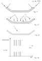
- figure 14 shows the relationship between the intermittent current and the displacement of the strands 4.
- the conductor 2 can also be immersed in an external magnetic field.
- the flexibility can be improved, because the external magnetic field can have the same or opposite polarity as the magnetic field generated by the strands 4 (i.e. by the conductor 2) or is can be extinguished. Naturally, the same effect can be achieved by changing the current of the current 12 (to change the polarity of the magnetic field of the conductor 2 and/or strands 4).
- reference 14 indicates the displacement generated by the interaction with the external magnetic field.
- figure 15 shows an example of the relationship between the intermittent current, the displacement of the strands 4 and/or conductor 2 and the external magnetic field.
- the conductor 2 can also at least partially face one or more ferromagnetic elements 15.
- the effect is the one already described before, because the ferromagnetic element generates attraction between the strands 4 (and thus conductor 2) and the ferromagnetic material 15 itself when the intermittent current 12 passes through the conductor 2, and no attraction when no intermittent current 12 passes through the conductor 2.
- the amplitude and/or frequency and/or shape (waveform) of the intermittent current 12 is preferably regulated; this lets the vibration of the strands 4 and conductor 2 be regulated.
- the intermittent current 12 can be regulated such that it has a frequency corresponding to a resonance frequency for the conductor 2 or at least a strand 4.
- the resonance frequency need not necessarily be the first resonance frequency, but is can also be a subsequent resonance frequency to improve impregnation of specific parts of the conductor 2 and/or strands 4.
- the resonance frequency of the conductor 2 and/or bars 4 can vary over time, for example because of changes in working conditions.
- a steady-matched resonance technique can be used.
- the steady matched resonance technique allows a matching of the current 12 with the resonance frequencies by feedback of signals; this allows a reduction of the dissipation (excessive heat generation in the conductors) and an increase of the vibration amplitude.
- the external magnetic field and/or the magnetic field generated by the conductor 2 can have a variable polarity and/or amplitude over the conductor length and/or over time. This can help impregnation because it allows large flexibility of the intensity and application zones of the forces applied to the conductor 2.
- the external magnetic field is preferably generated by at least a magnet 16; in different examples:
- the magnet or magnets 16 can either be a permanent magnet or an electric magnet; naturally also combinations of permanent and electric magnets are possible.
- each of them can work as an electric magnet for the adjacent conductors.
- the ferromagnetic element When the ferromagnetic element is provided, it can:
- the resonance between the strands and the resonance alongside the stator bar due to mutual interaction with an external field (macro resonance) allow a faster and better impregnation than in traditional methods and systems.
Landscapes
- Engineering & Computer Science (AREA)
- Manufacturing & Machinery (AREA)
- Power Engineering (AREA)
- Manufacture Of Motors, Generators (AREA)
Abstract
Description
- The present disclosure relates to a method for impregnating an insulating material applied to a conductor.
- For example the method can be used during manufacturing of insulated conductors to be used in rotating electric machines such as electric generators or electric motors (stator bars). It is anyhow clear that the method can be used to manufacture any other kind of insulated conductors.
- It is known to manufacture insulated conductors (stator bars) by providing an insulating material (for example a mica tape) around a conductor and impregnating it with a resin that is then cured; this way a so-called main insulation is usually manufactured.
- Often the conductor is a transposed conductor, i.e. it includes a plurality of strands slightly insulated from one another with insulating material (for example fiber-glass) applied to each of the strands; during manufacturing also this insulating material has to be impregnated with the resin that is then cured; this way an internal insulation is manufactured.
- Impregnation should be from one side fast, because the resin properties degrade over time, and from another side it should be slow, to allow a proper impregnation of the insulating material.
- In order to cope with these requirements, traditionally the resin viscosity and the vacuum/overpressure during impregnation are controlled.
- Anyhow the inventors have found that there is still space for improvement of the impregnation process.
- An aspect of the disclosure includes providing a method by which impregnation is improved.
- Another aspect of the disclosure includes providing a method that allows a fast impregnation but avoids or limits the drawbacks of the impregnation speed.
- These and further aspects are attained by providing a method in accordance with the accompanying claims.
- Further characteristics and advantages will be more apparent from the description of a preferred but non-exclusive embodiment of the method illustrated by way of non-limiting example in the accompanying drawings, in which:
-
Figure 1 is a schematic view of a conductor; -
Figures 2 through 13 show an embodiment with some alternative possibilities of method; -
Figures 14 ,15 show the relationship between displacement, current and external magnetic field (only forfigure 15 ); and -
Figures 16-19 show examples of the current provided to the conductor and/or strands. - In order to manufacture an insulated conductor 1 (such as a stator bar), a
conductor 2 and aninsulating material 3 applied to theconductor 2 are provided. Theconductor 2 can be a solid conductor, such as a copper bar made in one element, or a transposed conductor, such as a conductor made of a plurality of transposed strands 4 (for example copper strands) insulated with aninsulating material 5 from one another. - The
insulating material 3 can be a mica tape wrapped around theconductor 2 in one or more layers and theinsulating material 5 can be a fiber-glass that covers eachstrand 4 in one or more layers. - Then an
envelope 6 is provided around theconductor 2 wrapped with theinsulation 3, and a vacuum is made in theenvelope 6. In this respect avacuum pump 7 can be provided, to reach an under pressure inside of theenvelope 6. - The resin can be injected into the envelope 6 (
reference 9 indicates the injected resin); in this case the resin can be injected at high or low pressure, or it can be sucked (vacuum). It is anyhow clear that injection can occur at any pressure that allows injection and impregnation. - Alternatively, the resin can be included in the insulating material 3 (that is applied to the conductor 2) and/or to the insulating material 5 (that is applied to the strands 4);
reference 10 indicates the resin (for example a B stage resin) included in theinsulating material 3 and/or 5. For example tapes known as Resin Rich tapes can be used; these tapes have a mica layer bounded to a resin layer, such that during impregnation the resin layer melts and impregnates the mica layer. - After impregnation the resin is cured (
reference 11 indicated heat) to realise the insulation and the insulated bar 1. - During impregnation the
conductor 2 is supplied with an intermittent current 12 (pulse current), for theintermittent current 12 to generate an intermittent magnetic field. - This way, when the
conductor 2 comprises a plurality of transposedstrands 4, eachstrand 4 generates a magnetic field when the current 12 passes through it, but the magnetic field is extinguished when no current passes through the strands anymore. - The magnetic fields causes forces between the strands that in turn generate
displacements 13 of the strands. - For example, switch-on of the current can cause strands mutual attraction and switch-off can let the strands bounce back to their original positions.
- Since the current 12 is an intermittent current and thus the
displacements 13 are also intermittent displacements, thestrands 4 andconductors 2 start to vibrate. - This vibration improves impregnation of both
insulating materials insulating material - For example,
figure 14 shows the relationship between the intermittent current and the displacement of thestrands 4. - The
conductor 2 can also be immersed in an external magnetic field. - In this way the flexibility can be improved, because the external magnetic field can have the same or opposite polarity as the magnetic field generated by the strands 4 (i.e. by the conductor 2) or is can be extinguished. Naturally, the same effect can be achieved by changing the current of the current 12 (to change the polarity of the magnetic field of the
conductor 2 and/or strands 4). - For
example reference 14 indicates the displacement generated by the interaction with the external magnetic field. - Also in this case,
figure 15 shows an example of the relationship between the intermittent current, the displacement of thestrands 4 and/orconductor 2 and the external magnetic field. - The
conductor 2 can also at least partially face one or moreferromagnetic elements 15. - Also in this case the effect is the one already described before, because the ferromagnetic element generates attraction between the strands 4 (and thus conductor 2) and the
ferromagnetic material 15 itself when theintermittent current 12 passes through theconductor 2, and no attraction when nointermittent current 12 passes through theconductor 2. - The possibilities above described are based on the same concept, being generating forces between the
strands 4 and/orconductor 2 either internal or external to cause vibration of thestrands 4 and/or of theconductor 2 to improve impregnation. - It is also clear that the different possibilities above described to cause vibration can be used independently from one another or can be used together (for example two or more of them can be used at the same time).
- The amplitude and/or frequency and/or shape (waveform) of the
intermittent current 12 is preferably regulated; this lets the vibration of thestrands 4 andconductor 2 be regulated. - For example, the
intermittent current 12 can be regulated such that it has a frequency corresponding to a resonance frequency for theconductor 2 or at least astrand 4. The resonance frequency need not necessarily be the first resonance frequency, but is can also be a subsequent resonance frequency to improve impregnation of specific parts of theconductor 2 and/orstrands 4. - The resonance frequency of the
conductor 2 and/orbars 4 can vary over time, for example because of changes in working conditions. In this case a steady-matched resonance technique can be used. The steady matched resonance technique allows a matching of the current 12 with the resonance frequencies by feedback of signals; this allows a reduction of the dissipation (excessive heat generation in the conductors) and an increase of the vibration amplitude. - In addition, the external magnetic field and/or the magnetic field generated by the
conductor 2 can have a variable polarity and/or amplitude over the conductor length and/or over time. This can help impregnation because it allows large flexibility of the intensity and application zones of the forces applied to theconductor 2. - The external magnetic field is preferably generated by at least a
magnet 16; in different examples: - one magnet can be provided at one or more sides of the
conductor 2, - the magnet or magnets can rest against the
envelope 6 or not, - a plurality of magnets can be provided at one or more sides of the conductor 2 (adjacent one to the other or not);
- the magnet or magnets can be moved, for example according to a back and forth movement parallel to the conductor; in this case the magnet can either be a permanent or an electric magnet.
- The magnet or
magnets 16 can either be a permanent magnet or an electric magnet; naturally also combinations of permanent and electric magnets are possible. - In addition, if two or
more conductors 2 are impregnated one beside the other, each of them can work as an electric magnet for the adjacent conductors. - When the ferromagnetic element is provided, it can:
- rest on the
envelope 6; - be provided at a first side of the conductor and no ferromagnetic element is provided at a side opposite the first side;
- can extend over the whole length of the
conductor 2 or only a part thereof; - can have
recesses 17 or be shaped such that its influence on theconductor 2 changes over its length; - can be moved, for example according to a back and forth movement parallel to the conductor (arrow 18).
- Naturally the features described may be independently provided from one another.
- Advantageously the resonance between the strands (micro resonance) and the resonance alongside the stator bar due to mutual interaction with an external field (macro resonance) allow a faster and better impregnation than in traditional methods and systems.
- In practice the materials used and the dimensions can be chosen at will according to requirements and to the state of the art.
-
- 1
- insulated conductor
- 2
- conductor
- 3
- insulating material (mica tape)
- 4
- strand
- 5
- insulating material (fiber-glass)
- 6
- envelope
- 7
- vacuum pump
- 9
- injected resin
- 10
- resin included in the insulated material
- 11
- heat
- 12
- intermittent current
- 13
- displacement
- 14
- displacement
- 15
- ferromagnetic element
- 16
- magnet
- 17
- recess
- 18
- movement
Claims (15)
- A method for impregnating with a resin (9, 10) an insulating material (3, 5) applied to a conductor (2), characterised by supplying the conductor (2) with an intermittent current (12) during impregnation for it to generate a variable magnetic field, wherein:the conductor (2) comprises a plurality of transposed strands (4), and/orthe conductor (2) is immersed in an external magnetic field, and/orthe conductor (2) at least partially faces a ferromagnetic element (15).
- The method of claim 1, characterised by regulating the amplitude and/or frequency and/or shape of the intermittent current (12).
- The method of claim 1, characterised in that the intermittent current (12) has a frequency corresponding to a resonance frequency for the conductor (12) or at least a strand (4).
- The method of claim 3, characterised in that the intermittent current (12) is matched with resonance frequency of the conductor (2) and/or strands (4) by a steady-matched resonance technique.
- The method of claim 1, characterised in that the external magnetic field has a variable polarity and/or amplitude over the conductor length and/or over time.
- The method of claim 1, characterised in that the variable magnetic field generated by the conductor (2) has a variable polarity and/or amplitude over the conductor length and/or over time.
- The method of claim 1, characterised in that the external magnetic field is generated by at least a magnet (16).
- The method of claim 7, characterised in that the at least a magnet (16) is a permanent magnet.
- The method of claim 7, characterised in that the at least a magnet (16) is an electric magnet.
- The method of claim 1, characterised in that the ferromagnetic element (15) is provided at a first side of the conductor (2).
- The method of claim 10, characterised in that no ferromagnetic element is provided at a side opposite the first side.
- The method of claim 1, characterised in that before impregnation the following steps are carried out:providing the conductor (2) with insulation (3, 5) applied to itproviding an envelope (6) around the conductor (2) with the insulation (3, 5)making a vacuum in the envelope (6).
- The method of claim 12, characterised in that the resin is injected into the envelope (6).
- The method of claim 12, characterised in that the resin is included in the insulating material (3, 5).
- The method of claim 1, characterised in that after impregnation the resin is cured.
Priority Applications (1)
| Application Number | Priority Date | Filing Date | Title |
|---|---|---|---|
| EP12151940.9A EP2618340A1 (en) | 2012-01-20 | 2012-01-20 | Method for impregnating an insulating material applied to a conductor with a resin |
Applications Claiming Priority (1)
| Application Number | Priority Date | Filing Date | Title |
|---|---|---|---|
| EP12151940.9A EP2618340A1 (en) | 2012-01-20 | 2012-01-20 | Method for impregnating an insulating material applied to a conductor with a resin |
Publications (1)
| Publication Number | Publication Date |
|---|---|
| EP2618340A1 true EP2618340A1 (en) | 2013-07-24 |
Family
ID=45531770
Family Applications (1)
| Application Number | Title | Priority Date | Filing Date |
|---|---|---|---|
| EP12151940.9A Withdrawn EP2618340A1 (en) | 2012-01-20 | 2012-01-20 | Method for impregnating an insulating material applied to a conductor with a resin |
Country Status (1)
| Country | Link |
|---|---|
| EP (1) | EP2618340A1 (en) |
Cited By (1)
| Publication number | Priority date | Publication date | Assignee | Title |
|---|---|---|---|---|
| CN104795138A (en) * | 2015-05-13 | 2015-07-22 | 江苏句容联合铜材有限公司 | Filament-coated transposition lead |
Citations (2)
| Publication number | Priority date | Publication date | Assignee | Title |
|---|---|---|---|---|
| DD139811A2 (en) * | 1974-10-18 | 1980-01-23 | Karl H Junge | METHOD FOR PRODUCING OBJECTS OF FIBER-REINFORCED MATERIALS |
| US4418241A (en) * | 1981-02-25 | 1983-11-29 | Mitsubishi Denki Kabushiki Kaisha | Insulated coil |
-
2012
- 2012-01-20 EP EP12151940.9A patent/EP2618340A1/en not_active Withdrawn
Patent Citations (2)
| Publication number | Priority date | Publication date | Assignee | Title |
|---|---|---|---|---|
| DD139811A2 (en) * | 1974-10-18 | 1980-01-23 | Karl H Junge | METHOD FOR PRODUCING OBJECTS OF FIBER-REINFORCED MATERIALS |
| US4418241A (en) * | 1981-02-25 | 1983-11-29 | Mitsubishi Denki Kabushiki Kaisha | Insulated coil |
Cited By (1)
| Publication number | Priority date | Publication date | Assignee | Title |
|---|---|---|---|---|
| CN104795138A (en) * | 2015-05-13 | 2015-07-22 | 江苏句容联合铜材有限公司 | Filament-coated transposition lead |
Similar Documents
| Publication | Publication Date | Title |
|---|---|---|
| CN1112753C (en) | motor components | |
| US7913375B2 (en) | Method for making electrical windings for electrical machines and winding obtained by said method | |
| US10778054B2 (en) | Electric drive motor | |
| CN105322682B (en) | Stator for rotating electric machine | |
| CN105703511B (en) | Coil winding cloth winding device | |
| US20200358330A1 (en) | Slot liner thermal conductivity for electric motors | |
| DE102009021703A1 (en) | Improved axial flow machine | |
| CN103779979A (en) | Stator or rotor | |
| CN106537739A (en) | Electric motor | |
| CN105305683B (en) | rotors for motors | |
| CN105391215B (en) | Winding device and method for producing a winding device | |
| Pechlivanidou et al. | Litz wire strand shape impact analysis on AC losses of high-speed permanent magnet synchronous motors | |
| US20150091404A1 (en) | Rotor for rotating electric machine, rotating electric machine, and magnetizing apparatus for rotating electric machine | |
| US20080284273A1 (en) | Lead frame | |
| KR100520548B1 (en) | Structure for assembling armature coil in slotless brushless dc motor | |
| US3504153A (en) | Method of spark machining stator or rotor having lamination simulating characteristics | |
| WO2016101983A1 (en) | Segmented stator and method of manufacturing the same | |
| CN106130203B (en) | Stator and motor with same | |
| US10651718B2 (en) | Transverse flux linear motor | |
| CN204316301U (en) | The magneticaction device of electric conducting material | |
| JP6165836B2 (en) | Rotating machine | |
| CN205070648U (en) | Plastic package stator, insulating frame thereof and plastic package motor | |
| EP3139474A1 (en) | Electric machine and method for operating such an electric machine and method for producing same | |
| RU221442U1 (en) | ELECTRICAL MACHINE STATOR | |
| EP4391312A1 (en) | Rotor of rotary electric machine and method for manufacturing rotor |
Legal Events
| Date | Code | Title | Description |
|---|---|---|---|
| PUAI | Public reference made under article 153(3) epc to a published international application that has entered the european phase |
Free format text: ORIGINAL CODE: 0009012 |
|
| AK | Designated contracting states |
Kind code of ref document: A1 Designated state(s): AL AT BE BG CH CY CZ DE DK EE ES FI FR GB GR HR HU IE IS IT LI LT LU LV MC MK MT NL NO PL PT RO RS SE SI SK SM TR |
|
| AX | Request for extension of the european patent |
Extension state: BA ME |
|
| 17P | Request for examination filed |
Effective date: 20130925 |
|
| RBV | Designated contracting states (corrected) |
Designated state(s): AL AT BE BG CH CY CZ DE DK EE ES FI FR GB GR HR HU IE IS IT LI LT LU LV MC MK MT NL NO PL PT RO RS SE SI SK SM TR |
|
| STAA | Information on the status of an ep patent application or granted ep patent |
Free format text: STATUS: THE APPLICATION HAS BEEN WITHDRAWN |
|
| 18W | Application withdrawn |
Effective date: 20131030 |