US10651718B2 - Transverse flux linear motor - Google Patents
Transverse flux linear motor Download PDFInfo
- Publication number
- US10651718B2 US10651718B2 US15/579,603 US201615579603A US10651718B2 US 10651718 B2 US10651718 B2 US 10651718B2 US 201615579603 A US201615579603 A US 201615579603A US 10651718 B2 US10651718 B2 US 10651718B2
- Authority
- US
- United States
- Prior art keywords
- magnetic
- windings
- motor
- magnetic circuits
- linear
- Prior art date
- Legal status (The legal status is an assumption and is not a legal conclusion. Google has not performed a legal analysis and makes no representation as to the accuracy of the status listed.)
- Active, expires
Links
- 230000004907 flux Effects 0.000 title description 19
- 238000004804 winding Methods 0.000 claims abstract description 136
- 230000003068 static effect Effects 0.000 claims description 25
- 230000033001 locomotion Effects 0.000 claims description 19
- 230000000737 periodic effect Effects 0.000 claims description 5
- 238000010276 construction Methods 0.000 claims description 3
- 230000017525 heat dissipation Effects 0.000 claims description 2
- 230000008901 benefit Effects 0.000 description 11
- 238000000034 method Methods 0.000 description 10
- 239000000696 magnetic material Substances 0.000 description 9
- 230000008569 process Effects 0.000 description 8
- XEEYBQQBJWHFJM-UHFFFAOYSA-N Iron Chemical compound [Fe] XEEYBQQBJWHFJM-UHFFFAOYSA-N 0.000 description 7
- 239000000463 material Substances 0.000 description 6
- 229910052742 iron Inorganic materials 0.000 description 3
- 230000003993 interaction Effects 0.000 description 2
- 238000004519 manufacturing process Methods 0.000 description 2
- 238000012986 modification Methods 0.000 description 2
- 230000004048 modification Effects 0.000 description 2
- 229910000640 Fe alloy Inorganic materials 0.000 description 1
- 229910000831 Steel Inorganic materials 0.000 description 1
- 230000001133 acceleration Effects 0.000 description 1
- 230000005534 acoustic noise Effects 0.000 description 1
- 230000005540 biological transmission Effects 0.000 description 1
- 239000002131 composite material Substances 0.000 description 1
- 230000007423 decrease Effects 0.000 description 1
- 230000006866 deterioration Effects 0.000 description 1
- 230000000694 effects Effects 0.000 description 1
- 230000005484 gravity Effects 0.000 description 1
- 238000010438 heat treatment Methods 0.000 description 1
- 238000003780 insertion Methods 0.000 description 1
- 230000037431 insertion Effects 0.000 description 1
- 238000003801 milling Methods 0.000 description 1
- 230000035699 permeability Effects 0.000 description 1
- 239000007787 solid Substances 0.000 description 1
- 239000010959 steel Substances 0.000 description 1
Images


Classifications
-
- H—ELECTRICITY
- H02—GENERATION; CONVERSION OR DISTRIBUTION OF ELECTRIC POWER
- H02K—DYNAMO-ELECTRIC MACHINES
- H02K41/00—Propulsion systems in which a rigid body is moved along a path due to dynamo-electric interaction between the body and a magnetic field travelling along the path
- H02K41/02—Linear motors; Sectional motors
- H02K41/03—Synchronous motors; Motors moving step by step; Reluctance motors
- H02K41/031—Synchronous motors; Motors moving step by step; Reluctance motors of the permanent magnet type
-
- H—ELECTRICITY
- H02—GENERATION; CONVERSION OR DISTRIBUTION OF ELECTRIC POWER
- H02K—DYNAMO-ELECTRIC MACHINES
- H02K41/00—Propulsion systems in which a rigid body is moved along a path due to dynamo-electric interaction between the body and a magnetic field travelling along the path
- H02K41/02—Linear motors; Sectional motors
- H02K41/03—Synchronous motors; Motors moving step by step; Reluctance motors
Definitions
- the present invention relates generally to electrical motors, and more particularly, but not exclusively, to transverse flux machines in which the electromagnetic force vector is perpendicular to the magnetic flux lines.
- Linear motion systems are in common use in industry, with different systems available to handle a variety of applications.
- One type of system uses a ball and screw arrangement, in which the ball screw is rotated by a static rotary motor.
- An advantage of this arrangement is that the electric cables that drive the system are static, and therefore may be fixed to the main body of the machine.
- Some of the disadvantages however include limits in speed, and relatively high vibration, friction, and acoustic noise.
- the movable element includes a current-carrying winding wrapped around a magnetic core of magnetizable material such as iron or steel, and the stationary element contains permanent magnets.
- linear motors have a disadvantage however in that the movable winding needs to be connected by cable to the driver current of the motor. In order to avoid deterioration of the connecting cables, a cable arrangement that is costly and complicated is usually required. Further, the cable connection creates mechanical friction and perturbations that affect the smoothness of the motor movement.
- An alternative type of linear electric motor reverses placement of the components, by placing the windings and magnetic core on the stator and the permanent magnets on the moving element.
- An example of this motor configuration is shown in US patent application US2007/0114854 to Miyamoto.
- a problem with this configuration is that the windings and magnetic core are disposed all along the full length of the linear motor. Windings are usually wound around magnetic poles covering all the length of the electric motor. This makes the motor relatively heavy and expensive. Further, these motors have low efficiency since only the small section of the winding that is in front of the moving element is active.
- Both of these common types of linear motor also have a strong attraction force between the moving and the static elements.
- the attraction force acts as a friction constraint on movement, requiring additional current input to overcome, which further reduces motor efficiency.
- a feature of this configuration is to eliminate the need for moving cables.
- Another feature is that the heating due to the thermal losses of the winding is not directly conducted to the carriage, resulting in a lower temperature.
- Another problem with this arrangement is that there are typically three (or at least two) rows of magnets.
- the pushing force is consecutively applied on the carriage at the respective opening of each row. This successive application of the pushing force to different positions of the carriage results in vibrations during the movement.
- a further problem with this arrangement is the mechanical complexity. As will be shown, the extremities of the magnetic circuit are subject to strong and oscillating forces perpendicular to the movement path. This requires a stiff supporting frame to avoid vibrations. Implementing a stiff frame results in a heavy, complex and high cost structure.
- the assembly process is complex because the volume of space left between the rows is not accessible
- a further problem with this arrangement is that three magnet rows are required, thus adding cost.
- Typical linear motors include current carrying coils wound around magnetic material.
- the magnetic material end sections called poles are moving on a linear path in proximity to a row of permanent magnets. The interaction between the magnetic field of magnets and the magnetic field in the pole proximity creates the working force.
- these motor poles are divided in three “phase” groups. A phase current of a three phase current generator is driven in each pole coil.
- a limitation of this type of motor is that the number of poles per length unit is limited due to the size of the coils surrounding the poles. In order to produce a high force, it would be desirable to use a large number of poles, but coil size limits this number.
- Transverse flux motors make use of windings that extend along the movement path. Examples of that type linear motor are described in U.S. Pat. No. 5,854,521 by Nolle and U.S. Pat. No. 9,252,650 by Villaret.
- the number of poles is not limited by the windings; this is because the same winding linear sections can extend over a large number of poles. It is thus possible to design the motor with a large number of poles, each pole being of small size. Consequently, permanent magnets are also of small size and lower cost.
- the same winding acts over all poles of the same phase, so that the number of windings is reduced to the number of phases. The winding shape is simpler and reduces the winding manufacturing cost.
- a further advantage of the design presented in U.S. Pat. No. 9,252,650 by Villaret is that it is possible to make a linear motor without moving cables.
- the carriage does not need an electric feed. This improves the reliability and smoothness of movement.
- the cost of the moving cable arrangement is also avoided.
- the heat developed by the magnetic losses inside the magnetic material is still conducted to the carriage, resulting in some reduced but still problematic carriage temperature rise.
- the pushing force is consecutively applied on the carriage at the respective opening of each row.
- the successive applications of the pushing force to different lateral positions of the carriage create torsional torque and result in vibrations during the movement.
- a further disadvantage of this linear motor is the mechanical complexity. As will be shown below, the extremities of the magnetic circuit are subject to strong and oscillating forces perpendicular to the movement path. This requires a stiff supporting frame to avoid vibrations. Implementation of a stiff frame results in a heavy, complex and high cost structure.
- the volume of space between the rows is not accessible, and this makes the assembly process complex.
- a further disadvantage of this embodiment is that three magnet rows are required, thus adding cost.
- the object of the present invention is an improved type of transverse flux linear motor.
- an Electrical Linear Motor having a number of electrical windings with long linear winding sections.
- the long linear winding sections are arranged parallel to the linear path of the motor.
- a single row of equidistant magnets placed in periodic position parallel to the linear path and having alternating magnetic field direction perpendicular to the linear path of the motor is provided.
- a number of magnetic circuits are provided; each magnetic circuit encloses a number of the long linear winding sections, further referred as “set of long linear sections”, and at least two of these magnetic circuits enclose a different set of long linear sections.
- Each magnetic circuit is provided with an opening receiving the magnet row. The magnet row and the magnetic circuits slide along the linear path relatively to each other.
- the magnet row is moveable along the path and fixed to a moving carriage; the windings and magnetic circuits are static.
- the carriage is fixed to the magnetic circuit and is moveable along the path; the windings and permanent magnet row are static.
- the windings and magnetic circuits are fixed to the carriage and moveable along the path; the magnet row is static.
- Working force between static and moving elements is obtained by applying current in the windings; each magnetic circuit produces a force as a function of the position of the magnet row and the instantaneous current amplitude at that position in the enclosed long linear winding sections.
- the working force is the sum of all the forces produced by all the magnetic circuits and a required force value is obtained by controlling the amplitude of the current in all windings in relation to the position of the moving row relative to the magnetic circuits.
- FIG. 1 is a perspective view of the prior art from US 2012/0205992 A1 by Villaret;
- FIG. 1A is a front view of the same prior art
- FIG. 2 is a schematic perspective view of an embodiment of the present invention
- FIG. 3 is a view from above of the same embodiment
- FIG. 4 shows a row of magnets used in embodiments of the present invention
- FIG. 5 shows an embodiment with static magnetic circuits and windings and moveable carriage fixed to the magnet row
- FIG. 6 is a top view of the embodiment of FIG. 5 ;
- FIG. 7 shows an embodiment with a static magnet row and windings and moveable carriage fixed to magnetic circuits
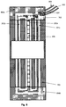
- FIG. 8 is a top view of the embodiment of FIG. 7 ;
- FIG. 9 shows an embodiment with static magnet row and moveable carriage fixed to magnetic circuits and windings
- FIG. 10 is a top view of the embodiment of FIG. 9 ;
- FIG. 11 shows a “delta” connection of the windings to a three phase current supply
- FIG. 12 shows a “star” connection of the windings to a three phase current supply
- FIG. 13 shows the geometrical shape of the magnetic circuits for a second embodiment
- FIG. 14 shows a wider magnet row as an alternative to the embodiment of FIG. 4 .
- the present invention provides an improved type of transverse flux motor.
- FIG. 1 a schematic view of the prior art Villaret design is shown for reference in FIG. 1 and FIG. 1A .
- a detailed explanation is found in U.S. Pat. No. 9,252,650 by Villaret.
- Three linear structures, 102 a , 102 b and 102 c are disposed parallel to the path of movement. Sections of windings are disposed in these linear structures. These linear structures are fixed to magnet rows 103 a , 103 b and 103 c respectively. Magnetic circuit 101 surrounding these structures is moving along the path. For use in a machine, the working load is mounted on a carriage fixed to the magnetic circuit 101 .
- the rigid mechanical link between carriage and magnetic circuit 101 provides a path for the heat coming from the magnetic circuit losses.
- a large and alternating current is run in the windings, creating a high magnetic field in the magnetic circuit.
- magnetic circuits have magnetic losses that dissipate in the form of heat, due to the non-linear magnetic property of the magnetic material. These losses are proportional to the square of the alternating current frequency and thus the speed.
- the working force is applied sequentially between the magnet rows 103 a , 103 b and 103 c and the magnetic circuit opening in which they are inserted.
- the working force on the carriage is sequentially applied at the three openings. If the gravity center of the carriage is for example in the center shown in G of FIG. 1 , an alternating torsional torque is applied on carriage during movement. This alternating torque produces vibrations in relation with the mechanical rigidity of the moving elements. In order to avoid these vibrations, a very rigid mechanical system must be used, resulting in heavy and expensive construction.
- FIG. 1A there is shown an embodiment of the prior art Villaret design where the linear bearing 108 a and 108 b are shown.
- the position of the bearing was selected for the best mechanical support of the magnetic circuit and the carriage.
- extremities 101 a and 101 b of the magnetic circuit are not directly supported, and thus will show some flexibility. They are subject to a variable attraction force to the magnet row. This variable magnetic force applied at these extremities will cause vibrations. These vibrations will in turn cause variations of the relative position of the magnet row and thus creates additional variation of the working force. Finally, undesirable vibrations will occur.
- the system structure should be made very rigid in order to reduce their amplitude, resulting in a heavy and expensive system
- the volume of space enclosed between the base-plate 109 , magnet rows 103 a , 103 b , 103 c and the winding structure 102 a , 102 b and 102 c is not easily accessible for the mounting of the magnetic circuit.
- magnetic circuit sections 101 c and 101 d should be mounted separately from the other sections of the magnetic circuit. Whenever the magnetic circuit is divided in several parts, the assembly process becomes very complex, in order to fix all parts together with high mechanical precision and also with high rigidity.
- a row of magnets 206 can linearly slide in the y direction of coordinate basis 210 inside the openings of three magnetic circuits 202 a , 202 b and 202 c and relative to them.
- the magnetic circuits are static and the magnet row slides inside their openings, or the magnet row is static and the magnetic circuits are moving and enclosing the magnet row.
- FIG. 4 shows a detailed description of the magnet row 206 .
- the magnet row 206 is composed of magnets ( 401 a 402 a . . . 401 d 402 d ) and non-magnetic material sections 403 a . . . 403 h . Magnets are equally distributed along the magnet row length, with alternate polarities.
- FIG. 4 shows the permanent magnets 401 a - 401 d having a north pole 405 filled in black, and a south pole 406 with a magnetic field exiting the magnet in the positive x directions shown by coordinate 410.
- Permanent magnets 402 a - 402 d are identical to permanent magnets 401 a - 401 d , but have opposite orientation, and produce a magnetic field in the negative x direction. Permanent magnets 401 a - 401 d and 402 a - 402 d are alternately disposed at equidistance along the row 206 . In the scope of this patent application, we shall refer to “period” as the distance between two magnets of the same polarity, as shown at 205 in FIG. 4 and FIG. 2 .
- long linear sections of windings 201 aa , 201 ab , 201 ba , 201 bb , 201 ca , 201 cb are disposed parallel to the sliding direction y.
- the sections 201 aa and 201 ab are part of the same winding 201 a shown in FIG. 3 , so that the current running inside each section will be of opposite direction.
- long linear winding sections 201 ba with 201 bb being part of winding 201 b
- long linear winding sections 201 ca with 201 cb being part of winding 201 c . It must be understood that different winding arrangements can be done within the scope of this invention.
- Magnetic circuits 202 a , 202 b and 202 c are made of laminated magnetizable material such as iron and iron alloy or composite, as used in electrical motors and transformers.
- Magnetic circuit 202 a encloses long linear sections of windings 201 aa and 201 bb .
- Magnetic circuit 202 b encloses long linear sections of windings 201 aa , 201 bb , 201 ab , 201 ca.
- Magnetic circuit 202 c encloses long linear sections of windings 201 aa , 201 bb , 201 ba , 201 cb.
- the three magnetic circuits 202 a , 202 b and 202 c are fixed to a common support (not shown).
- the distance between the magnetic circuits are shown in FIG. 2 as items 203 , 204 and are respectively 5 ⁇ 6 th and 1 ⁇ 3 rd of a period.
- the permanent magnets create a variable magnetic flux in the magnetic circuits. Due to the periodic disposition of the permanent magnets in the magnet row, and the set distances between the magnetic circuits, the created flux is a periodic function of the position in the direction of the path. This variable flux in turn creates a voltage in the windings.
- Each long linear winding section is enclosed by a number of magnetic circuits.
- the magnetic flux generated by the magnets of the magnet row generates a magnetic flux inside the magnetic circuits enclosing a long linear winding section.
- This generated flux traverses the winding of the long linear winding section, and a voltage is induced according to the time variation of the generated magnetic flux.
- a voltage is induced as the sum of all induced voltages.
- the flux in a magnetic circuit can be approximated to a sinusoidal function of the position x along the path. This is because of the periodic arrangement of the magnet row.
- a first winding 201 a includes the long linear winding sections 201 aa and 201 ab
- a second winding 201 b includes the long linear winding sections 201 ba and 201 bb
- the third winding 201 c includes the long linear winding sections 201 ca and 201 cb .
- the magnetic circuits geometry and the windings can be designed so that the same constant ⁇ 0 applies for all three winding.
- the electrical linear motor is thus capable of developing a working force between the magnet row 206 and the magnetic circuits 202 a , 202 b , 202 c , using only one magnet row 206 .
- the force is always applied between the magnet row 206 and the magnetic circuits, in the y direction shown in 210 .
- the three magnetic circuits 202 a , 202 b , 202 c shown in FIG. 2 form a set of magnetic circuits extending on a length along the movement path. Any number of such sets can be used, disposed along the path and mechanically linked in order to obtain a high working force. This is shown in the top view of FIG. 3 . A portion of a linear motor according to the preferred embodiment is seen showing two sets of magnetic circuits like 207 disposed along two period lengths. The set of magnetic circuits 207 is shown in FIG. 3 including three magnetic circuits 202 a 1 , 202 b 1 and 202 c 1 . There may any number of such magnetic circuit sets like 207 , in order to develop the required working force for the given application.
- This principle can be applied for different configurations of the moving and static elements.
- the winding and the magnetic circuits are static, and the magnet row is moving.
- a moving carriage 501 is sliding in a direction perpendicular to the plane of the figure, by means of two linear bearings 502 a and 502 b , over a frame structure 503 .
- a number of set of magnetic circuits 202 a , 202 b and 202 c are fixed inside the frame structure 503 , all along the moving range of the linear motor.
- a magnet row 206 is fixed to carriage 501 by mean of a fixing bar 504 , and slides inside the openings of the magnetic circuits.
- FIG. 6 shows a top view of this configuration.
- the sets of magnetic circuits are under the upper surface of the frame structure 503 , and the carriage 501 can move above the openings 605 of the magnetic circuits.
- the magnet row is situated under the carriage 501 , and its length is made shorter than the carriage length.
- the arrow 603 shows the sliding direction.
- the magnetic circuits must be divided in several sections.
- separating lines 505 , 506 , 507 and 508 are shown as gap between the upper and lower parts of the magnetic circuits. It must be understood that these gaps are very small and negligible, and during the assembly process the upper and lower parts are put in contact in order to ensure the continuity of the magnetic path.
- the magnetic circuit 202 a is divided in upper and lower part by gap 506 and 507 .
- Magnetic circuit 202 b is divided in upper and lower part by gap 508 and another gap not visible in FIG. 5 and situated behind magnetic circuit 202 a .
- Magnetic circuit 202 c is divided in upper and lower part by gap 505 and another gap not visible in FIG. 5 and situated behind magnetic circuit 202 b .
- lower part of magnetic circuit is first placed in the frame structure 503 , then windings are put in place, then upper parts of magnetic circuits are put in place.
- the magnet row is shorter than the length over which the magnetic circuit extends. It must be understood that the same configuration can be used where the magnet row is longer than the magnetic circuit. Such configuration can be useful for example in milling machines, in which the carriage is large and holds the working piece, and entirely covers and protects the static windings and magnetic circuits.
- a first particular advantage of this configuration is the small weight of the moving parts. This allows high accelerations and thus increased operating speed when used in automatic machines.
- a second particular advantage is that the moving part is passive, i.e. no moving cable is needed.
- the magnet row and the windings are static, and the magnetic circuits are movable along the path.
- the magnet row 206 is fixed to a base plate 703 by means of a fixing bar 704 , and fits inside the magnetic circuit openings.
- a holding structure 701 slides along the path by means of linear bearings 702 . Inside the holding structure 701 are fixed a number of sets of the magnetic circuits like 202 a , 202 b and 202 c .
- the magnetic circuits enclose and slide along the long linear sections of windings 201 aa , 201 ab , 201 ba , 201 bb , 201 ca , 201 cb.
- FIG. 8 there is shown a top view of this configuration.
- the windings are fixed to the base plate by means of two clamping structures 804 a and 804 b , by their extremities.
- the windings are designed according to well-known techniques in order to have a sufficient rigidity. It must be understood that the working force is not acting on the windings, so that the windings should be designed to self-support only.
- a first particular advantage of this configuration is that no moving cable is needed.
- a second particular advantage compared with the first configuration, is that only part of the long sections of the winding are surrounded by magnetic material. This reduces the magnetic loss and the inductance of the winding. This increases the efficiency of the motor.
- the magnet row is static, the windings and the magnetic circuits slide along the path.
- Magnet row 206 is fixed to a base plate 903 by means of a solid bar 904 .
- a holding structure 901 slides over the base plate by means of linear bearings 902 .
- Magnetic circuits 202 a , 202 b 202 c and windings are fixed inside the holding structure 901 .
- FIG. 9 the long linear sections of windings 201 aa 201 ab 201 ba 201 bb 201 ca and 201 cb can be seen.
- the openings of all magnetic circuits are all aligned along the path with the magnet row inside.
- FIG. 10 there is shown a top view.
- the windings and magnetic circuits are fixed inside the holding structure 901 , which slides over the base plate 903 .
- the electric cable connecting the windings 1001 to the driver (not shown) moves with the holding structure.
- the advantage over previous configurations is that the windings are shorter, thus reducing their resistance and power loss.
- moving cables are needed to provide the power to the windings.
- a lighter holding structure can be used, for a lower weight and cost.
- FIG. 11 there is shown a winding shape for the windings 201 a , 201 b and 201 c .
- Each winding includes several “turns” of a conducting wire. Each turn of wire extends along the winding shape.
- the rectangular shape of the windings provide long linear winding sections as 201 aa , 201 ab 201 ba 201 bb 201 ca 201 cb .
- Also shown is the electrical connection to a three phase controller (drive). The connection shown here is commonly called a “Delta” configuration.
- FIG. 12 there is shown the windings shape for the windings 201 a , 201 b and 201 c . Also shown is the electrical connection to a three phase controller (drive). The connection shown here is o commonly called a “Star” configuration.
- FIG. 13 there is shown another example of an embodiment.
- the magnetic circuit shape is designed so that magnetic circuit 131 a encloses the set of windings in long linear winding sections 201 bb and 201 aa , magnetic circuit 131 b encloses the set of windings in long linear winding sections 201 ab and 201 ca , and the magnetic circuit 131 c encloses the set of windings in long linear winding sections 201 cb and 201 ba .
- the particular shapes used here provide openings in which the magnet row 206 can be easily inserted inside the openings.
- the magnetic circuits extend over the whole length of the motor, and the magnet row is shorter, like for example the first embodiment described above in FIG. 5 and FIG. 6 , then only part of the magnetic circuits receives the magnet row; other magnetic circuits have their opening left open. The winding current still creates magnetic flux in these circuits.
- it is desirable to use a thin magnet row this is because the permanent magnet material has a low permeability, and thus the magnetic conductance of the magnetic circuit rapidly decreases with the thickness of the permanent magnets.
- the magnetic circuits that do not receive the magnet row have also a relatively low magnetic conductance. This will result in a high inductance of the windings, with high magnetic losses and will have a negative effect on the motor performance.
- FIG. 14 Such a magnet row 140 is shown in FIG. 14 .
- Four magnet modules 144 a , 144 b , 144 c and 144 d are shown, each module including two magnets of the same polarity like 142 and 143 , and a magnetizable material such as iron 141 between them.
- the opening of the magnetic circuits is sized to receive this wider magnet row.
- magnet 142 When inserted in the opening of the magnetic circuits, magnet 142 is in front of the right side of the opening, and magnet 143 in front of the left side.
- the four magnet modules are equidistant along the path of movement shown as the y direction of the coordinate basis 149 .
- the four magnet modules are fixed together by means of a non-magnetic material as shown by 145 between magnet modules 144 b and 144 c.
- the magnetic conductance of the magnetic circuits receiving the magnet row is high, because the magnetic material like 144 provides a good magnetic path, and the magnets are relatively thin.
- the magnetic circuits that do not receive the magnet row have a low magnetic conductance, due to the larger size of the openings. In this way, the inductance of the winding is reduced
- the invention has been described herein according to the preferred embodiments. It must be understood that many variations of the embodiments can be used according to the same principle, where a) the magnetic circuits provide aligned openings to receive one unique row, and b) each magnetic circuits enclose a set of long sections of the windings and at least two magnetic circuits enclose different set of long sections.
Abstract
Description
Φ=Φ0·sin(2*π*x/period+φ),
Φ0 is a constant depending on the number of winding turns, the geometry and material of the magnetic circuit and the magnetic strength of the permanent magnets;
φ is a phase depending on the position along the y direction of the magnetic circuit.
E=dΦ/dt=Φ0(2·π/period)·cos(2·π·x/period+φ)·dx/dt
E=Φ0·(2·π/period)·cos(2·π·x/period+φ)·V. (eq. 1)
F=Φ0·(2·π/period)·cos(2·π·x/period+φ)·I
Fu=Φ0·(2·π/period)·cos(2·π·x/period+φ)·Iu
Fv=Φ0·(2·π/period)·cos(2·π·x/period+
Fw=0·(2·π/period)·cos(2·π·x/period+φ+4·π/3)·Iw
Where Fu, Fv and Fw are the forces developed respectively by each winding current Iu, Iv and Iw in the
Iu=I0·cos(2*π*x/period+φ)
Iv=I0·cos(2*π*x/period+
Iw=I0·cos(2*·*x/period+φ+4·π/3),
-
- where I0 is a constant proportional to the required force output
F=Fu+Fv+Fw=(3/2)·Φ0·(2·π/period)·I0
Claims (15)
Priority Applications (1)
| Application Number | Priority Date | Filing Date | Title |
|---|---|---|---|
| US15/579,603 US10651718B2 (en) | 2015-07-20 | 2016-07-18 | Transverse flux linear motor |
Applications Claiming Priority (3)
| Application Number | Priority Date | Filing Date | Title |
|---|---|---|---|
| US201562194300P | 2015-07-20 | 2015-07-20 | |
| US15/579,603 US10651718B2 (en) | 2015-07-20 | 2016-07-18 | Transverse flux linear motor |
| PCT/IL2016/050783 WO2017013646A2 (en) | 2015-07-20 | 2016-07-18 | Transverse flux linear motor |
Publications (2)
| Publication Number | Publication Date |
|---|---|
| US20180166963A1 US20180166963A1 (en) | 2018-06-14 |
| US10651718B2 true US10651718B2 (en) | 2020-05-12 |
Family
ID=57835097
Family Applications (1)
| Application Number | Title | Priority Date | Filing Date |
|---|---|---|---|
| US15/579,603 Active 2037-02-07 US10651718B2 (en) | 2015-07-20 | 2016-07-18 | Transverse flux linear motor |
Country Status (7)
| Country | Link |
|---|---|
| US (1) | US10651718B2 (en) |
| EP (1) | EP3326276B1 (en) |
| JP (1) | JP6864844B2 (en) |
| KR (1) | KR102120569B1 (en) |
| CN (1) | CN107925336B (en) |
| DK (1) | DK3326276T3 (en) |
| WO (1) | WO2017013646A2 (en) |
Families Citing this family (3)
| Publication number | Priority date | Publication date | Assignee | Title |
|---|---|---|---|---|
| KR102120569B1 (en) | 2015-07-20 | 2020-06-09 | 모트엑스 엘티디. | Lateral flux linear motor |
| US10284040B1 (en) * | 2016-05-05 | 2019-05-07 | Charles David Craddock | Bipolar transverse flux electric motor |
| CN113556020B (en) * | 2021-07-16 | 2022-04-15 | 南京信息工程大学 | Back-to-back omega-shaped stator transverse flux permanent magnet linear motor |
Citations (14)
| Publication number | Priority date | Publication date | Assignee | Title |
|---|---|---|---|---|
| US4908533A (en) | 1988-01-15 | 1990-03-13 | Shinko Electric Co., Ltd. | Transporting apparatus |
| US5854521A (en) | 1995-04-27 | 1998-12-29 | Blum Gmbh | Multi-phase transverse magnetic flux machine |
| JP2002027729A (en) | 2000-07-06 | 2002-01-25 | Hitachi Kiden Kogyo Ltd | Linear motor |
| US20020050804A1 (en) | 2000-11-02 | 2002-05-02 | Joong Kim Houng | XYZ-axes table |
| US20020053835A1 (en) | 2000-11-06 | 2002-05-09 | Joong Kim Houng | Linear motor and method of producing the same |
| US20020053445A1 (en) | 2000-11-06 | 2002-05-09 | Kim Houng Joong | Power tool with a linear motor |
| US20030127917A1 (en) * | 2001-12-26 | 2003-07-10 | Kang Do Hyun | Transverse flux linear motor with permanent magnet excitation |
| US20070114854A1 (en) | 2003-07-16 | 2007-05-24 | Kabushiki Kaisha Yaskawa Denki | Moving magnet type linear actuator |
| DE102008012324A1 (en) | 2008-03-03 | 2009-09-17 | Continental Automotive Gmbh | Electric machine e.g. harmonic machine, for use in magnetic levitation system, has pole elements designed, so that magnetic fluxes are circulated in pole elements, without passing into pole elements that are activated by electric conductors |
| US20110241449A1 (en) | 2008-12-10 | 2011-10-06 | Yasuaki Aoyama | Thrust generation mechanism, drive device, xy stage and xyz stage |
| CN102292900A (en) | 2009-01-23 | 2011-12-21 | 日立金属株式会社 | Mover and linear motor |
| US20120205992A1 (en) * | 2009-08-31 | 2012-08-16 | Yves Villaret | Transverse flux electrical motor |
| US8810082B2 (en) * | 2009-03-13 | 2014-08-19 | Hitachi, Ltd. | Linear motor |
| WO2017013646A2 (en) | 2015-07-20 | 2017-01-26 | Motortronix Ltd. | Transverse flux linear motor |
Family Cites Families (7)
| Publication number | Priority date | Publication date | Assignee | Title |
|---|---|---|---|---|
| JP3815750B2 (en) * | 1995-10-09 | 2006-08-30 | キヤノン株式会社 | Stage apparatus, and exposure apparatus and device manufacturing method using the stage apparatus |
| KR100720753B1 (en) * | 2000-04-19 | 2007-05-22 | 가부시키가이샤 야스카와덴키 | Permanent magnet synchronous linear motor |
| JP4258969B2 (en) * | 2000-11-06 | 2009-04-30 | 株式会社日立製作所 | Permanent magnet magnetizing apparatus and magnetizing method |
| CN100592609C (en) * | 2006-09-28 | 2010-02-24 | 哈尔滨工业大学 | Horizontal flux flat-plate type permanent-magnetic linear electric machine |
| CN101834511B (en) * | 2010-04-30 | 2011-11-23 | 浙江大学 | Planar transverse magnetic flux switch flux linkage permanent magnet linear motor |
| CN202034884U (en) * | 2011-01-07 | 2011-11-09 | 青岛同日电机有限公司 | Permanent magnet linear synchronous motor |
| CN102299607B (en) * | 2011-08-25 | 2013-02-13 | 哈尔滨工业大学 | Transverse magnetic flux linear reluctance motor with offset permanent magnet |
-
2016
- 2016-07-18 KR KR1020187004199A patent/KR102120569B1/en active IP Right Grant
- 2016-07-18 US US15/579,603 patent/US10651718B2/en active Active
- 2016-07-18 CN CN201680043091.4A patent/CN107925336B/en active Active
- 2016-07-18 WO PCT/IL2016/050783 patent/WO2017013646A2/en active Application Filing
- 2016-07-18 EP EP16827360.5A patent/EP3326276B1/en active Active
- 2016-07-18 JP JP2017562346A patent/JP6864844B2/en active Active
- 2016-07-18 DK DK16827360.5T patent/DK3326276T3/en active
Patent Citations (18)
| Publication number | Priority date | Publication date | Assignee | Title |
|---|---|---|---|---|
| US4908533A (en) | 1988-01-15 | 1990-03-13 | Shinko Electric Co., Ltd. | Transporting apparatus |
| US5854521A (en) | 1995-04-27 | 1998-12-29 | Blum Gmbh | Multi-phase transverse magnetic flux machine |
| JP2002027729A (en) | 2000-07-06 | 2002-01-25 | Hitachi Kiden Kogyo Ltd | Linear motor |
| US20020050804A1 (en) | 2000-11-02 | 2002-05-02 | Joong Kim Houng | XYZ-axes table |
| US20020053835A1 (en) | 2000-11-06 | 2002-05-09 | Joong Kim Houng | Linear motor and method of producing the same |
| US20020053445A1 (en) | 2000-11-06 | 2002-05-09 | Kim Houng Joong | Power tool with a linear motor |
| CN1473386A (en) | 2000-11-06 | 2004-02-04 | 株式会社日立制作所 | Linear motor and method of producing the same |
| US20030127917A1 (en) * | 2001-12-26 | 2003-07-10 | Kang Do Hyun | Transverse flux linear motor with permanent magnet excitation |
| US20070114854A1 (en) | 2003-07-16 | 2007-05-24 | Kabushiki Kaisha Yaskawa Denki | Moving magnet type linear actuator |
| DE102008012324A1 (en) | 2008-03-03 | 2009-09-17 | Continental Automotive Gmbh | Electric machine e.g. harmonic machine, for use in magnetic levitation system, has pole elements designed, so that magnetic fluxes are circulated in pole elements, without passing into pole elements that are activated by electric conductors |
| US20110241449A1 (en) | 2008-12-10 | 2011-10-06 | Yasuaki Aoyama | Thrust generation mechanism, drive device, xy stage and xyz stage |
| CN102246401A (en) | 2008-12-10 | 2011-11-16 | 株式会社日立制作所 | Thrust generation mechanism, drive device, XY stage, and XYZ stage |
| CN102292900A (en) | 2009-01-23 | 2011-12-21 | 日立金属株式会社 | Mover and linear motor |
| US20140225459A1 (en) | 2009-01-23 | 2014-08-14 | Hitachi Metals, Ltd. | Mover and linear motor |
| US8810082B2 (en) * | 2009-03-13 | 2014-08-19 | Hitachi, Ltd. | Linear motor |
| US20120205992A1 (en) * | 2009-08-31 | 2012-08-16 | Yves Villaret | Transverse flux electrical motor |
| US9252650B2 (en) | 2009-08-31 | 2016-02-02 | Yaskawa Europe Technology Ltd. | Transverse flux electrical motor |
| WO2017013646A2 (en) | 2015-07-20 | 2017-01-26 | Motortronix Ltd. | Transverse flux linear motor |
Non-Patent Citations (7)
| Title |
|---|
| Examination Report Under Sections 12 & 13 of the Patents Act, 1970 and the Patents Rules, 2003 dated Oct. 18, 2019 From the Government of India, Intellectual Property India, Patents, Designs, Trade Marks, Geographical Indications Re. Application No. 201847005737. (5 Pages). |
| International Preliminary Report on Patentability dated Jun. 30, 2017 From the International Preliminary Examining Authority Re. Application No. PCT/IL2016/050783. (10 Pages). |
| International Search Report and the Written Opinion dated Jan. 13, 2017 dated Oct. 2015 From the International Searching Authority Re. Application No. PCT/IL2016/507839. (8 Pages). |
| Notice of Submission of Argument dated Jul. 25, 2019 From the Korean Intellectual Property Office Re. Application No. 10-2018-7004199 and Its Summary in English. (6 Pages). |
| Notification of Office Action and Search Report dated Jun. 4, 2019 From the China National Intellectual Property Administration Re. Application No. 201680043091.4 and Its Translation Into English. (16 Pages). |
| Supplementary European Search Report and the European Search Opinion dated Jan. 25, 2019 From the European Patent Office Re. Application No. 16827360.5. (9 Pages). |
| Translation Dated Sep. 26, 2019 of Notice of Submission of Argument dated Jul. 25, 2019 From the Korean Intellectual Property Office Re. Application No. 10-2018-7004199. (2 Pages). |
Also Published As
| Publication number | Publication date |
|---|---|
| US20180166963A1 (en) | 2018-06-14 |
| EP3326276A2 (en) | 2018-05-30 |
| EP3326276B1 (en) | 2021-03-31 |
| WO2017013646A8 (en) | 2017-04-06 |
| JP6864844B2 (en) | 2021-04-28 |
| DK3326276T3 (en) | 2021-07-05 |
| KR20180030864A (en) | 2018-03-26 |
| CN107925336B (en) | 2020-07-31 |
| WO2017013646A2 (en) | 2017-01-26 |
| EP3326276A4 (en) | 2019-02-27 |
| WO2017013646A3 (en) | 2017-03-09 |
| JP2018521617A (en) | 2018-08-02 |
| CN107925336A (en) | 2018-04-17 |
| KR102120569B1 (en) | 2020-06-09 |
Similar Documents
| Publication | Publication Date | Title |
|---|---|---|
| JP6848050B2 (en) | Electromechanical equipment | |
| JP6584619B2 (en) | Linear motor | |
| KR100785192B1 (en) | Coreless linear motor | |
| US8044541B2 (en) | Multi-degree-of-freedom actuator and stage device | |
| JP2000166214A (en) | Coaxial linear motor | |
| KR101810202B1 (en) | Magnetic array and magnetic suspension planar motor | |
| US10651718B2 (en) | Transverse flux linear motor | |
| CN107786058B (en) | Linear motor | |
| KR20210102190A (en) | polar linear synchronizer | |
| JP5150123B2 (en) | Direct acting electric actuator for vibration control | |
| KR100694673B1 (en) | Linear Motor using Cylindrical Permanent Magnet | |
| US9178406B2 (en) | Linear motor and stage device | |
| US9252650B2 (en) | Transverse flux electrical motor | |
| JP6732921B2 (en) | Electric machine | |
| JP2018148760A (en) | Linear motor | |
| JP3700883B2 (en) | Linear motor stator | |
| JP6408120B2 (en) | Linear motor | |
| JP2012060853A (en) | Actuator with two-degrees of freedom | |
| JP6058114B2 (en) | Linear motor | |
| KR20240001446A (en) | Coil moving type small size linear motor for high thrust force | |
| JP2012147517A (en) | Linear motor device and linear motor | |
| KR20240001447A (en) | Permanent magnet moving type small size linear motor for high thrust force |
Legal Events
| Date | Code | Title | Description |
|---|---|---|---|
| FEPP | Fee payment procedure |
Free format text: ENTITY STATUS SET TO UNDISCOUNTED (ORIGINAL EVENT CODE: BIG.); ENTITY STATUS OF PATENT OWNER: SMALL ENTITY |
|
| FEPP | Fee payment procedure |
Free format text: ENTITY STATUS SET TO SMALL (ORIGINAL EVENT CODE: SMAL); ENTITY STATUS OF PATENT OWNER: SMALL ENTITY |
|
| STPP | Information on status: patent application and granting procedure in general |
Free format text: DOCKETED NEW CASE - READY FOR EXAMINATION |
|
| STPP | Information on status: patent application and granting procedure in general |
Free format text: NON FINAL ACTION MAILED |
|
| STPP | Information on status: patent application and granting procedure in general |
Free format text: RESPONSE TO NON-FINAL OFFICE ACTION ENTERED AND FORWARDED TO EXAMINER |
|
| STPP | Information on status: patent application and granting procedure in general |
Free format text: NOTICE OF ALLOWANCE MAILED -- APPLICATION RECEIVED IN OFFICE OF PUBLICATIONS |
|
| AS | Assignment |
Owner name: MOTX LTD., ISRAEL Free format text: ASSIGNMENT OF ASSIGNORS INTEREST;ASSIGNOR:VILLARET, YVES;REEL/FRAME:051852/0333 Effective date: 20200211 |
|
| STCF | Information on status: patent grant |
Free format text: PATENTED CASE |
|
| MAFP | Maintenance fee payment |
Free format text: PAYMENT OF MAINTENANCE FEE, 4TH YR, SMALL ENTITY (ORIGINAL EVENT CODE: M2551); ENTITY STATUS OF PATENT OWNER: SMALL ENTITY Year of fee payment: 4 |