EP2618143A2 - Dispositif de commande de pression de fluide pour un analyseur - Google Patents
Dispositif de commande de pression de fluide pour un analyseur Download PDFInfo
- Publication number
- EP2618143A2 EP2618143A2 EP20130151775 EP13151775A EP2618143A2 EP 2618143 A2 EP2618143 A2 EP 2618143A2 EP 20130151775 EP20130151775 EP 20130151775 EP 13151775 A EP13151775 A EP 13151775A EP 2618143 A2 EP2618143 A2 EP 2618143A2
- Authority
- EP
- European Patent Office
- Prior art keywords
- pressure
- valve
- fluid
- way valve
- pressurized fluid
- Prior art date
- Legal status (The legal status is an assumption and is not a legal conclusion. Google has not performed a legal analysis and makes no representation as to the accuracy of the status listed.)
- Granted
Links
- 239000012530 fluid Substances 0.000 title claims abstract description 250
- 238000009530 blood pressure measurement Methods 0.000 claims abstract description 70
- 238000004891 communication Methods 0.000 claims abstract description 19
- 238000000034 method Methods 0.000 claims description 14
- 238000011144 upstream manufacturing Methods 0.000 claims description 14
- 238000001514 detection method Methods 0.000 claims description 8
- 239000008280 blood Substances 0.000 claims description 5
- 210000004369 blood Anatomy 0.000 claims description 5
- 230000008859 change Effects 0.000 claims description 3
- 238000004868 gas analysis Methods 0.000 claims description 3
- 239000007789 gas Substances 0.000 description 58
- 239000000126 substance Substances 0.000 description 12
- CURLTUGMZLYLDI-UHFFFAOYSA-N Carbon dioxide Chemical compound O=C=O CURLTUGMZLYLDI-UHFFFAOYSA-N 0.000 description 8
- 229910002092 carbon dioxide Inorganic materials 0.000 description 6
- 239000001569 carbon dioxide Substances 0.000 description 6
- 239000000306 component Substances 0.000 description 6
- 239000007788 liquid Substances 0.000 description 5
- 230000008569 process Effects 0.000 description 5
- 239000000203 mixture Substances 0.000 description 4
- 239000000463 material Substances 0.000 description 3
- 238000010926 purge Methods 0.000 description 3
- IJGRMHOSHXDMSA-UHFFFAOYSA-N Atomic nitrogen Chemical compound N#N IJGRMHOSHXDMSA-UHFFFAOYSA-N 0.000 description 2
- 229910000831 Steel Inorganic materials 0.000 description 2
- 229910052782 aluminium Inorganic materials 0.000 description 2
- XAGFODPZIPBFFR-UHFFFAOYSA-N aluminium Chemical compound [Al] XAGFODPZIPBFFR-UHFFFAOYSA-N 0.000 description 2
- QVGXLLKOCUKJST-UHFFFAOYSA-N atomic oxygen Chemical compound [O] QVGXLLKOCUKJST-UHFFFAOYSA-N 0.000 description 2
- 230000006870 function Effects 0.000 description 2
- 231100001261 hazardous Toxicity 0.000 description 2
- 238000012423 maintenance Methods 0.000 description 2
- 238000005259 measurement Methods 0.000 description 2
- 239000001301 oxygen Substances 0.000 description 2
- 229910052760 oxygen Inorganic materials 0.000 description 2
- 230000000737 periodic effect Effects 0.000 description 2
- 238000005057 refrigeration Methods 0.000 description 2
- 239000010959 steel Substances 0.000 description 2
- 229910001369 Brass Inorganic materials 0.000 description 1
- 229920000049 Carbon (fiber) Polymers 0.000 description 1
- 238000004458 analytical method Methods 0.000 description 1
- 238000013459 approach Methods 0.000 description 1
- 230000008901 benefit Effects 0.000 description 1
- 239000012503 blood component Substances 0.000 description 1
- 239000010951 brass Substances 0.000 description 1
- 239000004917 carbon fiber Substances 0.000 description 1
- 238000010276 construction Methods 0.000 description 1
- 230000008878 coupling Effects 0.000 description 1
- 238000010168 coupling process Methods 0.000 description 1
- 238000005859 coupling reaction Methods 0.000 description 1
- 238000010586 diagram Methods 0.000 description 1
- 238000009792 diffusion process Methods 0.000 description 1
- 239000011152 fibreglass Substances 0.000 description 1
- -1 for example Substances 0.000 description 1
- 230000002401 inhibitory effect Effects 0.000 description 1
- 229910052751 metal Inorganic materials 0.000 description 1
- 239000002184 metal Substances 0.000 description 1
- VNWKTOKETHGBQD-UHFFFAOYSA-N methane Chemical compound C VNWKTOKETHGBQD-UHFFFAOYSA-N 0.000 description 1
- 238000012986 modification Methods 0.000 description 1
- 230000004048 modification Effects 0.000 description 1
- 239000003507 refrigerant Substances 0.000 description 1
- 230000004044 response Effects 0.000 description 1
- 238000007789 sealing Methods 0.000 description 1
- 238000013519 translation Methods 0.000 description 1
- 239000002699 waste material Substances 0.000 description 1
Images


Classifications
-
- G—PHYSICS
- G01—MEASURING; TESTING
- G01N—INVESTIGATING OR ANALYSING MATERIALS BY DETERMINING THEIR CHEMICAL OR PHYSICAL PROPERTIES
- G01N27/00—Investigating or analysing materials by the use of electric, electrochemical, or magnetic means
- G01N27/26—Investigating or analysing materials by the use of electric, electrochemical, or magnetic means by investigating electrochemical variables; by using electrolysis or electrophoresis
- G01N27/416—Systems
- G01N27/4163—Systems checking the operation of, or calibrating, the measuring apparatus
-
- G—PHYSICS
- G01—MEASURING; TESTING
- G01N—INVESTIGATING OR ANALYSING MATERIALS BY DETERMINING THEIR CHEMICAL OR PHYSICAL PROPERTIES
- G01N33/00—Investigating or analysing materials by specific methods not covered by groups G01N1/00 - G01N31/00
- G01N33/0004—Gaseous mixtures, e.g. polluted air
- G01N33/0006—Calibrating gas analysers
-
- G—PHYSICS
- G01—MEASURING; TESTING
- G01N—INVESTIGATING OR ANALYSING MATERIALS BY DETERMINING THEIR CHEMICAL OR PHYSICAL PROPERTIES
- G01N33/00—Investigating or analysing materials by specific methods not covered by groups G01N1/00 - G01N31/00
- G01N33/48—Biological material, e.g. blood, urine; Haemocytometers
- G01N33/483—Physical analysis of biological material
- G01N33/487—Physical analysis of biological material of liquid biological material
- G01N33/49—Blood
- G01N33/4925—Blood measuring blood gas content, e.g. O2, CO2, HCO3
-
- Y—GENERAL TAGGING OF NEW TECHNOLOGICAL DEVELOPMENTS; GENERAL TAGGING OF CROSS-SECTIONAL TECHNOLOGIES SPANNING OVER SEVERAL SECTIONS OF THE IPC; TECHNICAL SUBJECTS COVERED BY FORMER USPC CROSS-REFERENCE ART COLLECTIONS [XRACs] AND DIGESTS
- Y10—TECHNICAL SUBJECTS COVERED BY FORMER USPC
- Y10T—TECHNICAL SUBJECTS COVERED BY FORMER US CLASSIFICATION
- Y10T137/00—Fluid handling
- Y10T137/0318—Processes
- Y10T137/0396—Involving pressure control
-
- Y—GENERAL TAGGING OF NEW TECHNOLOGICAL DEVELOPMENTS; GENERAL TAGGING OF CROSS-SECTIONAL TECHNOLOGIES SPANNING OVER SEVERAL SECTIONS OF THE IPC; TECHNICAL SUBJECTS COVERED BY FORMER USPC CROSS-REFERENCE ART COLLECTIONS [XRACs] AND DIGESTS
- Y10—TECHNICAL SUBJECTS COVERED BY FORMER USPC
- Y10T—TECHNICAL SUBJECTS COVERED BY FORMER US CLASSIFICATION
- Y10T137/00—Fluid handling
- Y10T137/7722—Line condition change responsive valves
- Y10T137/7781—With separate connected fluid reactor surface
- Y10T137/7793—With opening bias [e.g., pressure regulator]
Definitions
- the controller of the fluid pressure control device may include a processor.
- the fluid pressure control device may include an analyzer downstream of the first valve in selective fluid communication with the pressurized fluid inlet. Additionally, a second valve may be disposed between the first valve and the analyzer.
- the analyzer may be a blood gas analyzer. In at least one aspect of the disclosure the first pressure measurement device detects a change in fluid pressure between the first valve and the analyzer.
- the fluid pressure control device may include a second pressure measurement device is disposed upstream of the first valve and senses a fluid pressure upstream of the first valve.
- a second pressure measurement device is disposed upstream of the first valve and senses a fluid pressure upstream of the first valve.
- the first valve opens for a specified time period.
- the first valve opens until a sensed fluid pressure at the first pressure measurement device exceeds a second threshold.
- the fluid pressure control device may include an orifice having an internal diameter, the internal diameter of the orifice different than at least a portion of the internal diameter of a lumen fluidly connecting the first valve and the analyzer.
- the method may include sensing a pressure of the fluid in the pressurized fluid source vessel. Additionally, upon detection of a pressure of fluid in the pressurized fluid source vessel in excess of a second threshold, the period that the two-way valve is opened is set to a fixed time period. Alternatively or in addition, upon detection of a pressure of fluid in the pressurized fluid source vessel less than a second threshold, the two-way valve may be opened until the sensed pressure at the location between the three-way valve and the two-way valve exceeds a third threshold.
- the fluid from the pressurized fluid source vessel may be a gas.
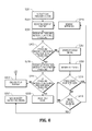
- Fig. 6 is a flowchart illustrating the control process of a gas analyzer system according to the present disclosure.
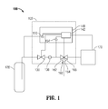
- the first valve 130 Downstream from the HP pressure measurement device 150 is a first valve 130.
- the first valve 130 is a fast-switching valve that controls the flow of pressurized fluid from the pressurized fluid supply 120 to the gas analyzer system 100. In an open position, first valve 130 fluidly connects the pressurized fluid supply 120 allowing pressurized fluid to flow from the pressurized fluid supply 120, and in a closed position isolates the pressurized fluid supply 120.
- the first valve 130 may be a two-way valve having an inlet and an outlet, and as shown in FIG. 1 , the pressurized fluid supply 120 is in fluid communication with the inlet of the two-way valve.
- First valve 130 may be electromechanically operated using for example, a solenoid.
- First valve 130 may be a direct operated solenoid valve, such as a Series S070 3 Port Solenoid Valve (available from SMC® Corporation of America).
- the first valve 130 may be any suitable flow control device configured to control the flow of pressurized fluids downstream of the pressurized fluid supply 120.
- Disposed downstream of the first valve 130 is a low-pressure (LP) pressure measurement device 154.
- An LP pressure measurement device 154 senses or detects a fluid pressure of the pressurized fluid between the first valve 130 and a second valve 160, as will be discussed further below.
- the first valve 130 can be actuated in response to the pressure detected by the LP pressure measurement device 154. By quickly opening and closing the first valve 130, a small volume of pressurized fluid is allowed to pass the first valve 130.
- HP pressure measurement device 150 and LP pressure measurement device 154 may be a surface-mounted package such as an NPP-301 Series Surface Mount Pressure Sensor (available from General Electric Company).
- the pressure measurement devices 150, 154 may incorporate transducers or any other suitable pressure sensor.
- the second valve 160 is disposed downstream of the LP pressure measurement device 154.
- the second valve 160 may be configured to operate similarly to first valve 130, discussed above, in that it may be solenoid operated.
- second valve 160 is a three-way valve that has a normally closed calibration gas inlet 162 in fluid communication with the pressurized fluid supply 120, a normally open atmospheric gas inlet 164 in fluid communication with atmosphere, and a common outlet 166 in fluid communication with an analyzer 170. By selectively switching which ports of the second valve 160 are connected, the second valve 160 can provide either atmospheric gas or pressurized fluid from the pressurized fluid supply 120 to the analyzer 170, which is in fluid communication with the common outlet 166.
- Fluid pressure control device 102 receives pressurized fluid supply 120 through pressurized fluid supply receiver 112.
- Pressurized fluid supply 120 may be attached to the pressurized fluid supply receiver 112 of the housing 110 by a threaded connection.
- a bayonet-type coupling or a clamp may be utilized.
- controller 140 includes one or more algorithms that dictate the manner in which the first valve 130 opens and closes.
- the algorithms are implemented based on the detected pressure of the pressurized fluid source 120.
- the algorithms of the controller cause the first valve 130 to open for a longer period of time when the pressure detected by HP pressure measurement device 150 is lower.
- the algorithms take into account the higher velocities and mass flow rates inherent in higher pressure fluid flows and adjusts the performance of the first valve 130 accordingly.
- the controller 140 signals the first valve 130 to open [S113], providing pressurized fluid at a higher pressure to the fluid pressure control device 102 from the pressurized fluid supply 120.
- the period of time that the first valve 130 is open is dictated by the algorithms described above, taking into account the pressure of the pressurized fluid supply 120 [S 115, S 117, S 119, S121, S123]. Once the period that the first valve 130 is open has elapsed or the desired pressure at the LP pressure measurement device 154 has been achieved, the first valve 130 is closed [S125].
- the controller 140 receives a signal representative of the pressure sensed or detected by the HP pressure measurement device 150 to determine whether the pressurized fluid supply 120 requires replacement, and the cycle repeats as long as power is supplied to the controller 140.
- the routine for control of the first valve 130 is initiated, as described above with reference to Fig. 5 .
- the pressure sensed or detected by the LP pressure measurement device 154 can be maintained substantially constant, and at a pressure lower than that of the pressurized fluid supply 120.
- a signal is sent to the controller 140 to perform a start-up routine [S203].
- controller 140 receives a pressure reading from HP pressure measurement device 150 [S204]. If the pressurized fluid supply 120 has been depleted, an alarm may indicate the status to the user [S205, S207]. In some embodiments this may result in the immediate shutting down of the gas analyzer system 100.
- a device interlock may be initiated [S209] after generation of the error signal [S207]. The device interlock prevents the analyzer 170 from being calibrated or having its calibration cycle run when there is insufficient pressurized fluid in the pressurized fluid supply 120.
- the gas analyzer system 100 may remain powered and wait a period of time [S215] for replacement of the pressurized fluid supply 120 [S213]. If the pressurized fluid supply 120 is not replaced within the maximum time period the gas analyzer system 100 shuts off [S227]. However, if prior to exceeding the maximum time since the interlock was initiated [S209] the pressurized fluid supply 120 is replaced [S213] the error signal will be cleared, the device interlock is removed [S210], and the start-up routine [S203] is re-initiated.
- the HP pressure measurement device 150 pressure is above 5 psi, indicating that calibration is possible [S205]
- the pressure at the LP pressure measurement device 154 is sensed or detected [S219]. If the detected LP pressure measurement device 154 is above about 2 psi, this indicates that the analyzer 170 is ready for operation and pressurized fluid is sufficiently pressurized and available for use.
- the startup routine is ended [S223] and operation of the fluid pressure control device 102 continues as described above with respect to Fig. 5 , starting at reference A.
- a pump (not shown) is disposed in the analyzer 170, and is fluidly coupled to the common outlet 166 of the second valve 160.
- the common outlet 166 of the second valve 160 is connected to the normally open atmospheric inlet 164 of the second valve 160, which is open to the atmosphere.
- the controller 140 Upon receiving a request for pressurized fluid from the analyzer 170, the controller 140 will switch the second valve 160 from its normally open position, where the pump is connected to the atmosphere, to a position connecting the calibration gas inlet 162 to the pump. To achieve this connection, the second valve 160 will be switched to connect the normally closed calibration gas inlet 162 with the common outlet 166.
- the volume of pressurized fluid that must flow through the analyzer 170 is more than required for calibration due to the fact that some volume of the pressurized fluid is used to purge the gas analyzer system 100 and ensure that no residual atmospheric gas is mixed with the calibration gas in the calibration process.
Landscapes
- Health & Medical Sciences (AREA)
- Life Sciences & Earth Sciences (AREA)
- Chemical & Material Sciences (AREA)
- Engineering & Computer Science (AREA)
- Physics & Mathematics (AREA)
- Biomedical Technology (AREA)
- Immunology (AREA)
- Pathology (AREA)
- Analytical Chemistry (AREA)
- Biochemistry (AREA)
- General Health & Medical Sciences (AREA)
- General Physics & Mathematics (AREA)
- Medicinal Chemistry (AREA)
- Food Science & Technology (AREA)
- Hematology (AREA)
- Molecular Biology (AREA)
- Ecology (AREA)
- Combustion & Propulsion (AREA)
- Biophysics (AREA)
- Urology & Nephrology (AREA)
- Chemical Kinetics & Catalysis (AREA)
- Electrochemistry (AREA)
- Sampling And Sample Adjustment (AREA)
- Control Of Fluid Pressure (AREA)
- Measuring Fluid Pressure (AREA)
Applications Claiming Priority (1)
| Application Number | Priority Date | Filing Date | Title |
|---|---|---|---|
| US201261588416P | 2012-01-19 | 2012-01-19 |
Publications (3)
| Publication Number | Publication Date |
|---|---|
| EP2618143A2 true EP2618143A2 (fr) | 2013-07-24 |
| EP2618143A3 EP2618143A3 (fr) | 2013-08-28 |
| EP2618143B1 EP2618143B1 (fr) | 2015-05-27 |
Family
ID=47561435
Family Applications (1)
| Application Number | Title | Priority Date | Filing Date |
|---|---|---|---|
| EP13151775.7A Active EP2618143B1 (fr) | 2012-01-19 | 2013-01-18 | Analyseur avec un dispositif de commande de pression de fluide |
Country Status (2)
| Country | Link |
|---|---|
| US (1) | US9151731B2 (fr) |
| EP (1) | EP2618143B1 (fr) |
Cited By (1)
| Publication number | Priority date | Publication date | Assignee | Title |
|---|---|---|---|---|
| GB2580634A (en) * | 2019-01-18 | 2020-07-29 | Roger Deas Alexander | Automatic bump test device |
Families Citing this family (7)
| Publication number | Priority date | Publication date | Assignee | Title |
|---|---|---|---|---|
| EP2908024B1 (fr) * | 2014-02-17 | 2023-09-06 | Special Springs S.r.l. | Appareil destiné à la pressurisation contrôlée d'actionneurs de cylindre à gaz |
| US9915225B2 (en) | 2015-02-06 | 2018-03-13 | United Technologies Corporation | Propulsion system arrangement for turbofan gas turbine engine |
| JP7107648B2 (ja) * | 2017-07-11 | 2022-07-27 | 株式会社堀場エステック | 流体制御装置、流体制御システム、流体制御方法、及び、流体制御装置用プログラム |
| US10649471B2 (en) * | 2018-02-02 | 2020-05-12 | Mks Instruments, Inc. | Method and apparatus for pulse gas delivery with isolation valves |
| US10725484B2 (en) | 2018-09-07 | 2020-07-28 | Mks Instruments, Inc. | Method and apparatus for pulse gas delivery using an external pressure trigger |
| US11609586B2 (en) * | 2019-10-13 | 2023-03-21 | Aaron Dwayne Lawson | Apparatuses for facilitating relieving pressure in a fluid transportation system |
| EP3882737B1 (fr) * | 2020-03-20 | 2022-04-27 | Siemens Aktiengesellschaft | Appareil de commande de pression de fluide |
Citations (1)
| Publication number | Priority date | Publication date | Assignee | Title |
|---|---|---|---|---|
| EP1207390A2 (fr) | 2000-11-15 | 2002-05-22 | Leco Corporation | Système d'analyse pour la détermination à grande précision de la teneur en nitrogène |
Family Cites Families (34)
| Publication number | Priority date | Publication date | Assignee | Title |
|---|---|---|---|---|
| US4373549A (en) * | 1979-02-12 | 1983-02-15 | Hewlett-Packard Company | Mass flow/pressure control system |
| US4394871A (en) * | 1980-12-31 | 1983-07-26 | The Boeing Company | Programmable pressure regulator for titanium superplastic forming apparatus |
| JPS63304133A (ja) * | 1987-06-05 | 1988-12-12 | Hitachi Ltd | 混合ガスを用いる分析計 |
| US5061631A (en) * | 1988-10-14 | 1991-10-29 | Fisher Scientific Company | Method, apparatus and solution for calibration of partial pressure value |
| JP2731950B2 (ja) * | 1989-07-13 | 1998-03-25 | キヤノン株式会社 | 露光方法 |
| DE4026492A1 (de) * | 1990-08-22 | 1992-02-27 | Klaus Stephan | Vorrichtung mit pulsventil zur dosierbaren ausgabe von gasen |
| US5357953A (en) * | 1992-05-21 | 1994-10-25 | Puritan-Bennett Corporation | Measurement device and method of calibration |
| FR2695704B1 (fr) | 1992-09-15 | 1994-10-14 | Imaje | Régulateur de pression pneumatique à commande électronique et procédé de régulation de pression d'un fluide utilisant un tel régulateur. |
| US5443087A (en) | 1993-12-13 | 1995-08-22 | Melea Limited | Method and system for controlling a pressurized fluid and valve assembly for use therein |
| US5672882A (en) * | 1995-12-29 | 1997-09-30 | Advanced Micro Devices, Inc. | Ion implantation device with a closed-loop process chamber pressure control system |
| GB2316773B (en) * | 1996-06-12 | 1999-09-29 | Gas Technology Canada | Electronic gas regulator |
| GB9724168D0 (en) | 1997-11-14 | 1998-01-14 | Air Prod & Chem | Gas control device and method of supplying gas |
| US5954089A (en) * | 1998-04-17 | 1999-09-21 | Trw Inc. | Electromagnetic regulator utilizing alternate valve operating modes for gas pressure regulation |
| DE19914282A1 (de) * | 1999-03-30 | 2000-10-05 | Leybold Vakuum Gmbh | Sperrgas-Ventileinrichtung |
| US6581623B1 (en) * | 1999-07-16 | 2003-06-24 | Advanced Technology Materials, Inc. | Auto-switching gas delivery system utilizing sub-atmospheric pressure gas supply vessels |
| US6782906B2 (en) * | 2000-12-28 | 2004-08-31 | Young-Chul Chang | Time based mass flow controller and method for controlling flow rate using it |
| US6568416B2 (en) | 2001-02-28 | 2003-05-27 | Brian L. Andersen | Fluid flow control system, fluid delivery and control system for a fluid delivery line, and method for controlling pressure oscillations within fluid of a fluid delivery line |
| US6913031B2 (en) * | 2001-10-18 | 2005-07-05 | Ckd Corporation | Pulse shot type flow controller and pulse shot type flow controlling method |
| DE10216143A1 (de) * | 2002-04-12 | 2003-10-23 | Bayer Ag | Vorrichtung zur Dosierung von Gasen |
| US6857447B2 (en) * | 2002-06-10 | 2005-02-22 | Advanced Technology Materials, Inc. | Pressure-based gas delivery system and method for reducing risks associated with storage and delivery of high pressure gases |
| JP4020016B2 (ja) * | 2003-05-28 | 2007-12-12 | 株式会社島津製作所 | ガスクロマトグラフ |
| US6997347B2 (en) * | 2003-07-02 | 2006-02-14 | Industrial Scientific Corporation | Apparatus and method for generating calibration gas |
| JP4646920B2 (ja) * | 2003-12-12 | 2011-03-09 | セメクイップ, インコーポレイテッド | イオン注入における設備の動作可能時間を延長するための方法および装置 |
| US7740024B2 (en) * | 2004-02-12 | 2010-06-22 | Entegris, Inc. | System and method for flow monitoring and control |
| US7083487B2 (en) * | 2004-04-02 | 2006-08-01 | John Weinel | Emergency flotation and recovery device |
| US7258132B2 (en) * | 2004-06-18 | 2007-08-21 | Agilent Technologies, Inc. | Electronically controlled back pressure regulator |
| US7680534B2 (en) | 2005-02-28 | 2010-03-16 | Cardiac Pacemakers, Inc. | Implantable cardiac device with dyspnea measurement |
| US20070186982A1 (en) * | 2006-02-10 | 2007-08-16 | Cohen Joseph P | Method for dispensing compressed gas |
| KR101840047B1 (ko) | 2008-01-18 | 2018-03-19 | 피포탈 시스템즈 코포레이션 | 가스 유동 제어기의 인 시투 시험을 위한 방법 및 장치 |
| TWI435196B (zh) * | 2009-10-15 | 2014-04-21 | Pivotal Systems Corp | 氣體流量控制方法及裝置 |
| US9429499B2 (en) * | 2010-10-29 | 2016-08-30 | Agilent Technologies, Inc. | Methods, devices, and systems for controlling the rate of gas depressurization within a vial containing a gas sample |
| US9400004B2 (en) * | 2010-11-29 | 2016-07-26 | Pivotal Systems Corporation | Transient measurements of mass flow controllers |
| US8831792B2 (en) * | 2011-06-28 | 2014-09-09 | GM Global Technology Operations LLC | Redundant adaptive algorithm for electrical pressure regulated high pressure tank systems |
| US8785071B2 (en) * | 2011-11-03 | 2014-07-22 | GM Global Technology Operations LLC | Fuel cell operation with a failed open injector |
-
2013
- 2013-01-18 US US13/744,458 patent/US9151731B2/en active Active
- 2013-01-18 EP EP13151775.7A patent/EP2618143B1/fr active Active
Patent Citations (1)
| Publication number | Priority date | Publication date | Assignee | Title |
|---|---|---|---|---|
| EP1207390A2 (fr) | 2000-11-15 | 2002-05-22 | Leco Corporation | Système d'analyse pour la détermination à grande précision de la teneur en nitrogène |
Cited By (1)
| Publication number | Priority date | Publication date | Assignee | Title |
|---|---|---|---|---|
| GB2580634A (en) * | 2019-01-18 | 2020-07-29 | Roger Deas Alexander | Automatic bump test device |
Also Published As
| Publication number | Publication date |
|---|---|
| EP2618143B1 (fr) | 2015-05-27 |
| US9151731B2 (en) | 2015-10-06 |
| US20130186475A1 (en) | 2013-07-25 |
| EP2618143A3 (fr) | 2013-08-28 |
Similar Documents
| Publication | Publication Date | Title |
|---|---|---|
| EP2618143B1 (fr) | Analyseur avec un dispositif de commande de pression de fluide | |
| US7146841B2 (en) | Gas sensor calibration system | |
| US6164116A (en) | Gas module valve automated test fixture | |
| KR102280026B1 (ko) | 혼합 가스 공급 장치 | |
| AU2002222165A1 (en) | Gas sensor calibration system | |
| CN108088710B (zh) | 具有泵机构、检查气体测量系统的气体引导元件工作预备性用的装置 | |
| US7845206B2 (en) | System, apparatus and method for dispensing chemical vapor | |
| US9482653B2 (en) | Gas exchange system flow configuration | |
| US11703484B2 (en) | Sensor module | |
| US8610072B2 (en) | Gas exchange system flow configuration | |
| CN108088883B (zh) | 用于检查气体引导元件的检测装置 | |
| EP1403363A1 (fr) | Incubateur à CO2 | |
| JPH08501496A (ja) | 精密液体分注装置および方法 | |
| JP2009074824A (ja) | 分注装置および分注装置における吐出状態判定方法 | |
| US11067551B2 (en) | Device for measuring the amount of oxygen present in a gas, and air-separation module comprising such a measurement device | |
| RU2208783C1 (ru) | Устройство для приготовления поверочных газовых смесей | |
| EP3237885A1 (fr) | Analyseur de réfrigérant de contrefaçon | |
| KR20120053225A (ko) | 질소퍼지장치를 이용한 온도챔버의 발화방지 시스템 및 이를 이용한 발화방지 방법 | |
| JPH09292380A (ja) | 気体流量制御装置 |
Legal Events
| Date | Code | Title | Description |
|---|---|---|---|
| PUAI | Public reference made under article 153(3) epc to a published international application that has entered the european phase |
Free format text: ORIGINAL CODE: 0009012 |
|
| AK | Designated contracting states |
Kind code of ref document: A2 Designated state(s): AL AT BE BG CH CY CZ DE DK EE ES FI FR GB GR HR HU IE IS IT LI LT LU LV MC MK MT NL NO PL PT RO RS SE SI SK SM TR |
|
| AX | Request for extension of the european patent |
Extension state: BA ME |
|
| PUAL | Search report despatched |
Free format text: ORIGINAL CODE: 0009013 |
|
| AK | Designated contracting states |
Kind code of ref document: A3 Designated state(s): AL AT BE BG CH CY CZ DE DK EE ES FI FR GB GR HR HU IE IS IT LI LT LU LV MC MK MT NL NO PL PT RO RS SE SI SK SM TR |
|
| AX | Request for extension of the european patent |
Extension state: BA ME |
|
| RIC1 | Information provided on ipc code assigned before grant |
Ipc: G01N 33/49 20060101ALI20130719BHEP Ipc: G01N 33/00 20060101AFI20130719BHEP |
|
| 17P | Request for examination filed |
Effective date: 20140129 |
|
| RBV | Designated contracting states (corrected) |
Designated state(s): AL AT BE BG CH CY CZ DE DK EE ES FI FR GB GR HR HU IE IS IT LI LT LU LV MC MK MT NL NO PL PT RO RS SE SI SK SM TR |
|
| 17Q | First examination report despatched |
Effective date: 20140724 |
|
| GRAP | Despatch of communication of intention to grant a patent |
Free format text: ORIGINAL CODE: EPIDOSNIGR1 |
|
| INTG | Intention to grant announced |
Effective date: 20141212 |
|
| GRAS | Grant fee paid |
Free format text: ORIGINAL CODE: EPIDOSNIGR3 |
|
| GRAA | (expected) grant |
Free format text: ORIGINAL CODE: 0009210 |
|
| AK | Designated contracting states |
Kind code of ref document: B1 Designated state(s): AL AT BE BG CH CY CZ DE DK EE ES FI FR GB GR HR HU IE IS IT LI LT LU LV MC MK MT NL NO PL PT RO RS SE SI SK SM TR |
|
| REG | Reference to a national code |
Ref country code: GB Ref legal event code: FG4D |
|
| REG | Reference to a national code |
Ref country code: CH Ref legal event code: EP |
|
| REG | Reference to a national code |
Ref country code: AT Ref legal event code: REF Ref document number: 729127 Country of ref document: AT Kind code of ref document: T Effective date: 20150615 |
|
| REG | Reference to a national code |
Ref country code: IE Ref legal event code: FG4D |
|
| REG | Reference to a national code |
Ref country code: DE Ref legal event code: R096 Ref document number: 602013001818 Country of ref document: DE Effective date: 20150709 |
|
| REG | Reference to a national code |
Ref country code: AT Ref legal event code: MK05 Ref document number: 729127 Country of ref document: AT Kind code of ref document: T Effective date: 20150527 |
|
| REG | Reference to a national code |
Ref country code: LT Ref legal event code: MG4D |
|
| PG25 | Lapsed in a contracting state [announced via postgrant information from national office to epo] |
Ref country code: HR Free format text: LAPSE BECAUSE OF FAILURE TO SUBMIT A TRANSLATION OF THE DESCRIPTION OR TO PAY THE FEE WITHIN THE PRESCRIBED TIME-LIMIT Effective date: 20150527 Ref country code: FI Free format text: LAPSE BECAUSE OF FAILURE TO SUBMIT A TRANSLATION OF THE DESCRIPTION OR TO PAY THE FEE WITHIN THE PRESCRIBED TIME-LIMIT Effective date: 20150527 Ref country code: ES Free format text: LAPSE BECAUSE OF FAILURE TO SUBMIT A TRANSLATION OF THE DESCRIPTION OR TO PAY THE FEE WITHIN THE PRESCRIBED TIME-LIMIT Effective date: 20150527 Ref country code: PT Free format text: LAPSE BECAUSE OF FAILURE TO SUBMIT A TRANSLATION OF THE DESCRIPTION OR TO PAY THE FEE WITHIN THE PRESCRIBED TIME-LIMIT Effective date: 20150928 Ref country code: NO Free format text: LAPSE BECAUSE OF FAILURE TO SUBMIT A TRANSLATION OF THE DESCRIPTION OR TO PAY THE FEE WITHIN THE PRESCRIBED TIME-LIMIT Effective date: 20150827 Ref country code: LT Free format text: LAPSE BECAUSE OF FAILURE TO SUBMIT A TRANSLATION OF THE DESCRIPTION OR TO PAY THE FEE WITHIN THE PRESCRIBED TIME-LIMIT Effective date: 20150527 |
|
| REG | Reference to a national code |
Ref country code: NL Ref legal event code: MP Effective date: 20150527 |
|
| PG25 | Lapsed in a contracting state [announced via postgrant information from national office to epo] |
Ref country code: GR Free format text: LAPSE BECAUSE OF FAILURE TO SUBMIT A TRANSLATION OF THE DESCRIPTION OR TO PAY THE FEE WITHIN THE PRESCRIBED TIME-LIMIT Effective date: 20150828 Ref country code: RS Free format text: LAPSE BECAUSE OF FAILURE TO SUBMIT A TRANSLATION OF THE DESCRIPTION OR TO PAY THE FEE WITHIN THE PRESCRIBED TIME-LIMIT Effective date: 20150527 Ref country code: AT Free format text: LAPSE BECAUSE OF FAILURE TO SUBMIT A TRANSLATION OF THE DESCRIPTION OR TO PAY THE FEE WITHIN THE PRESCRIBED TIME-LIMIT Effective date: 20150527 Ref country code: BG Free format text: LAPSE BECAUSE OF FAILURE TO SUBMIT A TRANSLATION OF THE DESCRIPTION OR TO PAY THE FEE WITHIN THE PRESCRIBED TIME-LIMIT Effective date: 20150827 Ref country code: IS Free format text: LAPSE BECAUSE OF FAILURE TO SUBMIT A TRANSLATION OF THE DESCRIPTION OR TO PAY THE FEE WITHIN THE PRESCRIBED TIME-LIMIT Effective date: 20150927 Ref country code: LV Free format text: LAPSE BECAUSE OF FAILURE TO SUBMIT A TRANSLATION OF THE DESCRIPTION OR TO PAY THE FEE WITHIN THE PRESCRIBED TIME-LIMIT Effective date: 20150527 |
|
| REG | Reference to a national code |
Ref country code: FR Ref legal event code: PLFP Year of fee payment: 4 |
|
| PG25 | Lapsed in a contracting state [announced via postgrant information from national office to epo] |
Ref country code: DK Free format text: LAPSE BECAUSE OF FAILURE TO SUBMIT A TRANSLATION OF THE DESCRIPTION OR TO PAY THE FEE WITHIN THE PRESCRIBED TIME-LIMIT Effective date: 20150527 Ref country code: EE Free format text: LAPSE BECAUSE OF FAILURE TO SUBMIT A TRANSLATION OF THE DESCRIPTION OR TO PAY THE FEE WITHIN THE PRESCRIBED TIME-LIMIT Effective date: 20150527 |
|
| PG25 | Lapsed in a contracting state [announced via postgrant information from national office to epo] |
Ref country code: PL Free format text: LAPSE BECAUSE OF FAILURE TO SUBMIT A TRANSLATION OF THE DESCRIPTION OR TO PAY THE FEE WITHIN THE PRESCRIBED TIME-LIMIT Effective date: 20150527 Ref country code: RO Free format text: LAPSE BECAUSE OF NON-PAYMENT OF DUE FEES Effective date: 20150527 Ref country code: CZ Free format text: LAPSE BECAUSE OF FAILURE TO SUBMIT A TRANSLATION OF THE DESCRIPTION OR TO PAY THE FEE WITHIN THE PRESCRIBED TIME-LIMIT Effective date: 20150527 Ref country code: SK Free format text: LAPSE BECAUSE OF FAILURE TO SUBMIT A TRANSLATION OF THE DESCRIPTION OR TO PAY THE FEE WITHIN THE PRESCRIBED TIME-LIMIT Effective date: 20150527 |
|
| REG | Reference to a national code |
Ref country code: DE Ref legal event code: R097 Ref document number: 602013001818 Country of ref document: DE |
|
| PLBE | No opposition filed within time limit |
Free format text: ORIGINAL CODE: 0009261 |
|
| STAA | Information on the status of an ep patent application or granted ep patent |
Free format text: STATUS: NO OPPOSITION FILED WITHIN TIME LIMIT |
|
| RAP2 | Party data changed (patent owner data changed or rights of a patent transferred) |
Owner name: OPTI MEDICAL SYSTEMS, INC. |
|
| PG25 | Lapsed in a contracting state [announced via postgrant information from national office to epo] |
Ref country code: IT Free format text: LAPSE BECAUSE OF FAILURE TO SUBMIT A TRANSLATION OF THE DESCRIPTION OR TO PAY THE FEE WITHIN THE PRESCRIBED TIME-LIMIT Effective date: 20150527 |
|
| 26N | No opposition filed |
Effective date: 20160301 |
|
| PG25 | Lapsed in a contracting state [announced via postgrant information from national office to epo] |
Ref country code: SI Free format text: LAPSE BECAUSE OF FAILURE TO SUBMIT A TRANSLATION OF THE DESCRIPTION OR TO PAY THE FEE WITHIN THE PRESCRIBED TIME-LIMIT Effective date: 20150527 Ref country code: BE Free format text: LAPSE BECAUSE OF NON-PAYMENT OF DUE FEES Effective date: 20160131 |
|
| PG25 | Lapsed in a contracting state [announced via postgrant information from national office to epo] |
Ref country code: LU Free format text: LAPSE BECAUSE OF FAILURE TO SUBMIT A TRANSLATION OF THE DESCRIPTION OR TO PAY THE FEE WITHIN THE PRESCRIBED TIME-LIMIT Effective date: 20160118 Ref country code: BE Free format text: LAPSE BECAUSE OF FAILURE TO SUBMIT A TRANSLATION OF THE DESCRIPTION OR TO PAY THE FEE WITHIN THE PRESCRIBED TIME-LIMIT Effective date: 20150527 |
|
| REG | Reference to a national code |
Ref country code: CH Ref legal event code: PL |
|
| PG25 | Lapsed in a contracting state [announced via postgrant information from national office to epo] |
Ref country code: MC Free format text: LAPSE BECAUSE OF FAILURE TO SUBMIT A TRANSLATION OF THE DESCRIPTION OR TO PAY THE FEE WITHIN THE PRESCRIBED TIME-LIMIT Effective date: 20150527 |
|
| PG25 | Lapsed in a contracting state [announced via postgrant information from national office to epo] |
Ref country code: LI Free format text: LAPSE BECAUSE OF NON-PAYMENT OF DUE FEES Effective date: 20160131 Ref country code: CH Free format text: LAPSE BECAUSE OF NON-PAYMENT OF DUE FEES Effective date: 20160131 |
|
| REG | Reference to a national code |
Ref country code: IE Ref legal event code: MM4A |
|
| REG | Reference to a national code |
Ref country code: FR Ref legal event code: PLFP Year of fee payment: 5 |
|
| PG25 | Lapsed in a contracting state [announced via postgrant information from national office to epo] |
Ref country code: IE Free format text: LAPSE BECAUSE OF NON-PAYMENT OF DUE FEES Effective date: 20160118 |
|
| PG25 | Lapsed in a contracting state [announced via postgrant information from national office to epo] |
Ref country code: SE Free format text: LAPSE BECAUSE OF FAILURE TO SUBMIT A TRANSLATION OF THE DESCRIPTION OR TO PAY THE FEE WITHIN THE PRESCRIBED TIME-LIMIT Effective date: 20150527 Ref country code: NL Free format text: LAPSE BECAUSE OF FAILURE TO SUBMIT A TRANSLATION OF THE DESCRIPTION OR TO PAY THE FEE WITHIN THE PRESCRIBED TIME-LIMIT Effective date: 20150527 |
|
| PG25 | Lapsed in a contracting state [announced via postgrant information from national office to epo] |
Ref country code: MT Free format text: LAPSE BECAUSE OF FAILURE TO SUBMIT A TRANSLATION OF THE DESCRIPTION OR TO PAY THE FEE WITHIN THE PRESCRIBED TIME-LIMIT Effective date: 20150527 |
|
| REG | Reference to a national code |
Ref country code: FR Ref legal event code: PLFP Year of fee payment: 6 |
|
| PG25 | Lapsed in a contracting state [announced via postgrant information from national office to epo] |
Ref country code: SM Free format text: LAPSE BECAUSE OF FAILURE TO SUBMIT A TRANSLATION OF THE DESCRIPTION OR TO PAY THE FEE WITHIN THE PRESCRIBED TIME-LIMIT Effective date: 20150527 Ref country code: HU Free format text: LAPSE BECAUSE OF FAILURE TO SUBMIT A TRANSLATION OF THE DESCRIPTION OR TO PAY THE FEE WITHIN THE PRESCRIBED TIME-LIMIT; INVALID AB INITIO Effective date: 20130118 Ref country code: CY Free format text: LAPSE BECAUSE OF FAILURE TO SUBMIT A TRANSLATION OF THE DESCRIPTION OR TO PAY THE FEE WITHIN THE PRESCRIBED TIME-LIMIT Effective date: 20150527 |
|
| PG25 | Lapsed in a contracting state [announced via postgrant information from national office to epo] |
Ref country code: MT Free format text: LAPSE BECAUSE OF FAILURE TO SUBMIT A TRANSLATION OF THE DESCRIPTION OR TO PAY THE FEE WITHIN THE PRESCRIBED TIME-LIMIT Effective date: 20160131 Ref country code: TR Free format text: LAPSE BECAUSE OF FAILURE TO SUBMIT A TRANSLATION OF THE DESCRIPTION OR TO PAY THE FEE WITHIN THE PRESCRIBED TIME-LIMIT Effective date: 20150527 Ref country code: MK Free format text: LAPSE BECAUSE OF FAILURE TO SUBMIT A TRANSLATION OF THE DESCRIPTION OR TO PAY THE FEE WITHIN THE PRESCRIBED TIME-LIMIT Effective date: 20150527 |
|
| PG25 | Lapsed in a contracting state [announced via postgrant information from national office to epo] |
Ref country code: AL Free format text: LAPSE BECAUSE OF FAILURE TO SUBMIT A TRANSLATION OF THE DESCRIPTION OR TO PAY THE FEE WITHIN THE PRESCRIBED TIME-LIMIT Effective date: 20150527 |
|
| REG | Reference to a national code |
Ref country code: DE Ref legal event code: R082 Ref document number: 602013001818 Country of ref document: DE Representative=s name: VENNER SHIPLEY GERMANY LLP, DE Ref country code: DE Ref legal event code: R082 Ref document number: 602013001818 Country of ref document: DE Representative=s name: VENNER SHIPLEY LLP, DE |
|
| P01 | Opt-out of the competence of the unified patent court (upc) registered |
Effective date: 20230522 |
|
| PGFP | Annual fee paid to national office [announced via postgrant information from national office to epo] |
Ref country code: DE Payment date: 20240129 Year of fee payment: 12 Ref country code: GB Payment date: 20240129 Year of fee payment: 12 |
|
| PGFP | Annual fee paid to national office [announced via postgrant information from national office to epo] |
Ref country code: FR Payment date: 20240125 Year of fee payment: 12 |