EP2617663B1 - Tobacco package - Google Patents
Tobacco package Download PDFInfo
- Publication number
- EP2617663B1 EP2617663B1 EP13001931.8A EP13001931A EP2617663B1 EP 2617663 B1 EP2617663 B1 EP 2617663B1 EP 13001931 A EP13001931 A EP 13001931A EP 2617663 B1 EP2617663 B1 EP 2617663B1
- Authority
- EP
- European Patent Office
- Prior art keywords
- receptacle
- wall
- flap
- access opening
- package according
- Prior art date
- Legal status (The legal status is an assumption and is not a legal conclusion. Google has not performed a legal analysis and makes no representation as to the accuracy of the status listed.)
- Not-in-force
Links
Images


Classifications
-
- B—PERFORMING OPERATIONS; TRANSPORTING
- B65—CONVEYING; PACKING; STORING; HANDLING THIN OR FILAMENTARY MATERIAL
- B65D—CONTAINERS FOR STORAGE OR TRANSPORT OF ARTICLES OR MATERIALS, e.g. BAGS, BARRELS, BOTTLES, BOXES, CANS, CARTONS, CRATES, DRUMS, JARS, TANKS, HOPPERS, FORWARDING CONTAINERS; ACCESSORIES, CLOSURES, OR FITTINGS THEREFOR; PACKAGING ELEMENTS; PACKAGES
- B65D5/00—Rigid or semi-rigid containers of polygonal cross-section, e.g. boxes, cartons or trays, formed by folding or erecting one or more blanks made of paper
- B65D5/38—Drawer-and-shell type containers
-
- B—PERFORMING OPERATIONS; TRANSPORTING
- B65—CONVEYING; PACKING; STORING; HANDLING THIN OR FILAMENTARY MATERIAL
- B65D—CONTAINERS FOR STORAGE OR TRANSPORT OF ARTICLES OR MATERIALS, e.g. BAGS, BARRELS, BOTTLES, BOXES, CANS, CARTONS, CRATES, DRUMS, JARS, TANKS, HOPPERS, FORWARDING CONTAINERS; ACCESSORIES, CLOSURES, OR FITTINGS THEREFOR; PACKAGING ELEMENTS; PACKAGES
- B65D5/00—Rigid or semi-rigid containers of polygonal cross-section, e.g. boxes, cartons or trays, formed by folding or erecting one or more blanks made of paper
- B65D5/42—Details of containers or of foldable or erectable container blanks
- B65D5/4212—Information or decoration elements, e.g. content indicators, or for mailing
- B65D5/4233—Cards, coupons, labels or the like formed separately from the container or lid
-
- B—PERFORMING OPERATIONS; TRANSPORTING
- B65—CONVEYING; PACKING; STORING; HANDLING THIN OR FILAMENTARY MATERIAL
- B65D—CONTAINERS FOR STORAGE OR TRANSPORT OF ARTICLES OR MATERIALS, e.g. BAGS, BARRELS, BOTTLES, BOXES, CANS, CARTONS, CRATES, DRUMS, JARS, TANKS, HOPPERS, FORWARDING CONTAINERS; ACCESSORIES, CLOSURES, OR FITTINGS THEREFOR; PACKAGING ELEMENTS; PACKAGES
- B65D5/00—Rigid or semi-rigid containers of polygonal cross-section, e.g. boxes, cartons or trays, formed by folding or erecting one or more blanks made of paper
- B65D5/42—Details of containers or of foldable or erectable container blanks
- B65D5/44—Integral, inserted or attached portions forming internal or external fittings
- B65D5/48—Partitions
- B65D5/48024—Partitions inserted
- B65D5/48042—Strip provided with series of folding lines forming the partitions
-
- B—PERFORMING OPERATIONS; TRANSPORTING
- B65—CONVEYING; PACKING; STORING; HANDLING THIN OR FILAMENTARY MATERIAL
- B65D—CONTAINERS FOR STORAGE OR TRANSPORT OF ARTICLES OR MATERIALS, e.g. BAGS, BARRELS, BOTTLES, BOXES, CANS, CARTONS, CRATES, DRUMS, JARS, TANKS, HOPPERS, FORWARDING CONTAINERS; ACCESSORIES, CLOSURES, OR FITTINGS THEREFOR; PACKAGING ELEMENTS; PACKAGES
- B65D5/00—Rigid or semi-rigid containers of polygonal cross-section, e.g. boxes, cartons or trays, formed by folding or erecting one or more blanks made of paper
- B65D5/42—Details of containers or of foldable or erectable container blanks
- B65D5/44—Integral, inserted or attached portions forming internal or external fittings
- B65D5/48—Partitions
- B65D5/48024—Partitions inserted
- B65D5/48044—Blank provided with cut flaps folded perpendicular to the blank
-
- B—PERFORMING OPERATIONS; TRANSPORTING
- B65—CONVEYING; PACKING; STORING; HANDLING THIN OR FILAMENTARY MATERIAL
- B65D—CONTAINERS FOR STORAGE OR TRANSPORT OF ARTICLES OR MATERIALS, e.g. BAGS, BARRELS, BOTTLES, BOXES, CANS, CARTONS, CRATES, DRUMS, JARS, TANKS, HOPPERS, FORWARDING CONTAINERS; ACCESSORIES, CLOSURES, OR FITTINGS THEREFOR; PACKAGING ELEMENTS; PACKAGES
- B65D5/00—Rigid or semi-rigid containers of polygonal cross-section, e.g. boxes, cartons or trays, formed by folding or erecting one or more blanks made of paper
- B65D5/42—Details of containers or of foldable or erectable container blanks
- B65D5/64—Lids
- B65D5/66—Hinged lids
- B65D5/6626—Hinged lids formed by folding extensions of a side panel of a container body formed by erecting a "cross-like" blank
- B65D5/6682—Hinged lids formed by folding extensions of a side panel of a container body formed by erecting a "cross-like" blank the lid being hinged about a line located in the top surface of the container
-
- B—PERFORMING OPERATIONS; TRANSPORTING
- B65—CONVEYING; PACKING; STORING; HANDLING THIN OR FILAMENTARY MATERIAL
- B65D—CONTAINERS FOR STORAGE OR TRANSPORT OF ARTICLES OR MATERIALS, e.g. BAGS, BARRELS, BOTTLES, BOXES, CANS, CARTONS, CRATES, DRUMS, JARS, TANKS, HOPPERS, FORWARDING CONTAINERS; ACCESSORIES, CLOSURES, OR FITTINGS THEREFOR; PACKAGING ELEMENTS; PACKAGES
- B65D5/00—Rigid or semi-rigid containers of polygonal cross-section, e.g. boxes, cartons or trays, formed by folding or erecting one or more blanks made of paper
- B65D5/42—Details of containers or of foldable or erectable container blanks
- B65D5/72—Contents-dispensing means
- B65D5/721—Contents-dispensing means consisting of mobile elements forming part of the containers or attached to the containers
-
- B—PERFORMING OPERATIONS; TRANSPORTING
- B65—CONVEYING; PACKING; STORING; HANDLING THIN OR FILAMENTARY MATERIAL
- B65D—CONTAINERS FOR STORAGE OR TRANSPORT OF ARTICLES OR MATERIALS, e.g. BAGS, BARRELS, BOTTLES, BOXES, CANS, CARTONS, CRATES, DRUMS, JARS, TANKS, HOPPERS, FORWARDING CONTAINERS; ACCESSORIES, CLOSURES, OR FITTINGS THEREFOR; PACKAGING ELEMENTS; PACKAGES
- B65D85/00—Containers, packaging elements or packages, specially adapted for particular articles or materials
- B65D85/07—Containers, packaging elements or packages, specially adapted for particular articles or materials for compressible or flexible articles
- B65D85/08—Containers, packaging elements or packages, specially adapted for particular articles or materials for compressible or flexible articles rod-shaped or tubular
- B65D85/10—Containers, packaging elements or packages, specially adapted for particular articles or materials for compressible or flexible articles rod-shaped or tubular for cigarettes
- B65D85/1036—Containers formed by erecting a rigid or semi-rigid blank
- B65D85/1045—Containers formed by erecting a rigid or semi-rigid blank having a cap-like lid hinged to an edge
Definitions
- the invention relates to a package for tobacco, in particular for loose tobacco used for self-making or rolling cigarettes.
- a conventional package for loose tobacco is designed as a soft pouch with a flap for closing the access opening of the pouch.
- WO-A-8808602 upon which the preamble of claim 1 is based, discloses a cigarette package comprising two receptacles, which are foldable upon each other about longitudinally extending fold lines and are open at one of their respective end sides.
- the open end sides of both receptacles can be closed by a common lid, which is connected to one of the receptacles at a fold line running transversely with respect to the longitudinal direction.
- the lid also locks the package when both receptacles are folded upon each other.
- US-A-5,232,087 discloses a combination of a product transmittal package with a greeting card.
- a rectangular box is accessible via a tuck-in flap at one of its major lateral sides.
- a foldable flap covers the front wall of the box, thus covering a cutout in the front wall, and can be overlaid by another flap serving as a greeting card.
- the greeting card flap is secured by a zip strip, which can be opened once only.
- the object of the invention is to create a package for tobacco which has an appearance or design much different from that of a conventional pouch and which can provide additional options for improving usefulness, accessibility to the tobacco and freshness.
- the package according to the invention comprises a receptacle and a closing structure.
- the receptacle is adapted to accommodate loose tobacco and includes a front wall, a rear wall, a first and a second major lateral wall opposite to each other, and a first and a second minor lateral wall opposite to each other.
- An access opening is provided in the front wall of the receptacle.
- the closing structure is moveable relative to the receptacle from a closed position, in which the closing structure closes the access opening, to an opened position, in which the access opening is accessible.
- the lateral walls generally have a smaller surface area than the front wall and the rear wall.
- the "major” lateral walls generally have a greater length than the “minor” lateral walls.
- the terms “first” and “second” are applied for definition purposes only; they could also be interchanged.
- the package according to the invention can have similar dimensions as and look similar to a conventional cigarette pack, which is much different from a pouch and provides an attractive appeal. Moreover, the hard-box character of the package provides more stability in general.
- the area of the access opening is smaller than the area of the front wall of the receptacle.
- Such design improves the rigidity of the package.
- the closing structure comprises a flap, which is hingedly connected to the receptacle at the side of the first major or minor lateral wall and is foldable from a closed position, in which the flap covers the access opening, to an opened position, in which the access opening is accessible.
- the flap is be secured by means of a locking lid, which is hingedly connected to the receptacle at the side of the second major or minor lateral wall, i.e. generally' opposite to the connection of the flap and is swivelable from a locking position, in which it firmly locks the flap in the closed position, to an unlocking position, in which it releases the flap.
- the flap and the locking lid are connected to the receptacle at the side of the first and second, respectively, major lateral wall.
- the term "at the side of” does not necessarily mean that a respective hinge line runs on the surface area or along an edge of the lateral wall in question, but it is to express that a respective means for a hinged connection is closer to the lateral wall in question than to the opposite lateral wall.
- the locking lid can comprise a main wall and at least one side wall emerging from an edge of the main wall.
- the locking lid comprises four side walls emerging from edges of the main wall, wherein the locking lid is hingedly connected to the receptacle along a hinge line located at the free edge of one of the side walls and, preferably, at the rear wall of the receptacle.
- the locking lid can be connected to the receptacle such that, in the locking position of the locking lid, a cavity is provided between the main wall of the locking lid and the second major or minor lateral wall of the receptacle. This cavity may accommodate, e.g., a cigarette paper booklet, see below.
- the flap can comprise a first lateral panel and a main panel, wherein the first lateral panel and the main panel are separated by a fold line (creasing line) and, when the flap is in the closed position, the first lateral panel is close to the first major or minor lateral wall of the receptacle and the main panel closes the access opening.
- the flap can also comprise a second lateral panel, wherein the main panel and the second lateral panel are separated by a fold line and, when the flap is in the closed position, the main panel closes the access opening and the second lateral panel is close to the second major or minor lateral wall of the receptacle.
- a cigarette paper booklet is attached to the second lateral panel.
- the flap can also comprise a sealing pad and/or a reinforcement means, which covers the access opening when the flap is in the closed position.
- a package which includes a flap and a locking lid can be designed in a very attractive manner.
- the package is rigid.
- the locking lid keeps the flap safely in the closed position but can nevertheless be easily swivelled to the unlocking position.
- the package can provide extra space for cigarette paper.
- the cigarette paper gets already accessible while the access opening of the receptacle is still closed. This is just the right order of presentation of the equipment required for rolling a cigarette.
- a locking lid without side walls or with less than four side walls is conceivable as well, in particular when the package does not include a cigarette paper booklet.
- the locking lid is less rigid, and an additional securing means (e.g. a self-gripping fastener, like Velcro ® ) may be advantageous.
- an additional securing means e.g. a self-gripping fastener, like Velcro ®
- Other common fastener types e.g. using a magnetic foil, are feasible as well.
- the closing structure comprises a front wall, a rear wall, a first and a second major lateral wall opposite to each other, and optionally one minor lateral wall, wherein the closing structure, in the closed position, surrounds the receptacle and wherein the closing structure, for transfer into the opened position, is slidable with respect to the receptacle.
- the closing structure comprises a front wall, a rear wall, a first and a second minor lateral wall opposite to each other, and optionally one major lateral wall, wherein the closing structure, in the closed position, surrounds the receptacle and wherein the closing structure, for transfer into the opened position, is slidable with respect to the receptacle.
- the package can comprise a stop structure, which is adapted to prevent the closing structure from being separated from the receptacle after transfer to the opened position.
- the stop structure can include, e.g., a folded element at the receptacle and another folded element at the rear wall, front wall or a lateral wall of the surrounding closing structure, wherein one of the folded elements engages into the other one in order to limit the relative travel between the receptacle and the closing structure.
- the packages of this design have a rigid structure and can be used in a very intuitive manner.
- the access opening of the receptacle can be covered, in the closed position, by a fresh-keeping foil in order to keep the tobacco inside the receptacle fresh and to preserve its moistire content, at least partially.
- the fresh-keeping foil may be attached, at one edge, at the receptacle and, at the opposite edge, at the closing structure, such that it is automatically rolled up when the closing structure is transferred into the opened position and releases the access opening. When the package is closed, this process is reversed.
- a manually operated fresh-keeping foil (optionally a resealable one) is conceivable as well.
- the receptacle includes a partitioning wall running essentially in parallel to the first major lateral wall and dividing the receptacle into a first and a second partition.
- the second partition of the receptacle can be optionally subdivided by at least one additional partitioning wall, which preferably runs in parallel to the partitioning wall already mentioned.
- the closing structure comprises a front wall, a rear wall, and a first and a second minor lateral wall opposite to each other (but not an optional major lateral wall). In the closed position, the closing structure surrounds the receptacle.
- the closing structure for transfer into the opened position, is slidable with respect to the receptacle to expose the access opening of the receptacle at the side of the first partition. Additionally, the closing structure, for transfer into a second opened position, is slidable with respect to the receptacle in the opposite direction to expose the access opening of the receptacle at the side of the second partition.
- a stop means can be provided which limits the relative movement of the closing structure and the receptacle to either side.
- the first partition can accommodate loose tobacco. It is also conceivable to place into the first partition a conventional pouch filled with tobacco.
- the second partition may be used for, e.g., a cigarette paper booklet, a lighter, filter tips or ready-prepared self-made cigarettes.
- the additional partitioning walls mentioned above can provide compartments for accommodating such items and keep them in nice order.
- the second partition can also comprise a profiled area adapted to hold at least one self-made cigarette.
- the lateral wall of the receptacle at the side of the second partition may be designed such that it can be swivelled downwards to enhance access to the second partition, wherein the inner side of this wall comprises the profiled area to be used for storing (ordered and separated), e.g., filter tips or prepared cigarettes.
- a receptacle is adapted to accommodate loose tobacco and includes a front wall, a rear wall, a first and a second lateral wall opposite to each other, and a bottom wall.
- An access opening is provided opposite to the bottom wall, wherein the front wall is connected to foldable gusset-like (wing-like) extensions of the lateral walls and is swivelable away from the rear wall, about a hinge line in the region of the bottom wall, from a resting position to a use position for increase of the access opening.
- a lid includes a top wall and a front wall, wherein the lid is hingedly connected to the receptacle in the region of the rear wall of the receptacle and is swivelable from a closed position, in which the lid closes the access opening and secures the front wall of the receptacle in the resting position, to an opened position, in which the lid releases the front wall of the receptacle.
- the lateral walls and the bottom wall generally have a smaller surface area than the front wall and the rear wall. "In the region of” means “at or generally close to”, but is not limited to "at”.
- the package according to these variants has some remote similarity to a conventional tobacco pouch, but it is more rigid and appealing because it also comprises elements of a conventional cigarette pack.
- the lid can be hingedly connected to the receptacle along a hinge line located at an edge of the top wall of the lid, wherein the lid includes two lateral walls stabilising the front wall of the lid.
- a top panel may be foldably connected to an upper edge of the front wall of the receptacle. When the lid is in its closed position, this top panel is placed opposite to the bottom wall of the receptacle. For allowing access to the interior of the receptacle, the top panel can be folded away.
- the lid includes a rear wall and two lateral walls connecting the rear wall of the lid to the front wall of the lid, wherein the lid is hingedly connected to the receptacle along a hinge line located at an edge of the rear wall of the lid.
- the height of the front wall of the receptacle and/or the height of the rear wall of the receptacle can be smaller than the height of the lateral walls of the receptacle, the heights being measured perpendicular to the bottom wall of the receptacle.
- a securing device adapted to secure the locking lid or lid in the locked or closed position may be advantageous.
- Suitable securing devices as such are well known in the art. Usually, they include a part at the locking lid or lid and a counterpart at the receptacle, for example a magnetic device (e.g. a magnetic foil interacting with a steel foil), a hook/hook device or a hook/loop device (like or similar to Velcro ® ), a push button device, a tab/slit device (e.g.
- a sound-producing device adapted to produce a sound when the receptacle is moved relative to the closing structure or lid provides for an interesting effect.
- the sound-producing device can comprise at least one tab protruding from the receptacle or from the closing structure or lid, wherein this tab interferes with a counterpart during the relative motion to produce a sound. Such tab may also aid in securing the lid in its closed position.
- Many variants of a securing device as explained in the previous paragraph also produce a sound when operated and can be considered as a sound-producing device as well.
- the package according to the invention may comprise at least one bevelled or rounded edge, e.g. at the receptacle or at the closing structure. Such rounded edges can provide an appealing effect.
- a fresh-keeping foil e.g., a plastic film or a laminated material or an aluminium foil
- a fresh-keeping foil is provided in the receptacle or at the access opening of the receptacle in order to keep the tobacco fresh and to preserve its moisture content, at least partially.
- the access opening When the access opening is closed by a fresh-keeping foil, it may be opened manually or automatically upon access to the receptacle.
- the fresh-keeping foil may be fixed at one edge of the access opening such that it can be lifted manually; as an option, a resealing means like a pressure-sensitive adhesive may be provided.
- An example for an automatically acting fresh-keeping foil is given further above. It is also conceivable to manufacture the receptacle from a material which has inherent fresh-keeping properties, for example from coated or laminated cardboard.
- Cardboard is a preferred material for the package according to the invention.
- the package or parts thereof may be cut from an appropriate blank, folded, and glued, as is well known in the art.
- Materials other than cardboard, e.g. plastic material or laminated material, can be used as well.
- a fresh-keeping foil at the access opening of a package has already been explained above for some embodiments of the invention.
- a re-sealable fresh-keeping foil at the access opening of the receptacle for example a foil interacting with a self-adhesive edge of the access opening, which the consumer partially peels off before taking tobacco from the receptacle and closes again when finished.
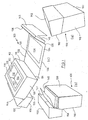
- Figure 1 illustrates a first embodiment of a package for tobacco by means of three isometric views, i.e. Figure 1(a), Figure 1(b) and Figure 1(c) .
- the package 100 comprises a box-shaped receptacle 110 having a front wall 112, a rear wall 114, a first major lateral wall 116, a second major lateral wall 117, a first minor lateral wall 118 and a second minor lateral wall 119.
- a box-shaped receptacle 110 having a front wall 112, a rear wall 114, a first major lateral wall 116, a second major lateral wall 117, a first minor lateral wall 118 and a second minor lateral wall 119.
- an access opening 120 In the front wall 112 of the receptacle 110, there is provided an access opening 120.
- the total area of the access opening 120 is smaller than the area defined by the outer edges of the front wall 112.
- the inner faces of the receptacle 110 are covered by a fresh-keeping foil 122, which extends somewhat beyond the edges of the access opening 120 such that it is visible in Figure 1(c) .
- the access opening 120 can be closed by means of a flap 130.
- the flap 130 is best seen in Figure 1(c) in which it is fully unfolded.
- the flap 130 is connected to the receptacle 110 via a hinge line 131 located at the side of the first major lateral wall 116, i.e., in the embodiment, at its common edge with the rear wall 114.
- the flap 130 comprises a first lateral panel 132, to which, via a fold line 133, a main panel 134 is connected.
- the main panel 134 has about the size of the front wall 112.
- Via another fold line 135, a second lateral panel 136 is connected to the main panel 134 of the flap 130.
- the main panel 134 is reinforced by a reinforcement structure 138 made of heavy cardboard.
- a soft sealing pad could be used instead of the reinforcement structure 138.
- a conventional cigarette paper booklet 140 comprising a foldable cover 142 and a plurality of cigarette papers is fixed to the outer side of the second lateral panel 136 of the flap 130, see Figure 1(c) .
- the package 100 includes a locking lid 150 comprising a main wall 152 as well as four side walls 154, 155, 156 and 157.
- the locking lid 150 is swivelably connected to the rear wall 114 of the receptacle 110 via a hinge line 158 located at the free edge of side wall 155.
- the distance between the hinge line 158 and the common edge between the rear wall 114 and the second major lateral wall 117 is smaller than the height of the side wall 155 (measured perpendicular to the main wall 152 of the locking lid 150).
- a cavity is formed between the main wall 152 of the locking lid 150 and the second major lateral wall 117 of the receptacle 110, when the locking lid 150 is in the closed or locked position shown in Figure 1(a) .
- the cigarette paper booklet 140 is accommodated.
- the package 100 is made from cardboard blanks which are folded and glued via tabs provided in the blanks. Other materials, like plastic materials, are conceivable as well.
- the tobacco accommodated in the receptacle 110 is kept fresh by means of the fresh-keeping foil 122.
- the fresh-keeping foil 122 is replaced by a fresh-keeping coating applied to the inner face of the receptacle 110, and instead of the cardboard reinforcement structure 138 a pad is used, which can largely seal the access opening 120 and also strengthen the package 100.
- a peelable fresh-keeping foil covering the access opening 120 of the receptacle 110 is used to provide freshness, which can also be resealable. In this case, the resealability may be accomplished by a pressure-sensitive adhesive applied to the edge area of the access opening 120.
- the closing structure consisting of the flap 130 and the locking lid 150 is in a closed position. Because of its structure comprising four side walls 154, 155, 156 and 157, the locking lid 150 firmly locks the folded flap 130 when in the closed position.
- the user can unfold the flap 130, until the package 100 assumes the final state shown in Figure 1(c) .
- the user can conveniently take tobacco from the receptacle 110 via the exposed access opening 120 and finish the rolling procedure of the cigarette.
- the folding and swivelling actions are reversed, until the initial state shown in Figure 1(a) is assumed again.
- FIG. 2 Another package for tobacco is shown in the isometric views of Figure 2 , i.e. in Figure 2(a), Figure 2(b) and Figure 2(c) .
- the package 200 comprises a receptacle 210 having a front wall 212, a rear wall 214, a first lateral wall 216, a second lateral wall 217 and a bottom wall 218. Opposite to the bottom wall 218, there is provided an access opening 220.
- the size of the access opening 220 can be increased by swivelling the front wall 212 away from the rear wall 214.
- the front wall 212 is connected to the lateral walls 216 and 217 via gusset-like extensions 222, 223 and 224, 225, respectively, see Figure 2(c) .
- the front wall 212 can be swivelled about a hinge line 226 which is located in the region of the bottom wall 218, but not exactly at an edge of the bottom wall 218, such that a fixed front panel 228 is formed.
- the hinge line for swivelling the front wall is located exactly at the bottom edge.
- a top panel 230 is foldably connected to the top edge of the front wall 212 via a hinge line 232.
- a tab 234 which protrudes to the outside and extends downwardly, i.e. to the right side in Figure 2(b) .
- the package 200 comprises a closing structure designed as a lid 240.
- the lid 240 includes a top wall 242 and a front wall 244 and is connected to the top edge of the rear wall 214 via a hinge line 246.
- two triangular lateral walls 248 and 249 are provided.
- the lid 240 of the package 200 When not used, the lid 240 of the package 200 is in the closed position shown in Figure 2(a) . In this position, the lid 240 is secured by means of the tab or claw 234 (see Figure 2(b) ), which interacts with an inner brim 250 (a back-folded flap at the inner side of the front wall 244 of the lid 240 forming an engagement edge 252, see Figure 2(c) ). The lid 240 secures the front wall 212 in its resting position shown in Figure 2(a) .
- the package for tobacco illustrated in Figure 3 is similar to that shown in Figure 2 .
- the package 300 comprises a receptacle 310 comprising a foldable front wall 312, a rear wall 314, a first lateral wall 316, a second lateral wall 317, a bottom wall 318 and an access opening 320 opposite to the bottom wall 318.
- the size of the access opening 320 can be increased by swivelling the front wall 312 away from the rear wall 314.
- gusset-like extensions 322, 323, 324 and 325 do not extend up to the upper edge of the front wall 312 and the upper edges of the first lateral wall 316 and the second lateral wall 317, respectively.
- the front wall 312 can be swivelled about a hinge line 326 at the upper edge of a fixed front panel 328, close to the bottom wall 318.
- two inserts 330 and 331 are glued to the inside of the receptacle 310 in order to increase the height of the first lateral wall 316 and the second lateral wall 317.
- the closing structure of the package 300 is formed by a lid 340, which comprises a top wall 342, a front wall 344, a' rear wall 346, a lateral wall 348 and another lateral wall 349.
- the lid 340 is swivelably connected to the receptacle 310 via a hinge line 350 located at the lower edge of the rear wall 346 of the lid 340 and the upper edge of the rear wall 314 of the receptacle 310. Because of its rigid structure and the presence of the inserts 330 and 331, the lid 340 secures itself when in its closed position, such that there is no need for a tab like tab 234 in the package of Figure 2 . However, an optional tab or another locking means can enhance the stability of the package in the closed position of the lid and can also indicate the action of opening or closing the package by a noise. General examples of suitable securing devices are discussed further above.
- the package 300 is used in the same way as the package 200.
- Figure 3(a) shows the lid 340 in its closed position. In Figure 3(b) it is partially open, and the front wall 312 is partially unfolded. In the views according to Figure 3(c) and Figure 3(d) , the front wall 312 is almost fully swivelled away from the rear wall 314, such that an easy access to the interior of the package 300 is possible.
- the packages 200 and 300 can be made from cardboard blanks, similar to the package 100. Although not explicitly shown in Figures 2 and 3 , the tobacco contained in the packages 200 and 300 can be kept fresh by means of a foil and/or a coating of the materials of the packages, similar to package 100.
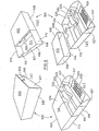
- FIG. 4 shows four isometric views of the package 400, i.e. Figure 4(a), Figure 4(b), Figure 4(c) and Figure 4(d) .
- the package 400 comprises a box-shaped receptacle 410 having a front wall 412, a rear wall 414, a first major lateral wall 416, a second major lateral wall 417, a first minor lateral wall 418 and a second minor lateral wall 419.
- An access opening 420 is arranged at the front wall 412, the area of the access opening being somewhat smaller than the total area of the front wall 412.
- the access opening 420 can be covered by a fresh-keeping foil 422.
- An edge area of the fresh-keeping foil 422 is attached to a first attachment area 424 located at the front wall 412 of the receptacle 410 close to the second major lateral wall 417, see Figure 4(c) and Figure 4(d) .
- the opposite edge of the fresh-keeping foil 422 is fixed at a second attachment area 425 located on the inside of a closing structure 430.
- the closing structure 430 comprises a front wall 432, a rear wall 434, a first minor lateral wall 438 and a second minor lateral wall 439.
- the receptacle 410 can be slid into the closing structure 430 such that a closed position is assumed, in which the closing structure 430 surrounds the receptacle 410, see Figure 4 (a) , and the fresh-keeping foil 422 covers the access opening 420.
- the closing structure 430 is moved with respect to the receptacle 410.
- Figure 4(b) shows an intermediate position. During this movement, the fresh-keeping foil 422 folds back automatically, thereby releasing the access opening 420.
- a stop structure prevents the closing structure 430 from being separated from the receptacle 410 after transfer to the opened position.
- this stop structure has been latched out in order to show the receptacle 410 and the closing structure 430 in a separated state and to permit a view at the parts of the stop structure.
- the fresh-keeping foil 422 is still connecting the receptacle 410 and the closing structure 430, whereas in Figure 4(d) , the fresh-keeping foil 422 has been removed for providing a better view.
- the stop structure comprises a tab 440 cut from the blank forming the receptacle 410 in an area of a cutout 442.
- the tab 440 interacts with a flap 444 folded back from an edge of the rear wall 434 of the closing structure 430, see in particular Figure 4(d) .
- the tab 440 grips into the flap 444, and the stop structure stops further movement when the tip of the tab 440 reaches the fold line of flap 444.
- the fresh-keeping foil 422 covers the access opening 420 and prevents the receptacle 410 from moving out of the closing structure 430 in the opposite direction.
- the closing structure 430 comprises a major lateral wall which provides a stop when the receptacle 410 is fully slid into the closed position. This major lateral wall can be provided with a cutout for pushing onto the receptacle 410 when the package 400 is to be opened.
- Figure 5 shows package which is very similar to the package of Figure 4 .
- the package 500 in Figure 5 is opened by moving the receptacle in parallel to the major lateral walls instead of in parallel to the minor lateral walls.
- package 500 comprises a receptacle 510 having a front wall 512, a rear wall 514, a first major lateral wall 516, a second major lateral wall 517, a first minor lateral wall 518 and a second minor lateral wall 519.
- An access opening 520 is automatically covered and uncovered by a fresh-keeping foil 522, fixed at a first attachment area 524 located at the front wall 512 of the receptacle 10 and at a second attachment area 525 located at the inner side of a closing structure 530, when the closing structure 530 is moved with respect to receptacle 510 to the closed position as shown in Figures 5(a) and 5(b) or the opened position, as shown in Figure 5(c) , respectively.
- the closing structure 530 comprises a front wall 532, a rear wall 534, a first major lateral wall 536 and a second major lateral wall 537. Moreover, the closing structure 530 includes a minor lateral wall 538 having a cutout zone 539, see Figure 5(b) .
- the receptacle 510 has been separated from the closing structure 530 in order to allow a view on the stop structure comprising a tab 540 formed in an optional cutout 542 of the rear wall 514 of the receptacle 510 and a flap 544 folded back at the rear wall 534 of the closing structure 530.
- the packages according to Figure 4 and Figure 5 can be folded from cardboard blanks. As before, the moisture of the loose tobacco accommodated in the packages 400 and 500 can be largely preserved by fresh-keeping foils (also inside the receptacle; not shown in the figures) or by an appropriate coating or by the choice of material for the receptacle and the closing structure.
- Figure 6 illustrates another package for tobacco, here designated by reference numeral 600.
- the basic concept of the package 600 is similar to that of package 400, but the receptacle can be slid with respect to the closing structure, in parallel to the minor lateral walls, in both directions such that two partitions of the receptacle can be exposed independent from each other.
- the package 600 comprises a receptacle 610, in which the total front wall is designed as access opening 612. Further, the receptacle 610 includes a rear wall 614, a first major lateral wall 616, a second major lateral wall 617, a first minor lateral wall 618 and a second minor lateral wall 619.
- the receptacle 610 is subdivided by a partitioning wall 620 (running in parallel to the first major lateral wall 616) into a first partition 621 and a second partition 622.
- the first partition 621 is designed to accommodate loose tobacco.
- the second partition 622 is subdivided by further partitioning walls 624 and 625 in order to store, e.g., a cigarette paper booklet and other small items a consumer likes when self-preparing cigarettes.
- the second partition 622 can also be used to accommodate prepared cigarettes.
- a holder 626 (designed with a profiled area able to clamp individual cigarettes or filter tips) is fixed to the inner side of the second major lateral wall 617.
- the second major lateral wall 617 is foldable about a hinge line located at the common edge with the rear wall 614 of the receptacle 610.
- Two side extensions 627 of the second major lateral wall 617 which have arcuate upper edges, slide between the minor lateral walls 618, 619 and respective folded-over inner parts of the minor lateral walls 618, 619.
- the partitioning wall 620 and the further partitioning walls 624, 625 may comprise rounded cutouts 628 to facilitate the access to the stored items with the consumer's fingers.
- a similar cutout 628 is provided at the first major lateral wall 616 of the receptacle 610.
- the second major lateral wall 617 comprises a pulling tab 629 which even allows to open the compartment comprising the holder 626 without moving the receptacle 610 relative to the closing structure described in the next paragraph.
- a closing structure 630 surrounds the receptacle 610, see Figure 6(a) .
- the closing structure 630 comprises a front wall 632, a rear wall 634, a first minor lateral wall 638 and a second minor lateral wall 639, but no major lateral walls.
- Figure 6(b) shows the opened position, after the receptacle 610 has been slid to one side in order to expose the first partition 621.
- Figure 6(c) the receptacle 610 has been moved into the opposite direction into a second opened position in which the items in the second partition 622 are presented to the consumer.
- a stop structure which blocks a further movement of the closing structure 630 with respect to the receptacle 610 beyond the opened position shown in Figure 6(b) and the second opened position shown in Figure 6(c) , respectively.
- the stop structure can comprise a protrusion at one or both of the minor lateral walls 618, 619 of the receptacle 610. At the end of each travel position of the receptacle 610 (i.e. when the opened position or the second opened position has been reached), this protrusion abuts at the end edge of a tab folded back from the respective side of the adjacent first or second, respectively, minor lateral wall 638, 639 of the closing structure 630.
Description
- The invention relates to a package for tobacco, in particular for loose tobacco used for self-making or rolling cigarettes.
- A conventional package for loose tobacco is designed as a soft pouch with a flap for closing the access opening of the pouch.
-
WO-A-8808602 claim 1 is based, discloses a cigarette package comprising two receptacles, which are foldable upon each other about longitudinally extending fold lines and are open at one of their respective end sides. The open end sides of both receptacles can be closed by a common lid, which is connected to one of the receptacles at a fold line running transversely with respect to the longitudinal direction. The lid also locks the package when both receptacles are folded upon each other. -
US-A-5,232,087 discloses a combination of a product transmittal package with a greeting card. A rectangular box is accessible via a tuck-in flap at one of its major lateral sides. A foldable flap covers the front wall of the box, thus covering a cutout in the front wall, and can be overlaid by another flap serving as a greeting card. When the package is used for product transmittal, the greeting card flap is secured by a zip strip, which can be opened once only. - The object of the invention is to create a package for tobacco which has an appearance or design much different from that of a conventional pouch and which can provide additional options for improving usefulness, accessibility to the tobacco and freshness.
- This object is achieved by a package for tobacco as defined in
claim 1. Advantageous versions of the invention follow from the dependent claims. - The package according to the invention comprises a receptacle and a closing structure. The receptacle is adapted to accommodate loose tobacco and includes a front wall, a rear wall, a first and a second major lateral wall opposite to each other, and a first and a second minor lateral wall opposite to each other. An access opening is provided in the front wall of the receptacle. The closing structure is moveable relative to the receptacle from a closed position, in which the closing structure closes the access opening, to an opened position, in which the access opening is accessible.
- In this context, the lateral walls generally have a smaller surface area than the front wall and the rear wall. The "major" lateral walls generally have a greater length than the "minor" lateral walls. The terms "first" and "second" are applied for definition purposes only; they could also be interchanged.
- The package according to the invention can have similar dimensions as and look similar to a conventional cigarette pack, which is much different from a pouch and provides an attractive appeal. Moreover, the hard-box character of the package provides more stability in general.
- Preferably, the area of the access opening is smaller than the area of the front wall of the receptacle. Such design improves the rigidity of the package.
- The closing structure comprises a flap, which is hingedly connected to the receptacle at the side of the first major or minor lateral wall and is foldable from a closed position, in which the flap covers the access opening, to an opened position, in which the access opening is accessible. The flap is be secured by means of a locking lid, which is hingedly connected to the receptacle at the side of the second major or minor lateral wall, i.e. generally' opposite to the connection of the flap and is swivelable from a locking position, in which it firmly locks the flap in the closed position, to an unlocking position, in which it releases the flap. Preferably, the flap and the locking lid are connected to the receptacle at the side of the first and second, respectively, major lateral wall. The term "at the side of" does not necessarily mean that a respective hinge line runs on the surface area or along an edge of the lateral wall in question, but it is to express that a respective means for a hinged connection is closer to the lateral wall in question than to the opposite lateral wall.
- In this design, the locking lid can comprise a main wall and at least one side wall emerging from an edge of the main wall. Preferably, the locking lid comprises four side walls emerging from edges of the main wall, wherein the locking lid is hingedly connected to the receptacle along a hinge line located at the free edge of one of the side walls and, preferably, at the rear wall of the receptacle. The locking lid can be connected to the receptacle such that, in the locking position of the locking lid, a cavity is provided between the main wall of the locking lid and the second major or minor lateral wall of the receptacle. This cavity may accommodate, e.g., a cigarette paper booklet, see below.
- In this design, instead of connecting the locking lid at the rear wall of the receptacle, it is also conceivable to hingedly connect the locking lid at one of the minor lateral walls (if the flap is connected to the receptacle at the side of the first major lateral wall) or at one of the major lateral walls (if the flap is connected to the receptacle at the side of the first minor lateral wall). The result is a design in which the swivel axes of the flap and the locking lid are generally perpendicular to each other (generally without crossing each other), which provides for an interesting appearance.
- Moreover, the flap can comprise a first lateral panel and a main panel, wherein the first lateral panel and the main panel are separated by a fold line (creasing line) and, when the flap is in the closed position, the first lateral panel is close to the first major or minor lateral wall of the receptacle and the main panel closes the access opening. In addition to the main panel, the flap can also comprise a second lateral panel, wherein the main panel and the second lateral panel are separated by a fold line and, when the flap is in the closed position, the main panel closes the access opening and the second lateral panel is close to the second major or minor lateral wall of the receptacle. In a very advantageous embodiment of this design, a cigarette paper booklet is attached to the second lateral panel. The flap can also comprise a sealing pad and/or a reinforcement means, which covers the access opening when the flap is in the closed position.
- A package which includes a flap and a locking lid can be designed in a very attractive manner. The package is rigid. The locking lid keeps the flap safely in the closed position but can nevertheless be easily swivelled to the unlocking position. And the package can provide extra space for cigarette paper. When the user opens the locking lid, the cigarette paper gets already accessible while the access opening of the receptacle is still closed. This is just the right order of presentation of the equipment required for rolling a cigarette.
- A locking lid without side walls or with less than four side walls is conceivable as well, in particular when the package does not include a cigarette paper booklet. In this case, the locking lid is less rigid, and an additional securing means (e.g. a self-gripping fastener, like Velcro®) may be advantageous. Other common fastener types, e.g. using a magnetic foil, are feasible as well.
- In different embodiments of the package not according to the invention, the closing structure comprises a front wall, a rear wall, a first and a second major lateral wall opposite to each other, and optionally one minor lateral wall, wherein the closing structure, in the closed position, surrounds the receptacle and wherein the closing structure, for transfer into the opened position, is slidable with respect to the receptacle. Alternatively, the closing structure comprises a front wall, a rear wall, a first and a second minor lateral wall opposite to each other, and optionally one major lateral wall, wherein the closing structure, in the closed position, surrounds the receptacle and wherein the closing structure, for transfer into the opened position, is slidable with respect to the receptacle. When the closing structure comprises the optional lateral wall, this lateral wall is preferably provided with a cutout. In these cases, the package can comprise a stop structure, which is adapted to prevent the closing structure from being separated from the receptacle after transfer to the opened position. The stop structure can include, e.g., a folded element at the receptacle and another folded element at the rear wall, front wall or a lateral wall of the surrounding closing structure, wherein one of the folded elements engages into the other one in order to limit the relative travel between the receptacle and the closing structure. The packages of this design have a rigid structure and can be used in a very intuitive manner.
- The access opening of the receptacle can be covered, in the closed position, by a fresh-keeping foil in order to keep the tobacco inside the receptacle fresh and to preserve its moistire content, at least partially. To this end, the fresh-keeping foil may be attached, at one edge, at the receptacle and, at the opposite edge, at the closing structure, such that it is automatically rolled up when the closing structure is transferred into the opened position and releases the access opening. When the package is closed, this process is reversed. A manually operated fresh-keeping foil (optionally a resealable one) is conceivable as well.
- In a variant of these embodiments, the receptacle includes a partitioning wall running essentially in parallel to the first major lateral wall and dividing the receptacle into a first and a second partition. The second partition of the receptacle can be optionally subdivided by at least one additional partitioning wall, which preferably runs in parallel to the partitioning wall already mentioned. As before, the closing structure comprises a front wall, a rear wall, and a first and a second minor lateral wall opposite to each other (but not an optional major lateral wall). In the closed position, the closing structure surrounds the receptacle. The closing structure, for transfer into the opened position, is slidable with respect to the receptacle to expose the access opening of the receptacle at the side of the first partition. Additionally, the closing structure, for transfer into a second opened position, is slidable with respect to the receptacle in the opposite direction to expose the access opening of the receptacle at the side of the second partition. Again, a stop means can be provided which limits the relative movement of the closing structure and the receptacle to either side.
- In this embodiment, the first partition can accommodate loose tobacco. It is also conceivable to place into the first partition a conventional pouch filled with tobacco. The second partition may be used for, e.g., a cigarette paper booklet, a lighter, filter tips or ready-prepared self-made cigarettes. The additional partitioning walls mentioned above can provide compartments for accommodating such items and keep them in nice order.
- The second partition can also comprise a profiled area adapted to hold at least one self-made cigarette. For example, the lateral wall of the receptacle at the side of the second partition may be designed such that it can be swivelled downwards to enhance access to the second partition, wherein the inner side of this wall comprises the profiled area to be used for storing (ordered and separated), e.g., filter tips or prepared cigarettes.
- In different variants of a package not according to the invention, a receptacle is adapted to accommodate loose tobacco and includes a front wall, a rear wall, a first and a second lateral wall opposite to each other, and a bottom wall. An access opening is provided opposite to the bottom wall, wherein the front wall is connected to foldable gusset-like (wing-like) extensions of the lateral walls and is swivelable away from the rear wall, about a hinge line in the region of the bottom wall, from a resting position to a use position for increase of the access opening. A lid includes a top wall and a front wall, wherein the lid is hingedly connected to the receptacle in the region of the rear wall of the receptacle and is swivelable from a closed position, in which the lid closes the access opening and secures the front wall of the receptacle in the resting position, to an opened position, in which the lid releases the front wall of the receptacle.
- In this context, the lateral walls and the bottom wall generally have a smaller surface area than the front wall and the rear wall. "In the region of" means "at or generally close to", but is not limited to "at".
- The package according to these variants has some remote similarity to a conventional tobacco pouch, but it is more rigid and appealing because it also comprises elements of a conventional cigarette pack.
- The lid can be hingedly connected to the receptacle along a hinge line located at an edge of the top wall of the lid, wherein the lid includes two lateral walls stabilising the front wall of the lid. Moreover, a top panel may be foldably connected to an upper edge of the front wall of the receptacle. When the lid is in its closed position, this top panel is placed opposite to the bottom wall of the receptacle. For allowing access to the interior of the receptacle, the top panel can be folded away.
- Alternatively, the lid includes a rear wall and two lateral walls connecting the rear wall of the lid to the front wall of the lid, wherein the lid is hingedly connected to the receptacle along a hinge line located at an edge of the rear wall of the lid. In this embodiment, the height of the front wall of the receptacle and/or the height of the rear wall of the receptacle can be smaller than the height of the lateral walls of the receptacle, the heights being measured perpendicular to the bottom wall of the receptacle.
- In the variants including a locking lid or a lid, a securing device adapted to secure the locking lid or lid in the locked or closed position may be advantageous. Suitable securing devices as such are well known in the art. Usually, they include a part at the locking lid or lid and a counterpart at the receptacle, for example a magnetic device (e.g. a magnetic foil interacting with a steel foil), a hook/hook device or a hook/loop device (like or similar to Velcro®), a push button device, a tab/slit device (e.g. a tab protruding at the locking lid or lid and fitting into a slit provided at the receptacle) or a claw/brim device (as further explained in one of the embodiments below). An adhesive tape, which does not require a counterpart, is suitable as well.
- Generally, a sound-producing device adapted to produce a sound when the receptacle is moved relative to the closing structure or lid provides for an interesting effect. The sound-producing device can comprise at least one tab protruding from the receptacle or from the closing structure or lid, wherein this tab interferes with a counterpart during the relative motion to produce a sound. Such tab may also aid in securing the lid in its closed position. Many variants of a securing device as explained in the previous paragraph also produce a sound when operated and can be considered as a sound-producing device as well.
- Moreover, the package according to the invention may comprise at least one bevelled or rounded edge, e.g. at the receptacle or at the closing structure. Such rounded edges can provide an appealing effect.
- In advantageous embodiments of the invention, a fresh-keeping foil (e.g., a plastic film or a laminated material or an aluminium foil) is provided in the receptacle or at the access opening of the receptacle in order to keep the tobacco fresh and to preserve its moisture content, at least partially. When the access opening is closed by a fresh-keeping foil, it may be opened manually or automatically upon access to the receptacle. In the former case, the fresh-keeping foil may be fixed at one edge of the access opening such that it can be lifted manually; as an option, a resealing means like a pressure-sensitive adhesive may be provided. An example for an automatically acting fresh-keeping foil is given further above. It is also conceivable to manufacture the receptacle from a material which has inherent fresh-keeping properties, for example from coated or laminated cardboard.
- Cardboard is a preferred material for the package according to the invention. The package or parts thereof may be cut from an appropriate blank, folded, and glued, as is well known in the art. Materials other than cardboard, e.g. plastic material or laminated material, can be used as well.
- The application of a fresh-keeping foil at the access opening of a package has already been explained above for some embodiments of the invention. Generally, it is also conceivable to provide a re-sealable fresh-keeping foil at the access opening of the receptacle (for example a foil interacting with a self-adhesive edge of the access opening), which the consumer partially peels off before taking tobacco from the receptacle and closes again when finished.
- In the following, the invention is described in more detail by means of drawings. The figures show in
- Figure 1
- isometric views of the embodiment of the package for tobacco according to the invention, i.e. in part (a) with a locking lid in a locking position, in part (b) with the locking lid in an unlocking position, and in part (c) with a flap folded to an opened position and allowing access to a receptacle,
- Figure 2
- isometric views of a second package for tobacco, i.e. in part (a) with a lid in a closed position, in part (b) with the lid partially opened, and in part (c) with the lid fully opened and releasing a front wall of a receptacle,
- Figure 3
- isometric views of a third package for tobacco, i.e. in part (a) with a lid in a closed position, in part (b) with the lid partially opened, in part (c) with the lid fully opened and releasing a front wall of a receptacle, and in part (d) as in part (c), but viewed from a different direction,
- Figure 4
- isometric views of a forth package for tobacco, i.e. in part (a) with a box-shaped receptacle slid into a closing structure into a closed position, in part (b) with the closing structure in a partially opened position, in part (c) with the receptacle moved out of the closing structure, and in part (d) as in part (c), but with a fresh-keeping foil being removed,
- Figure 5
- isometric views of a fifth package for tobacco, i.e. in part (a) with a box-shaped receptacle slid into a closing structure into a closed position, in part (b) as in part (a), but viewed from a different direction, in part (c) with the closing structure in an opened position, and in part (d) with the receptacle moved out of the closing structure, and
- Figure 6
- isometric views of a sixth package for tobacco, i.e. in part (a) with a receptacle having two partitions slid into a closing structure into a closed position, in part (b) with the closing structure exposing one of the partitions, in part (c) with the closing structure moved relative to the receptacle into the opposite direction and exposing the other partition including its sub-partitions, and in part (d) with the receptacle moved out of the closing structure.
- The packages in
Figures 2-6 are not according to the invention. -
Figure 1 illustrates a first embodiment of a package for tobacco by means of three isometric views, i.e.Figure 1(a), Figure 1(b) and Figure 1(c) . - The
package 100 comprises a box-shapedreceptacle 110 having afront wall 112, arear wall 114, a first majorlateral wall 116, a second majorlateral wall 117, a first minorlateral wall 118 and a second minorlateral wall 119. In thefront wall 112 of thereceptacle 110, there is provided anaccess opening 120. The total area of the access opening 120 is smaller than the area defined by the outer edges of thefront wall 112. - The inner faces of the
receptacle 110 are covered by a fresh-keepingfoil 122, which extends somewhat beyond the edges of the access opening 120 such that it is visible inFigure 1(c) . - The access opening 120 can be closed by means of a
flap 130. Theflap 130 is best seen inFigure 1(c) in which it is fully unfolded. - The
flap 130 is connected to thereceptacle 110 via ahinge line 131 located at the side of the first majorlateral wall 116, i.e., in the embodiment, at its common edge with therear wall 114. Theflap 130 comprises a firstlateral panel 132, to which, via afold line 133, amain panel 134 is connected. Themain panel 134 has about the size of thefront wall 112. Via anotherfold line 135, a secondlateral panel 136 is connected to themain panel 134 of theflap 130. - The
main panel 134 is reinforced by areinforcement structure 138 made of heavy cardboard. Alternatively, a soft sealing pad could be used instead of thereinforcement structure 138. - A conventional
cigarette paper booklet 140 comprising afoldable cover 142 and a plurality of cigarette papers is fixed to the outer side of the secondlateral panel 136 of theflap 130, seeFigure 1(c) . - Moreover, the
package 100 includes a lockinglid 150 comprising amain wall 152 as well as fourside walls lid 150 is swivelably connected to therear wall 114 of thereceptacle 110 via ahinge line 158 located at the free edge ofside wall 155. The distance between thehinge line 158 and the common edge between therear wall 114 and the second majorlateral wall 117 is smaller than the height of the side wall 155 (measured perpendicular to themain wall 152 of the locking lid 150). Thus, a cavity is formed between themain wall 152 of the lockinglid 150 and the second majorlateral wall 117 of thereceptacle 110, when the lockinglid 150 is in the closed or locked position shown inFigure 1(a) . In this cavity, thecigarette paper booklet 140 is accommodated. - In the embodiment, the
package 100 is made from cardboard blanks which are folded and glued via tabs provided in the blanks. Other materials, like plastic materials, are conceivable as well. As already mentioned, the tobacco accommodated in thereceptacle 110 is kept fresh by means of the fresh-keepingfoil 122. In an alternative embodiment, the fresh-keepingfoil 122 is replaced by a fresh-keeping coating applied to the inner face of thereceptacle 110, and instead of the cardboard reinforcement structure 138 a pad is used, which can largely seal the access opening 120 and also strengthen thepackage 100. Alternatively, a peelable fresh-keeping foil covering the access opening 120 of thereceptacle 110 is used to provide freshness, which can also be resealable. In this case, the resealability may be accomplished by a pressure-sensitive adhesive applied to the edge area of theaccess opening 120. - In
Figure 1(a) , the closing structure consisting of theflap 130 and the lockinglid 150 is in a closed position. Because of its structure comprising fourside walls lid 150 firmly locks the foldedflap 130 when in the closed position. - In
Figure 1(b) , the locking lid has been swivelled to an unlocking position, in which thecigarette paper booklet 140 is exposed. In that state, a user can take a single cigarette paper from thecigarette paper booklet 140 and prepare for rolling a cigarette. - In the next step, the user can unfold the
flap 130, until thepackage 100 assumes the final state shown inFigure 1(c) . Now, the user can conveniently take tobacco from thereceptacle 110 via the exposed access opening 120 and finish the rolling procedure of the cigarette. Finally, the folding and swivelling actions are reversed, until the initial state shown inFigure 1(a) is assumed again. - Another package for tobacco is shown in the isometric views of
Figure 2 , i.e. inFigure 2(a), Figure 2(b) and Figure 2(c) . - The
package 200 comprises areceptacle 210 having afront wall 212, arear wall 214, a firstlateral wall 216, a secondlateral wall 217 and abottom wall 218. Opposite to thebottom wall 218, there is provided anaccess opening 220. - The size of the access opening 220 can be increased by swivelling the
front wall 212 away from therear wall 214. To this end, thefront wall 212 is connected to thelateral walls like extensions Figure 2(c) . Thefront wall 212 can be swivelled about ahinge line 226 which is located in the region of thebottom wall 218, but not exactly at an edge of thebottom wall 218, such that a fixedfront panel 228 is formed. When thefront wall 212 is swivelled about thehinge line 226, the gusset-like extensions - Moreover, a
top panel 230 is foldably connected to the top edge of thefront wall 212 via ahinge line 232. In thefront wall 212, there is provided atab 234, which protrudes to the outside and extends downwardly, i.e. to the right side inFigure 2(b) . - The
package 200 comprises a closing structure designed as alid 240. Thelid 240 includes atop wall 242 and afront wall 244 and is connected to the top edge of therear wall 214 via ahinge line 246. For stabilizing the shape of thelid 240, two triangularlateral walls - When not used, the
lid 240 of thepackage 200 is in the closed position shown inFigure 2(a) . In this position, thelid 240 is secured by means of the tab or claw 234 (seeFigure 2(b) ), which interacts with an inner brim 250 (a back-folded flap at the inner side of thefront wall 244 of thelid 240 forming anengagement edge 252, seeFigure 2(c) ).Thelid 240 secures thefront wall 212 in its resting position shown inFigure 2(a) . - When a consumer wants to take out tobacco from the
package 200, he or she opens thelid 240, which provides a click noise when thetab 234 is released, seeFigure 2(b) . Finally, the consumer unfolds thefront wall 212, seeFigure 2(c) , such that alarge access opening 220 for easy removal of tobacco is obtained. - To close the
package 200, the actions described before are reversed. - The package for tobacco illustrated in
Figure 3 is similar to that shown inFigure 2 . - In
Figure 3 , thepackage 300 comprises areceptacle 310 comprising a foldablefront wall 312, arear wall 314, a firstlateral wall 316, a secondlateral wall 317, abottom wall 318 and an access opening 320 opposite to thebottom wall 318. - The size of the access opening 320 can be increased by swivelling the
front wall 312 away from therear wall 314. In this embodiment, gusset-like extensions front wall 312 and the upper edges of the firstlateral wall 316 and the secondlateral wall 317, respectively. Thefront wall 312 can be swivelled about ahinge line 326 at the upper edge of a fixedfront panel 328, close to thebottom wall 318. - In the package according to
Figure 3 , twoinserts receptacle 310 in order to increase the height of the firstlateral wall 316 and the secondlateral wall 317. - The closing structure of the
package 300 is formed by alid 340, which comprises atop wall 342, afront wall 344, a'rear wall 346, alateral wall 348 and anotherlateral wall 349. Thelid 340 is swivelably connected to thereceptacle 310 via ahinge line 350 located at the lower edge of therear wall 346 of thelid 340 and the upper edge of therear wall 314 of thereceptacle 310. Because of its rigid structure and the presence of theinserts lid 340 secures itself when in its closed position, such that there is no need for a tab liketab 234 in the package ofFigure 2 . However, an optional tab or another locking means can enhance the stability of the package in the closed position of the lid and can also indicate the action of opening or closing the package by a noise. General examples of suitable securing devices are discussed further above. - The
package 300 is used in the same way as thepackage 200.Figure 3(a) shows thelid 340 in its closed position. InFigure 3(b) it is partially open, and thefront wall 312 is partially unfolded. In the views according toFigure 3(c) and Figure 3(d) , thefront wall 312 is almost fully swivelled away from therear wall 314, such that an easy access to the interior of thepackage 300 is possible. - The
packages package 100. Although not explicitly shown inFigures 2 and3 , the tobacco contained in thepackages package 100. - A fourth package for tobacco is illustrated in
Figure 4 , which shows four isometric views of thepackage 400, i.e.Figure 4(a), Figure 4(b), Figure 4(c) and Figure 4(d) . - The
package 400 comprises a box-shapedreceptacle 410 having afront wall 412, arear wall 414, a first majorlateral wall 416, a second majorlateral wall 417, a first minorlateral wall 418 and a second minorlateral wall 419. An access opening 420 is arranged at thefront wall 412, the area of the access opening being somewhat smaller than the total area of thefront wall 412. - The access opening 420 can be covered by a fresh-keeping
foil 422. An edge area of the fresh-keepingfoil 422 is attached to afirst attachment area 424 located at thefront wall 412 of thereceptacle 410 close to the second majorlateral wall 417, seeFigure 4(c) and Figure 4(d) . The opposite edge of the fresh-keepingfoil 422 is fixed at asecond attachment area 425 located on the inside of aclosing structure 430. - The
closing structure 430 comprises afront wall 432, arear wall 434, a first minorlateral wall 438 and a second minorlateral wall 439. Thereceptacle 410 can be slid into theclosing structure 430 such that a closed position is assumed, in which theclosing structure 430 surrounds thereceptacle 410, seeFigure 4 (a) , and the fresh-keepingfoil 422 covers theaccess opening 420. - In order to expose the access opening 420, the
closing structure 430 is moved with respect to thereceptacle 410.Figure 4(b) shows an intermediate position. During this movement, the fresh-keepingfoil 422 folds back automatically, thereby releasing theaccess opening 420. - A stop structure prevents the
closing structure 430 from being separated from thereceptacle 410 after transfer to the opened position. InFigures 4(c) and 4(d) , this stop structure has been latched out in order to show thereceptacle 410 and theclosing structure 430 in a separated state and to permit a view at the parts of the stop structure. InFigure 4(c) , the fresh-keepingfoil 422 is still connecting thereceptacle 410 and theclosing structure 430, whereas inFigure 4(d) , the fresh-keepingfoil 422 has been removed for providing a better view. - The stop structure comprises a
tab 440 cut from the blank forming thereceptacle 410 in an area of acutout 442. Thetab 440 interacts with aflap 444 folded back from an edge of therear wall 434 of theclosing structure 430, see in particularFigure 4(d) . When thereceptacle 410 is inserted into theclosing structure 430 and is moved towards the opened position, thetab 440 grips into theflap 444, and the stop structure stops further movement when the tip of thetab 440 reaches the fold line offlap 444. - In the closed position, the fresh-keeping
foil 422 covers the access opening 420 and prevents thereceptacle 410 from moving out of theclosing structure 430 in the opposite direction. In a variant of the package shown inFigure 4 , theclosing structure 430 comprises a major lateral wall which provides a stop when thereceptacle 410 is fully slid into the closed position. This major lateral wall can be provided with a cutout for pushing onto thereceptacle 410 when thepackage 400 is to be opened. -
Figure 5 shows package which is very similar to the package ofFigure 4 . Thepackage 500 inFigure 5 , however, is opened by moving the receptacle in parallel to the major lateral walls instead of in parallel to the minor lateral walls. - To summarize,
package 500 comprises areceptacle 510 having afront wall 512, arear wall 514, a first majorlateral wall 516, a second majorlateral wall 517, a first minorlateral wall 518 and a second minorlateral wall 519. An access opening 520 is automatically covered and uncovered by a fresh-keepingfoil 522, fixed at afirst attachment area 524 located at thefront wall 512 of the receptacle 10 and at asecond attachment area 525 located at the inner side of aclosing structure 530, when theclosing structure 530 is moved with respect toreceptacle 510 to the closed position as shown inFigures 5(a) and 5(b) or the opened position, as shown inFigure 5(c) , respectively. - The
closing structure 530 comprises afront wall 532, arear wall 534, a first majorlateral wall 536 and a second majorlateral wall 537. Moreover, theclosing structure 530 includes a minorlateral wall 538 having acutout zone 539, seeFigure 5(b) . - In
Figure 5(d) , thereceptacle 510 has been separated from theclosing structure 530 in order to allow a view on the stop structure comprising atab 540 formed in anoptional cutout 542 of therear wall 514 of thereceptacle 510 and aflap 544 folded back at therear wall 534 of theclosing structure 530. The packages according toFigure 4 andFigure 5 can be folded from cardboard blanks. As before, the moisture of the loose tobacco accommodated in thepackages -
Figure 6 illustrates another package for tobacco, here designated byreference numeral 600. The basic concept of thepackage 600 is similar to that ofpackage 400, but the receptacle can be slid with respect to the closing structure, in parallel to the minor lateral walls, in both directions such that two partitions of the receptacle can be exposed independent from each other. - The
package 600 comprises areceptacle 610, in which the total front wall is designed as access opening 612. Further, thereceptacle 610 includes arear wall 614, a first majorlateral wall 616, a second majorlateral wall 617, a first minorlateral wall 618 and a second minorlateral wall 619. - The
receptacle 610 is subdivided by a partitioning wall 620 (running in parallel to the first major lateral wall 616) into afirst partition 621 and a second partition 622. Thefirst partition 621 is designed to accommodate loose tobacco. The second partition 622 is subdivided by further partitioningwalls lateral wall 617. In the embodiment, the second majorlateral wall 617 is foldable about a hinge line located at the common edge with therear wall 614 of thereceptacle 610. Twoside extensions 627 of the second majorlateral wall 617, which have arcuate upper edges, slide between the minorlateral walls lateral walls - The
partitioning wall 620 and thefurther partitioning walls cutouts 628 to facilitate the access to the stored items with the consumer's fingers. In the embodiment, asimilar cutout 628 is provided at the first majorlateral wall 616 of thereceptacle 610. The second majorlateral wall 617 comprises a pullingtab 629 which even allows to open the compartment comprising theholder 626 without moving thereceptacle 610 relative to the closing structure described in the next paragraph. - In the closed position, a
closing structure 630 surrounds thereceptacle 610, seeFigure 6(a) . Theclosing structure 630 comprises afront wall 632, arear wall 634, a first minorlateral wall 638 and a second minorlateral wall 639, but no major lateral walls. -
Figure 6(b) shows the opened position, after thereceptacle 610 has been slid to one side in order to expose thefirst partition 621. InFigure 6(c) , thereceptacle 610 has been moved into the opposite direction into a second opened position in which the items in the second partition 622 are presented to the consumer. - In the state shown in
Figure 6(d) , thereceptacle 610 has been separated from theclosing structure 630. In a variant of this package, a stop structure is provided which blocks a further movement of theclosing structure 630 with respect to thereceptacle 610 beyond the opened position shown inFigure 6(b) and the second opened position shown inFigure 6(c) , respectively. For example, the stop structure can comprise a protrusion at one or both of the minorlateral walls receptacle 610. At the end of each travel position of the receptacle 610 (i.e. when the opened position or the second opened position has been reached), this protrusion abuts at the end edge of a tab folded back from the respective side of the adjacent first or second, respectively, minorlateral wall closing structure 630. - For the embodiment according to
Figure 6 , similar materials or fresh-keeping means can be used as for the other embodiments.
Claims (15)
- A package for tobacco, comprising- a receptacle (110) adapted to accommodate loose tobacco and including a front wall (112), a rear wall (114), a first (116) and a second (117) major lateral wall opposite to each other, and a first (118) and a second (119) minor lateral wall opposite to each other, wherein an access opening (120) is provided in the front wall (112), and- a closing structure (130, 150) moveable relative to the receptacle (110) from a closed position, in which the closing structure (130, 150) closes the access opening (120), to an opened position, in which the access opening (120) is accessible,characterised in that the closing structure (130, 150) comprises- a flap (130), which is hingedly connected to the receptacle (110) at the side of the first major (116) or minor (118) lateral wall and is foldable from a closed position, in which the flap (130) covers the access opening (120), to an opened position, in which the access opening (120) is accessible, and- a locking lid (150), which is hingedly connected to the receptacle (110) and is swivelable from a locking position, in which it firmly locks the flap (130) in the closed position, to an unlocking position, in which it releases the flap (130), characterised in that the locking lid (150) is hingedly connected to the receptacle (110) at the side of the second major (117) or minor (119) lateral wall, opposite to the connection of the flap (130).
- Package according to claim 1, characterised in that the locking lid (150) comprises a main wall (152) and at least one side wall (154, 155, 156, 157) emerging from an edge of the main wall (152).
- Package according to claim 2, characterised in that the locking lid (150) comprises a main wall (152) and four side walls (154, 155, 156, 157) emerging from edges of the main wall (152), wherein the locking lid (150) is hingedly connected to the receptacle (110) along a hinge line (158) located at the free edge of one of the side walls (155) and, preferably, at the rear wall (114) of the receptacle (110).
- Package according to claim 3, characterised in that, in the locking position of the locking lid (150), a cavity is provided between the main wall (152) of the locking lid (150) and the second major (117) or minor (119) lateral wall of the receptacle (110).
- Package according to anyone of claims 1 to 4, characterised in that the flap (130) comprises a first lateral panel (132) and a main panel (134), wherein the first lateral panel (132) and the main panel (134) are separated by a fold line (133) and, when the flap (130) is in the closed position, the first lateral panel (132) is close to the first major (116) or minor (118) lateral wall of the receptacle (110) and the main panel (134) closes the access opening (120).
- Package according to anyone of claims 1 to 5, characterised in that the flap (130) comprises a main panel (134) and a second lateral panel (136), wherein the main panel (134) and the second lateral panel (136) are separated by a fold line (135) and, when the flap (130) is in the closed position, the main panel (134) closes the access opening (120) and the second lateral panel (136) is close to the second major (117) or minor (119) lateral wall of the receptacle (110).
- Package according to claim 4 and claim 6, characterised in that a cigarette paper booklet (140) is attached to the second lateral panel (136).
- Package according to anyone of claims 1 to 7, characterised in that the flap (130) comprises a sealing pad and/or a reinforcement means (138), which covers the access opening (120) when the flap (130) is in the closed position.
- Package according to anyone of claims 1 to 8, characterised in that the area of the access opening (120) is smaller than the area of the front wall (112) of the receptacle (110).
- Package according to anyone of claims 1 to 9, characterised by a securing device adapted to secure the locking lid (150) in the locked or closed position, wherein preferably the securing device comprises one of the following designs: magnetic device, hook/hook device, hook/loop device, push button device, adhesive-tape device, tab/slit device, claw/brim device.
- Package according to anyone of claims 1 to 10, characterised in that a fresh-keeping foil (122) is provided in the receptacle (110) and/or at at least a part of the access opening (120) of the receptacle (110).
- Package according to anyone of claims 1 to 11, characterised in that a re-sealable fresh-keeping foil is provided at at least a part of the access opening (120) of the receptacle (110).
- Package according to anyone of claims 1 to 12, characterised, by a sound-producing device adapted to produce a sound when the receptacle is moved relative to the closing structure or lid, wherein the sound-producing device preferably comprises at least one tab protruding from the receptacle or from the closing structure or lid, said tab being adapted to interfere with a counterpart during the relative motion to produce a sound.
- Package according to anyone of claims 1 to 13, characterised by at least one bevelled or rounded edge.
- Package according to anyone of claims 1 to 14 and filled with loose tobacco.
Priority Applications (2)
| Application Number | Priority Date | Filing Date | Title |
|---|---|---|---|
| PL13001931T PL2617663T3 (en) | 2010-08-27 | 2010-08-27 | Tobacco package |
| EP13001931.8A EP2617663B1 (en) | 2010-08-27 | 2010-08-27 | Tobacco package |
Applications Claiming Priority (2)
| Application Number | Priority Date | Filing Date | Title |
|---|---|---|---|
| EP10008951.5A EP2423128B1 (en) | 2010-08-27 | 2010-08-27 | Package for tobacco |
| EP13001931.8A EP2617663B1 (en) | 2010-08-27 | 2010-08-27 | Tobacco package |
Related Parent Applications (2)
| Application Number | Title | Priority Date | Filing Date |
|---|---|---|---|
| EP10008951.5 Division | 2010-08-27 | ||
| EP10008951.5A Division EP2423128B1 (en) | 2010-08-27 | 2010-08-27 | Package for tobacco |
Publications (2)
| Publication Number | Publication Date |
|---|---|
| EP2617663A1 EP2617663A1 (en) | 2013-07-24 |
| EP2617663B1 true EP2617663B1 (en) | 2015-01-14 |
Family
ID=42938381
Family Applications (3)
| Application Number | Title | Priority Date | Filing Date |
|---|---|---|---|
| EP13001930.0A Not-in-force EP2620379B1 (en) | 2010-08-27 | 2010-08-27 | Tobacco package |
| EP13001931.8A Not-in-force EP2617663B1 (en) | 2010-08-27 | 2010-08-27 | Tobacco package |
| EP10008951.5A Not-in-force EP2423128B1 (en) | 2010-08-27 | 2010-08-27 | Package for tobacco |
Family Applications Before (1)
| Application Number | Title | Priority Date | Filing Date |
|---|---|---|---|
| EP13001930.0A Not-in-force EP2620379B1 (en) | 2010-08-27 | 2010-08-27 | Tobacco package |
Family Applications After (1)
| Application Number | Title | Priority Date | Filing Date |
|---|---|---|---|
| EP10008951.5A Not-in-force EP2423128B1 (en) | 2010-08-27 | 2010-08-27 | Package for tobacco |
Country Status (8)
| Country | Link |
|---|---|
| EP (3) | EP2620379B1 (en) |
| JP (1) | JP5714707B2 (en) |
| CA (1) | CA2809560A1 (en) |
| ES (3) | ES2413386T3 (en) |
| HU (1) | HUE029423T2 (en) |
| NZ (1) | NZ606778A (en) |
| PL (3) | PL2423128T3 (en) |
| WO (1) | WO2012025194A1 (en) |
Families Citing this family (11)
| Publication number | Priority date | Publication date | Assignee | Title |
|---|---|---|---|---|
| GB201205243D0 (en) | 2012-03-26 | 2012-05-09 | Kraft Foods R & D Inc | Packaging and method of opening |
| GB2511559B (en) | 2013-03-07 | 2018-11-14 | Mondelez Uk R&D Ltd | Improved Packaging and Method of Forming Packaging |
| GB2511560B (en) | 2013-03-07 | 2018-11-14 | Mondelez Uk R&D Ltd | Improved Packaging and Method of Forming Packaging |
| WO2015118140A1 (en) * | 2014-02-10 | 2015-08-13 | Sanofi-Aventis Deutschland Gmbh | Package for a set of at least two components, sheet packaging material and system comprising a package and a set of at least two components |
| DE102014009283A1 (en) | 2014-03-25 | 2015-10-01 | Focke & Co. (Gmbh & Co. Kg) | A smoking article package and method and apparatus for making the same |
| ES2607849T3 (en) | 2014-08-26 | 2017-04-04 | Reemtsma Cigarettenfabriken Gmbh | Tobacco Sting Packing |
| IT201600126156A1 (en) * | 2016-12-14 | 2018-06-14 | Gd Spa | Package of smoking items with sliding opening. |
| GB2563638B (en) * | 2017-06-21 | 2020-04-15 | Barry Thomas | Cigarette paper dispenser |
| DE102018107609A1 (en) | 2018-03-29 | 2019-10-02 | Schmitt, Moritz und Junker, Jim GbR (vertretungsberechtigte Gesellschafter: Moritz Schmitt, 65934 Frankfurt und Jim Junker, 65934 Frankfurt) | Multifunctional storage device for loose tobacco |
| IT201900019748A1 (en) * | 2019-10-24 | 2021-04-24 | Gd Spa | Slide opening package for consumer products |
| WO2022090209A1 (en) * | 2020-10-27 | 2022-05-05 | Jt International Sa | Smoking articles box |
Family Cites Families (18)
| Publication number | Priority date | Publication date | Assignee | Title |
|---|---|---|---|---|
| US1683664A (en) * | 1926-12-27 | 1928-09-11 | Graham Albert Roland | Combined cigarette box and match container |
| FR693787A (en) * | 1929-04-18 | 1930-11-25 | Cardboard box or the like | |
| GB456438A (en) * | 1935-02-04 | 1935-08-06 | John Preston Murray | Improvements in containers of slide and shell type |
| US4185763A (en) * | 1975-07-04 | 1980-01-29 | General Foods, Limited | Container with overwrap |
| JPS5715135Y2 (en) * | 1977-01-28 | 1982-03-29 | ||
| FR2614720B1 (en) * | 1987-04-29 | 1992-06-26 | Widmann Horst | PACKAGING WITH APPARENT AND NON-APPARENT DOUBLE ADVERTISING EFFECT |
| CA2104178C (en) * | 1992-09-01 | 2006-02-14 | Larry Douglas Cobler | Cigarette package assembly |
| US5232087A (en) * | 1992-09-21 | 1993-08-03 | Allen Schluger | Combination product transmittal package and greeting card |
| JPH07300384A (en) * | 1994-05-09 | 1995-11-14 | Yoshinori Onohara | Match box having stick sharpening blade |
| KR100302062B1 (en) * | 1997-07-28 | 2001-11-30 | 미즈노 마사루 | Hinged Lid Pack |
| US20040217023A1 (en) * | 2003-05-02 | 2004-11-04 | Fagg Barry Smith | Cigarette package having at least one reclosable lid |
| DE212004000001U1 (en) * | 2004-02-27 | 2004-07-29 | Burger Söhne AG Burg | Tobacco products packaging |
| GB0414631D0 (en) * | 2004-06-30 | 2004-08-04 | Reckitt Benckiser Nv | Packaging for moisture sensitive material |
| JP4925751B2 (en) * | 2006-07-07 | 2012-05-09 | レンゴー株式会社 | Packaging box |
| US20080230410A1 (en) * | 2007-03-22 | 2008-09-25 | Wesley Steven Jones | Cigarette package |
| DE102007030267A1 (en) * | 2007-06-28 | 2009-01-08 | Focke & Co.(Gmbh & Co. Kg) | Pack for lumpy or granular goods |
| KR20090033281A (en) * | 2007-09-29 | 2009-04-02 | 엘지전자 주식회사 | Packaging box for mobile terminal |
| GB0812777D0 (en) * | 2008-07-14 | 2008-08-20 | Parasol Ips Limted | Re-foldable one piece box and lid |
-
2010
- 2010-08-27 EP EP13001930.0A patent/EP2620379B1/en not_active Not-in-force
- 2010-08-27 ES ES10008951T patent/ES2413386T3/en active Active
- 2010-08-27 ES ES13001931T patent/ES2531269T3/en active Active
- 2010-08-27 PL PL10008951T patent/PL2423128T3/en unknown
- 2010-08-27 EP EP13001931.8A patent/EP2617663B1/en not_active Not-in-force
- 2010-08-27 PL PL13001930.0T patent/PL2620379T3/en unknown
- 2010-08-27 PL PL13001931T patent/PL2617663T3/en unknown
- 2010-08-27 HU HUE13001930A patent/HUE029423T2/en unknown
- 2010-08-27 ES ES13001930.0T patent/ES2572529T3/en active Active
- 2010-08-27 EP EP10008951.5A patent/EP2423128B1/en not_active Not-in-force
-
2011
- 2011-08-08 WO PCT/EP2011/003967 patent/WO2012025194A1/en active Application Filing
- 2011-08-08 JP JP2013525166A patent/JP5714707B2/en not_active Expired - Fee Related
- 2011-08-08 NZ NZ606778A patent/NZ606778A/en not_active IP Right Cessation
- 2011-08-08 CA CA2809560A patent/CA2809560A1/en not_active Abandoned
Also Published As
| Publication number | Publication date |
|---|---|
| ES2413386T3 (en) | 2013-07-16 |
| HUE029423T2 (en) | 2017-02-28 |
| EP2423128A1 (en) | 2012-02-29 |
| JP5714707B2 (en) | 2015-05-07 |
| PL2423128T3 (en) | 2013-09-30 |
| ES2572529T3 (en) | 2016-06-01 |
| PL2620379T3 (en) | 2016-09-30 |
| ES2531269T3 (en) | 2015-03-12 |
| EP2620379B1 (en) | 2016-04-06 |
| JP2013540653A (en) | 2013-11-07 |
| WO2012025194A1 (en) | 2012-03-01 |
| EP2617663A1 (en) | 2013-07-24 |
| EP2620379A1 (en) | 2013-07-31 |
| EP2423128B1 (en) | 2013-04-17 |
| PL2617663T3 (en) | 2015-06-30 |
| NZ606778A (en) | 2014-12-24 |
| CA2809560A1 (en) | 2012-03-01 |
Similar Documents
| Publication | Publication Date | Title |
|---|---|---|
| EP2617663B1 (en) | Tobacco package | |
| EP1105313B1 (en) | Pack for smoking articles | |
| KR100846030B1 (en) | Box with lid | |
| KR960700644A (en) | SOFT-SIDED LUGGAGE CASE WITH INTERFITTING AND FOLDABLY SEPARATE PACKING COMPARTMENTS | |
| EP1155974A1 (en) | Pack for smoker's articles | |
| JP2018535152A (en) | Consumer goods pack | |
| JP2019517430A (en) | Container, method | |
| CN108137207B (en) | Container with inner packing | |
| WO2007070993A1 (en) | Cigarette pack. | |
| US11858720B2 (en) | Opening pack | |
| US20010006152A1 (en) | Box | |
| EP2094573B1 (en) | Pack for tobacco | |
| TWI548571B (en) | Package for tobacco related articles and method of manufacturing the package | |
| JP2018508431A (en) | Package for smoking articles, corresponding blank and method for forming such a package | |
| CN218778053U (en) | Package and blank for rod-shaped smoking articles | |
| JP3050655U (en) | Golf ball box |
Legal Events
| Date | Code | Title | Description |
|---|---|---|---|
| PUAI | Public reference made under article 153(3) epc to a published international application that has entered the european phase |
Free format text: ORIGINAL CODE: 0009012 |
|
| AC | Divisional application: reference to earlier application |
Ref document number: 2423128 Country of ref document: EP Kind code of ref document: P |
|
| AK | Designated contracting states |
Kind code of ref document: A1 Designated state(s): AL AT BE BG CH CY CZ DE DK EE ES FI FR GB GR HR HU IE IS IT LI LT LU LV MC MK MT NL NO PL PT RO SE SI SK SM TR |
|
| 17P | Request for examination filed |
Effective date: 20140123 |
|
| RBV | Designated contracting states (corrected) |
Designated state(s): AL AT BE BG CH CY CZ DE DK EE ES FI FR GB GR HR HU IE IS IT LI LT LU LV MC MK MT NL NO PL PT RO SE SI SK SM TR |
|
| GRAP | Despatch of communication of intention to grant a patent |
Free format text: ORIGINAL CODE: EPIDOSNIGR1 |
|
| INTG | Intention to grant announced |
Effective date: 20140725 |
|
| GRAS | Grant fee paid |
Free format text: ORIGINAL CODE: EPIDOSNIGR3 |
|
| GRAA | (expected) grant |
Free format text: ORIGINAL CODE: 0009210 |
|
| AC | Divisional application: reference to earlier application |
Ref document number: 2423128 Country of ref document: EP Kind code of ref document: P |
|
| AK | Designated contracting states |
Kind code of ref document: B1 Designated state(s): AL AT BE BG CH CY CZ DE DK EE ES FI FR GB GR HR HU IE IS IT LI LT LU LV MC MK MT NL NO PL PT RO SE SI SK SM TR |
|
| REG | Reference to a national code |
Ref country code: GB Ref legal event code: FG4D |
|
| REG | Reference to a national code |
Ref country code: CH Ref legal event code: EP |
|
| REG | Reference to a national code |
Ref country code: IE Ref legal event code: FG4D |
|
| REG | Reference to a national code |
Ref country code: AT Ref legal event code: REF Ref document number: 706905 Country of ref document: AT Kind code of ref document: T Effective date: 20150215 |
|
| REG | Reference to a national code |
Ref country code: DE Ref legal event code: R096 Ref document number: 602010021889 Country of ref document: DE Effective date: 20150226 |
|
| REG | Reference to a national code |
Ref country code: NL Ref legal event code: T3 |
|
| REG | Reference to a national code |
Ref country code: ES Ref legal event code: FG2A Ref document number: 2531269 Country of ref document: ES Kind code of ref document: T3 Effective date: 20150312 |
|
| REG | Reference to a national code |
Ref country code: GR Ref legal event code: EP Ref document number: 20150400513 Country of ref document: GR Effective date: 20150421 |
|
| REG | Reference to a national code |
Ref country code: NO Ref legal event code: T2 Effective date: 20150114 |
|
| REG | Reference to a national code |
Ref country code: AT Ref legal event code: MK05 Ref document number: 706905 Country of ref document: AT Kind code of ref document: T Effective date: 20150114 |
|
| REG | Reference to a national code |
Ref country code: LT Ref legal event code: MG4D |
|
| REG | Reference to a national code |
Ref country code: PL Ref legal event code: T3 |
|
| PG25 | Lapsed in a contracting state [announced via postgrant information from national office to epo] |
Ref country code: HR Free format text: LAPSE BECAUSE OF FAILURE TO SUBMIT A TRANSLATION OF THE DESCRIPTION OR TO PAY THE FEE WITHIN THE PRESCRIBED TIME-LIMIT Effective date: 20150114 Ref country code: SE Free format text: LAPSE BECAUSE OF FAILURE TO SUBMIT A TRANSLATION OF THE DESCRIPTION OR TO PAY THE FEE WITHIN THE PRESCRIBED TIME-LIMIT Effective date: 20150114 Ref country code: BG Free format text: LAPSE BECAUSE OF FAILURE TO SUBMIT A TRANSLATION OF THE DESCRIPTION OR TO PAY THE FEE WITHIN THE PRESCRIBED TIME-LIMIT Effective date: 20150414 Ref country code: LT Free format text: LAPSE BECAUSE OF FAILURE TO SUBMIT A TRANSLATION OF THE DESCRIPTION OR TO PAY THE FEE WITHIN THE PRESCRIBED TIME-LIMIT Effective date: 20150114 Ref country code: FI Free format text: LAPSE BECAUSE OF FAILURE TO SUBMIT A TRANSLATION OF THE DESCRIPTION OR TO PAY THE FEE WITHIN THE PRESCRIBED TIME-LIMIT Effective date: 20150114 |
|
| PG25 | Lapsed in a contracting state [announced via postgrant information from national office to epo] |
Ref country code: IS Free format text: LAPSE BECAUSE OF FAILURE TO SUBMIT A TRANSLATION OF THE DESCRIPTION OR TO PAY THE FEE WITHIN THE PRESCRIBED TIME-LIMIT Effective date: 20150514 Ref country code: AT Free format text: LAPSE BECAUSE OF FAILURE TO SUBMIT A TRANSLATION OF THE DESCRIPTION OR TO PAY THE FEE WITHIN THE PRESCRIBED TIME-LIMIT Effective date: 20150114 Ref country code: LV Free format text: LAPSE BECAUSE OF FAILURE TO SUBMIT A TRANSLATION OF THE DESCRIPTION OR TO PAY THE FEE WITHIN THE PRESCRIBED TIME-LIMIT Effective date: 20150114 |
|
| REG | Reference to a national code |
Ref country code: HU Ref legal event code: AG4A Ref document number: E024276 Country of ref document: HU |
|
| REG | Reference to a national code |
Ref country code: DE Ref legal event code: R097 Ref document number: 602010021889 Country of ref document: DE |
|
| PG25 | Lapsed in a contracting state [announced via postgrant information from national office to epo] |
Ref country code: SK Free format text: LAPSE BECAUSE OF FAILURE TO SUBMIT A TRANSLATION OF THE DESCRIPTION OR TO PAY THE FEE WITHIN THE PRESCRIBED TIME-LIMIT Effective date: 20150114 Ref country code: EE Free format text: LAPSE BECAUSE OF FAILURE TO SUBMIT A TRANSLATION OF THE DESCRIPTION OR TO PAY THE FEE WITHIN THE PRESCRIBED TIME-LIMIT Effective date: 20150114 Ref country code: RO Free format text: LAPSE BECAUSE OF FAILURE TO SUBMIT A TRANSLATION OF THE DESCRIPTION OR TO PAY THE FEE WITHIN THE PRESCRIBED TIME-LIMIT Effective date: 20150114 Ref country code: CZ Free format text: LAPSE BECAUSE OF FAILURE TO SUBMIT A TRANSLATION OF THE DESCRIPTION OR TO PAY THE FEE WITHIN THE PRESCRIBED TIME-LIMIT Effective date: 20150114 Ref country code: DK Free format text: LAPSE BECAUSE OF FAILURE TO SUBMIT A TRANSLATION OF THE DESCRIPTION OR TO PAY THE FEE WITHIN THE PRESCRIBED TIME-LIMIT Effective date: 20150114 |
|
| PLBE | No opposition filed within time limit |
Free format text: ORIGINAL CODE: 0009261 |
|
| STAA | Information on the status of an ep patent application or granted ep patent |
Free format text: STATUS: NO OPPOSITION FILED WITHIN TIME LIMIT |
|
| 26N | No opposition filed |
Effective date: 20151015 |
|
| PG25 | Lapsed in a contracting state [announced via postgrant information from national office to epo] |
Ref country code: IT Free format text: LAPSE BECAUSE OF FAILURE TO SUBMIT A TRANSLATION OF THE DESCRIPTION OR TO PAY THE FEE WITHIN THE PRESCRIBED TIME-LIMIT Effective date: 20150114 |
|
| PG25 | Lapsed in a contracting state [announced via postgrant information from national office to epo] |
Ref country code: SI Free format text: LAPSE BECAUSE OF FAILURE TO SUBMIT A TRANSLATION OF THE DESCRIPTION OR TO PAY THE FEE WITHIN THE PRESCRIBED TIME-LIMIT Effective date: 20150114 |
|
| PG25 | Lapsed in a contracting state [announced via postgrant information from national office to epo] |
Ref country code: MC Free format text: LAPSE BECAUSE OF FAILURE TO SUBMIT A TRANSLATION OF THE DESCRIPTION OR TO PAY THE FEE WITHIN THE PRESCRIBED TIME-LIMIT Effective date: 20150114 |
|
| REG | Reference to a national code |
Ref country code: CH Ref legal event code: PL |
|
| PG25 | Lapsed in a contracting state [announced via postgrant information from national office to epo] |
Ref country code: CH Free format text: LAPSE BECAUSE OF NON-PAYMENT OF DUE FEES Effective date: 20150831 Ref country code: LI Free format text: LAPSE BECAUSE OF NON-PAYMENT OF DUE FEES Effective date: 20150831 |
|
| PGFP | Annual fee paid to national office [announced via postgrant information from national office to epo] |
Ref country code: LU Payment date: 20160324 Year of fee payment: 7 |
|
| REG | Reference to a national code |
Ref country code: FR Ref legal event code: PLFP Year of fee payment: 7 |
|
| PGFP | Annual fee paid to national office [announced via postgrant information from national office to epo] |
Ref country code: NL Payment date: 20160721 Year of fee payment: 7 |
|
| PGFP | Annual fee paid to national office [announced via postgrant information from national office to epo] |
Ref country code: DE Payment date: 20160721 Year of fee payment: 7 Ref country code: IE Payment date: 20160721 Year of fee payment: 7 Ref country code: NO Payment date: 20160725 Year of fee payment: 7 Ref country code: GB Payment date: 20160726 Year of fee payment: 7 |
|
| PGFP | Annual fee paid to national office [announced via postgrant information from national office to epo] |
Ref country code: GR Payment date: 20160725 Year of fee payment: 7 Ref country code: FR Payment date: 20160720 Year of fee payment: 7 Ref country code: HU Payment date: 20160901 Year of fee payment: 7 |
|
| PGFP | Annual fee paid to national office [announced via postgrant information from national office to epo] |
Ref country code: ES Payment date: 20160727 Year of fee payment: 7 Ref country code: TR Payment date: 20160808 Year of fee payment: 7 Ref country code: BE Payment date: 20160720 Year of fee payment: 7 |
|
| PG25 | Lapsed in a contracting state [announced via postgrant information from national office to epo] |
Ref country code: MT Free format text: LAPSE BECAUSE OF FAILURE TO SUBMIT A TRANSLATION OF THE DESCRIPTION OR TO PAY THE FEE WITHIN THE PRESCRIBED TIME-LIMIT Effective date: 20150114 |
|
| PG25 | Lapsed in a contracting state [announced via postgrant information from national office to epo] |
Ref country code: SM Free format text: LAPSE BECAUSE OF FAILURE TO SUBMIT A TRANSLATION OF THE DESCRIPTION OR TO PAY THE FEE WITHIN THE PRESCRIBED TIME-LIMIT Effective date: 20150114 |
|
| PG25 | Lapsed in a contracting state [announced via postgrant information from national office to epo] |
Ref country code: CY Free format text: LAPSE BECAUSE OF FAILURE TO SUBMIT A TRANSLATION OF THE DESCRIPTION OR TO PAY THE FEE WITHIN THE PRESCRIBED TIME-LIMIT Effective date: 20150114 |
|
| PGFP | Annual fee paid to national office [announced via postgrant information from national office to epo] |
Ref country code: PL Payment date: 20160721 Year of fee payment: 7 |
|
| REG | Reference to a national code |
Ref country code: DE Ref legal event code: R119 Ref document number: 602010021889 Country of ref document: DE |
|
| REG | Reference to a national code |
Ref country code: NO Ref legal event code: MMEP |
|
| REG | Reference to a national code |
Ref country code: NL Ref legal event code: MM Effective date: 20170901 |
|
| GBPC | Gb: european patent ceased through non-payment of renewal fee |
Effective date: 20170827 |
|
| PG25 | Lapsed in a contracting state [announced via postgrant information from national office to epo] |
Ref country code: HU Free format text: LAPSE BECAUSE OF NON-PAYMENT OF DUE FEES Effective date: 20170828 Ref country code: NO Free format text: LAPSE BECAUSE OF NON-PAYMENT OF DUE FEES Effective date: 20170831 |
|
| REG | Reference to a national code |
Ref country code: BE Ref legal event code: FP Effective date: 20150203 Ref country code: BE Ref legal event code: MM Effective date: 20170831 |
|
| REG | Reference to a national code |
Ref country code: FR Ref legal event code: ST Effective date: 20180430 |
|
| REG | Reference to a national code |
Ref country code: IE Ref legal event code: MM4A |
|
| PG25 | Lapsed in a contracting state [announced via postgrant information from national office to epo] |
Ref country code: GR Free format text: LAPSE BECAUSE OF NON-PAYMENT OF DUE FEES Effective date: 20180305 |
|
| PG25 | Lapsed in a contracting state [announced via postgrant information from national office to epo] |
Ref country code: LU Free format text: LAPSE BECAUSE OF NON-PAYMENT OF DUE FEES Effective date: 20170827 Ref country code: PT Free format text: LAPSE BECAUSE OF FAILURE TO SUBMIT A TRANSLATION OF THE DESCRIPTION OR TO PAY THE FEE WITHIN THE PRESCRIBED TIME-LIMIT Effective date: 20150114 Ref country code: NL Free format text: LAPSE BECAUSE OF NON-PAYMENT OF DUE FEES Effective date: 20170901 Ref country code: MK Free format text: LAPSE BECAUSE OF FAILURE TO SUBMIT A TRANSLATION OF THE DESCRIPTION OR TO PAY THE FEE WITHIN THE PRESCRIBED TIME-LIMIT Effective date: 20150114 |
|
| PG25 | Lapsed in a contracting state [announced via postgrant information from national office to epo] |
Ref country code: IE Free format text: LAPSE BECAUSE OF NON-PAYMENT OF DUE FEES Effective date: 20170827 Ref country code: GB Free format text: LAPSE BECAUSE OF NON-PAYMENT OF DUE FEES Effective date: 20170827 Ref country code: DE Free format text: LAPSE BECAUSE OF NON-PAYMENT OF DUE FEES Effective date: 20180301 |
|
| PG25 | Lapsed in a contracting state [announced via postgrant information from national office to epo] |
Ref country code: FR Free format text: LAPSE BECAUSE OF NON-PAYMENT OF DUE FEES Effective date: 20170831 Ref country code: BE Free format text: LAPSE BECAUSE OF NON-PAYMENT OF DUE FEES Effective date: 20170831 |
|
| REG | Reference to a national code |
Ref country code: ES Ref legal event code: FD2A Effective date: 20181024 |
|
| PG25 | Lapsed in a contracting state [announced via postgrant information from national office to epo] |
Ref country code: AL Free format text: LAPSE BECAUSE OF FAILURE TO SUBMIT A TRANSLATION OF THE DESCRIPTION OR TO PAY THE FEE WITHIN THE PRESCRIBED TIME-LIMIT Effective date: 20150114 |
|
| PG25 | Lapsed in a contracting state [announced via postgrant information from national office to epo] |
Ref country code: ES Free format text: LAPSE BECAUSE OF NON-PAYMENT OF DUE FEES Effective date: 20170828 |
|
| PG25 | Lapsed in a contracting state [announced via postgrant information from national office to epo] |
Ref country code: PL Free format text: LAPSE BECAUSE OF NON-PAYMENT OF DUE FEES Effective date: 20170827 |
|
| PG25 | Lapsed in a contracting state [announced via postgrant information from national office to epo] |
Ref country code: TR Free format text: LAPSE BECAUSE OF NON-PAYMENT OF DUE FEES Effective date: 20170827 |
|
| P01 | Opt-out of the competence of the unified patent court (upc) registered |
Effective date: 20230517 |