EP2617043B1 - Fiber-reinforced nanoparticle-loaded thermoset polymer composite wires and cables as well as processes for their production - Google Patents
Fiber-reinforced nanoparticle-loaded thermoset polymer composite wires and cables as well as processes for their production Download PDFInfo
- Publication number
- EP2617043B1 EP2617043B1 EP11825880.5A EP11825880A EP2617043B1 EP 2617043 B1 EP2617043 B1 EP 2617043B1 EP 11825880 A EP11825880 A EP 11825880A EP 2617043 B1 EP2617043 B1 EP 2617043B1
- Authority
- EP
- European Patent Office
- Prior art keywords
- wires
- polymer composite
- wire
- stranded
- particles
- Prior art date
- Legal status (The legal status is an assumption and is not a legal conclusion. Google has not performed a legal analysis and makes no representation as to the accuracy of the status listed.)
- Not-in-force
Links
Images


Classifications
-
- D—TEXTILES; PAPER
- D02—YARNS; MECHANICAL FINISHING OF YARNS OR ROPES; WARPING OR BEAMING
- D02G—CRIMPING OR CURLING FIBRES, FILAMENTS, THREADS, OR YARNS; YARNS OR THREADS
- D02G3/00—Yarns or threads, e.g. fancy yarns; Processes or apparatus for the production thereof, not otherwise provided for
-
- H—ELECTRICITY
- H01—ELECTRIC ELEMENTS
- H01B—CABLES; CONDUCTORS; INSULATORS; SELECTION OF MATERIALS FOR THEIR CONDUCTIVE, INSULATING OR DIELECTRIC PROPERTIES
- H01B13/00—Apparatus or processes specially adapted for manufacturing conductors or cables
- H01B13/22—Sheathing; Armouring; Screening; Applying other protective layers
-
- B—PERFORMING OPERATIONS; TRANSPORTING
- B29—WORKING OF PLASTICS; WORKING OF SUBSTANCES IN A PLASTIC STATE IN GENERAL
- B29C—SHAPING OR JOINING OF PLASTICS; SHAPING OF MATERIAL IN A PLASTIC STATE, NOT OTHERWISE PROVIDED FOR; AFTER-TREATMENT OF THE SHAPED PRODUCTS, e.g. REPAIRING
- B29C70/00—Shaping composites, i.e. plastics material comprising reinforcements, fillers or preformed parts, e.g. inserts
- B29C70/02—Shaping composites, i.e. plastics material comprising reinforcements, fillers or preformed parts, e.g. inserts comprising combinations of reinforcements, e.g. non-specified reinforcements, fibrous reinforcing inserts and fillers, e.g. particulate fillers, incorporated in matrix material, forming one or more layers and with or without non-reinforced or non-filled layers
- B29C70/021—Combinations of fibrous reinforcement and non-fibrous material
- B29C70/025—Combinations of fibrous reinforcement and non-fibrous material with particular filler
-
- B—PERFORMING OPERATIONS; TRANSPORTING
- B29—WORKING OF PLASTICS; WORKING OF SUBSTANCES IN A PLASTIC STATE IN GENERAL
- B29C—SHAPING OR JOINING OF PLASTICS; SHAPING OF MATERIAL IN A PLASTIC STATE, NOT OTHERWISE PROVIDED FOR; AFTER-TREATMENT OF THE SHAPED PRODUCTS, e.g. REPAIRING
- B29C70/00—Shaping composites, i.e. plastics material comprising reinforcements, fillers or preformed parts, e.g. inserts
- B29C70/04—Shaping composites, i.e. plastics material comprising reinforcements, fillers or preformed parts, e.g. inserts comprising reinforcements only, e.g. self-reinforcing plastics
- B29C70/28—Shaping operations therefor
- B29C70/40—Shaping or impregnating by compression not applied
- B29C70/50—Shaping or impregnating by compression not applied for producing articles of indefinite length, e.g. prepregs, sheet moulding compounds [SMC] or cross moulding compounds [XMC]
- B29C70/52—Pultrusion, i.e. forming and compressing by continuously pulling through a die
- B29C70/521—Pultrusion, i.e. forming and compressing by continuously pulling through a die and impregnating the reinforcement before the die
-
- B—PERFORMING OPERATIONS; TRANSPORTING
- B29—WORKING OF PLASTICS; WORKING OF SUBSTANCES IN A PLASTIC STATE IN GENERAL
- B29D—PRODUCING PARTICULAR ARTICLES FROM PLASTICS OR FROM SUBSTANCES IN A PLASTIC STATE
- B29D99/00—Subject matter not provided for in other groups of this subclass
-
- H—ELECTRICITY
- H01—ELECTRIC ELEMENTS
- H01B—CABLES; CONDUCTORS; INSULATORS; SELECTION OF MATERIALS FOR THEIR CONDUCTIVE, INSULATING OR DIELECTRIC PROPERTIES
- H01B13/00—Apparatus or processes specially adapted for manufacturing conductors or cables
-
- H—ELECTRICITY
- H01—ELECTRIC ELEMENTS
- H01B—CABLES; CONDUCTORS; INSULATORS; SELECTION OF MATERIALS FOR THEIR CONDUCTIVE, INSULATING OR DIELECTRIC PROPERTIES
- H01B13/00—Apparatus or processes specially adapted for manufacturing conductors or cables
- H01B13/0026—Apparatus for manufacturing conducting or semi-conducting layers, e.g. deposition of metal
-
- H—ELECTRICITY
- H01—ELECTRIC ELEMENTS
- H01B—CABLES; CONDUCTORS; INSULATORS; SELECTION OF MATERIALS FOR THEIR CONDUCTIVE, INSULATING OR DIELECTRIC PROPERTIES
- H01B13/00—Apparatus or processes specially adapted for manufacturing conductors or cables
- H01B13/22—Sheathing; Armouring; Screening; Applying other protective layers
- H01B13/225—Screening coaxial cables
-
- H—ELECTRICITY
- H01—ELECTRIC ELEMENTS
- H01B—CABLES; CONDUCTORS; INSULATORS; SELECTION OF MATERIALS FOR THEIR CONDUCTIVE, INSULATING OR DIELECTRIC PROPERTIES
- H01B3/00—Insulators or insulating bodies characterised by the insulating materials; Selection of materials for their insulating or dielectric properties
- H01B3/18—Insulators or insulating bodies characterised by the insulating materials; Selection of materials for their insulating or dielectric properties mainly consisting of organic substances
- H01B3/30—Insulators or insulating bodies characterised by the insulating materials; Selection of materials for their insulating or dielectric properties mainly consisting of organic substances plastics; resins; waxes
- H01B3/40—Insulators or insulating bodies characterised by the insulating materials; Selection of materials for their insulating or dielectric properties mainly consisting of organic substances plastics; resins; waxes epoxy resins
-
- H—ELECTRICITY
- H01—ELECTRIC ELEMENTS
- H01B—CABLES; CONDUCTORS; INSULATORS; SELECTION OF MATERIALS FOR THEIR CONDUCTIVE, INSULATING OR DIELECTRIC PROPERTIES
- H01B7/00—Insulated conductors or cables characterised by their form
- H01B7/17—Protection against damage caused by external factors, e.g. sheaths or armouring
- H01B7/29—Protection against damage caused by extremes of temperature or by flame
-
- B—PERFORMING OPERATIONS; TRANSPORTING
- B29—WORKING OF PLASTICS; WORKING OF SUBSTANCES IN A PLASTIC STATE IN GENERAL
- B29K—INDEXING SCHEME ASSOCIATED WITH SUBCLASSES B29B, B29C OR B29D, RELATING TO MOULDING MATERIALS OR TO MATERIALS FOR MOULDS, REINFORCEMENTS, FILLERS OR PREFORMED PARTS, e.g. INSERTS
- B29K2105/00—Condition, form or state of moulded material or of the material to be shaped
- B29K2105/06—Condition, form or state of moulded material or of the material to be shaped containing reinforcements, fillers or inserts
- B29K2105/12—Condition, form or state of moulded material or of the material to be shaped containing reinforcements, fillers or inserts of short lengths, e.g. chopped filaments, staple fibres or bristles
- B29K2105/122—Condition, form or state of moulded material or of the material to be shaped containing reinforcements, fillers or inserts of short lengths, e.g. chopped filaments, staple fibres or bristles microfibres or nanofibers
-
- B—PERFORMING OPERATIONS; TRANSPORTING
- B29—WORKING OF PLASTICS; WORKING OF SUBSTANCES IN A PLASTIC STATE IN GENERAL
- B29K—INDEXING SCHEME ASSOCIATED WITH SUBCLASSES B29B, B29C OR B29D, RELATING TO MOULDING MATERIALS OR TO MATERIALS FOR MOULDS, REINFORCEMENTS, FILLERS OR PREFORMED PARTS, e.g. INSERTS
- B29K2105/00—Condition, form or state of moulded material or of the material to be shaped
- B29K2105/06—Condition, form or state of moulded material or of the material to be shaped containing reinforcements, fillers or inserts
- B29K2105/16—Fillers
- B29K2105/162—Nanoparticles
Definitions
- thermoset polymer composite wires including reinforcing fibers and nanoparticles, cables made using such thermoset polymer composite wires, and methods of making and using such polymer composite wires and cables.
- Cable stranding is a process in which individual wires arc combined, typically in a helical arrangement, to produce a finished cable.
- the resulting stranded cable provides greater flexibility than is available from a solid rod of equivalent cross sectional area.
- the stranded arrangement is also beneficial because the stranded cable maintains its overall round cross-sectional shape when the cable is subject to bending in handling, installation and use.
- Such stranded cables are used in a variety of applications such as hoist cables, aircraft cables, undersea marine cables and tethers, and electrical power transmission cables.
- Stranded electrical power transmission cables are typically produced from ductile metals such as steel, aluminum, or copper.
- a stranded wire core is surrounded by a stranded wire conductor layer.
- the stranded wire core could comprise ductile metal wires made from a first material such as steel, for example, and the outer power conducting layer could comprise ductile metal wires made from another material such as aluminum, for example.
- the stranded wire core may be a pre-stranded cable used as an input material to the manufacture of a larger diameter electrical power transmission cable.
- Stranded electrical power transmission cables generally may comprise as few as seven individual wires to more common constructions containing 50 or more wires.
- Such composite wire cables is provided by a metal matrix composite wire cable containing fiber-reinforced metal matrix composite wires.
- metal matrix composite wires are attractive due to their improved mechanical properties relative to ductile metal wires, but which are primarily elastic in their stress strain response.
- Some polymer composite wire cables containing fiber-reinforced polymer matrix composite wires are also known in the art, for example, the fiber-reinforced polymer matrix composite wires disclosed in U.S. Pat. Nos. 4,961,990 ; 5,126,167 ; 7,060,326 ; 7,093,416 ; 7,179,522 ; 7,438,971 : 7,683,262 ; and PCT International Pub. No. WO 97/00976 .
- US 2002/0009581 A1 relates to an epoxy resin composition for a fiber reinforced composite material.
- the epoxy resin composition comprises an epoxy resin mixture containing two or more epoxy resins, in such a manner that 100 weight parts of the epoxy resin mixture contains 40 to 79 parts of a monofunctional or bifunctional epoxy resin and 21 to 60 parts of a trifunctional or higher functional epoxy resin and that the epoxy resin mixture is 210 to 370 in epoxy equivalent weight; fine particles containing a rubber ingredient and insoluble in the epoxy resins; and a curing agent.
- the present invention relates to a method according to claim 1 and to a thermoset polymer composite wire according to claim 5. Further aspects and examples disclosed below may be utilized in the context of the present invention.
- the present disclosure describes a method comprising impregnating a multiplicity of continuous fibers with a polymer composite matrix comprising a liquid polymer precursor and a multiplicity of particles having a median diameter of one micrometer or less (i.e. nanoparticles) uniformly dispersed throughout the liquid polymer precursor, pulling the fibers impregnated with the polymer composite matrix through a die, at least partially solidify the polymer composite matrix in the die to form a continuous thermoset polymer composite wire filament, and optionally surrounding the continuous composite wire filament with a corrosion resistant sheath.
- the multiplicity of particles are nanoparticles having a median diameter no greater than 1.000 nm, 900 nm, 800 nm, 750 nm, 700 nm, 600 nm, 500 nm, 400 nm, 300 nm, 250 nm, 200 nm, 100 nm, or even 50 nm
- the multiplicity of particles comprises reactive surface-modified nanoparticles further comprising a core and a reactive surface modifying agent associated with the nanoparticle core.
- the multiplicity of nanoparticles has a median diameter no greater than 1,000 nm, 900 nm, 800 nm, 750 nm, 700 nm, 600 nm, 500 nm, 400 nm, 300 nm, 250 nm, 200 nm, 100 nm, or even 50 nm.
- the multiplicity of particles comprise no greater than 40 wt.% of the polymer composite matrix.
- the multiplicity of continuous fibers are parallel in a direction taken parallel to a longitudinal axis of the continuous composite wire filament.
- the multiplicity of continuous fibers further comprises a multiplicity of fiber surfaces, and the multiplicity of particles do not contact the multiplicity of fiber surfaces.
- the corrosion resistant sheath comprises at least one radiation cured polymer, thermoset polymer, thermoplastic polymer having a glass transition temperature of at least 145°C, fluoropolymer, tape, or a combination thereof.
- the cured liquid polymer precursor exhibits a glass transition temperature of at least 150°C.
- the cured liquid polymer precursor comprises an epoxy resin, and the multiplicity of particles comprises from 0.5 to 40 wt.% of the polymer composite matrix.
- the cured liquid polymer precursor comprises a vinyl ester resin, and the multiplicity of particles comprises from 0.5 to 40 wt.% of the polymer composite matrix.
- At least partially solidifying the polymer composite matrix in the die comprises cross-linking the liquid polymer precursor.
- thermoset polymer composite wire made according to any of the preceding methods.
- thermoset polymer composite wire comprising a multiplicity of continuous fibers embedded in a solidified polymer composite matrix and forming a continuous filament, the solidified polymer composite matrix further comprising a polymer formed by curing a polymer precursor from a liquid state and a multiplicity of particles having a median diameter of one micrometer or less (i.e. nanoparticles) and uniformly dispersed throughout the polymer composite matrix, and optionally, a corrosion resistant sheath surrounding the continuous filament.
- the multiplicity of particles comprises surface-modified particles further comprising a nanoparticle core and a reactive surface modifying agent associated with the nanoparticle core and reacted with the polymer cured from a liquid state.
- the multiplicity of nanoparticles has a median diameter no greater than 1,000 nm, 900 nm, 800 nm, 750 nm, 700 nm, 600 nm, 500 nm, 400 nm, 300 nm, 250 nm, 200 nm, 100 nm, or even 50 nm.
- the multiplicity of continuous fibers are parallel in a direction taken parallel to a longitudinal axis of the continuous composite wire filament.
- the multiplicity of continuous fibers further comprises a multiplicity of fiber surfaces, and the multiplicity of particles (i.e. nanoparticles) do not contact the multiplicity of fiber surfaces.
- the corrosion resistant sheath comprises at least one radiation cured polymer, thermoset polymer, thermoplastic polymer having a glass transition temperature of at least 145°C, fluoropolymer, tape, or a combination thereof.
- the solidified polymer composite matrix exhibits a glass transition temperature of at least 150°C.
- the polymer formed by curing a polymer precursor from a liquid state comprises at least one thermoset resin selected from an epoxy resin, a vinyl ester resin, a polyimide resin, a polyester resin, a cyanate ester resin, a phenolic resin, a bis-malcimide resin, or a combination thereof.
- the polymer formed by curing a polymer precursor from a liquid state comprises an unsaturated polyester resin.
- the solidified polymer composite matrix comprises the cured (e.g. cross-linked) liquid polymer precursor.
- the solidified polymer composite matrix comprises an epoxy resin cured with an anhydride.
- the solidified polymer composite matrix exhibits a glass transition temperature of at least 150°C.
- the cured liquid polymer precursor exhibits a glass transition temperature of at least 150°C.
- the cured liquid polymer precursor comprises an epoxy resin, and the multiplicity of particles comprises from 0.5 to 40 wt.% of the polymer composite matrix.
- the cured liquid polymer precursor comprises a vinyl ester resin, and the multiplicity of particles comprises from 0.5 to 40 wt.% of the polymer composite matrix.
- the multiplicity of continuous fibers comprises at least one fiber selected from the group consisting of aramid fibers, glass fibers, ceramic fibers, metal fibers, polymer fibers, carbon fibers, or combinations thereof. In some examples, the multiplicity of continuous fibers comprises at least 66 volume percent of the continuous filament.
- the multiplicity of particles comprises at least one surface-modifying agent associated with a surface of the particles.
- the multiplicity of particles comprises silica particles, calcite particles, or combinations thereof.
- the multiplicity of particles comprises silica particles further comprising at least one surface modifying agent covalently bonded to a surface of the silica particles.
- the multiplicity of particles comprises calcite particles further comprising a surface-modifying agent ionically associated with a surface of the calcite particles.
- the multiplicity of particles preferably has a median diameter no greater than 400 nm. In other exemplary embodiments, the multiplicity of particles preferably has a median diameter no greater than 250 nm. In certain examples, the multiplicity of particles preferably has a median diameter no greater than 100 nm. In some particular examples, the multiplicity of particles exhibits a multimodal distribution of particle diameter on a number basis. In some particular examples, the polymer composite matrix further comprises a multiplicity of filler particles having a median diameter of at least 1 micrometer.
- thermoset polymer composite wire has a cross-sectional diameter of from about 1 mm to about 2.54 cm.
- thermoset polymer composite cable comprising at least one thermoset polymer composite wire as described above.
- the cable is a stranded cable comprising a core wire defining a center longitudinal axis, a first multiplicity of wires stranded around the core wire, and a second multiplicity of wires stranded around the first multiplicity of wires.
- At least one of the core wire, the first multiplicity of wires, or the second multiplicity of wires comprises the at least one thermoset polymer composite wire as described above.
- the core wire is a thermoset polymer composite wire as described above.
- each of the core wire, the first multiplicity of wires, and the second multiplicity of wires is selected to be a thermoset polymer composite wires as described above.
- each of the multiplicity of wires in the cable is a thermoset polymer composite wire.
- the disclosure describes a helically stranded thermoset polymer composite cable comprising at least one thermoset polymer composite wire as described above, the helically stranded cable having a core comprising a core wire defining a center longitudinal axis, a first multiplicity of wires helically stranded around the core in a first lay direction at a first lay angle defined relative to the center longitudinal axis and having a first lay length, and a second multiplicity of wires helically stranded around the first multiplicity of composite wires in a second lay direction at a second lay angle defined relative to the center longitudinal axis and having a second lay length,
- the core wire is selected from the group consisting of a thermoset polymer composite wire, a thermoplastic polymer composite wire, a metal matrix composite wire, or a ductile metal wire.
- at least one of the first multiplicity of wires is selected from the group consisting of a thermoset polymer composite wire, a thermoplastic polymer composite wire, or a ductile metal wire.
- at least one of the second multiplicity of wires is selected from the group consisting of a thermoset polymer composite wire, a thermoplastic polymer composite wire, or a ductile metal wire.
- At least one of the core wire, the first multiplicity of wires, or the second multiplicity of wires comprises the at least one thermoset polymer composite wire as described above.
- the core wire is a thermoset polymer composite wire as described above.
- each of the core wire, the first multiplicity of wires, and the second multiplicity of wires is selected to be thermoset polymer composite wires as described above.
- each of the multiplicity of wires in the cable is a thermoset polymer composite wire.
- each wire has a cross-section in a direction normal to the center longitudinal axis, and the cross-sectional shape of each wire is selected from the group including circular, elliptical, and trapezoidal.
- the cross-sectional shape of each wire is circular. and the diameter of each wire is from about 1 nm to about 2.54 cm.
- each of the first multiplicity of composite wires and the second multiplicity of composite wires has a lay factor of from 10 to 150.
- the first lay direction is the same as the second lay direction.
- a relative difference between the first lay angle and the second lay angle is greater than 0° and no greater than about 4".
- the stranded cable further comprises a third multiplicity of composite wires stranded, more preferably helically stranded around the second multiplicity of composite wires in a third lay direction at a third lay angle defined relative to the center longitudinal axis and having a third lay length.
- each of the third multiplicity of composite wires has a lay factor of from 10 to 150.
- the third lay direction is the same as the second lay direction.
- a relative difference between the third lay angle and the second lay angle is greater than 0° and no greater than about 4°.
- the stranded cable further comprises a fourth multiplicity of composite wires stranded, more preferably helically stranded around the third multiplicity of composite wires in a fourth lay direction at a fourth lay angle defined relative to the center longitudinal axis and having a fourth lay length.
- each of the fourth multiplicity of composite wires has a lay factor of from 10 to 150.
- the fourth lay direction is the same as the third lay direction.
- a relative difference between the fourth lay angle and the third lay angle is greater than 0° and no greater than about 4°.
- the multiplicity of continuous fibers comprises at least one fiber selected from metal fibers, polymer fibers, carbon fibers, ceramic fibers, glass fibers, or combinations thereof.
- the at least one fiber comprises titanium, tungsten, boron, shape memory alloy, carbon, graphite, silicon carbide, aramid. poly(p-phenylene-2,6-benzobisoxazole, or combinations thereof.
- the at least one fiber comprises a ceramic fiber selected from silicon carbide, alumina, or aluminosilicate.
- the polymer composite matrix comprises a (co)polymer selected from the group including an epoxy, an ester, a vinyl ester, a polyimide, a polyester, a cyanate ester, a phenolic resin, a bis-maleimide resin, and combinations thereof.
- At least one of the composite wires is a fiber-reinforced metal matrix composite wire further comprising at least one continuous fiber in a metal matrix, optionally wherein at least a portion of the composite wires surround the at least one fiber-reinforced metal matrix composite wire.
- the at least one continuous fiber comprises a material selected from the group including ceramics, glasses, carbon, silicon carbide, boron, iron, steel, ferrous alloys, tungsten, titanium, shape memory alloy, and combinations thereof.
- the metal matrix comprises aluminum, zinc, tin, magnesium, alloys thereof, or combinations thereof.
- the metal matrix comprises aluminum
- the at least one continuous fiber comprises a ceramic fiber.
- the ceramic fiber comprises polycrystalline ⁇ -Al 2 O 3 .
- the stranded cable may further comprise a multiplicity of ductile metal wires stranded around the core wire defining the center longitudinal axis.
- at least a portion of the multiplicity of ductile metal wires is helically stranded in the first lay direction.
- at least a portion of the multiplicity of ductile metal wires is helically stranded in a second lay direction opposite to the first lay direction.
- the multiplicity of ductile metal wires is stranded about the core wire defining the center longitudinal axis in a multiplicity of radial layers surrounding the composite wires.
- each radial layer is stranded in a lay direction opposite to that of an adjoining radial layer.
- each ductile metal wire may be selected to have a cross-section in a direction normal to the center longitudinal axis, and wherein a cross-sectional shape of each ductile wire is selected from the group including circular, elliptical, trapezoidal, S-shaped, and Z-shaped.
- the multiplicity of ductile metal wires comprise at least one metal selected from the group including iron, steel, zirconium, copper, tin, cadmium, aluminum, manganese, zinc, cobalt, nickel, chromium, titanium, tungsten, vanadium, their alloys with each other, their alloys with other metals, their alloys with silicon, and combinations thereof.
- the relative difference between the first lay angle and the second lay angle is selected to be greater than 0° and no greater than about 4". In some examples, the relative difference between the first lay angle and the second lay angle is no greater than 0.5". In certain examples, the first lay length equals the second lay length.
- the disclosure describes a cable comprising a core and a conductor layer around the core, wherein the core comprises any of the foregoing stranded cables.
- the conductor layer comprises a multiplicity of stranded conductor wires.
- the disclosure describes a cable as described above used for electrical power transmission.
- the cable is selected from the group consisting of an overhead electrical power transmission cable, an underground electrical power transmission cable, and an underwater electrical power transmission cable.
- the cable is an underwater electrical power transmission cable selected from an underwater tether or an underwater umbilical.
- the disclosure describes a method of making a stranded thermoset polymer composite cable using at least one thermoset polymer composite wire as described above, optionally combined with any of the non-thermoset polymer composite wires described above.
- the method comprises helically stranding a first multiplicity of wires about a core wire defining a center longitudinal axis, wherein helical stranding of the first multiplicity of wires is carried out in a first lay direction at a first lay angle defined relative to the center longitudinal axis; and helically stranding a second multiplicity of wires around the first multiplicity of wires, wherein helical stranding of the second multiplicity of wires is carried out in the first lay direction at a second lay angle defined relative to the center longitudinal axis.
- At least one of the core wire, the first multiplicity of wires, or the second multiplicity of wires comprises the at least one thermoset polymer composite wire.
- the first multiplicity of wires and/or the second multiplicity of wires include a multiplicity of thermoplastic polymer composite wires.
- the method optionally includes heating the helically stranded first and second multiplicity of wires to a temperature sufficient to retain the helically stranded wires in a helically stranded configuration upon cooling to 25°C.
- the method includes surrounding the first and second pluralities of wires with a corrosion resistant sheath.
- the multiplicity of particles comprises surface-modified particles further comprising a nanoparticle core and a surface modifying agent associated with the nanoparticle core and reacted with the polymer cured from a liquid state.
- the relative difference between the first lay angle and the second lay angle is greater than 0° and no greater than about 4°.
- the method of making a stranded cable using any of the polymer composite wires described above further comprises stranding a multiplicity of ductile metal wires around the core wire defining the center longitudinal axis.
- the inclusion of a multiplicity of particles having a median diameter of one micrometer or less uniformly dispersed throughout the polymer composite matrix permits attainment of a higher carbon fiber volume fraction loading in the fiber-reinforced polymer composite wire, thereby increasing the compression strength, shear modulus, stiffness, and sag resistance of the wire.
- the inclusion of a multiplicity of particles having a median diameter of one micrometer or less uniformly dispersed throughout the polymer composite matrix has also been shown to decrease the coefficient of thermal expansion (CTE) and the shrinkage upon cure.
- CTE coefficient of thermal expansion
- a 25% reduction in CTE and a 37% reduction in linear shrinkage was obtained for a cured fiber-reinforced polymer composite including a multiplicity of particles having a median diameter of 500 nm or less uniformly dispersed throughout the polymer composite matrix in comparison to a control without the particles.
- Such carbon fiber-reinforced polymer composite wires arc particularly attractive for use in overhead electrical power transmission cables.
- carbon fiber-reinforced polymer composite wires may, in some cases, be produced at lower cost than conventional ceramic fiber reinforced metal matrix composite wires.
- thermoset polymer composite wire increases one or both of the flexural strength and bend strength of the thermoset polymer composite wire, and in some examples, one or both of the flexural strength and bend strength of a composite cable incorporating such a thermoset polymer composite wire. This not only improves the wire and/or cable performance, but provides significant advantages in the handling, transport, and installation of the thermoset polymer composite wires and composite cables incorporating such wires.
- the polymer matrix of the composite core is blended from a unique combination of a high glass transition temperature epoxy resin and a curative agent which makes the polymer matrix more stable at high temperatures (e.g. as high as 280°C).
- a high glass transition temperature epoxy resin e.g. T g of 240°C, 250°C, 260°C, or even higher T g
- T g high glass transition temperature epoxy resins
- the multiplicity of particles comprises surface-modified particles further comprising a nanoparticle core and a reactive surface modifying agent associated with the nanoparticle core and reacted with the polymer cured from a liquid state.
- These chemically treated particles disperse particularly well in epoxy resin liquid polymer precursor matrix materials and generally require lower pultrusion forces to pull fibers through the die during the composite wire manufacturing process. This facilitates production of thermoset polymer composite wires at higher fiber loadings, which is highly desirable to improve the strength and mechanical properties of the composite wires. This may also facilitate production of nanoparticle-loaded composite wires at higher pultrusion line speed, or at lower pultrusion pull force, in comparison to a resin system without the nanoparticles.
- the pull force required to form a thermoset polymer composite wire is reduced by at least 30% relative to the pull force required to form the same fiber-reinforced polymer composite at the same conditions but without the multiplicity of particles having a median diameter of one micrometer or less uniformly dispersed throughout the liquid polymer precursor.
- the pull force required to form the fiber-reinforced polymer composite at a line speed of at least 20% greater than a base line speed is less than the pull force required to form the same fiber-reinforced polymer composite at the base speed and without the multiplicity of particles having a median diameter of one micrometer or less uniformly dispersed throughout the liquid polymer precursor.
- thermoset polymer composite wires and cables are sized to emphasize selected features.
- nanoparticle means a particle (or plurality of particles) having a median diameter of one micrometer (1,000 nm) or less, more preferably 900 nm or less, even more preferably 800 nm or less, 750 nm or less, 700 nm or less, 600 nm or less, 500 nm or less, 400 nm or less, 300 nm or less, 250 nm or less, 200 nm or less, 150 nm or less, 100 nm or less, 75 nm or less, or even 50 nm or less.
- nanoparticle core means the interior solid portion of a surface treated nanoparticle, the outer surface of which is functionalized.
- agglomerated is descriptive of a weak association of primary particles usually held together by charge or polarity. Agglomerated nanoparticles can typically be broken down into smaller entities by, for example, shearing forces encountered during dispersion of agglomerated nanoparticles in a liquid.
- aggregated and aggregates are descriptive of a strong association of primary particles often bound together by, for example, residual chemical treatment, covalent chemical bonds, or ionic chemical bonds. Further breakdown of the aggregates into smaller entities is very difficult to achieve. Typically, aggregated nanoparticles are not broken down into smaller entities by, for example, shearing forces encountered during dispersion of the aggregated particles in a liquid.
- (co)polymer means a homopolymer or a copolymer.
- (meth)acrylate means an acrylate- or a methacrylate-functional compound.
- thermosetting polymer means a (co)polymer that is capable of undergoing chemical reaction (e.g. polymerization) to irreversibly cure induced by the action of heat or suitable actinic radiation (e.g. by exposure to ultraviolet light, visible light, infrared light, and/or electron beam (e-beam) radiation), thereby forming an infusible, insoluble, preferably cross-linked solid or semi-solid (co)polymcr matrix.
- chemical reaction e.g. polymerization
- suitable actinic radiation e.g. by exposure to ultraviolet light, visible light, infrared light, and/or electron beam (e-beam) radiation
- liquid polymer precursor refers collectively to chemically-reactive thermosetting resins and any optional reactive diluents (e.g. monomers, oligomers, pre-polymers, and the like) that are initially present in a viscous or viscoelastic liquid state and which are capable of chemically reacting (e.g. curing, polymerizing, cross-linking, and the like) to form a (co)polymer matrix.
- any optional reactive diluents e.g. monomers, oligomers, pre-polymers, and the like
- liquid polymer precursor system “liquid polymer system,” or “thermosetting liquid polymer material” all refer to the combination of the nanoparticles (which may be surface modified), the liquid polymer precursor, and any additional components, for example solvents, dispersants, hardeners, curatives, initiators, promoters, cross-linking agents, tougheners, and fillers (e.g., clay).
- additional components for example solvents, dispersants, hardeners, curatives, initiators, promoters, cross-linking agents, tougheners, and fillers (e.g., clay).
- thcrmosct refers to a liquid polymer precursor system that has at least partially undergone an irreversible curing process to change from a fusible, soluble product into a highly intractable, preferably cross-linked, solid or semi-solid form which cannot readily be molded by flow.
- ceramic means glass, crystalline ceramic, glass-ceramic, and combinations thereof.
- polycrystalline means a material having predominantly a plurality of crystalline grains in which the grain size is less than the diameter of the fiber in which the grains arc present.
- bend or "bending” when used to refer to the deformation of a wire includes two dimensional and/or three dimensional bend deformation, such as helically bending the wire during stranding.
- bend deformation this does not exclude the possibility that the wire also has deformation resulting from tensile and/or torsional forces.
- “Significant elastic bend” deformation means bend deformation which occurs when the wire is bent to a radius of curvature up to 10,000 times the radius of the wire. As applied to a circular cross section wire, this significant clastic bend deformation would impart a strain at the outer fiber of the wire of at least 0.01%.
- ductile when used to refer to the deformation of a wire, means that the wire would undergo plastic deformation during bending or under tensile loading without fracture or breakage.
- brittle when used to refer to the deformation of a wire, means that the wire will fracture during bending or under tensile loading with minimal plastic deformation.
- wire refers to matter (e.g. metal in the case of a ductile metal wire) formed into a single filament or strand.
- composite wire refers to a wire formed from a combination of materials differing in composition or form which are bound together.
- polymer composite wire refers to a composite wire comprising one or more reinforcing materials bound into a matrix including one or more (co)polymeric phases, which may comprise thermoset (co)polymers or high glass transition temperature thermoplastic (co)polymers.
- thermoplastic polymer composite wire refers to a composite wire comprising one or more reinforcing fiber materials bound into a matrix including one or more thermoplastic (co)polymeric phases, and which exhibit ductile behavior.
- thermosetting polymer composite wire refers to a composite wire including one or more reinforcing fiber materials bound into a cured matrix derived from a thermosetting liquid (co)polymcr precursor system comprising nanoparticles uniformly dispersed in an uncured liquid polymer precursor system.
- ceramic-polymer composite wire refers to a composite wire comprising one or more reinforcing ceramic fiber materials bound into a matrix including one or more (co)polymeric phases.
- metal matrix composite wire refers to a composite wire comprising one or more reinforcing fiber materials bound into a matrix including one or more metal phases, and which exhibit non-ductile behavior and are brittle.
- lay describes the manner in which the wires in a stranded layer of a helically stranded cable arc wound into a helix.
- lay direction refers to the stranding direction of the wire strands in a helically stranded layer.
- a viewer looks at the surface of the helically stranded wire layer as the cable points away from the viewer. If the wire strands appear to turn in a clockwise direction as the strands progress away from the viewer, then the cable is referred to as having a "right hand lay.” If the wire strands appear to turn in a counter-clockwise direction as the strands progress away from the viewer, then the cable is referred to as having a "left hand lay.”
- center axis and “center longitudinal axis” are used interchangeably to denote a common longitudinal axis positioned radially at the center of a multilayer helically stranded cable.
- lay angle refers to the angle, formed by a helically stranded wire, relative to the center longitudinal axis of a helically stranded cable.
- crossing angle means the relative (absolute) difference between the lay angles of adjacent wire layers of a helically stranded wire cable.
- lay length refers to the length of a helically stranded cable in which a single wire in a helically stranded layer completes one full helical revolution about the center longitudinal axis of a helically stranded cable.
- continuous fiber means a fiber having a length that is relatively infinite when compared to the average fiber diameter. Typically, this means that the fiber has an aspect ratio (i.e., ratio of the length of the fiber to the average diameter of the fiber) of at least 1 x 10 5 (in some embodiments, at least 1 x 10 6 , or even at least 1 x 10 7 ). Typically, such fibers have a length on the order of at least about 15 cm to at least several meters, and may even have lengths on the order of kilometers or more.
- thermoset polymer composite wire comprising a plurality of continuous fibers embedded in a solidified polymer composite matrix and forming a continuous filament, the solidified polymer composite matrix further comprising a polymer formed by curing a polymer precursor from a liquid state and a plurality of particles having a median diameter of one micrometer or less (i.e. nanoparticles) uniformly dispersed throughout the polymer composite matrix, and optionally, a corrosion resistant sheath (described further below) surrounding the continuous filament.
- the plurality of particles comprises surface-modified particles further comprising a nanoparticle core and a reactive surface modifying agent associated with the nanoparticle core and reacted with the liquid polymer precursor during cure.
- the plurality of continuous fibers are parallel in a direction taken parallel to a longitudinal axis of the continuous thermoset polymer composite wire.
- the plurality of continuous fibers further comprises a plurality of fiber surfaces, and the plurality of particles do not contact the plurality of fiber surfaces.
- each of the thermoset polymer composite wires is selected to be a fiber-reinforced thermoset polymer composite wire comprising at least one of a continuous fiber tow, or a continuous monofilament fiber, in a thermoset polymer matrix. In some embodiments, at least 85% (in some embodiments, at least 90%, or even at least 95%) by number of the fibers in the thermoset polymer composite wires are continuous. In some presently preferred embodiments, the thermoset polymer composite wires preferably have a tensile strain to failure of at least 0.4%, more preferably at least 0.7%.
- thermoset polymer composite wire 2 is illustrated in FIG. 1A .
- Polymer composite wire 2 comprises fibers 1 and cured liquid polymer precursor 5 containing well-dispersed (i.e. non-agglomerated) nanoparticles 3. Generally, all fibers 1 are aligned in the length direction of the wire.
- any known or desired cross-section may be produced by appropriate design of the wire forming die, as will be described further below.
- the polymer composite matrix of the thermoset polymer composite wire comprises a high temperature thermoset (co)polymer selected from an epoxy, a vinyl ester, a polyimide, a polyester, a cyanate ester, a phenolic resin, a bis-maleimide resin, a (meth)acrylate resin, and combinations thereof.
- a high temperature thermoset (co)polymer selected from an epoxy, a vinyl ester, a polyimide, a polyester, a cyanate ester, a phenolic resin, a bis-maleimide resin, a (meth)acrylate resin, and combinations thereof.
- Presently preferred high temperature thermoset (co)polymers include high glass transition temperature (T g ) epoxy resins, for example, epoxy resins having a T g of at least about 250°C, 255°C, 260°C, or even higher T g .
- the solidified polymer composite matrix comprises an epoxy resin cured with an anhydride.
- hydroxyl-terminated liquid polymers of epichlorohydrin e.g., HTE, available from the BF Goodrich Company, Avon Lake, OH
- HTE hydroxyl-terminated liquid polymers
- PPS Polyphenylene sulfide
- LCP liquid crystalline polymers
- PI polyimides
- the polymer matrix of the thermoset polymer composite wire and/or the optional corrosion resistant sheath may optionally comprise a thermoplastic (co)polymer selected from a (meth)acrylate, a polyester, a cyanate ester, polyetherether ketone (PEEK), and combinations thereof.
- a high temperature (i.e. high T g ) thermoplastic (co)polymcr is preferred, for example, thermoplastic (co)polymer having a T g of at least 140°C, 145°C, 150°C, or even higher T g .
- One suitable high temperature thermoplastic (co)polymer is PEEK, having a T g of about 145°C.
- the polymer composite matrix may additionally comprise one or more thermoplastic fluoropolymers.
- suitable thermoplastic fluoropolymers include perfluoroalkoxy copolymers (PFA), fluorinated ethylenepropylene copolymer (FEP), polytetrafluoroethylene (PTFE), ethylenetetrafluorethylene (ETFE), ethylenechlorotrifluoroethylene (ECTFE), polyvinylidene fluoride (PVDF) homopolymer and copolymer, polyvinyl fluoride (PVF), tetrafluoroethylene polymer (TFV).
- PFA perfluoroalkoxy copolymers
- FEP fluorinated ethylenepropylene copolymer
- PTFE polytetrafluoroethylene
- ETFE ethylenetetrafluorethylene
- ECTFE ethylenechlorotrifluoroethylene
- PVDF polyvinylidene fluoride
- PVDF polyvinylidene fluoride
- PVDF poly
- Suitable thermoplastic fluoropolymers may be those sold under the trade names DYNEON THV FLUOROPLASTICS, DYNEON ETFE FLUOROPLASTICS, DYNEON FEP FLUOROPLASTICS, DYNEON PFA FLUOROPLASTICS, and DYNEON PVDF FLUOROPLASTICS (all available from 3M Company, St. Paul, MN).
- the polymer composite matrix is derived by curing a liquid polymer precursor system comprising a plurality of nanoparticles dispersed in a liquid polymer precursor.
- the cured liquid polymer precursor system forms an at least partially solidified polymer composite matrix.
- the solidified polymer composite matrix comprises a cross-linked liquid polymer precursor.
- any known liquid polymer precursor may be used in practicing the various embodiments of the present disclosure.
- a curable liquid polymer precursor is preferred.
- any known curable liquid polymer precursor compatible with a pultrusion process may be used, including, e.g., epoxy liquid polymer precursors, unsaturated polyester liquid polymer precursors, and vinyl ester liquid polymer precursors.
- the liquid polymer precursor exhibits a glass transition temperature of at least about 150°C, more preferably at least about 160°C, 170°C, 180°C, 190°C, 200°C, 210°C, 220°C, 230°C, or even 240°C.
- the polymer formed by curing a liquid polymer precursor from a liquid state comprises at least one of an epoxy resin, a vinyl ester resin, a polyimide resin, a polyester resin, a cyanate ester resin, a phenolic resin, a bis-maleimide resin, a (meth)acrylate resin, or a combination thereof.
- the polymer formed by curing a polymer precursor from a liquid state comprises an unsaturated polyester resin.
- the cured liquid polymer precursor comprises a vinyl ester resin, and the plurality of particles comprises from 5 to 40 wt.% of the polymer composite matrix.
- the cured liquid polymer precursor comprises an epoxy resin.
- the cured liquid polymer precursor comprises an epoxy resin
- the plurality of particles comprises from 0.5 to 40 wt.% of the polymer composite matrix.
- Epoxy resin liquid polymer precursors are well-known in the art and comprise compounds or mixtures of compounds which contain one or more epoxy groups. The compounds can be saturated or unsaturated, aliphatic, alicylic, aromatic, or heterocyclic, or can comprise combinations thereof. In some embodiments, compounds which contain more than one epoxy group (i.e., polyepoxides) are preferred.
- Polyepoxides which can be used include, for example, both aliphatic and aromatic polyepoxides.
- Aromatic polyepoxides may be preferred for some high temperature applications, and aliphatic polyepoxides may be preferred for some electrical power transmission applications due to their low chloride content.
- the aromatic polyepoxides are compounds containing at least one aromatic ring structure, e.g. a benzene ring, and more than one epoxy group.
- Exemplary aromatic polyepoxides include the polyglycidyl ethers of polyhydric phenols (e.g., bisphenol A derivative liquid polymer precursors, epoxy cresol-novolac liquid polymer precursors, bisphenol F derivative liquid polymer precursors, epoxy phenol-novolac liquid polymer precursors), glycidyl esters of aromatic carboxylic acids, and glycidyl amines of aromatic amines.
- Exemplary epoxy liquid polymer precursors include those based on bisphenol A and bisphenol F, e.g., some of those available under the trade name EPONTM from Hexion Specialty Chemicals, Inc., Houston, Texas.
- Particularly presently preferred epoxy resin precursors include low viscosity epoxy resins with a high glass transition temperature (T g ), such as Lindoxy 190 (3,4-Epoxycyclohexylmethyl 3,4-Epoxycyclohexane Carboxylate) with Lindride LS-252V (a methyl nadic anhydride) could be used. Blends of Lindride 252V and Lindride 25K (methyl nadic anhydride) could also be used. Lindoxy 190, Lindride 25K and Lindride LS-252V are all available from Lindau Chemicals (Columbia, SC).
- the curable liquid polymer precursor may be an ethylenically-unsaturated curable liquid polymer precursor.
- an unsaturated polyester liquid polymer precursor may be used.
- the unsaturated polyester liquid polymer precursor is the condensation product of one or more carboxylic acids or derivatives thereof (e.g., anhydrides and esters) with one or more alcohols (e.g., polyhydric alcohols).
- vinyl ester liquid polymer precursors may be used.
- the term "vinyl ester resin” refers to the reaction product of epoxy liquid polymer precursors with ethylenically-unsaturated monocarboxylic acids.
- Exemplary epoxy liquid polymer precursors include bisphenol A digycidal ether (e.g., EPON 828, available from Hexion Specialty Chemicals, Columbus, Ohio).
- Exemplary monocarboxylic acids include acrylic acid and methacrylic acid.
- reaction products are acrylic or methacrylic esters, the term "vinyl ester" is used consistently in the gel coat industry. (See, e.g., Handbook of Thermoset Plastics (Second Edition), William Andrew Publishing, page 122 (1998 ).)
- (meth)acrylate liquid polymer precursors including, e.g., urethane (meth)acrylates, polyethyleneglycol (multi)(meth)acrylates, and epoxy (multi)(meth)acrylates may be used.
- the term (meth)acrylate refers to an acrylate and/or a methacrylate, i.e., ethyl (meth)acrylate refers to ethyl acrylate and/or ethyl methacrylate.
- liquid polymer precursor systems of the present disclosure also include any number of well-known additives.
- additives include hardeners, curatives, initiators, promoters, cross-linking agents, tougheners, and fillers (e.g., clay).
- fillers e.g., clay.
- the liquid polymer precursor system (liquid polymer system or thermosetting liquid polymer material) comprises a plurality of nanoparticles, which optionally may include surface modified nanoparticles as described further below.
- the plurality of nanoparticles has a median diameter no greater than 1000 nm, 900 nm, 800 nm, 750 nm, 700 nm, 600 nm 500 nm, 400 nm, 300 nm, 250 nm, 200 nm, 150 nm, 100 nm, or even 50 nm.
- the plurality of nanoparticles has a median diameter no greater than 250 nm.
- the plurality of nanoparticles has a median diameter no greater than 100 nm.
- the polymer composite matrix further comprises a plurality of filler particles having a median diameter of at least 1 micrometer.
- the nanoparticles are selected to achieve a multimodal particle size distribution.
- a multimodal distribution is distribution having two or more modes, i.e., a bimodal distribution exhibits two modes, while a trimodal distribution exhibits three modes.
- the multimodal distribution of the surface-modified nanoparticles has a first mode (as determined by TEM) having a number average particle size of between 50 and 250 nanometers (nm), inclusive.
- the average particle size of the first mode is at least 50 nm, at least 60 nm, or even at least 70 nm.
- the average particle size of the first mode (“D1") is no greater than 150 nm, e.g., no greater than 100 nm, or even no greater than 80 nm.
- the multimodal distributions of the surface-modified nanoparticles have a second mode.
- the number average diameter of the nanoparticles in the second mode is less than the average diameter of the nanoparticles in the first mode.
- the average particle size of the second mode, D2 is no greater than 50 nm, e.g., no greater than 30 nm, no greater than 20 nm, no greater than 15 nm, or even no greater than 10 nm.
- D2 is at least 3 nm, e.g., at least 5 nm, e.g., at least 10 nm, or even at least 20 nm.
- D2 is between 3 and 10 nm, inclusive.
- D2 is between 20 and 50 nm, inclusive.
- the plurality of nanoparticles comprises silica nanoparticles.
- silica nanoparticle refers to a nanoparticle having a nanoparticle core with a silica surface. This includes nanoparticle cores that are entirely silica, as well nanoparticle cores comprising other inorganic (e.g., metal oxide) or organic cores having a silica surface.
- the nanoparticle core comprises a metal oxide. Any known metal oxide may be used. Exemplary metal oxides include silica, titania, alumina, zirconia, vanadia, chromia, antimony oxide, tin oxide, zinc oxide, ceria, and mixtures thereof.
- the nanoparticle core comprises a non-metal oxide.
- silicas include those available from Nalco Chemical Company, Naperville, Illinois (for example, NALCO 1040, 1042, 1050, 1060, 2326, 2327 and 2329); Nissan Chemical America Company, Houston, Texas (e.g., SNOWTEX-ZL, SNOWTEX-OL, SNOWTEX-YL, SNOWTEX-O, SNOWTEX-N, SNOWTEX-C, SNOWTEX-20L, SNOWTEX-40, and SNOWTEX-50); and Admatechs Co., Ltd., Japan (for example, SX009-MIE, SX009-MIF, SC1050-MJM, and SCI050-MLV).
- surface modified nanoparticles comprise surface treatment agents attached to the surface of a nanoparticle core.
- the nanoparticle core is spherical.
- the nanoparticle cores are relatively uniform in primary particle size.
- the nanoparticle cores have a narrow particle size distribution.
- the nanoparticle core is fully condensed.
- the nanoparticle core is amorphous.
- the nanoparticle core is isotropic.
- the nanoparticle core is at least partially crystalline.
- the nanoparticle core is crystalline.
- the particles are non-agglomerated.
- the particles are non-aggregated in contrast to, for example, fumed or pyrogenic silica.
- surface treatment agents for silica nanoparticles are organic species having a first functional group capable of covalently chemically attaching to the surface of a nanoparticle, wherein the attached surface treatment agent alters one or more properties of the nanoparticle.
- surface treatment agents have no more than three functional groups for attaching to the nanoparticle core.
- the surface treatment agents have a low molecular weight, e.g. a weight average molecular weight less than 1000 gm/mole.
- the surface-modified nanoparticles are reactive; that is, at least one of the surface treatment agents used to surface modify the nanoparticles of the present disclosure may include a second functional group capable of reacting with one or more of the curable liquid polymer precursor(s) and/or one or more of the reactive diluent(s) of the liquid polymer precursor system.
- a second functional group capable of reacting with one or more of the curable liquid polymer precursor(s) and/or one or more of the reactive diluent(s) of the liquid polymer precursor system.
- One class of reactive surface treatment agents suitable for use with nanosilica particulates includes basic-functional silanes, for example, aminopropylsilane
- Surface treatment agents often include more than one first functional group capable of attaching to the surface of a nanoparticle.
- alkoxy groups are common first functional groups that are capable of reacting with free silanol groups on the surface of a silica nanoparticle forming a covalent bond between the surface treatment agent and the silica surface.
- Examples of surface treatment agents having multiple alkoxy groups include trialkoxy alkylsilanes (e.g., 3-(trimethoxysilyl)propyl methacrylate) and trialkoxy arylsilanes (e.g., trimethoxy phenyl silane).
- the nanoparticles comprise calcite nanoparticles.
- Calcite is the crystalline form of calcium carbonate and typically forms rhombohedral crystals.
- at least 70%, e.g., at least 75% of the calcite nanoparticle cores have an average size of less than 400 nm.
- at least 90%, in some embodiments, at least 95%, or even at least 98% of the calcite nanoparticle cores have an average size of less than 400 nm.
- the surface-treating agent for calcite nanoparticles is a surface-modifying agent including at least a binding group and a compatiblizing segment: Comp. Seg. - Binding Group; wherein "Comp. Seg.” refers to the compatiblizing segment of the surface-modifying agent.
- the compatiblizing segment is selected to improve the compatibility of the calcite nanoparticles with the curable liquid polymer precursor.
- the selection of the compatiblizing group depends on a number of factors including the nature of the curable liquid polymer precursor, the concentration of the nanoparticles, and the desired degree of compatibility.
- useful compatiblizing agents include polyalkylene oxides, e.g., polypropylene oxide, polyethylene oxide, and combinations thereof.
- the binding group bonds to the calcite, connecting the surface-modifying agent to the calcite nanoparticle core.
- the surface-modifying agents of the present disclosure are ionically bonded to (e.g., associated with) the calcite.
- Bond energies can be predicted using density functional theory calculations.
- the calculated bond energies may be at least 0.6, e.g., at least 0.7 electron volts.
- bond energies of at least 0.8, e.g., at least 0.9, or even at least 0.95 electron volts may be useful.
- the binding group comprises a phosphonic acid and/or a sulfonic acid.
- the surface-modifying agent also comprises a reactive group, i.e., a group capable of reacting with the curable liquid polymer precursor, e.g., during the curing process. This can result in the nanocalcite particle being strongly bonded into the cured liquid polymer precursor matrix and may lead to an improvement in the physical properties of the resulting cured nanocomposite.
- the reactive group is selected based on the nature of the curable liquid polymer precursor.
- the reactive group may be located on the end of the compatiblizing segment.
- One class of reactive surface treatment agents suitable for use with nanocalcite particulates includes amino-functional compounds having a binding group comprising a phosphonic acid and/or a sulfonic acid.
- a linking group is present connecting the compatiblizing segment with the binding group: Comp. Seg. - Linking Group - Binding Group.
- the surface-modifying agent comprises a polyetheramine.
- exemplary polyetheramines include those available under the trade name JEFFAMINE® available from Huntsman Corporation, The Woodlands, Texas.
- the polyether serves as a compatiblizing segment, while the amine is the linking group linking the compatiblizing segment with the binding group.
- the surface-modifying agent comprises a zwitterion, i.e., a compound carrying a net charge of zero, but which is capable of carrying a formal positive and negative charge on different atoms.
- the formal negative charge is carried by the binding group.
- the formal positive charge is carried on the nitrogen atom of an amine, e.g., an amine linking group. In such embodiments, the amine may serve as both the linking group and the reactive group.
- the liquid polymer precursor may optionally include one or more additives.
- Optional additives including for example, solvents, dispersants, hardeners, curatives, initiators, promoters, cross-linking agents, tougheners, and fillers (e.g., clay), may, in some exemplary embodiments, be used advantageously as components of the liquid polymer precursor system.
- Presently preferred additives include reactive diluents as set forth below.
- the liquid polymer precursor system may also include a reactive diluent.
- exemplary reactive diluents include styrene, alpha-methylstyrene, vinyl toluene, divinylbenzene, triallyl cyanurate, methyl methacrylate, diallyl phthalate, ethylene glycol dimethacrylate, hydroxyethyl methacrylate, hydroxyethyl acrylate, and other mono- and multi-functional (meth)acrylates.
- Reactive diluents for epoxy liquid polymer precursors include mono- and multi-functional, aliphatic and aromatic, glycidyl ethers including, e.g., some of those available under the trade name HELOXY from Hexion Specialty Chemicals, Columbus, Ohio.
- Exemplary reactive diluents include, e.g., trimethylol propane trigylcidyl ether, 1,4-butane diol diglycidyl ether, neopentyl glycol diglycidyl ether, n-butyl glycidyl ether, 2-ethylhexyl glycidyl ether, p-tertiary butyl phenyl glycidyl ether, phenyl glycidyl ether, and cyclohexane dimethanol diglycidyl ether.
- the thermoset polymer composite wires comprise at least one continuous fiber in a thermoset polymer matrix formed by curing a liquid polymer precursor system as described above.
- any fibers suitable for use in fiber-reinforced polymer composite wires may be used.
- the at least one continuous fiber comprises a metal, a polymer, ceramic, glass, carbon, and combinations thereof.
- Exemplary fibers include carbon (e.g., graphite) fibers, glass fibers, ceramic fibers, silicon carbide fibers, polyimide fibers, polyamide fibers, or polyethylene fibers.
- the fibers may comprise titanium, tungsten, boron, shape memory alloy, graphite, silicon carbide, boron, aramid, poly(p-phenylene-2,6-benzobisoxazole), and combinations thereof. Combinations of materials or fibers may also be used.
- the form of the fibers is not particularly limited. Exemplary fiber forms include unidirectional arrays of individual continuous fibers, yarn, roving, and braided constructions. Woven and non-woven mats may also be included.
- the plurality of continuous fibers comprises at least 60, more preferably at least 62, even more preferably at least 64, most preferably at least 66 volume percent of the continuous thermoset polymer composite wire filament.
- the disclosure describes a thermoset polymer composite cable comprising at least one thermoset polymer composite wire as described above.
- the cable is a stranded cable comprising a wire core defining a center longitudinal axis, a first plurality of wires stranded around the core, and a second plurality of wires stranded around the first plurality of wires.
- the cable comprises a core comprised of at least one thermoset polymer composite wire as described above.
- At least one of the core wire, the first multiplicity of wires, or the second multiplicity of wires comprises the at least one thermoset polymer composite wire as described above.
- the core wire is a thermoset polymer composite wire as described above.
- each of the core wire, the first multiplicity of wires, and the second multiplicity of wires is selected to be a thermoset polymer composite wires as described above.
- each of the multiplicity of wires in the cable is a thermoset polymer composite wire.
- the disclosure describes a helically stranded thermoset polymer composite cable comprising at least one thermoset polymer composite wire as described above, the stranded cable comprising a core wire defining a center longitudinal axis, a first plurality of wires helically stranded around the core wire in a first lay direction at a first lay angle defined relative to the center longitudinal axis and having a first lay length, and a second plurality of wires helically stranded around the first plurality of wires in a second lay direction at a second lay angle defined relative to the center longitudinal axis and having a second lay length.
- the core wire is selected from the group consisting of a thermoset polymer composite wire, a thermoplastic polymer composite wire, a metal matrix composite wire, or a ductile metal wire.
- at least one of the first multiplicity of wires is selected from the group consisting of a thermoset polymer composite wire, a thermoplastic polymer composite wire, or a ductile metal wire.
- at least one of the second multiplicity of wires is selected from the group consisting of a thermoset polymer composite wire, a thermoplastic polymer composite wire, or a ductile metal wire.
- At least one of the core wire, the first multiplicity of wires, or the second multiplicity of wires comprises the at least one thermoset polymer composite wire as described above.
- the core wire is a thermoset polymer composite wire as described above.
- each of the core wire, the first multiplicity of wires, and the second multiplicity of wires is selected to be thermoset polymer composite wires as described above.
- each of the multiplicity of wires in the cable is a thermoset polymer composite wire.
- FIG. 1B illustrates a perspective view of an exemplary stranded (which may be helically stranded as shown) thermoset polymer composite cable 10 comprising at least one thermoset polymer composite wire as described above according to an exemplary embodiment of the present disclosure.
- the stranded thermoset polymer composite cable 10 includes a core comprising a single filament core wire 2 (which may, for example, comprise one or more thermoset polymer composite wires as shown, and/or one or more thermoplastic polymer composite wires, metal matrix composite wires, and/or ductile metal wires) defining a center longitudinal axis, a first layer 20 comprising a first plurality of wires 2' (which may, for example, comprise one or more thermoset polymer composite wires as shown, and/or one or more thermoplastic polymer composite wires, metal matrix composite wires, and/or ductile metal wires) stranded around the core wire 2 in a first lay direction (clockwise is shown, corresponding to a right hand lay), and a second layer 22 comprising a second plurality of wires 2" (which may, for example, comprise one or more thermoset polymer composite wires as shown, and/or one or more thermoplastic polymer composite wires, metal matrix composite wires, and/or ductile metal wires
- a third layer 24 comprising a third plurality of wires 2'" (which may, for example, comprise one or more thermoset polymer composite wires as shown, and/or one or more thermoplastic polymer composite wires, metal matrix composite wires, and/or ductile metal wires) may be stranded around the second plurality of wires 2" in the first lay direction to form polymer composite cable 10.
- a third plurality of wires 2' which may, for example, comprise one or more thermoset polymer composite wires as shown, and/or one or more thermoplastic polymer composite wires, metal matrix composite wires, and/or ductile metal wires
- an optional fourth layer (not shown) or even more additional layers of wires (not shown in the drawings, but which may, for example, comprise one or more thermoset polymer composite wires, thermoplastic polymer composite wires, metal matrix composite wires, and/or ductile metal wires) may be stranded around the third plurality of wires 2'" in the first lay direction.
- the core wire 2 is a single thermoset polymer composite wire as shown in FIG. 1B , although in other embodiments, the core wire 2 may be a single thermoplastic polymer composite wire, a single metal matrix composite wire, or a single ductile metal wire. In certain exemplary embodiments, all of the wires (2, 2', 2", 2"'; which may, for example, comprise one or more thermoset polymer composite wires, thermoplastic polymer composite wires, metal matrix composite wires, and/or ductile metal wires) in the first (20), second (22), third (24), fourth or higher layers may be selected to be the same or different within each layer and/or between adjacent layers.
- thermoset polymer composite wires e.g., 2', 2", 2"', and the like
- thermoset polymer composite wires may be stranded (in some embodiments helically stranded) about the single center thermoset polymer composite wire 2 defining a center longitudinal axis, such that each successive layer of thermoset polymer composite wires is wound in the same lay direction as each preceding layer of thermoset polymer composite wires.
- FIG. 1B for each layer (20, 22, and 24
- a left hand lay may alternatively be used for each layer (20, 22, 24, and the like), as shown for the exemplary stranded thermoset polymer composite cable illustrated by FIG. 1C .
- FIG. 1C illustrates a perspective view of a stranded (which may be helically stranded as shown) thermoset polymer composite cable 10' comprising at least one thermoset polymer composite wire according to one alternative exemplary embodiment of the present disclosure.
- the stranded thermoset polymer composite cable 10' includes a core comprising a core wire 2 (which may, for example, be a thermoset polymer composite wire as shown, and/or one or more thermoplastic polymer composite wire, a metal matrix composite wire, or a ductile metal wire) defining a center longitudinal axis, a first layer 20 comprising a first plurality of wires 2' stranded around the core wire 2 in a first lay direction (counter-clockwise is shown, corresponding to a left hand lay), a second layer 23 comprising a second plurality of wires 2" (which may, for example, comprise one or more thermoset polymer composite wires as shown, and/or one or more thermoplastic polymer composite wires, metal matrix composite wires,
- an optional fourth layer (not shown in the drawings, but which may, for example comprise thermoset polymer composite wires, thermoplastic polymer composite wires, metal matrix composite wires, or ductile metal wires) may be stranded around the third plurality of wires 2'" in the second lay direction.
- thermoset polymer composite wires e.g., 2' and 2
- other wires e.g., 2"', which may, for example, comprise thermoplastic polymer composite wires, metal matrix composite wires, and/or ductile metal wires
- thermoset polymer composite wires e.g., 2' and 2
- other wires e.g., 2"', which may, for example, comprise thermoplastic polymer composite wires, metal matrix composite wires, and/or ductile metal wires
- FIG. 1B a center longitudinal axis
- the core wire 2 is selected to be a single thermoset polymer composite wire, although in other embodiments, the core wire 2 may be a single non-thermoset polymer composite wire, such as, for example, a thermoplastic polymer composite wire, a metal matrix composite wire, and/or a ductile metal wire.
- the first lay direction is preferably the same as the second lay direction
- the third lay direction is preferably the same as the second lay direction
- the fourth lay direction may the same as the third lay direction
- any outer layer lay direction is preferably the same as the adjacent inner layer lay direction.
- the first lay direction may be opposite the second lay direction
- the third lay direction may be opposite the second lay direction
- the fourth lay direction may be opposite the third lay direction
- any outer layer lay direction may be opposite the adjacent inner layer lay direction.
- the relative difference between the first lay angle and the second lay angle is preferably greater than 0° and no greater than about 4°
- the relative difference between the third lay angle and the second lay angle is preferably greater than 0° and no greater than about 4°
- the relative difference between the fourth lay angle and the third lay angle is preferably greater than 0° and no greater than about 4°
- any inner layer lay angle and the adjacent outer layer lay angle is preferably greater than 0° and no greater than about 4°, more preferably no greater than 3°, most preferably no greater than 0.5°.
- one or more of the first lay length is preferably less than or equal to the second lay length
- the second lay length is preferably less than or equal to the third lay length
- the fourth lay length is preferably less than or equal to an immediately subsequent lay length
- each succeeding lay length is preferably less than or equal to the immediately preceding lay length.
- one or more of the first lay length equals the second lay length
- the second lay length equals the third lay length
- the third lay length equals the fourth lay length.
- the stranded thermoset polymer composite cable may further comprise additional (e.g., subsequent) layers (e.g., a fourth, fifth, or additional subsequent layers) of wires (which may, for example, comprise one or more thermoset polymer composite wires, thermoplastic polymer composite wires, metal matrix composite wires, and/or ductile metal wires) stranded (preferably helically stranded) around the third plurality of wires 2"' (which may, for example, comprise one or more thermoset polymer composite wires, thermoplastic polymer composite wires, metal matrix composite wires, and/or ductile metal wires).
- additional (e.g., subsequent) layers e.g., a fourth, fifth, or additional subsequent layers) of wires (which may, for example, comprise one or more thermoset polymer composite wires, thermoplastic polymer composite wires, metal matrix composite wires, and/or ductile metal wires) stranded (preferably helically stranded) around the third plurality of wires
- Helical stranding is preferably carried out in the first lay direction at a lay angle (not shown in the Figures) defined relative to the common longitudinal axis, wherein the wires in each layer have a characteristic lay length (not shown in the Figures), further wherein the relative difference between the third lay angle and the fourth or subsequent lay angle is greater than 0° and no greater than about 4°.
- stranded wires may make use of one or more (or even all) thermoset polymer composite wires in each layer.
- Such stranded wires generally have a cross-sectional dimension (e.g. a diameter for wires having a circular cross section) from about 0.5 mm to about 40 mm.
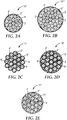
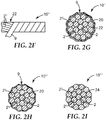
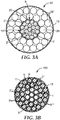
- FIGs. 2A-2I Various configurations of stranded (preferably helically stranded) composite cables including at least one thermoset polymer composite wire as described above are further illustrated by cross-sectional views in FIGs. 2A-2I . These exemplary embodiments are intended to be illustrative only; additional configurations are within the scope of this disclosure. In each of the illustrated embodiments of FIGs.
- the wires (e.g., 2, 2', 2", 2"') selected to comprise the at least one thermoset polymer composite wire, may include any number (or no) thermoplastic polymer composite wires, metal matrix composite wires, and/or ductile metal wires) stranded in a lay direction (not shown) about the core wire 2 (which may, for example, comprise the at least one thermoset polymer composite wires, thermoplastic polymer composite wires, metal matrix composite wires, and/or ductile metal wires) defining a center longitudinal axis (not shown).
- Such lay direction may be clockwise (right hand lay) or counter-clockwise (left hand lay). Furthermore, such lay direction may be the same for each succeeding layer of stranded wires, as shown in FIGs. 1B-1C , or may alternate to the opposite lay direction in each succeeding layer of stranded wires (not shown in the Figures). It is further understood that each layer of stranded wires exhibits a lay length (not shown in FIGs. 2A-2I ), and that the lay length of each layer of wires may be different, or preferably, the same lay length.
- FIG. 2A illustrates a cross-sectional view of an exemplary stranded (preferably helically stranded) composite cable 10" comprising a core wire 2 (shown as a thermoset polymer composite wire, but which alternatively may be a thermoplastic polymer composite wire, a metal matrix composite wire, or a metal wire) defining a center longitudinal axis, a plurality of wires 2' (shown as a thermoset polymer composite wire, but which alternatively may be a thermoplastic polymer composite wire, a metal matrix composite wire, or a metal wire) stranded (preferably helically stranded) around the core wire 2, and a second plurality of wires 2" (shown as a thermoset polymer composite wire, but which alternatively may be a thermoplastic polymer composite wire, a metal matrix composite wire, or a metal wire) stranded (preferably helically stranded) around the first plurality of wires 2'.
- An optional corrosion resistant sheath 9 (de
- FIG. 2B illustrates a cross-sectional view of another exemplary stranded (preferably helically stranded) composite cable 10'" as shown in FIG. 1A , the cable comprising a core wire 2 (shown as a thermoset polymer composite wire, but which alternatively may be a non-thermoset polymer composite wire, for example, a thermoplastic polymer composite wire, a metal matrix composite wire, or a metal wire) defining a center longitudinal axis, a first plurality of wires 2' (shown as a thermoset polymer composite wire, but which alternatively may be a non-thermoset polymer composite wire, for example, a thermoplastic polymer composite wire, a metal matrix composite wire, or a metal wire) stranded (preferably helically stranded) around the core wire 2, a second plurality of wires 2" (shown as a thermoset polymer composite wire, but which alternatively may be a non-thermoset polymer composite wire, for example, a thermo
- FIG. 2C illustrates a cross-sectional view of an additional exemplary stranded (preferably helically stranded) composite cable 11 including a core wire 2 (shown as a thermoset polymer composite wire, but which alternatively may be a thermoplastic polymer composite wire, a metal matrix composite wire, or a metal wire) defining a center longitudinal axis, a first plurality of wires 2' (shown as a thermoset polymer composite wire, but which alternatively may be a thermoplastic polymer composite wire, a metal matrix composite wire, or a metal wire) stranded (preferably helically stranded) around the core wire 2, a second plurality of wires 2" (shown as a thermoset polymer composite wire, but which alternatively may be a thermoplastic polymer composite wire, a metal matrix composite wire, or a metal wire) stranded (preferably helically stranded) around the first plurality of wires 2', a third plurality of wires 2'" (show
- FIG. 2D illustrates a cross-sectional view of an exemplary alternative configuration of a stranded (preferably helically stranded) composite cable 11' including a core wire 2 (shown as a thermoset polymer composite wire, but which alternatively may be a non-thermoset polymer composite wire, for example, a thermoplastic polymer composite wire, a metal matrix composite wire, or a metal wire) defining a center longitudinal axis, a first plurality of wires 2' (shown as thermoset polymer composite wires, but which alternatively may be non-thermoset polymer composite wires, for example, thermoplastic polymer composite wires, metal matrix composite wires, or metal wires) stranded (preferably helically stranded) around the core wire 2, a second plurality of wires 2" (shown as thermoset polymer composite wires, but which alternatively may be non-thermoset polymer composite wires, for example, thermoplastic polymer composite wires, metal matrix composite wires, or metal wires
- An optional corrosion resistant sheath 9, 9', 9" surrounds the plurality of wires by surrounding each individual wire.
- an optional armor element 15 (which may also be insulative and/or corrosion resistant) surrounds the entirety of the plurality of wires.
- An optional corrosion resistant and/or insulative filler material 13 may also be included to fill any voids between the wires.
- FIG. 2E illustrates a cross-sectional view of another exemplary alternative configuration of a helically stranded thermoset polymer composite cable 11" including a core wire 2 (shown as a thermoset polymer composite wire, but which alternatively may be a non-thermoset polymer composite wire, for example, a thermoplastic polymer composite wire, a metal matrix composite wire, or a metal wire) defining a center longitudinal axis, a first plurality of wires 2' (shown as a thermoset polymer composite wire, but which alternatively may be a non-thermoset polymer composite wire, for example, a thermoplastic polymer composite wire, a metal matrix composite wire, or a metal wire) stranded (preferably helically stranded) around the core wire 2, a second plurality of wires 2" (shown as a thermoset polymer composite wire, but which alternatively may be a thermoplastic polymer composite wire, a metal matrix composite wire, or a metal wire) stranded (preferably
- At least one of the core wire, the first multiplicity of wires, or the second multiplicity of wires comprises the at least one thermoset polymer composite wire as described above.
- at least the core wire 2 may be selected to be a thermoset polymer composite wire.
- FIGs. 2A-2E each show a core wire 2 defining a center longitudinal axis (not shown) which is a thermoset polymer composite wire, it is additionally understood that core wire 2 may alternatively be a thermoplastic polymer composite wire, a metal matrix composite wire, or a metal wire.
- each of the core wire, the first multiplicity of wires, and the second multiplicity of wires is selected to be a thermoset polymer composite wires as described above.
- each of the multiplicity of wires in the cable is a thermoset polymer composite wire.
- each of the wires may have a cross-sectional shape, in a direction normal to the center longitudinal axis, generally circular, elliptical, or trapezoidal.
- each of the wires has a cross-sectional shape that is generally circular, and the diameter of each polymer composite wire is at least about 0.1 mm, more preferably at least 0.5 mm; yet more preferably at least 1 mm, still more preferably at least 2 mm, most preferably at least 3 mm; and at most about 15 mm, more preferably at most 10 mm, still more preferably at most 5 mm, even more preferably at most 4 mm, most preferably at most 3 mm.
- the diameter of each thermoplastic polymer composite wire may be less than 1 mm, or greater than 5 mm.
- the average diameter of the core wire is in a range from about 0.1 mm to about 2.54 cm.
- the average cross-sectional diameter of the core wire is desirably is at least about 0.1 mm, at least 0.5 mm, at least 1 mm, at least 2 mm, at least 3 mm, at least 4 mm, or even up to about 5 mm.
- the average diameter of the single central wire is less than about 0.5 mm, less than 1 mm, less than 3 mm, less than 5 mm, less than 10 mm, less than 15 mm, less than 20 mm, or less than about 25 mm.
- the stranded thermoset polymer composite cable may include more than three stranded layers of wires about the core wire defining a center longitudinal axis.
- each of the wires in each layer of the stranded thermoset polymer composite cable may be of the same construction (preferably thermoset polymer composite wires) and shape; however this is not required in order to achieve the benefits described herein.
- Exemplary embodiments of the present disclosure preferably provide very long stranded thermoset polymer composite cables. It is also preferable that any composite wires within the stranded thermoset polymer composite cable themselves are continuous throughout the length of the stranded cable. In one preferred embodiment, the thermoset polymer composite wires are continuous and at least 150 meters long. More preferably, the thermoset polymer composite wires are continuous and at least 250 meters long, more preferably at least 500 meters, still more preferably at least 750 meters, and most preferably at least 1000 meters long in the stranded thermoset polymer composite cable.
- a corrosion resistant sheath or tape (9, 9', 9" in FIGs. 2C-2D ) may optionally be applied around each individual wire in the thermoset polymer composite cable, or around each individual 27 thermoset polymer composite wire in the cable.
- a corrosion resistant sheath surrounds at least one thermoset polymer composite wire.
- a corrosion resistant sheath surrounding the thermoset polymer composite wire is preferred for thermoset polymer composite wires which comprise carbon fibers, particularly in thermoset polymer composite cable constructions incorporating metal matrix composite wires and/or ductile metal wires. While not wishing to be bound by any particular theory, we believe that undesirable electrochemical reactions which can lead to corrosion of wires used in the thermoset polymer composite cable may be prevented or reduced by incorporating a corrosion resistant sheath surrounding the thermoset polymer composite wires.
- the corrosion resistant sheath comprises at least one radiation cured polymer, thermoset polymer, thermoplastic polymer having a glass transition temperature of at least 145°C or a fluoropolymer, a tape, a fibrous material (e.g. fiberglass mat or roving), or a combination thereof (see e.g. 9, 20, 22, and 24 in FIG. 2G ; 9 and 20 in FIG. 2H ).
- the corrosion resistant sheath may also be insulative (i.e. electrically insulative and/or thermally and/or acoustically insulative).
- the thermoset polymer composite cable may further include an optional armor element (see e.g. 15 in FIG. 2D ) to improve crush or puncture resistance of the thermoset polymer composite cable.
- the optional armor element 15 may also be insulative and/or corrosion resistant.
- the corrosion resistant sheath may surround each individual thermoset polymer composite wire (see e.g. 9, 9' and 9" in FIGs. 2C-2D ), may surround a plurality of thermoset polymer composite wires forming a layer (see e.g. 9 in FIG. 2B ), may surround the entire plurality of thermoset polymer composite wires forming a core (see e.g. 9 in FIGs. 2A-2B ), or all of the above (see e.g. 9', 9" and combined corrosion resistant sheath and armor layer 15 in FIG. 2D ).
- a corrosion resistant sheath or tape may optionally be applied around a cable core containing only thermoset polymer composite wires, or between any suitable layer containing only thermoset polymer composite wires, and any adjoining layer of wires as is desired.
- the corrosion resistant sheath (9, 9', 9", and 9""
- provides a protective layer surrounding an underlying wire core cable see e.g. 10" and 10'" in FIGs. 2A-2B , 11' and 11" in FIGs. 2D-2E , 10", 10'" and 10"” in FIGs. 2F-2I , and 10'" in 3A).
- the protective outer layer may, for example, improve puncture resistance, improve corrosion resistance, improve resistance to extremes of high or low temperature, improve friction resistance, and the like.
- FIG. 2F is a side view of an exemplary stranded thermoset polymer composite cable 10", with a corrosion resistant sheath 9 applied around the outer layer 22 of the outer layer of stranded thermoset polymer composite wires 2".
- the corrosion resistant sheath 9 may be a tape with an adhesive layer 22 on a backing 20 covering one or more layers of thermoset polymer composite wires 2, 2' and 2".
- Suitable adhesives for adhesive layer 22 include, for example, (meth)acrylate (co)polymer based adhesives, poly( ⁇ -olefin) adhesives, block copolymer based adhesives, natural rubber based adhesives, silicone based adhesives, and hot melt adhesives. Pressure sensitive adhesives may be preferred in certain embodiments.
- Suitable materials for backing 20 include polymer films, including polyester; polyimide; fluoropolymer films (including those comprising fully and partially fluorinated (co)polymers), glass reinforced backings; and combinations thereof; provided the tape is strong enough to maintain the elastic bend deformation and is capable of retaining its wrapped configuration by itself, or is sufficiently restrained if necessary.
- the tape may comprise only a backing 20 without an adhesive covering one or more layers of thermoset polymer composite wires 2, 2' and 2".
- the tape acts as a corrosion resistant sheath 9, and may also act as an electrically insulating layer surrounding the stranded composite wires 2, 2' and 2" making up the stranded thermoset polymer composite cable 10"'.
- FIG. 2I illustrates another alternative exemplary embodiment of a stranded thermoset polymer composite cable 10"" with a corrosion resistant sheath in the form of a binder 24 applied to the wires (e.g. 2, 2', and 2") in their stranded arrangement.
- binder 24 may also act as an electrically insulating sheath surrounding the stranded wires.
- the binder 24 may optionally be applied around each individual wire, or between any suitable layer of thermoset composite wires and other wires (e.g. thermoplastic polymer composite wires, metal matrix composite wires, and/or ductile metal wires) as is desired.
- Suitable binders 24 include pressure sensitive adhesive compositions comprising one or more poly (alphaolefin) homopolymers, copolymers, terpolymers, and tetrapolymers derived from monomers containing 6 to 20 carbon atoms and photoactive cross-linking agents as described in U.S. Pat. No. 5,112,882 (Babu et al. ). Radiation curing of these materials provides adhesive films having an advantageous balance of peel and shear adhesive properties.
- the binder 24 may comprise thermoset materials, including but not limited to epoxies.
- thermoset materials including but not limited to epoxies.
- the binder 24 can be applied in the form of an adhesive supplied as a transfer tape. In this case, the binder 24 is applied to a transfer or release sheet (not shown). The release sheet is wrapped around the composite wires of the stranded composite cable 10"". The backing is then removed, leaving the adhesive layer behind as the binder 24.
- thermoset polymer composite cable may suggest certain corrosion resistant sheath materials are better suited for the application.
- the binder 24 or the tape 20 without an adhesive 22 could be advantageously selected so as to not adversely affect the electrical power transmission properties of the cable at the temperatures, depths, and other conditions experienced in this application.
- an adhesive tape 20 is used as the corrosion resistant sheath 9
- both the adhesive 22 and the backing should be selected to be suitable for the intended application.
- the corrosion resistant sheath 9 is a tape (which may be an adhesive tape comprising an adhesive 22 coated on a backing 20, or just a backing 20) that is preferably wrapped such that each successive wrap overlaps, or at least abuts, the previous wrap without a gap, as is illustrated in FIG. 2F .
- the tape is wrapped such that each wrap overlaps the preceding wrap by approximately 1/3 to 1/2 of the tape width.
- successive wraps may be spaced so as to leave a gap between each wrap.
- the corrosion resistant sheath 9 may be applied to the stranded cable with conventional tape wrapping apparatus as is known in the art. Suitable taping machines include those available from Watson Machine, International, Patterson, NJ, such as model number CT-300 Concentric Taping Head.
- the tape overwrap station is generally located at the exit of the cable stranding apparatus and is applied to the helically stranded composite wires prior to the cable 10 being wound onto a take up spool.
- the corrosion resistant sheath 9 may also be selected so as to maintain the stranded arrangement of elastically deformed composite wires if such wires are included in the stranded cable 10", 10"' or 10"".
- thermoset polymer composite cable may be used advantageously as a core cable in constructing a larger diameter cable, for example, a power transmission cable 90.
- a stranded thermoset polymer composite cable 90 may comprise a first plurality of ductile metal wires 28 stranded around a tape-wrapped sheath (9) surrounding a plurality of thermoset polymer composite wires (2, 2', 2") forming a thermoset polymer composite wire core 10"'.
- a second plurality of ductile metal wires 28' is shown stranded around the first plurality of ductile metal wires 28.
- the tape is shown as a backing 20 (but alternatively may be an adhesive 22 on a backing 20) wrapped around the thermoset polymer composite wire core 10'", which includes a single thermoset polymer composite wire 2 defining a center longitudinal axis, a first layer comprising a first plurality of thermoset polymer composite wires 2', which may be stranded (preferably helically) around the single thermoset polymer composite wire 2 in a first lay direction, and a second layer comprising a second plurality of thermoset polymer composite wires 2" which may be stranded (preferably helically) around the first plurality of thermoset polymer composite wires 2' in the first lay direction.
- Tape 20 forms a corrosion resistant sheath 9, which is optionally also electrically insulating, surrounding the plurality of thermoset polymer composite wires (e.g., 2, 2', 2") comprising the core (10'").
- an armor element 15 which may also be corrosion resistant and/or electrically insulating, surrounds both the plurality of composite wires (e.g., 2, 2' and 2") and the plurality of ductile metal wires (e.g. 28 and 28").
- the corrosion resistant sheath docs not significantly add to the total diameter of the thermoset polymer composite cable.
- the thickness of the corrosion resistant sheath is no more than 10% of the outer diameter of the thermoset polymer composite cable or core which it surrounds, more preferably no more than 5%, and most preferably no more than 2% or even 1%; and at least 0.1%. more preferably at least 0.2%, even more preferably at least 0.3% or even 0.5% of the outer diameter of the thermoset polymer composite cable or core which it surrounds.
- thermoset polymer composite cable 100 may include one or more layers comprising a plurality of individually insulated thermoset polymer composite wires (2", 2'") stranded about a core comprising a plurality of individually insulated wires (1, 5), and an optional additional (or alternative) corrosion resistant armored sheath 15 surrounding the entirety of the plurality of thermoset polymer composite wires (2", 2'").
- the insulated thermoset polymer composite cable 100 includes a single core wire 1 (shown as ductile metal wire, but which may alternatively be a thermoset polymer composite wire, a thermoplastic polymer composite wire, a metal matrix composite wire, or an optical fiber wire as described further below) defining a center longitudinal axis.
- a first wire layer surrounds the single core wire 1, shown as comprising a first plurality of ductile metal wires 5 as described below (which optionally may be stranded, more preferably helically stranded around the single core wire 1 in a first lay direction).
- a second wire layer shown as comprising a first plurality of thermoset polymer composite wires 2" (which optionally may be stranded, more preferably helically stranded around the single core wire 1 in a first lay direction) is shown surrounding the first plurality of ductile metal wires 5.
- thermoset polymer composite wires 2' which optionally may be stranded, more preferably helically stranded around the first plurality of thermoset polymer composite wires 2" in the first lay direction
- An optional armor clement 15 (which may be corrosion resistant and/or insulative) is shown surrounding the entirety of the plurality of thermoset polymer composite wires (2", 2'"), and an additional optional insulative sheath (9, 9', 9", 9"') is shown surrounding each individual wire (1, 5, 2", 2"').
- FIG. 3B illustrates use of an optional insulative filler 11 (which may be a binder as described above, or which may be an insulative material, such as a non-electrically conductive solid or liquid) to fill any voids left between the individual wires (1, 5, 2", 2"') and the optional armor element 15 surrounding the entirety of the plurality of wires.
- an optional insulative filler 11 which may be a binder as described above, or which may be an insulative material, such as a non-electrically conductive solid or liquid
- the corrosion resistant sheath comprises a thermoplastic polymeric material, preferably comprising a thermoplastic polymer of a glass transition temperature of at least about 100°C, more preferably at least about 120°C, 130°C, 145°C, or even 150°C or higher.
- the thermoplastic polymeric material is selected from high density polyolefins (e.g. high density polyethylene), medium density polyolefins (e.g. medium density polyethylene), and/or thermoplastic fluoropolymers, which are presently preferred.
- thermoplastic fluoropolymers include fluorinated ethylenepropylene copolymer (FEP), polytetrafluoroethylene (PTFE), ethylenetetrafluorethylene (ETFE), ethylenechlorotrifluoroethylene (ECTFE), polyvinylidene fluoride (PVDF), polyvinyl fluoride (PVF), tetrafluoroethylene polymer (TFV).
- FEP fluorinated ethylenepropylene copolymer
- PTFE polytetrafluoroethylene
- ETFE ethylenetetrafluorethylene
- ECTFE ethylenechlorotrifluoroethylene
- PVDF polyvinylidene fluoride
- PVF polyvinyl fluoride
- TFV tetrafluoroethylene polymer
- thermoplastic fluoropolymers are those sold under the trade names DYNEON THV FLUOROPLASTICS, DYNEON ETFE FLUOROPLASTICS, DYNEON FEP FLUOROPLASTICS, DYNEON PFA FLUOROPLASTICS, and DYNEON PVDF FLUOROPLASTICS (all available from 3M Company, St. Paul, MN).
- the corrosion resistant sheath 15 may further comprise an armor element which preferably also functions as a strength element.
- the armor and/or strength element comprises a plurality of wires surrounding the core cable and arranged in a generally cylindrical layer.
- the wires are selected to be thermoset polymer composite wires, but may additionally include non-thermoset polymer composite wires, for example, thermoplastic polymer composite wires, metal matrix composite wires, ductile metal wire, and combinations thereof.
- thermoset polymer composite cable comprises at least one thermoset polymer composite wire according to the foregoing description.
- each wire e.g. 2, 2', 2", 2"', and the like
- wires which are not thermoset polymer composite wires for example, thermoplastic polymer composite wires, metal matrix composite wires, and ductile metal wires, as will be discussed in more detail below.
- the thermoset polymer composite cable may optionally include a plurality of thermoplastic polymer composite wires.
- the thermoplastic polymer composite wires are included within one or more layers of wires in the thermoset polymer composite cable core, more preferably within at least the outermost layer of wires, more preferably within the outermost two layers of wires, or even the outermost three layers of wires.
- thermoplastic polymer composite wires may be plastically deformed when heated during (or subsequent to) the cabling operation, unlike conventional metal matrix or ceramic matrix composite wires.
- a conventional cabling process could be carried out so as to permanently plastically deform the polymer composite wires in their stranded arrangement, eliminating the need for a retaining means for maintaining the stranded configuration of the thermoplastic polymer composite wires.
- thermoplastic polymer composite wires are disclosed, for example, in U.S. Pat. Nos. 4,680,224 6,180,232 ; 6,245,425 ; 6,329,056 ; 6,336,495 ; 6,344,270 ; 6,447,927 ; 6,460,597 ; 6,544,645 ; 6,559,385 , 6,723,451 ; and 7,093,416 , and PCT Pat. Pub. No. WO 2005/123999 .
- thermoplastic polymer composite wires to form a stranded (preferably helically stranded) cable or cable core may thus provide superior desired characteristics compared to conventional metal matrix composite wires.
- the use of thermoplastic polymer composite wires also may allow a helically stranded thermoset polymer composite cable to be more conveniently handled as a final cable article, or to be more conveniently handled as an intermediate cable core before being incorporated into a final cable article.
- thermoplastic polymer composite wire examples include ceramic fibers, glass fibers, silicon carbide fibers, carbon fibers, and combinations of such fibers.
- suitable ceramic fibers include metal oxide (e.g., alumina) fibers, boron nitride fibers, silicon carbide fibers, and combination of any of these fibers.
- the ceramic oxide fibers arc crystalline ceramics and/or a mixture of crystalline ceramic and glass (i.e., a fiber may contain both crystalline ceramic and glass phases).
- such fibers have a length on the order of at least 50 meters, and may even have lengths on the order of kilometers or more.
- the continuous ceramic fibers have an average fiber diameter in a range from about 5 micrometers to about 50 micrometers, about 5 micrometers to about 25 micrometers about 8 micrometers to about 25 micrometers, or even about 8 micrometers to about 20 micrometers.
- the crystalline ceramic fibers have an average tensile strength of at least 1.4 GPa, at least 1.7 GPa, at least 2.1 GPa, and or even at least 2.8 GPa.
- the crystalline ceramic fibers have a modulus greater than 70 GPa to approximately no greater than 1000 GPa, or even no greater than 420 GPa.
- a particularly suitable ceramic fiber is a silicon carbide fiber.
- the silicon carbide monofilament fibers are crystalline and/or a mixture of crystalline ceramic and glass (i.e., a fiber may contain both crystalline ceramic and glass phases).
- such fibers have a length on the order of at least 50 meters, and may even have lengths on the order of kilometers or more.
- the continuous silicon carbide monofilament fibers have an average fiber diameter in a range from about 100 micrometers to about 250 micrometers.
- the crystalline ceramic fibers have an average tensile strength of at least 2.8 GPa, at least 3.5 GPa, at least 4.2 GPa and or even at least 6 GPa.
- the crystalline ceramic fibers have a modulus greater than 250 GPa to approximately no greater than 500 GPa, or even no greater than 430 GPa.
- One presently preferred ceramic fiber comprises polycrystalline ⁇ -Al 2 O 3 .
- Suitable alumina fibers arc described, for example, in U.S. Pat. No. 4,954,462 (Wood ct al.) and 5,185,299 (Wood ct al.) .
- Exemplary alpha alumina fibers are marketed under the trade designation "NEXTEL 610" (3M Company, St. Paul, MN).
- the alumina fibers arc polycrystalline alpha alumina fibers and comprise, on a theoretical oxide basis, greater than 99 percent by weight Al 2 O 3 and 0.2-0.5 percent by weight SiO 2 , based on the total weight of the alumina fibers.
- some desirable polycrystalline, alpha alumina fibers comprise alpha alumina having an average grain size of less than one micrometer (or even, in some embodiments, less than 0.5 micrometer). In another aspect, in some embodiments, polycrystalline, alpha alumina fibers have an average tensile strength of at least 1.6 GPa (in some embodiments, at least 2.1 GPa, or even, at least 2.8 GPa).
- Suitable aluminosilicate fibers are described, for example, in U.S. Pat. No. 4,047,965 (Karst et al ). Exemplary aluminosilicate fibers are marketed under the trade designations "NEXTEL 440", “NEXTEL 550", and “NEXTEL 720" by 3M Company of St. Paul, MN. Aluminoborosilicate fibers are described, for example, in U.S. Pat. No. 3,795,524 (Sowman). Exemplary aluminoborosilicate fibers are marketed under the trade designation "NEXTEL 312" by 3M Company. Boron nitride fibers can be made, for example, as described in U.S.
- Exemplary silicon carbide fibers are marketed, for example, by COI Ceramics of San Diego, CA under the trade designation "NICALON” in tows of 500 fibers, from Ube Industries of Japan, under the trade designation "TYRANNO”, and from Dow Corning of Midland, MI under the trade designation "SYLRAMIC".
- suitable glass fibers include A-Glass, B-Glass, C-Glass, D-Glass, S-Glass, AR-Glass, R-Glass, fiberglass and paraglass, as known in the art.
- Other glass fibers may also be used; this list is not limited, and there are many different types of glass fibers commercially available, for example, from Corning Glass Company (Corning, NY).
- continuous glass fibers may be preferred.
- the continuous glass fibers have an average fiber diameter in a range from about 3 micrometers to about 19 micrometers.
- the glass fibers have an average tensile strength of at least 3 GPa, 4 GPa, and or even at least 5 GPa.
- the glass fibers have a modulus in a range from about 60 GPa to 95 GPa, or about 60 GPa to about 90 GPa.
- Suitable carbon fibers include commercially available carbon fibers such as the fibers designated as PANEX® and PYRON® (available from ZOLTEK, Bridgeton, MO), THORNEL (available from CYTEC Industries, Inc., West Paterson, NJ), HEXTOW (available from HEXCEL, Inc., Southbury, CT), and TORAYCA (available from TORAY Industries, Ltd. Tokyo, Japan).
- Such carbon fibers may be derived from a polyacrylonitrile (PAN) precursor.
- PAN polyacrylonitrile
- Other suitable carbon fibers include PAN-IM, PAN-HM, PAN UHM, PITCH or rayon byproducts, as known in the art.
- Suitable commercially available fibers include ALTEX (available from Sumitomo Chemical Company, Osaka, Japan), and ALCEN (available from Nitivy Company, Ltd., Tokyo, Japan).
- Suitable fibers also include shape memory alloy (i.e., a metal alloy that undergoes a Martensitic transformation such that the metal alloy is deformable by a twinning mechanism below the transformation temperature, wherein such deformation is reversible when the twin structure reverts to the original phase upon heating above the transformation temperature).
- shape memory alloy fibers are available, for example, from Johnson Matthey Company (West Whiteland, PA).
- the ceramic fibers are in tows.
- Tows are known in the fiber art and refer to a plurality of (individual) fibers (typically at least 100 fibers, more typically at least 400 fibers) collected in a roving-like form.
- tows comprise at least 780 individual fibers per tow, in some cases at least 2600 individual fibers per tow, and in other cases at least 5200 individual fibers per tow.
- Tows of ceramic fibers are generally available in a variety of lengths, including 300 meters, 500 meters, 750 meters. 1000 meters, 1500 meters, 2500 meters, 5000 meters, 7500 meters, and longer.
- the fibers may have a cross-sectional shape that is circular or elliptical.
- Fibers may typically include an organic sizing material added to the fiber during manufacture to provide lubricity and to protect the fiber strands during handling.
- the sizing may be removed, for example, by dissolving or burning the sizing away from the fibers.
- the fibers may also have coatings used, for example, to enhance the wettability of the fibers, to reduce or prevent reaction between the fibers and molten metal matrix material. Such coatings and techniques for providing such coatings are known in the fiber and polymer composite art.
- thermoplastic polymer composite wires may have a fiber density of between about 3.90-3.95 grams per cubic centimeter.
- preferred fibers arc those described in U.S. Pat. No. 4.954,462 (Wood et al. , assigned to Minnesota Mining and Manufacturing Company, St. Paul, MN).
- Preferred fibers are available commercially under the trade designation "NEXTEL 610" alpha alumina based fibers (available from 3M Company, St. Paul, MN).
- the thermoplastic polymer matrix is preferably selected such that it does not significantly react chemically with the fiber material (i.e., is relatively chemically inert with respect the fiber material), thereby eliminating the need to provide a protective coating on the fiber exterior.
- the thermoset polymer composite cable may optionally include one or more fiber-reinforced metal matrix composite wires.
- One presently preferred fiber-reinforced metal matrix composite wire is a ceramic fiber-rcinforced aluminum matrix composite wire.
- the ceramic fiber-reinforced aluminum matrix composite wires preferably comprise continuous fibers of polycrystalline ⁇ -Al 2 O 3 encapsulated within a matrix of either pure elemental aluminum or an alloy of pure aluminum with up to about 2% by weight copper, based on the total weight of the matrix.
- the preferred fibers comprise equiaxed grains of less than about 100 nm in size, and a fiber diameter in the range of about 1-50 micrometers. A fiber diameter in the range of about 5-25 micrometers is preferred with a range of about 5-15 micrometers being most preferred.
- a matrix comprising either pure elemental aluminum, or an alloy of elemental aluminum with up to about 2% by weight copper, based on the total weight of the matrix, has been shown to produce successful wires.
- pure elemental aluminum “pure aluminum” and “elemental aluminum” are interchangeable and are intended to mean aluminum containing less than about 0.05% by weight impurities.
- the fiber-reinforced metal matrix composite wires comprise between about 30-70% by volume polycrystalline ⁇ -Al 2 O 3 fibers, based on the total volume of the fiber-reinforced metal matrix composite wire, within a elemental aluminum matrix. It is presently preferred that the matrix contains less than about 0.03% by weight iron, and most preferably less than about 0.01% by weight iron, based on the total weight of the matrix. A fiber content of between about 40-60% polycrystalline ⁇ -Al 2 O 3 fibers is preferred.
- Such fiber-reinforced metal matrix composite wires, formed with a metal matrix having a yield strength of less than about 20 MPa and fibers having a longitudinal tensile strength of at least about 2.8 GPa have been found to have excellent strength characteristics.
- the matrix may also be formed from an alloy of elemental aluminum with up to about 2% by weight copper, based on the total weight of the matrix.
- fiber-reinforced metal matrix composite wires having an aluminum/copper alloy matrix preferably comprise between about 30-70% by volume polycrystalline ⁇ -Al 2 O 3 fibers, and more preferably therefore about 40-60% by volume polycrystalline ⁇ -Al 2 O 3 fibers, based on the total volume of the polymer composite.
- the matrix preferably contains less than about 0.03% by weight iron, and most preferably less than about 0.01% by weight iron based on the total weight of the matrix.
- the aluminum/copper matrix preferably has a yield strength of less than about 90 MPa, and, as above, the polycrystalline ⁇ -Al 2 O 3 fibers have a longitudinal tensile strength of at least about 2.8 GPa.
- Fiber-reinforced metal matrix composite wires preferably are formed from continuous polycrystalline ⁇ -Al 2 O 3 fibers contained within the pure elemental aluminum matrix or the matrix formed from the alloy of elemental aluminum and up to about 2% by weight copper described above.
- Such wires are made generally by a process in which a spool of continuous polycrystalline ⁇ -Al 2 O 3 fibers, arranged in a fiber tow, is pulled through a bath of molten matrix material. The resulting segment is then solidified, thereby providing fibers encapsulated within the matrix.
- Exemplary metal matrix materials include aluminum (e.g., high purity, (e.g., greater than 99.95%) elemental aluminum, zinc, tin, magnesium, and alloys thereof (e.g., an alloy of aluminum and copper).
- the matrix material is selected such that the matrix material does not significantly chemically react with the fiber (i.e., is relatively chemically inert with respect to fiber material), for example, to eliminate the need to provide a protective coating on the fiber exterior.
- the matrix material desirably includes aluminum and alloys thereof.
- the metal matrix comprises at least 98 percent by weight aluminum, at least 99 percent by weight aluminum, greater than 99.9 percent by weight aluminum, or even greater than 99.95 percent by weight aluminum.
- Exemplary aluminum alloys of aluminum and copper comprise at least 98 percent by weight Al and up to 2 percent by weight Cu.
- useful alloys are 1000, 2000, 3000, 4000, 5000, 6000, 7000 and/or 8000 series aluminum alloys (Aluminum Association designations). Although higher purity metals tend to be desirable for making higher tensile strength wires, less pure forms of metals are also useful.
- Suitable metals are commercially available.
- aluminum is available under the trade designation "SUPER PURE ALUMINUM; 99.99% Al” from Alcoa of Pittsburgh, PA.
- Aluminum alloys e.g., Al-2% by weight Cu (0.03% by weight impurities)
- Zinc and tin are available, for example, from Metal Services, St. Paul, MN ("pure zinc”: 99.999% purity and "pure tin”; 99.95% purity).
- magnesium is available under the trade designation "PURE” from Magnesium Elektron, Manchester, England.
- Magnesium alloys e.g., WE43A, EZ33A, AZ81A, and ZE41A
- TIMET Denver, CO.
- the fiber-reinforced metal matrix composite wires typically comprise at least 15 percent by volume (in some embodiments, at least 20, 25, 30, 35, 40, 45, or even 50 percent by volume) of the fibers, based on the total combined volume of the fibers and matrix material. More typically the polymer composite cores and wires comprise in the range from 40 to 75 (in some embodiments, 45 to 70) percent by volume of the fibers, based on the total combined volume of the fibers and matrix material.
- Suitable fiber-reinforced metal matrix composite wires can be made using techniques known in the art.
- Continuous metal matrix composite wire can be made, for example, by continuous metal matrix infiltration processes.
- One suitable process is described, for example, in U.S. Pat. No. 6,485,796 (Carpenter et al. ).
- thermoset polymer composite cable may optionally include one or more ductile metal wires.
- Ductile metal wires may be particularly preferred for stranding around a thermoset polymer composite core to provide a stranded thermoset polymer composite cable which exhibits high electrical conductivity, e.g. an electrical power transmission cable according to certain embodiments of the present disclosure.
- Preferred ductile metal wires include wires made of iron, steel, zirconium, copper, tin, cadmium, aluminum, manganese, and zinc; their alloys with other metals and/or silicon; and the like. Copper wires are commercially available, for example from Southwire Company, Carrolton, GA. Aluminum wires are commercially available, for example from Nexans, Weyburn, Canada or Southwire Company, Carrolton, GA under the trade designations "1350-H19 ALUMINUM" and "1350-H0 ALUMINUM".
- copper wires have a thermal expansion coefficient in a range from about 12 ppm/°C to about 18 ppm/°C over at least a temperature range from about 20°C to about 800°C.
- copper alloy wires have a thermal expansion coefficient in a range from about 10 ppm/°C to about 25 ppm/°C over at least a temperature range from about 20°C to about 800°C.
- the wires may be in any of a variety shapes (e.g., circular, elliptical, and trapezoidal).
- aluminum wire have a thermal expansion coefficient in a range from about 20 ppm/°C to about 25 ppm/°C over at least a temperature range from about 20°C to about 500°C.
- aluminum wires e.g., "1350-H19 ALUMINUM"
- aluminum wires e.g., "1350-H0 ALUMINUM" have a tensile breaking strength greater than 41 MPa (6 ksi) to no greater than 97 MPa (14 ksi), or even no greater than 83 MPa (12 ksi).
- Aluminum alloy wires are commercially available, for example, aluminum-zirconium alloy wires sold under the trade designations "ZTAL,” “XTAL,” and “KTAL” (available from Sumitomo Electric Industries, Osaka, Japan), or "6201” (available from Southwire Company, Carrolton, GA).
- aluminum alloy wires have a thermal expansion coefficient in a range from about 20 ppm/°C to about 25 ppm/°C over at least a temperature range from about 20°C to about 500°C.
- some or all of the ductile metal wires may have a cross-sectional shape, in a direction normal to the center longitudinal axis, that is "Z" or "S” shaped (not shown). Wires of such shapes are known in the art, and may be desirable, for example, to form an interlocking outer layer of the cable.
- thermoset polymer composite wires according to the present disclosure may be advantageously produced using a pultrusion process instead of an extrusion process.
- "extrusion” involves the pushing of material through a barrel equipped with one or more heated screws that provide a significant amount of shear force and mixing before the material exits the barrel through, e.g., a die.
- materials are pulled through the die. Pultrusion is frequently used to form continuous, fiber-reinforced polymer composite wires having a uniform cross-section.
- continuous fibers and liquid polymer precursor are pulled through a heated die where the composite part is shaped and the liquid polymer precursor is hardened.
- pultruded wires include poles, posts, handles, rods, tubes, beams, e.g., I-beams, decking, arrow shafts, struts, and the like.
- Reels 104 of fiber 105 arc supported on, e.g., creel 102.
- Each fiber 105 is often a bundle of fibers, e.g., a tow or roving.
- the fibers can also be provided as a mat containing continuous and/or discontinuous fibers.
- the fibers are combined with additional fibrous layers, e.g., continuous strand mat 106.
- Fibers 105 then enter the liquid polymer precursor bath 120 where they arc saturated or "wet-out” with the liquid polymer precursor system 130.
- the fibers Upon exiting the liquid polymer precursor bath, the fibers enter preformer 140 where the saturated flat fiber sheet is preshaped and, in a process referred to as "debulking," excess liquid polymer precursor is removed.
- a continuous strand mat and/or surface veil may be applied after the liquid polymer precursor bath to, e.g., improve the strength and/or surface properties of the pultruded part.
- the added surface veils are saturated with a portion of the excess liquid polymer precursor as it squeezed from the saturated fibers in preformer 140.
- a preheater e.g., a radio frequency preheater, may be positioned between preformer 140 and die 150 to raise the temperature and lower the viscosity of the liquid polymer precursor.
- the liquid polymer precursor impregnated fibers are ready to pass through wire forming die 150.
- the die is precisely machined such that the fibers and liquid polymer precursor are compacted to conform to the desired finished cross-section.
- Die 150 is typically heated in one or more zones to provide the temperature profile desired to cure or otherwise harden the liquid polymer precursor system.
- the liquid polymer precursor cures and undergoes a reduction in volume as the liquid polymer precursor and fibers pass through the heated die.
- a preformer may not be present and debulking and saturation of any surface veils occurs at the entrance to the die.
- the conversion of the materials to their final shape occurs within the die.
- thermoset polymer composite wire 2 After the cured, pultruded, fiber-reinforced polymer (“FRP") thermoset polymer composite wire 2 exits the die, it may be cooled or otherwise treated prior to entering "gripper" section 170.
- FRP fiber-reinforced polymer
- a wide variety of griping approaches have been used to continuously pull the materials through the pultrusion die including, e.g., caterpillar tracks 175, hydraulic clamps, reciprocating pull blocks, and the like.
- the FRP composite wire 2 may be cut (e.g., with a cut-off saw, not shown) to the desired lengths as finished thermoset polymer composite wires, or wound onto a spool 180.
- liquid polymer precursor may be injected into the die in a process typically referred to as injected pultrusion.
- the fibers are unwound from a creel, aligned and distributed as desired, and passed through the die. Near the entrance to the die, liquid polymer precursor is injected, and as the fibers are pulled through the liquid polymer precursor injection area, the fibers are saturated, the liquid polymer precursor is cured in the die, and a FRP wire composite is produced ready to be cut into wires or wound onto a spool 180.
- the lower the fiber volume fraction in the composite the greater the reduction in the volume of the composite part resulting from shrinkage of the liquid polymer precursor during cure in the die. As the resulting composite part has reduced contact with the die surface, friction is reduced and a lower pull force is required. As the fiber volume increases, there is less liquid polymer precursor, resulting in less shrinkage, more friction, and greater pull forces.
- Liquid polymer precursor viscosity also affects pull force. Generally, as the viscosity increases, greater pull forces are required. In some applications, the liquid polymer precursor may be preheated prior to entering the die, in part to reduce its viscosity.
- the present inventors have discovered that, in some embodiments, the inclusion of even small amounts of nanoparticles in the liquid polymer precursor system can produce a dramatic and unexpected decrease in pull force at a fixed fiber loading. This effect can be used to increase the fiber volume loading and/or the processing speed without exceeding the maximum desirable pull force. These results are all the more surprising as the addition of nanoparticles to a liquid polymer precursor system is known to both increase the viscosity and reduce the shrinkage, both of which typically increase the required pull force.
- the present inventors have discovered that the addition of even small amounts of nanoparticles can lead to a stable pull force. Although pull force reductions are most often desired, even for those circumstances when the average pull force is higher with a nanoparticle-filled liquid polymer precursor system than a similar system without nanoparticles (for example, due to high fiber volume fraction), the higher (yet stable) pull forces can be tolerated, providing greater flexibility in the selection of other parameters such a fiber volume loading, line speed, and liquid polymer precursor viscosity.
- the disclosure provides a method of making the stranded composite cables as described in any of the foregoing embodiments, the method comprising stranding a first plurality of wires about a core (e.g. a wire) defining a center longitudinal axis, wherein helically stranding the first plurality of thermoplastic polymer composite wires is carried out in a first lay direction at a first lay angle defined relative to the center longitudinal axis, wherein the first plurality of wires have a first lay length; helically stranding a second plurality of thermoplastic polymer composite wires around the first plurality of thermoplastic polymer composite wires, wherein helically stranding the second plurality of thermoplastic polymer composite wires is carried out in the first lay direction at a second lay angle defined relative to the center longitudinal axis, and wherein the second plurality of wires has a second lay length; and heating the helically stranded first and second plurality of thermoplastic polymer composite wires to
- a presently preferred temperature is at least about 100°C, more preferably at least about 150°C, more preferably at least 200°C, even more preferably at least about 250°C or even 300°C. In some exemplary embodiments, the temperature should not exceed 600°C, 550°C, 500°C, 450°C, or even 350°C.
- the time is preferably from about one second to no more than about one hour.
- the time is no more than about 30 minutes, more preferably no more than about 15 minutes, no more than about 10 minutes, no more than about five minutes; no more than about four minutes, no more than about three minutes, no more than about two minutes, or even no more than about one minute.
- the helically stranded thermoset polymer composite cable includes a plurality of thermoplastic polymer composite wires that are helically stranded in a lay direction to have a lay factor of from 6 to 150.
- the "lay factor" of a stranded cable is determined by dividing the length of the stranded cable in which a wire 12 completes one helical revolution by the nominal outside of diameter of the layer that includes that strand.
- thermoplastic polymer composite wires While any suitably-sized thermoplastic polymer composite wires can be used, it is preferred for many embodiments and many applications that the thermoplastic polymer composite wires have a diameter from 1 mm to 4 mm, however larger or smaller thermoplastic polymer composite wires can be used.
- the disclosure describes methods of making a stranded cable including at least one of the thermoset polymer composite wires described above. In certain exemplary embodiments, the disclosure describes a method of making a helically stranded cable including at least one of the thermoset polymer composite wires described above.
- the method comprises helically stranding a first plurality of wires about a core wire defining a center longitudinal axis, wherein helical stranding of the first plurality of wires is carried out in a first lay direction at a first lay angle defined relative to the center longitudinal axis; helically stranding a second plurality of wires around the first plurality of wires, wherein helical stranding of the second plurality of wires is carried out in the first lay direction at a second lay angle defined relative to the center longitudinal axis.
- At least one of the core wire, the first plurality of wires, or the second plurality of wires is selected to be a thermoset polymer composite wire as described above.
- the helically stranded first and second plurality of wires may be heated to a temperature sufficient to retain the helically stranded wires in a helically stranded configuration upon cooling to 25°C.
- the first and second pluralities of wires may be surrounded with a corrosion resistant sheath and/or an armor element.
- the relative difference between the first lay angle and the second lay angle is greater than 0° and no greater than about 4°.
- the method further comprises stranding a plurality of ductile metal wires around the core wire defining the center longitudinal axis.
- FIG. 4B An exemplary apparatus 80 for making helically stranded thermoset polymer composite cables according to embodiments of the present disclosure is shown in FIG. 4B .
- the wires may be stranded or helically wound as is known in the art on any suitable cable stranding equipment, such as planetary cable stranders available from Cortinovis, Spa, of Bergamo, Italy, and from Watson Machinery International, of Patterson, NJ.
- a spool of wire 81 used to provide the core wire 2 of the helically stranded thermoset polymer composite cable is provided at the head of conventional planetary stranding machine 80, wherein spool 81 is free to rotate, with tension capable of being applied via a braking system where tension can be applied to the core during payoff (in some embodiments, in the range of 0-91 kg (0-200 lbs.)).
- the core wire 90 is threaded through bobbin carriages 82, 83, through the closing dies 84, 85, around capstan wheels 86 and attached to take-up spool 87.
- the spool of wire 81 may comprise a composite wire, for example, a thermoset polymer composite wire, a thermoplastic polymer composite wire, or a metal matrix composite wire.
- the spool of wire 81 may comprise a metal wire, for example, a ductile metal wire.
- the stranded cable passes (e.g. is threaded) through optional heat sources 96 and 97.
- Closing dies 84 and 85 may also incorporate heating elements.
- the heat sources supply sufficient heat for a sufficient time to allow any polymer composite wire(s) to at least partially cure.
- the heat sources may be sufficiently long to provide a resident heating time sufficient to heat the thermoset polymer composite cable to a temperature such that any thermoplastic polymer composite wires (if present) plastically deform.
- Various heating methods may be used, including for example convective heating with air, and radiative heating as with a tube furnace.
- the cable may be passed through a heated liquid bath.
- the stranded cable can be wound on a spool and then heated in an oven for a sufficient temperature and period of time so that the wires plastically deform.
- individual composite wires e.g. thermoset polymer composite wires, as well as any optional thermoplastic polymer composite wires and/or metal matrix composite wires
- bobbins 88 which are placed in a number of motor driven carriages 82, 83 of the stranding equipment.
- the range of tension required to pull the wires 89A, 89B from the bobbins 88 is typically 4.5-22.7 kg (10-50 lbs.).
- Wires 89 A, 89B of each layer are brought together at the exit of each carriage at a closing die 84, 85 and arranged over the core wire or over the preceding layer.
- Layers of composite wires may be helically stranded as previously described.
- the core wire, or the intermediate unfinished helically stranded thermoset polymer composite cable which may have one or more additional layers wound about it, is pulled through the center of the various carriages, with each carriage adding one layer to the stranded cable.
- the individual wires to be added as one layer are simultaneously pulled from their respective bobbins while being rotated about the center axis of the cable by the motor driven carriage. This is done in sequence for each desired layer.
- the result is a helically stranded thermoset polymer composite cable 91 that can be cut and handled conveniently without loss of shape or unraveling.
- thermoset polymer composite cables comprise composite wires having a length of at least 100 meters, at least 200 meters, at least 300 meters, at least 400 meters, at least 500 meters, at least 1000 meters, at least 2000 meters, at least 3000 meters, or even at least 4500 meters or more.
- closing dies 84, 85 are typically sized to minimize the deformation stresses on the wires of the layer being wound.
- the internal diameter of the closing die is tailored to the size of the external layer diameter.
- the closing die is sized such that it is in the range from 0-2.0% larger, relative to the external diameter of the cable. (i.e., the interior die diameters are in a range of 1.00 to 1.02 times the exterior cable diameter).
- Exemplary closing dies are cylinders, and are held in position, for example, using bolts or other suitable attachments.
- the dies can be made, for example, of hardened tool steel.
- the resulting finished helically stranded thermoset polymer composite cable may pass through other stranding stations, if desired, and ultimately wound onto take-up spool 87 of sufficient diameter to avoid cable damage.
- a corrosion resistant sheath 9 such as a tape supplied from a roll 289, may be applied to the exterior surface of the stranded thermoset polymer composite cable using a tape applicator 298, thereby forming a stranded thermoset polymer composite cable 10" having a corrosion resistant exterior sheath 9.
- the finished cable can be passed through a straightener device comprised of rollers (each roller being for example, 10-15 cm (4-6 inches), linearly arranged in two banks, with, for example, 5-9 rollers in each bank.
- the distance between the two banks of rollers may be varied so that the rollers just impinge on the cable or cause severe flexing of the cable.
- the two banks of rollers are positioned on opposing sides of the cable, with the rollers in one bank matching up with the spaces created by the opposing rollers in the other bank. Thus, the two banks can be offset from each other.
- thermoset polymer composite cable passes through the straightening device, the cable flexes back and forth over the rollers, allowing the strands in the conductor to stretch to the same length, thereby reducing or eliminating slack.
- the core wire may be desirable to provide the core wire at an elevated temperature (e.g., at least 25°C, 50°C, 75°C, 100°C, 125°C, 150°C, 200°C, 250°C, 300°C, 400°C, or even, in some embodiments, at least 500°C) above ambient temperature (e.g., 22°C).
- the core wire can be brought to the desired temperature, for example, by heating spooled wire (e.g., in an oven for several hours).
- the heated spooled wire is placed on the pay-off spool (see, e.g., pay-off spool 81 in FIG. 3 ) of a stranding machine.
- the spool at elevated temperature is in the stranding process while the wire is still at or near the desired temperature (typically within about 2 hours).
- the wires may be desirable to provide all of the wires at an elevated temperature (e.g., at least 25°C, 50°C, 75°C, 100°C, 125°C, 150°C, 200°C, 250°C, 300°C, 400°C, or even, in some embodiments, at least 500°C) above ambient temperature (e.g., 22°C).
- the wires can be brought to the desired temperature, for example, by heating spooled wire (e.g., in an oven for several hours).
- the heated spooled wire is placed on the pay-off spool (see, e.g., pay-off spool 81 in FIG. 4B ) and bobbins (88A and 88B) of stranding machine 300.
- the spool at elevated temperature is in the stranding process while the wire is still at or near the desired temperature (typically within about 2 hours)
- thermoset polymer composite cable The ability to handle the helically stranded thermoset polymer composite cable is a desirable feature.
- helically stranded thermoset polymer composite cables may more readily be able to maintain their helically stranded arrangement during manufacture when optional thermoplastic polymer composite wires are included in one or more outer stranding layers of the cable.
- thermoplastic polymer composite wires When such thermoplastic polymer composite wires are heated to a sufficient temperature, they plastically deform, and the stresses within the wires are relaxed. The bending stresses and other imparted stresses in the thermoplastic polymer composite wires during stranding may thus be greatly reduced or even eliminated (i.e.
- thermoplastic polymer composite wires are heated to a temperature sufficient to soften the polymer matrix within the stranded wires, causing the thermoplastic polymer composite wires to adhere to each other and thereby retain their helically stranded configuration upon cooling to 25°C.
- thermoplastic polymer composite wires are heated to a temperature at least above the glass transition temperature of the (co)polymer matrix material forming the thermoplastic polymer composite wire for a time sufficient for the thermoplastic polymer to undergo stress relaxation.
- the optional thermoplastic polymer composite wires in the helically stranded thermoset polymer composite composite cable are heated to a temperature of at least 50°C, more preferably at least 100°C, 150°C, 200°C, 250°C, 300°C , 350°C, 400°C, 450°C or even at least 500°C.
- the thermoplastic polymer composite wires in the helically stranded thermoset polymer composite cable are not heated to a temperature above the melting temperature of the thermoplastic (co)polymer matrix.
- the resident heating time can be less than one minute.
- the thermoplastic polymer composite wires in the helically stranded thermoset polymer composite cable are heated for a period of time of at least 1 minute, 2 minutes, 5 minutes, 10 minutes, 20 minutes, one half hour, more preferably 1 hour, 1.5 hours, or even two hours.
- Helically stranded thermoset polymer composite cables of the present disclosure are useful in numerous applications. Such cables are believed to be particularly desirable for use as electrical power transmission cables, which may include overhead, underground, and underwater electrical power transmission cables, due to their combination of low weight, high strength, good electrical conductivity, low coefficient of thermal expansion, high use temperatures, and resistance to corrosion.
- the helically stranded thermoset polymer composite cables may also be used as intermediate articles that are later incorporated into final articles, for example, towing cables, hoist cables, electrical power transmission cables, and the like.
- the electrical power transmission cable may include two or more optional layers of ductile metal conductor wires. More layers of ductile metal conductor wires may be used as desired.
- the optional ductile metal wires may act as electrical conductors, i.e., ductile metal wire conductors.
- each conductor layer comprises a plurality of ductile metal conductor wires as is known in the art.
- Suitable materials for the ductile metal conductor wires include aluminum and aluminum alloys.
- the ductile metal conductor wires may be stranded about the helically stranded thermoplastic polymer composite core by suitable cable stranding equipment as is known in the art.
- thermoset polymer composite wires within the electrical power transmission cable will depend upon the design of the transmission line.
- the aluminum or aluminum alloy conductor wires may be any of the various materials known in the art of overhead power transmission, including, but not limited to, 1350 Al (ASTM B609-91), 1350-H19 Al (ASTM B230-89), or 6201 T-81 Al (ASTM B399-92).
- a presently preferred application of the electrical power transmission cable is as an overhead electrical power transmission cable, an underground electrical power transmission cable, or an underwater electrical power transmission cable, such as a underwater tether or an underwater umbilical.
- suitable overhead electrical power transmission cables, underground electrical power transmission cables, underwater electrical power transmission cables, underwater tethers and underwater umbilicals see for example, copending Provisional U.S. Pat. App. No. 61/226,151 ("INSULATED COMPOSITE POWER CABLE AND METHOD OF MAKING AND USING SAME", filed July 16, 2009) and copending Provisional U.S. Pat. App. No. 61/226,056 ("SUBMERSIBLE COMPOSITE CABLE AND METHODS", filed July 16, 2009).
- the wires used in making the cable should generally be selected for use at temperatures of at least 240°C, 250°C, 260°C, 270°C, or even 280°C, depending on the application.
- the electrical power transmission cable (or any of the individual wires used in forming the stranded composite cable) may optionally be surrounded by an insulative layer or sheath.
- An armor layer or sheath may also be used to surround and protect the electrical power transmission cable (or any of the individual wires used in forming the stranded composite cable).
- the stranded composite cable in which the stranded composite cable is to be used as a final article itself (e.g. as a hoist cable), it may be preferred that the stranded composite cable be free of electrical power conductor layers.
- the inclusion of a plurality of particles having a median diameter of one micrometer or less uniformly dispersed throughout the polymer composite matrix permits attainment of a higher carbon fiber volume fraction loading in the fiber-reinforced polymer composite wire, thereby increasing the compression strength, shear modulus, stiffness, and sag resistance of the wire.
- the inclusion of a plurality of particles having a median diameter of one micrometer or less uniformly dispersed throughout the polymer composite matrix has also been shown to decrease the coefficient of thermal expansion (CTE) and the shrinkage upon cure.
- CTE coefficient of thermal expansion
- thermoset polymer composite including a plurality of particles having a median diameter of one micrometer or less uniformly dispersed throughout the polymer composite matrix
- carbon fiber-reinforced thermoset polymer composite wires are particularly attractive for use in overhead electrical power transmission cables.
- carbon fiber-reinforced polymer composite wires may, in some cases, be produced at lower cost than conventional ceramic fiber reinforced metal matrix composite wires.
- the inclusion of nanoparticles in the thermoset polymer composite wire increases one or both of the flexural strength and bend strength of the thermoset polymer composite wire, and in some exemplary embodiments, one or both of the flexural strength and bend strength of a composite cable incorporating such a thermoset polymer composite wire. This not only improves the wire and/or cable performance, but provides significant advantages in the handling, transport, and installation of the thermoset polymer composite wires and composite cables incorporating such wires.
- the polymer matrix of the composite core is blended from a unique combination of a high glass transition temperature epoxy resin and a curative agent which makes the polymer matrix more stable at high temperatures (e.g. as high as 280°C).
- a high glass transition temperature epoxy resin e.g. T g of 240°C or higher
- the use of high glass transition temperature epoxy resins (e.g. T g of 240°C or higher) in the polymer composite matrix can uniquely provide improved high temperature performance compared to conventional polymer composite wires known in the art. Such unique high temperature performance characteristics arc ideally suited for high voltage power transmission applications.
- the plurality of particles comprises surface-modified particles further comprising a nanoparticle core and a reactive surface modifying agent associated with the nanoparticle core and reacted with the polymer cured from a liquid state (the liquid polymer precursor matrix material).
- the liquid polymer precursor matrix material a liquid state
- These chemically treated particles disperse particularly well in epoxy resin liquid polymer precursor matrix materials and generally require lower pultrusion forces to pull fibers through the die during the composite wire manufacturing process. This facilitates production of thermoset polymer composite wires at higher fiber loadings, which is highly desirable to improve the strength and mechanical properties of the composite wires. This may also facilitate production of nanoparticle-loaded composite wires at higher pultrusion line speed, or at lower pultrusion pull force.
- the pull force required to form a thermoset polymer composite wire is reduced by at least 30% relative to the pull force required to form the same fiber-reinforced polymer composite at the same conditions but without the plurality of particles having a median diameter of one micrometer or less uniformly dispersed throughout the liquid polymer precursor.
- the pull force required to form the fiber-reinforced polymer composite at a line speed of at least 20% greater than a base line speed is less than the pull force required to form the same fiber-reinforced polymer composite at the base speed and without the plurality of particles having a median diameter of one micrometer or less uniformly dispersed throughout the liquid polymer precursor.
- NALCO 2326 silica sol (5 nm) NALCO Chemical Co.
- NALCO 2329K silica sol (70 - 95 nm) NALCO Chemical Co.
- NALCO TX10693 silica sol (15 - 95 nm; 75 nm mean) NALCO Chemical Co.
- the particle size of the nanoparticles was measured by laser diffraction using a HORIBA LA-950.
- the nanoparticle dispersion was diluted to approximately 1% solids with acetone.
- the sample was then added to the measurement cell, which was filled with acetone, until the transmittance was between the recommended levels of 85% to 95%.
- the optical model for the calculation used a refractive index of 1.6000 for calcite and 1.3591 for acetone, and assumed spherical particles.
- the second differential method was used for smoothing and was based on 150 iterations. The reported values of particle size were based on volume fraction averages and static light scattering.
- Images of polished cross-sectional samples of bars and wires prepared according to the present disclosure were obtained using scanning electron microscopy.
- a HITACHI S-4700 field emission scanning electron microscope (FESEM) was used to obtain electron micrograph images.
- the polished cross-sections of each sample was sputter coated with Au/Pd for 10 seconds with a plasma current of 10 milliamps, and attached to an FESEM stub holder with carbon conductive tape. All images were collected using backscattered electron imaging (BSEI) using the ExB filter.
- BSEI backscattered electron imaging
- the ExB filter allows for BSEI imaging at low beam voltages and areas of high average atomic number will appear light in BSEI images.
- Gas chromatography was used to analyze for residual solvents. Gas chromatography was run using an AGILENT 6890N gas chromatograph equipped with an HP-5MS column ((5% phenyl)-methylpolysiloxane having a length of 30 meters and an inside diameter of 320 micrometers (both the chromatograph and column are available from Agilent Technologies, Incorporated, Santa Clara, California)). The following parameters were employed: a 1 microliter aliquot of a 10% sample solution
- the silica or calcite content of the liquid polymer precursor systems was measured using thermogravimetric analysis. Samples were analyzed using a TA Instruments Model Q500 TGA and its associated software (available from TA Instruments, New Castle, Delaware) employing a temperature ramp rate of 20 degrees Celsius (°C)/minute from 35°C to 900°C, in air. For silica-containing samples, the weight of sample (as a percentage of initial weight) remaining at 850°C was taken as the weight percent of incombustible material and is reported as the weight percent of the product that is silica solids. For calcite-containing samples, the residual weight was assumed to be the CaO remaining in the sample after volatilizing all organics and carbon dioxide from the calcite. The calcite weight fraction in the original sample was calculated by dividing the weight percent CaO residue by 0.56.
- Liquid polymer precursor viscosity was measured using a Brookfield DVII (Brookfield, Middleboro, MA) with a RV spindle #4 at 20 rpm. Viscosity is reported in Pascal-seconds.
- the tensile moduli of the resins at room temperature were measured according to ASTM D638 using a "Type I" specimen.
- the loading rate was 1.3 mm/min (0.05 in/min). Five specimens were tested for each type of resin.
- Flexure testing was conducted following ASTM D790 using a nominal strain rate of (0.10 mm/mm/min). Five to ten specimens measuring 152 x 12.7 x 3.2 mm. A span:depth ratio of 32:1 was used. The mean value of flex modulus, strain and strength are reported.
- T g Glass transition temperature of the composite parts was obtained by Dynamic Mechanical Analysis (DMA) using an RSA2 Solids Analyzer (Rheometrics Scientific, Inc, Piscataway, NJ) in the dual cantilever beam mode. Experiments were performed using a temperature ramp of -30°C to 220°C at 5°C/minute, a frequency of 1 Hz, and a strain of 0.03 to 0.10%. The peak of the tan delta curve was reported as the T g .
- DMA Dynamic Mechanical Analysis
- Short beam shear testing was conducted according to ASTM 2344. Ten specimens were prepared by cutting them from the center of the pultruded part, such that both side edges were removed to create the narrow specimens. Specimen dimensions were nominally 2 times the thickness dimension in width, 6 times the thickness dimension in length, and the span of the support rollers was 4 times the thickness dimension. All testing was conducted under ambient laboratory conditions at approximately 20°C. The mean value of short beam shear strength is reported.
- Surface-modified silica nanoparticles were prepared by placing 1157 grams of NALCO 2326 silica nanoparticle sol (16.1 wt.% of 5 nm silica in an aqueous dispersion) in a glass container. In a separate container, 2265 grams of 1-methoxy-2-propanol and, 64.5 grams of trimethoxyphenyl silane were added while stirring. The 1-methoxy-2-propanol mixture was added over a period of approximately 5 minutes to the NALCO 2326 sol with continuous stirring. The resulting uniform solution was heated in an oven at 80°C for 16 hours. This process was repeated several times and combined into one batch. The resulting sol (SOL-1) contained 5.3 weight percent surface-modified silica in a blend of water and methoxypropanol.
- Additional surface-modified silica nanoparticles were prepared by placing 1.689 parts by weight of NALCO 2329K silica nanoparticle sol nanoparticle sol (40.8 wt.% of 70-95 nm silica in an aqueous dispersion) in to an open head stainless steel mixing vessel and 1 part by weight 1-methoxy-2-propanol was added slowly while agitating. Then, 0.0197 parts by weight of trimethoxyphenyl silane was slowly added to the mixture. The mixture was allowed to agitate with a pneumatically-driven impeller for 30 minutes.
- a 27 liter continuous flow hydrothermal reactor such as described in PCT International Publication No. WO2009/120846 A2 was used to surface functionalize the silica particles.
- the 27 liter hydrothermal reactor had 18.3 meters of 1.27 cm outer diameter (OD); 1.09 cm inner diameter (ID)) stainless steel tubing, followed by 12.2 meters of 0.95 cm OD; 0.77 cm ID) stainless steel tubing, followed by 198.1 meters of 1.27 cm ID PTFE smooth bore inner tube with a high strength 304 stainless steel braided exterior.
- the oil temperature in the hydrothermal reactor was maintained at 155°C, and the TESCOM backpressure regulator (TESCOM, Elk River, MN) was maintained at 2.14 MPa (310 psig).
- a diaphragm pump (LDC1 ECOFLOW, American Lewa, Holliston, MA) was used to control the flowrate, and thus the residence time, such that a flowrate of 770 ml/min through the hydrothermal reactor was obtained, providing a residence time of 35 minutes.
- the effluent from the continuous flow hydrothermal reactor was collected in a HDPE drum.
- the resulting sol (SOL-2) contained 25.4 weight percent surface-modified silica in a blend of water and methoxypropanol.
- a first liquid polymer precursor system (“RS-1") was prepared by combining 14.6 kg EPON 828 epoxy liquid polymer precursor with 3.6 kg HELOXY 107 epoxy liquid polymer precursor.
- a second liquid polymer precursor system (“RS-2") was prepared by adding 12.4 kg SOL-1, 90.9 kg of SOL-2, 19.1 kg EPON 826 epoxy liquid polymer precursor, 4.8 kg HELOXY 107 epoxy liquid polymer precursor, and 16.9 kg methoxypropanol to a 380 Liter kettle with agitation forming a feed mixture. The kettle was kept at 25°C and the components were agitated for a minimum of 14 hours.
- the mixture was metered to the top entrance of a Wiped Film Evaporator (WFE) as described in U.S. Provisional Application No. 61/181052 (filed 26 May 2009 ; Attorney Docket No. 65150US002), using a 1 square meter BUSS FILTRUDER counter current polymer processing machine, using a BLB series rotary external spur gear, and a chemical duty gear pump (Zenith Pumps, Sanford, NC).
- the WFE rotor, a BUSS FILMTRUDER-type was set at a speed of 340 rpm with a 25 Horsepower drive. Vacuum was applied at a level of 2.6 to 2.8 kPa.
- RS-2 had a temperature of 121 °C at the exit of the WFE.
- RS-2 liquid polymer precursor system had a silica content of 49.4 wt% as determined by TGA, of which 97 wt.% of the surface-modified nanoparticles were derived from SOL-2 (70-95 nm) and 3 wt.% were derived from SOL-1 (5 nm)).
- a third liquid polymer precursor system (“RS-3") was prepared by combining 20.68 kg SOL-1, 3.81 kg of RS-1 liquid polymer precursor, and approximately 1 kg 1-methoxy-2-propanol. The mixture was stripped to remove water and 1-methoxy-2-propanol to a concentration of 9.8 wt.% of 1-methoxy-2-propanol (and no remaining water) using rotary evaporation (vacuum and gentle heating). The mixture was then run on a Rolled Film Evaporator (RFE) (Chem Tech Inc, Rockdale, IL, USA) which had a 0.06 m 2 surface area, internal condenser, and a stainless steel jacket.
- RFE Rolled Film Evaporator
- the partially-stripped sample from the rotary evaporator was placed in a glass container from which it was pumped to the RFE with a peristaltic pump (Masterflex L/S, Cole-Parmer Instrument Company, Vernon Hills, Illinois, USA) at a rate of 18 grams/minute.
- the RFE jacket was maintained at a temperature of 150°C and the system was under a vacuum of approximately 2500 Pascals.
- the product discharge line was maintained at a temperature of 120°C.
- the condenser temperature was maintained at -10°C.
- the rotor was operated at a rate of 354 rpm.
- the output from the RFE (RS-3) consisted of epoxy and well-dispersed functionalized nanoparticles, and no methoxypropanol (measured by GC).
- the final concentration of surface-modified nanoparticles in RS-3 was 23.1 wt.%.
- R-REF1 A typical pultrusion liquid polymer precursor system (“R-REF1”) was prepared by combining 1.18 kg EPON 828 epoxy liquid polymer precursor, 1.12 kg LS81K anhydride curative, and 0.12 kg ASP400 clay.
- a control liquid polymer precursor without nanoparticles (“R-CTL1”) was prepared by combining 0.97 kg of RS-1 liquid polymer precursor, 0.95 kg of LS-81K curative, and 0.10 kg of ASP400 clay.
- the resulting liquid polymer precursor system contained 5.0 wt.% clay and had a viscosity of 0.58 Pa•sec.
- Pultrusion experiments were conducted on a commercial pultrusion machine.
- Sixty-eight tows of 12K graphite fiber (GRAFIL 34-700 fiber from Grafil Inc.) were mounted on a creel with no bearings and no external tensioning device.
- 58 to 68 tows graphite fiber were pulled from the creel and guided into an open liquid polymer precursor bath containing a liquid polymer precursor system.
- the wet fibers were pulled through a die, with debulking occurring at the entrance to the die.
- the gripping section consisted of reciprocating pull blocks used to pull the resulting fully-cured, fiber-reinforced polymer composite at a line speed of 38.1 cm per minute. Finished wires were cut to length with a cutting saw.
- the die was 91 cm long and had a rectangular cross-section measuring 1.32 cm wide by 0.33 cm high.
- the die had a first heating zone set at 160°C followed by a second zone set at 182°C.
- the exotherm that occurred during curing of the liquid polymer precursor contributed to the temperature in the process as, e.g., the temperature of the composite part was 168°C as measured between the heating zones.
- the maximum fiber loading using the reference liquid polymer precursor was 62 tows of the 12K graphite fibers, which is typical of many commercial pultrusion operations.
- the control liquid polymer precursor which included a typical clay filler as well as a reactive diluent to reduce the liquid polymer precursor viscosity to 0.58 Pa•sec, no more than 60 tows could be included.
- the process was unstable and the pull force was erratic, spiking at 529 kg force.
- the pull force was still a little erratic with a maximum pull force of 167 kg force.
- the pull force at 66 tows was only 107 kg force and was stable.
- the tow count could be increased by almost 14% (66 tows versus 58 tows) while simultaneous reducing the maximum pull force by over 35% (107 kg versus 167 kg) relative to the R-CTL1 sample.
- a fiber volume fraction of greater than 70 vol. % could be loaded into the pultruded part with stable pull forces as low as 211 kg force. Even at pull forces exceeding the desired maximum of 160 kg, the pull forces were stable indicating a well-controlled process.
- polyetheramine JEFFAMINE M-600 obtained from Huntsman, M
- Nanocalcite 200 kg of SOCAL 31 was then added to the container gradually and mixing continued until a uniform mixture was produced. The mixture was transferred to a jacketed kettle.
- a basket mill (also known as an immersion mill) was lowered into the kettle.
- the basket mill was a HCNS-5 Immersion Mill (Hockmeyer, Harrison, New Jersey) containing 4.4 L of 0.3 mm yttrium-stabilized zirconia beads. The mill was run at speeds up to 969 rpm and a 0.1 mm separation screen was used. The mill was run for 6 hours and 30 minutes.
- the resulting surface-modified nanoparticles were dispersed in the liquid polymer precursor system and had a mean particle size of 265 nm, and a peak particle size of 296 nm, as measured by the Calcite Particle Size Procedure.
- the particle analysis showed a narrow particle size distribution with nearly all (at least 98 vol.%) of the particles within this peak.
- TGA measured 62.8 wt.% calcite in the liquid polymer precursor.
- a liquid polymer precursor system (“RS-4") was prepared by combining the above nanocalcite milled liquid polymer precursor (16 kg) with EPON 828 epoxy liquid polymer precursor (2.02 kg) and HELOXY 107 epoxy liquid polymer precursor (1.79 kg) and mixed with a Cowles mixer (DISPERMAT CN-10, BYK-Gardner, Columbia, MD, USA) until the mixture was homogenous. TGA measured 50.7 wt.% calcite in the liquid polymer precursor system.
- Another liquid polymer precursor system (“RS-5") was prepared by combining 80 parts by weight EPON 828 epoxy cured liquid polymer precursor and 20 parts by weight HELOXY 107 epoxy cured liquid polymer precursor.
- Additional samples containing surface-treated calcite were conducted using larger calcite particles were prepared as follows.
- Curable epoxy liquid polymer precursors (96 kg of EPON 828 and 24 kg of Heloxy 107), were placed in a stainless steel container.
- JAS ligand A (13.5 kg) was preheated to 90 °C for ease of handling, and added to the container.
- a Cowles blade (Dispermat CN-10, BYK-Gardner, Columbia, MD, USA) was lowered into the container and mixing was started.
- Nanocalcite 180 kg of SOCAL 31 was then added to the container gradually and mixing continued until a uniform mixture was produced. The mixture was transferred to a jacketed kettle.
- a basket mill (also known as an immersion mill) was lowered into the kettle.
- the basket mill was a HCNS-5 Immersion Mill (Hockmeyer, Harrison, New Jersey) containing 4.4 L of 0.5-0.7 mm yttrium-stabilized zirconia beads.
- the mill speed was set to 955-1273 rpm and a 0.27 mm separation screen was used. The mill was run for 13 hours and 23 minutes.
- the resulting surface-modified nanoparticles were dispersed in the liquid polymer precursor system and had a mean particle size of 385 nm, and a peak particle size of 296 nm.
- the particle analysis showed a narrow particle size distribution with nearly 82 % of the particles within this peak.
- TGA measured 57.6 wt.% calcite in liquid polymer precursor.
- Liquid polymer precursor system "RS-6" was prepared by combining the above nanocalcite milled liquid polymer precursor (16 kg) with EPON 828 epoxy(1.744 kg) and HELOXY 107 epoxy (0.436 kg) and mixed with a Cowles mixer (Dispermat CN-10, BYK-Gardner, Columbia, MD, USA) until the mixture was homogenous. TGA measured 50.7 wt.% calcite in the liquid polymer precursor system.
- Curable epoxy liquid polymer precursors (1600 g of EPON 828 and 400 g of HELOXY 107) were placed in a stainless steel container.
- DISPERBYK-111 dispersant 225 g was added to the container.
- a Cowles mixer (Dispermat CN-10, BYK-Gardner, Columbia, MD, USA) was lowered into the container and mixing was started.
- Nanocalcite (3000 g of SOCAL 31) was then added to the container gradually and mixing continued until a uniform mixture was produced. The mixture was transferred to a jacketed kettle.
- a basket mill (also known as an immersion mill) was lowered into the kettle.
- the basket mill was a HCP-1/4 Immersion Mill (Hockmeyer, Harrison, New Jersey) containing 150 milliliters of 0.5 mm yttrium-stabilized zirconia beads.
- the mill speed was set to its maximum setting of "10,” and a 0.2 mm separation screen was used.
- the resulting surface-modified nanoparticles were dispersed in the liquid polymer precursor system and had a mean particle size of 285 nm, and a peak particle size of 296 nm as measured by the Particle Size Procedure.
- the particle analysis showed a narrow particle size distribution with nearly all (at least 98%) of the particles within this peak.
- TGA measured 57.2 wt.% calcite in the liquid polymer precursor.
- Liquid polymer precursor system "RS-7" was prepared by combining the above nanocalcite milled liquid polymer precursor (3593 g) with EPON 828 epoxy (408 g) and HELOXY 107 epoxy (102 g) and mixed with a Cowles mixer (Dispermat CN-10, BYK-Gardner, Columbia, MD, USA) until the mixture was homogenous. TGA measured 50.1 wt.% calcite in the liquid polymer precursor system.
- HUBERCARB Q6 calcite having a reported particle size of 6 microns (Huber Engineered Materials, Quincy, IL) (1538.3 g) was combined with EPON 828 epoxy liquid polymer precursor (1006.9 g) and HELOXY 107 epoxy liquid polymer precursor (251.7 g) in a jar. The sample was mixed with a Cowles blade for approximately 30 minutes.
- Liquid polymer precursor system "RS-8" was prepared by combining the above calcite dispersion (2239 g) with EPON 828 epoxy liquid polymer precursor (131.2 g) and HELOXY 107 epoxy liquid polymer precursor (32.8 g) until homogenous. TGA measured 51.7 wt.% calcite in the liquid polymer precursor system.
- Nalco TX10693 silica nanoparticles (1500 g) were added to a quart size jar.
- 1-methoxy-2-propanol (1500 g), 3-(trimethoxysilyl)propyl methacrylate (A174, 8.30 g), and polyalkyleneoxide alkoxysilane (SILQUEST A1230, 16.73 g) were combined in a separate jar.
- the 1-methoxy-2-propanol mixture was then added to the aqueous silica sol while stirring.
- a total of 13 quart size jars were made. The jars were heated to 80°C for 16 hours. The jars were then emptied into aluminum pans and dried at 100°C.
- VE-1398-5 vinyl ester liquid polymer precursor (7643 g) was placed in a four liter stainless steel kettle.
- styrene (1320 g)
- hindered amine nitroxide (1.53 g).
- a Cowles mixer (DISPERMAT CN-10, BYK-Gardner, Columbia, MD, USA) was attached to the kettle and the contents mixed. While mixing, above dried surface modified silica (5535 g) was gradually added to the kettle. Once fully mixed, the contents were transferred to another four liter kettle attached to a horizontal mill (Netzsch LABSTAR) with 0.5 mm YTZ media used at a 90% loading.
- the nanocomposite mixture was circulated through the mill for 165 minutes using a peristaltic pump at 250 ml/min.
- Liquid polymer precursor system "RS-9" was prepared by adding the resulting surface modified silica nanoparticles dispersed in vinyl ester liquid polymer precursor to a 1L round bottom flask and using rotary evaporation, styrene was removed until the final concentration of styrene was 19.1 wt.%, as measured by GC. TGA was used to determine that the resulting liquid polymer precursor system contained 39.1 wt.% silica.
- VE-1398-5 vinyl ester (6500 g) was placed in a four liter stainless steel kettle. To the kettle containing the vinyl ester was added styrene (1721 g). JAS ligand A (532 g) was preheated to 90°C and added to the kettle. A Cowles mixer (Dispermat CN-10, BYK-Gardner, Columbia, MD, USA) was attached to the kettle and the contents mixed. While mixing, SOCALl 31 nanocalcite (5318 g) was gradually added to the kettle. Once fully mixed, the contents were transferred to another four liter kettle attached to a horizontal mill (Netzsch LABSTAR) with 0.5 mm YTZ media used at a 90% loading. The nanocomposite mixture was circulated through the mill for five hours using a peristaltic pump at 250 ml/min.
- the resulting surface-modified nanoparticles were dispersed in the liquid polymer precursor system and had a mean particle size of 278 nm, and a peak particle size of 259 nm as measured by the Particle Size Procedure.
- the particle analysis showed a narrow particle size distribution with nearly all (at least 98%) of the particles within this peak.
- Liquid polymer precursor system "RS-10" was prepared by adding the resulting nanoparticles in vinyl ester liquid polymer precursor to a 1L round bottom flask and using rotary evaporation, styrene was removed until the final concentration of styrene was 18.9 wt.%, as measured by GC. TGA measured 42.7 wt.% calcite in the liquid polymer precursor system.
- a reference liquid polymer precursor system (“RS-REF2”) was prepared by combining 3.30 kg VE-1398-5 vinyl ester liquid polymer precursor with 0.165 kg ASP400 clay.
- RS-REF3 Another reference liquid polymer precursor system
- RS-REF3 was prepared by combining 1.97 kg VE-1398-5 vinyl ester liquid polymer precursor with 0.59 kg ASP400 clay.
- R-CTL2 RS-REF2 (3.5) 0 0.16 0.01 0.02 0.01 0.033 -- 0 R-EX12 RS-9 (0.36) 2.36 0.13 0.008 0.016 0.008 0.013 silica 4.9 R-EX13 RS-9 (1.01) 1.63 0.11 0.007 0.014 0.007 0.011 silica 14.1 R-CTL3 RS-REF3 (2.56) 0 0.40 0.008 0.012 0 0.020 -- -- R-EX14 RS-9 (2.70) 0 0.27 0.006 0.010 0 0.016 silica 35.6 R-EX15 RS-10 (2.70) 0 0.27 0.006 0.009 0 0.018 calcite 38.9
- thermoset polymer composite wire useful in fabricating a stranded high voltage conductor with ductile metal (e.g. aluminum) wires stranded around the core wire
- a thermoset polymer composite wire having a diameter of about 0.25 inches (6.35 mm) was fabricated.
- This thermoset polymer composite wire core was wrapped around a 16 inch (about 40.6 cm) mandrel (about 64 times the thermoset polymer composite wire diameter) without breaking. This demonstrates the high bend performance of thermoset polymer composite wires produced according to the methods of the present disclosure.
- thermoset polymer composite wires were conducted according to the Pultrusion Process described above, except both 12K and 24K tow graphite fibers (GRAFIL 34-700 fiber from Grafil Inc.) were used. Up to 28 tows of the 24K fibers were used to achieve approximately 58.5 vol.% fiber (wet basis) in the composite wires. For fiber volumes greater than 58.5 vol.%, additional 12K tows of the GRAFIL 34-700 graphite fiber were added individually until fiber volumes up to a maximum of 65.8 vol.% (wet basis) were achieved. The additional fibers were added as 12K tows to minimize process perturbations in the guiding and splicing operations.
- Pultrusion experiments were conducted according the Pultrusion Process, except HYBON 2026 glass fibers were used instead of the graphite fibers. Twenty-eight tows of the glass fibers were used to achieve approximately 51.2 vol.% fiber (wet basis) in the composite wires. Trials were run using the R-CTL3, R-EX14, and R-EX15 at 40.6 cm/minute. The pull force for R-CTL3 (no nanoparticles) was 8.2 to 11.8 kg force. When either the silica nanoparticles (R-EX14) or calcite nanoparticles (R-EX-15) were present in the vinyl ester liquid polymer precursor, the pull force was so low that no reading could be obtained.
- FIG. 5A illustrates a cross-section of this sample at 5000x magnification showing the particles well dispersed in the liquid polymer precursor surrounding the fibers.
- FIG. 5B further illustrates the uniform distribution of nanoparticles throughout the cured liquid polymer precursor between the fibers.
- FIG. 5C is an SEM image of another exemplary pultruded thermoset polymer composite bar containing a plurality of particles having a median diameter of one micrometer or less uniformly dispersed throughout the polymer composite matrix.
- FIG. 5D is a higher magnification SEM image of the exemplary pultruded thermoset polymer composite bar of FIG. 5C .
- silica nanoparticles were prepared by placing 1.692 parts by weight of NALCO 2329K silica nanoparticle sol nanoparticle sol (40.9 wt.% of 70-95 nm silica in an aqueous dispersion) in to an open head stainless steel mixing vessel and 1 part by weight 1-methoxy-2-propanol was added slowly while agitating. Then, 0.0198 parts by weight of trimethoxyphenyl silane was slowly added to the mixture. The mixture was allowed to agitate with a pneumatically-driven impeller for 30 minutes, and then the Hydrothermal Reactor Procedure was used. The resulting sol (SOL-3) contained 25.4 weight percent of surface-modified silica in a blend of water and methoxypropanol.
- Additional surface-modified silica nanoparticles were prepared by placing 0.724 parts by weight of NALCO 2327 silica nanoparticle sol nanoparticle sol (41.9 wt.% of 10-40 nm silica in an aqueous dispersion) in to an open head stainless steel mixing vessel and 1 part by weight 1-methoxy-2-propanol was added slowly while agitating. Then, 0.0236 parts by weight of trimethoxyphenyl silane was slowly added to the mixture. The mixture was allowed to agitate with a pneumatically-driven impeller for 30 minutes, and then the Hydrothermal Reactor Procedure was used. The resulting sol (SOL-4) contained 17.2 weight percent of surface-modified silica in a blend of water and methoxypropanol.
- Another liquid polymer precursor system (“RS-11") was prepared by adding 5.362 parts by weight of SOL-3, 0.879 parts by weight of SOL-4, 1.0 parts by weight of 1-methoxy-2-propanol, and 1.546 parts by weight of Lindoxy 190 to a 380 Liter kettle with agitation forming a feed mixture. The kettle was kept at 25°C and the components were agitated for a minimum of 14 hours.
- RS-11 liquid polymer precursor system had a silica content of 49.1 wt% as determined by TGA.
- RS-11 was combined with Lindride 25K and Lindride 252V in a DAC mixing cup (Flacktek, Landrum, SC) and mixed in a DAC 600 SpeedMixer (Flacktek, Landrum, SC) at 2350 rpm for 45 seconds to produce well-dispersed blends. These blends were degassed under vacuum for 3-5 minutes prior to being poured into appropriate molds for neat resin tensile testing, dynamic mechanical analysis (DMA), and fracture toughness. The samples were cured in a forced air oven for 2 hours at 90°C, followed by 3 hours at 150°C and 6 hours at 190°C. The resulting modulus values are summarized in Table 11.
- Pultrusion experiments were conducted on a commercial pultrusion machine.
- Sixty-eight tows of 12K graphite fiber (GRAFIL 34-700 fiber from Grafil Inc.) were mounted on a creel with no bearings and no external tensioning device.
- 58 to 66 tows graphite fiber were pulled from the creel and guided into an open liquid polymer precursor bath containing a liquid polymer precursor system.
- the wet fibers were pulled through a die, with debulking occurring at the entrance to the die.
- the gripping section consisted of reciprocating pull blocks used to pull the resulting fully-cured, fiber-reinforced polymer composite at a line speed of 20.3 cm per minute. Finished parts were cut to length with a cutting saw.
- the die was 91 cm long and had a rectangular cross-section measuring 1.32 cm wide by 0.33 cm high.
- the die had a first heating zone set at 138 °C followed by a second zone set at 149°C. After the die, there was a 122 cm long heater with an air temperature of 127°C-18 8°C.
- the resulting pull forces are listed in Table 12.
- R-EX17 was made by mixing RS-11 (2.12 kg) with Lindride 25K (0.51 kg) and Lindride 252V (1.05 kg). TABLE 12 Fiber Tow 12K (Count) 58 60 62 64 66 68 Fiber Volume % (Wet Basis) 60.1% 62.2% 64.3% 66.4% 68.4% 70.5% Resin System Silica (wt.%) Viscosity (Pa•sec) Pull Force (kg force) R-EX17 27.0 1.42 (at 32.2°C) --- ---- 29 63 214 --
- Pultrusion experiments were conducted on a commercial pultrusion machine.
- Sixty-eight tows of 12K graphite fiber (GRAFIL 34-700 fiber from Grafil Inc.) were mounted on a creel with no bearings and no external tensioning device.
- 44 to 47 tows graphite fiber were pulled from the creel and guided into an open liquid polymer precursor bath containing a liquid polymer precursor system.
- the wet fibers were pulled through a die, with debulking occurring at the entrance to the die.
- the gripping section consisted of reciprocating pull blocks used to pull the resulting fully-cured, fiber-reinforced polymer composite at line speeds of 15.2-20.3 cm per minute. Finished parts were cut to length with a cutting saw.
- the die was 121.9 cm long and had a circular cross-section measuring 0.25 inches in diameter.
- the die had a first heating zone set at 138°C followed by a second zone varying from 149°C-204.4°C.
- the resulting pull forces are listed in Table 14.
- a polymer coated composite wire may be produced by thermoplastic extrusion, whereby a fluoroplastic (such as DYNEON THV 500 G Z or DYNEON THV 815 G Z, available from 3M Company, St. Paul, MN) may be extruded through an annular (or other specifically shaped) die in conjunction with a pultrusion or in a separate process onto a pultruded composite wire.
- a fluoroplastic such as DYNEON THV 500 G Z or DYNEON THV 815 G Z, available from 3M Company, St. Paul, MN
- the matrix resin is a curable matrix resin
- the process may be most advantageously done in conjunction with the pultrusion step while matrix is curing, but not completely cured.
- An alternate process might include the application of a bonding promoter that would be applied to the matrix wire surface prior to thermoplastic extrusion coating.
- a polymer coated composite wire may be produced by thermoplastic welding whereby a fluoroplastic (such as DYNEON THV 500 G Z or DYNEON THV 815 G Z, available from 3M Company, St. Paul, MN) may be applied by wrapping a film, tape, interlocking profile, slit tube or other form of the thermoplastic in conjunction with a pultrusion or in a separate process onto a pultruded composite wire.
- a welding process may then be employed to form a continuous thermoplastic layer surrounding the matrix wire.
- the matrix resin is a curable matrix resin
- the process may be most advantageously done in conjunction with the pultrusion step while matrix is curing, but not completely cured.
- An alternate process might include the application of a bonding promoter that would be applied to the matrix wire surface prior to thermoplastic coating.
Landscapes
- Engineering & Computer Science (AREA)
- Mechanical Engineering (AREA)
- Chemical & Material Sciences (AREA)
- Composite Materials (AREA)
- Manufacturing & Machinery (AREA)
- Physics & Mathematics (AREA)
- Spectroscopy & Molecular Physics (AREA)
- Textile Engineering (AREA)
- Ropes Or Cables (AREA)
- Reinforced Plastic Materials (AREA)
- Compositions Of Macromolecular Compounds (AREA)
Applications Claiming Priority (3)
| Application Number | Priority Date | Filing Date | Title |
|---|---|---|---|
| US38390610P | 2010-09-17 | 2010-09-17 | |
| US201061427941P | 2010-12-29 | 2010-12-29 | |
| PCT/US2011/051614 WO2012037265A2 (en) | 2010-09-17 | 2011-09-14 | Fiber-reinforced nanoparticle-loaded thermoset polymer composite wires and cables, and methods |
Publications (3)
| Publication Number | Publication Date |
|---|---|
| EP2617043A2 EP2617043A2 (en) | 2013-07-24 |
| EP2617043A4 EP2617043A4 (en) | 2014-04-09 |
| EP2617043B1 true EP2617043B1 (en) | 2018-12-19 |
Family
ID=45832222
Family Applications (1)
| Application Number | Title | Priority Date | Filing Date |
|---|---|---|---|
| EP11825880.5A Not-in-force EP2617043B1 (en) | 2010-09-17 | 2011-09-14 | Fiber-reinforced nanoparticle-loaded thermoset polymer composite wires and cables as well as processes for their production |
Country Status (9)
| Country | Link |
|---|---|
| US (1) | US9145627B2 (ru) |
| EP (1) | EP2617043B1 (ru) |
| JP (1) | JP2013541443A (ru) |
| KR (1) | KR101800921B1 (ru) |
| CN (1) | CN103109330B (ru) |
| BR (1) | BR112013006116B1 (ru) |
| CA (1) | CA2812987A1 (ru) |
| RU (1) | RU2618674C2 (ru) |
| WO (1) | WO2012037265A2 (ru) |
Families Citing this family (88)
| Publication number | Priority date | Publication date | Assignee | Title |
|---|---|---|---|---|
| US10240419B2 (en) | 2009-12-08 | 2019-03-26 | Baker Hughes, A Ge Company, Llc | Downhole flow inhibition tool and method of unplugging a seat |
| US8784993B2 (en) * | 2010-12-15 | 2014-07-22 | General Electric Company | High temperature high frequency magnet wire and method of making |
| WO2012037046A1 (en) * | 2010-09-17 | 2012-03-22 | 3M Innovative Properties Company | Nanoparticle pultrusion processing aide |
| US9707739B2 (en) | 2011-07-22 | 2017-07-18 | Baker Hughes Incorporated | Intermetallic metallic composite, method of manufacture thereof and articles comprising the same |
| US9033055B2 (en) | 2011-08-17 | 2015-05-19 | Baker Hughes Incorporated | Selectively degradable passage restriction and method |
| US9090956B2 (en) | 2011-08-30 | 2015-07-28 | Baker Hughes Incorporated | Aluminum alloy powder metal compact |
| US9010416B2 (en) | 2012-01-25 | 2015-04-21 | Baker Hughes Incorporated | Tubular anchoring system and a seat for use in the same |
| US9976687B2 (en) | 2012-05-18 | 2018-05-22 | Saprex, Llc | Breathable multi-component exhaust insulation system |
| US9388515B2 (en) | 2012-09-28 | 2016-07-12 | Saprex, Llc | Heat curable composite textile |
| RU2015126461A (ru) | 2012-12-20 | 2017-01-25 | 3М Инновейтив Пропертиз Компани | Нагруженные частицами, армированные волокном композитные материалы |
| WO2014164707A2 (en) * | 2013-03-11 | 2014-10-09 | Mark Lancaster | Hybrid conductor core |
| KR102247428B1 (ko) | 2013-08-13 | 2021-05-03 | 쓰리엠 이노베이티브 프로퍼티즈 캄파니 | 비구형 실리카 나노입자를 함유하는 나노복합재, 복합재, 물품, 및 이의 제조 방법 |
| US9330815B2 (en) * | 2013-08-14 | 2016-05-03 | Apple Inc. | Cable structures with insulating tape and systems and methods for making the same |
| US9816339B2 (en) | 2013-09-03 | 2017-11-14 | Baker Hughes, A Ge Company, Llc | Plug reception assembly and method of reducing restriction in a borehole |
| AR099038A1 (es) | 2014-01-08 | 2016-06-22 | General Cable Tech Corp | Conductor aéreo recubierto |
| CA2936851A1 (en) | 2014-02-21 | 2015-08-27 | Terves, Inc. | Fluid activated disintegrating metal system |
| US10865465B2 (en) | 2017-07-27 | 2020-12-15 | Terves, Llc | Degradable metal matrix composite |
| US11167343B2 (en) | 2014-02-21 | 2021-11-09 | Terves, Llc | Galvanically-active in situ formed particles for controlled rate dissolving tools |
| US10689740B2 (en) | 2014-04-18 | 2020-06-23 | Terves, LLCq | Galvanically-active in situ formed particles for controlled rate dissolving tools |
| CN103886975B (zh) * | 2014-03-24 | 2016-05-18 | 江苏馨晟特种电缆有限公司 | 一种石油平台用综合电缆 |
| JP2015190575A (ja) * | 2014-03-28 | 2015-11-02 | 住友理工株式会社 | 導電性シャフトおよびそれを用いたoa機器用導電性ロール、並びに導電性シャフトの製法 |
| WO2015152929A1 (en) * | 2014-04-03 | 2015-10-08 | Halliburton Energy Services, Inc. | Composite slickline cable having an optical fiber with optimized residual strain |
| RU2553977C1 (ru) * | 2014-04-07 | 2015-06-20 | Открытое Акционерное Общество "Федеральная Сетевая Компания Единой Энергетической Системы" (Оао "Фск Еэс") | Нанокомпозитный провод |
| CA2946001C (en) * | 2014-04-17 | 2022-05-03 | Arkema France | Weatherable first surface over a tie layer over a pultruded substrate |
| FR3020813B1 (fr) * | 2014-05-12 | 2017-10-13 | Arkema France | Utilisation d'une dispersion aqueuse fine de polymere pour l'impregnation de fibres naturelles. |
| FR3020819B1 (fr) * | 2014-05-12 | 2020-02-14 | Arkema France | Procede d'impregnation de fibres naturelles par un polymere en dispersion aqueuse et utilisation desdites fibres dans les materiaux composites. |
| WO2016022687A1 (en) | 2014-08-05 | 2016-02-11 | General Cable Technologies Corporation | Fluoro copolymer coatings for overhead conductors |
| US10160840B2 (en) | 2014-09-23 | 2018-12-25 | The Boeing Company | Polymer nanoparticles for controlling permeability and fiber volume fraction in composites |
| US9587076B2 (en) | 2014-09-23 | 2017-03-07 | The Boeing Company | Polymer nanoparticles for controlling resin reaction rates |
| US10662302B2 (en) | 2014-09-23 | 2020-05-26 | The Boeing Company | Polymer nanoparticles for improved distortion capability in composites |
| US10472472B2 (en) * | 2014-09-23 | 2019-11-12 | The Boeing Company | Placement of modifier material in resin-rich pockets to mitigate microcracking in a composite structure |
| US9845556B2 (en) | 2014-09-23 | 2017-12-19 | The Boeing Company | Printing patterns onto composite laminates |
| US10808123B2 (en) | 2014-09-23 | 2020-10-20 | The Boeing Company | Nanoparticles for improving the dimensional stability of resins |
| US9862828B2 (en) | 2014-09-23 | 2018-01-09 | The Boeing Company | Polymer nanoparticle additions for resin modification |
| US10072126B2 (en) | 2014-09-23 | 2018-09-11 | The Boeing Company | Soluble nanoparticles for composite performance enhancement |
| EP3234667B1 (en) * | 2014-12-15 | 2019-09-18 | Intuitive Surgical Operations, Inc. | Dissimilar cores in multicore optical fiber for strain and temperature separation |
| US9528204B2 (en) * | 2015-01-24 | 2016-12-27 | Jarod Lee King | Survivalist kernmantle |
| US10378303B2 (en) | 2015-03-05 | 2019-08-13 | Baker Hughes, A Ge Company, Llc | Downhole tool and method of forming the same |
| DE102015204494A1 (de) * | 2015-03-12 | 2016-09-15 | Hyundai Motor Company | Hybrid-Seitenschweller für ein Kraftfahrzeug und Herstellungsverfahren desselben |
| JP6080887B2 (ja) * | 2015-03-27 | 2017-02-15 | 本田技研工業株式会社 | 充電ステーションおよび無人作業車の充電ステーション誘導装置 |
| US10314696B2 (en) | 2015-04-09 | 2019-06-11 | Boston Scientific Scimed, Inc. | Prosthetic heart valves having fiber reinforced leaflets |
| CA2984520C (en) * | 2015-04-29 | 2023-10-10 | Alexandra Baum | Lock formed by a strand, for securing objects |
| US10716671B2 (en) * | 2015-07-02 | 2020-07-21 | Boston Scientific Scimed, Inc. | Prosthetic heart valve composed of composite fibers |
| EP3317085B1 (en) * | 2015-07-02 | 2019-06-12 | Neuvokas Corporation | Method of manufacturing a composite material |
| US10221637B2 (en) * | 2015-08-11 | 2019-03-05 | Baker Hughes, A Ge Company, Llc | Methods of manufacturing dissolvable tools via liquid-solid state molding |
| HUE050041T2 (hu) | 2015-11-13 | 2020-11-30 | Gen Cable Technologies Corp | Fluorkopolimer bevonattal bevont kábel |
| US20180319930A1 (en) | 2015-11-17 | 2018-11-08 | Sabic Global Technologies, B.V. | Method of forming a cured epoxy material, cured epoxy material formed thereby, phenylene ether oligomer-anhydride reaction product useful in the method, and composite core incorporating the cured epoxy material |
| US10016810B2 (en) * | 2015-12-14 | 2018-07-10 | Baker Hughes, A Ge Company, Llc | Methods of manufacturing degradable tools using a galvanic carrier and tools manufactured thereof |
| US10395797B2 (en) | 2016-04-11 | 2019-08-27 | Nkt Cables Group A/S | Self-supporting electric power cable and buoy arrangement |
| CN109073134B (zh) * | 2016-04-15 | 2021-04-02 | 萨布雷克斯有限责任公司 | 复合隔绝系统 |
| AU2017254731B2 (en) * | 2016-04-19 | 2020-07-02 | Stand Technologies Pty Ltd | A light weight jack stand |
| WO2017200920A1 (en) | 2016-05-19 | 2017-11-23 | Boston Scientific Scimed, Inc. | Prosthetic valves, valve leaflets and related methods |
| WO2018045382A1 (en) | 2016-09-02 | 2018-03-08 | 3M Innovative Properties Company | Optical fiber splice element |
| RU2746507C2 (ru) * | 2016-11-18 | 2021-04-14 | САПРЕКС, ЭлЭлСи | Изоляционная система из композиционного материала |
| JP6911334B2 (ja) * | 2016-11-25 | 2021-07-28 | 日立金属株式会社 | 複合ケーブル |
| US10779362B2 (en) | 2016-12-08 | 2020-09-15 | Samsung Electronics Co., Ltd. | Heating element, manufacturing method thereof, composition for forming heating element, and heating apparatus |
| CN110494170A (zh) | 2017-04-25 | 2019-11-22 | 波士顿科学国际有限公司 | 生物相容性聚异丁烯-纤维复合材料和方法 |
| KR101804906B1 (ko) * | 2017-09-11 | 2017-12-05 | 오켈케이블주식회사 | 전력용 케이블 |
| KR102334459B1 (ko) * | 2017-11-29 | 2021-12-08 | 롯데케미칼 주식회사 | 연속섬유 보강 열가소성 수지 복합재료 및 그 제조방법 |
| JP6840659B2 (ja) * | 2017-12-19 | 2021-03-10 | 株式会社フジクラ | 光ファイバケーブル |
| WO2019182791A1 (en) | 2018-03-20 | 2019-09-26 | Switchback Medical Llc | Polymer coated wires for reinforced catheter systems |
| US11584041B2 (en) | 2018-04-20 | 2023-02-21 | Pella Corporation | Reinforced pultrusion member and method of making |
| DK3784844T3 (da) * | 2018-04-23 | 2024-06-24 | Owens Corning Intellectual Capital Llc | Frp-armeringsstang og fremgangsmåde til fremstilling heraf |
| US11371280B2 (en) | 2018-04-27 | 2022-06-28 | Pella Corporation | Modular frame design |
| DK3569392T3 (da) * | 2018-05-17 | 2021-08-02 | Siemens Gamesa Renewable Energy As | Pultrusionsfremgangsmåde og -indretning |
| DE102018113466A1 (de) * | 2018-06-06 | 2019-12-12 | Aerodyn Consulting Singapore Pte Ltd | Seil, insbesondere zur Abspannung von Komponenten einer Windenergieanlage |
| JP2020009620A (ja) * | 2018-07-06 | 2020-01-16 | 東京製綱株式会社 | 電線用耐熱コア |
| EP3599320B1 (de) * | 2018-07-27 | 2023-08-30 | Solidian GmbH | Bewehrungskörper und verfahren zu dessen herstellung |
| CN109143510B (zh) * | 2018-10-15 | 2024-01-05 | 富通集团(嘉善)通信技术有限公司 | 连续化生产光缆的方法以及系统 |
| US20200126686A1 (en) * | 2018-10-18 | 2020-04-23 | Saudi Arabian Oil Company | Power cable with non-conductive armor |
| US20200194142A1 (en) * | 2018-12-17 | 2020-06-18 | William F. Jones | Metal Matrices and Methods and Systems of Production Thereof |
| EP3924177A1 (en) * | 2019-02-15 | 2021-12-22 | TPI Composites, Inc. | Composite rods for stabilization of composite laminates |
| NO345275B1 (en) * | 2019-03-18 | 2020-11-23 | Blue Sea Norway As | Power cable, method for production and use thereof |
| CN110246611A (zh) * | 2019-06-24 | 2019-09-17 | 无锡华能电缆有限公司 | 高压设备电气连接线及其制备方法 |
| EP3997159A1 (en) * | 2019-07-10 | 2022-05-18 | Boston Materials, Inc. | Systems and methods for forming short-fiber films, composites comprising thermosets, and other composites |
| US11485833B2 (en) | 2019-10-23 | 2022-11-01 | Hexcel Corporation | Thermoplastic toughened matrix resins containing nanoparticles |
| US20210134474A1 (en) * | 2019-11-01 | 2021-05-06 | Southwire Company, Llc | Low Sag Tree Wire |
| CN114786928A (zh) | 2019-11-12 | 2022-07-22 | 内乌沃卡斯公司 | 一种生产复合材料的方法 |
| RU2741945C1 (ru) * | 2019-12-28 | 2021-01-29 | федеральное государственное автономное образовательное учреждение высшего образования "Санкт-Петербургский политехнический университет Петра Великого" (ФГАОУ ВО "СПбПУ") | Способ распределения наночастиц на основе углерода, при производстве нанокомпозиционных однонаправленных термопластичных лент |
| WO2021182820A1 (ko) * | 2020-03-10 | 2021-09-16 | 엘에스전선 주식회사 | 가공송전선용 중심인장선 및 이를 포함하는 가공송전선 |
| CN112071482A (zh) * | 2020-07-24 | 2020-12-11 | 福建创立佳科技有限公司 | 一种芳纶/碳纤维复合芯绞合线,其制备装置及制备方法 |
| CN112125672B (zh) * | 2020-09-17 | 2022-08-09 | 中国航空制造技术研究院 | 一种三层包芯碳化硅纤维线材的制备方法及应用 |
| US20230407561A1 (en) * | 2020-11-02 | 2023-12-21 | Kv R&D Center Gmbh | Cable, Strand, and Method and Device for Producing a Cable and a Strand |
| RU202337U1 (ru) * | 2020-12-03 | 2021-02-11 | Акционерное общество «Людиновокабель» | Провод неизолированный |
| RU206094U1 (ru) * | 2021-05-13 | 2021-08-23 | Закрытое акционерное общество "Москабельмет" (ЗАО "МКМ") | Провод одножильный плоский изолированный |
| CN115091788B (zh) * | 2022-03-01 | 2024-04-19 | 南京诺尔泰复合材料设备制造有限公司 | 适于光伏纤维增强复合边框的拉挤过程补偿方法 |
| US20240260846A1 (en) * | 2022-07-29 | 2024-08-08 | Foundry Innovation & Research 1, Ltd. | Multistranded Conductors Adapted To Dynamic In Vivo Environments |
| CN118155913B (zh) * | 2024-05-11 | 2024-08-20 | 湖州金钛导体技术有限公司 | 高温环境保持高强度高导电的绞线导体及绞线制造方法 |
Family Cites Families (49)
| Publication number | Priority date | Publication date | Assignee | Title |
|---|---|---|---|---|
| US743897A (en) | 1903-02-13 | 1903-11-10 | Francis Cowlyn Lowthorp | Sad-iron. |
| US3429722A (en) | 1965-07-12 | 1969-02-25 | Carborundum Co | Boron nitride fiber manufacture |
| US3795524A (en) | 1971-03-01 | 1974-03-05 | Minnesota Mining & Mfg | Aluminum borate and aluminum borosilicate articles |
| US4047965A (en) | 1976-05-04 | 1977-09-13 | Minnesota Mining And Manufacturing Company | Non-frangible alumina-silica fibers |
| US4680224A (en) | 1984-03-06 | 1987-07-14 | Phillips Petroleum Company | Reinforced plastic |
| US4961990A (en) | 1986-06-17 | 1990-10-09 | Kabushiki Kaisha Toyota Chuo Kenkyusho | Fibrous material for composite materials, fiber-reinforced composite materials produced therefrom, and process for producing same |
| US4954462A (en) | 1987-06-05 | 1990-09-04 | Minnesota Mining And Manufacturing Company | Microcrystalline alumina-based ceramic articles |
| US5185299A (en) | 1987-06-05 | 1993-02-09 | Minnesota Mining And Manufacturing Company | Microcrystalline alumina-based ceramic articles |
| US5098496A (en) | 1988-06-30 | 1992-03-24 | Shell Oil Company | Method of making postformable fiber reinforced composite articles |
| US5112882A (en) | 1989-09-06 | 1992-05-12 | Minnesota Mining And Manufacturing Company | Radiation curable polyolefin pressure sensitive adhesive |
| JP3176390B2 (ja) | 1990-06-13 | 2001-06-18 | 宇部日東化成株式会社 | 強化プラスチック製鎧装ケーブルの製造方法 |
| US5171942A (en) | 1991-02-28 | 1992-12-15 | Southwire Company | Oval shaped overhead conductor and method for making same |
| US5243137A (en) | 1992-06-25 | 1993-09-07 | Southwire Company | Overhead transmission conductor |
| WO1995025834A1 (fr) | 1994-03-22 | 1995-09-28 | Tokuyama Corporation | Fibre de nitrure de bore et procede de production |
| US5648407A (en) * | 1995-05-16 | 1997-07-15 | Minnesota Mining And Manufacturing Company | Curable resin sols and fiber-reinforced composites derived therefrom |
| US6245425B1 (en) | 1995-06-21 | 2001-06-12 | 3M Innovative Properties Company | Fiber reinforced aluminum matrix composite wire |
| JPH09227693A (ja) * | 1996-02-21 | 1997-09-02 | Toray Ind Inc | エポキシ樹脂組成物、プリプレグ、複合材料およびコンクリート部材 |
| ATE296851T1 (de) * | 1996-02-21 | 2005-06-15 | Toray Industries | Verbundfaden und daraus hergestellte faserverstärkte verbundwerkstoffe |
| JP4023771B2 (ja) * | 1997-08-14 | 2007-12-19 | コムスコープ,インコーポレイテッド・オヴ・ノース・キャロライナ | 同軸ケーブルおよびその製造法 |
| US20030129340A1 (en) | 1999-07-29 | 2003-07-10 | Martin Charles Flautt | Method of increasing the strength and fatigue resistance of fiber reinforced composites |
| US6485796B1 (en) | 2000-07-14 | 2002-11-26 | 3M Innovative Properties Company | Method of making metal matrix composites |
| US6723451B1 (en) | 2000-07-14 | 2004-04-20 | 3M Innovative Properties Company | Aluminum matrix composite wires, cables, and method |
| US6344270B1 (en) | 2000-07-14 | 2002-02-05 | 3M Innovative Properties Company | Metal matrix composite wires, cables, and method |
| US6559385B1 (en) | 2000-07-14 | 2003-05-06 | 3M Innovative Properties Company | Stranded cable and method of making |
| US6329056B1 (en) | 2000-07-14 | 2001-12-11 | 3M Innovative Properties Company | Metal matrix composite wires, cables, and method |
| JP2003301364A (ja) * | 2002-04-10 | 2003-10-24 | Shikibo Ltd | 短繊維交絡による一方向長繊維三次元構造体 |
| AU2003221761B2 (en) | 2002-04-23 | 2008-11-06 | Ctc Cable Corporation | Aluminum conductor composite core reinforced cable and method of manufacture |
| US7179522B2 (en) * | 2002-04-23 | 2007-02-20 | Ctc Cable Corporation | Aluminum conductor composite core reinforced cable and method of manufacture |
| JP4201573B2 (ja) * | 2002-10-29 | 2008-12-24 | 矢崎総業株式会社 | 電線被覆用樹脂組成物およびそれを用いた電線 |
| CN102139543B (zh) | 2003-10-22 | 2016-08-03 | Ctc电缆公司 | 铝导体复合材料芯增强电缆及其制备方法 |
| US7438971B2 (en) | 2003-10-22 | 2008-10-21 | Ctc Cable Corporation | Aluminum conductor composite core reinforced cable and method of manufacture |
| US7485242B2 (en) | 2004-01-23 | 2009-02-03 | Printar Ltd | Reactive fine particles |
| WO2005123999A2 (en) | 2004-06-09 | 2005-12-29 | Phoenixx T.P.C., Incorporated | A composite material of continuous fiber and ultra high molecular weight polyethylene |
| US7093416B2 (en) | 2004-06-17 | 2006-08-22 | 3M Innovative Properties Company | Cable and method of making the same |
| US20050279526A1 (en) * | 2004-06-17 | 2005-12-22 | Johnson Douglas E | Cable and method of making the same |
| US20050279527A1 (en) * | 2004-06-17 | 2005-12-22 | Johnson Douglas E | Cable and method of making the same |
| FR2895398B1 (fr) * | 2005-12-23 | 2008-03-28 | Saint Gobain Vetrotex | Fils de verre revetus d'un ensimage renfermant des nanoparticules. |
| US20080020193A1 (en) * | 2006-07-24 | 2008-01-24 | Jang Bor Z | Hybrid fiber tows containning both nano-fillers and continuous fibers, hybrid composites, and their production processes |
| FR2909481B1 (fr) | 2006-12-01 | 2009-01-23 | Nexans Sa | Conducteur de transport electrique pour ligne aerienne |
| JP2009061701A (ja) | 2007-09-06 | 2009-03-26 | Osaka Municipal Technical Research Institute | 引抜成形品の製造方法、および該製造方法により得られた成形品 |
| KR20110017848A (ko) | 2008-03-28 | 2011-02-22 | 쓰리엠 이노베이티브 프로퍼티즈 컴파니 | 입자의 표면 개질 방법 |
| JP5570703B2 (ja) * | 2008-05-09 | 2014-08-13 | 旭化成ケミカルズ株式会社 | ガラス長繊維強化ポリアミド樹脂組成物、樹脂ペレット、及びそれらの成形品 |
| US8525033B2 (en) * | 2008-08-15 | 2013-09-03 | 3M Innovative Properties Company | Stranded composite cable and method of making and using |
| RU2386183C1 (ru) * | 2008-12-04 | 2010-04-10 | Дмитрий Григорьевич Сильченков | Композиционный несущий сердечник для внешних токоведущих жил проводов воздушных высоковольтных линий электропередачи и способ его производства |
| EP2617762A1 (en) * | 2008-12-19 | 2013-07-24 | 3M Innovative Properties Company | Nanocalcite composites |
| JP2010261088A (ja) | 2009-05-11 | 2010-11-18 | Sumitomo Electric Ind Ltd | 繊維強化Al複合材料 |
| WO2010138440A1 (en) | 2009-05-26 | 2010-12-02 | 3M Innovative Properties Company | Process for making filled resins |
| JP5638073B2 (ja) | 2009-07-16 | 2014-12-10 | スリーエム イノベイティブ プロパティズ カンパニー | 水中複合体ケーブル及び方法 |
| WO2012037046A1 (en) | 2010-09-17 | 2012-03-22 | 3M Innovative Properties Company | Nanoparticle pultrusion processing aide |
-
2011
- 2011-09-14 CA CA2812987A patent/CA2812987A1/en not_active Abandoned
- 2011-09-14 CN CN201180044700.5A patent/CN103109330B/zh not_active Expired - Fee Related
- 2011-09-14 US US13/821,830 patent/US9145627B2/en active Active
- 2011-09-14 JP JP2013529301A patent/JP2013541443A/ja active Pending
- 2011-09-14 WO PCT/US2011/051614 patent/WO2012037265A2/en active Application Filing
- 2011-09-14 BR BR112013006116-2A patent/BR112013006116B1/pt not_active IP Right Cessation
- 2011-09-14 KR KR1020137009302A patent/KR101800921B1/ko active IP Right Grant
- 2011-09-14 RU RU2013110893A patent/RU2618674C2/ru not_active IP Right Cessation
- 2011-09-14 EP EP11825880.5A patent/EP2617043B1/en not_active Not-in-force
Non-Patent Citations (1)
| Title |
|---|
| None * |
Also Published As
| Publication number | Publication date |
|---|---|
| EP2617043A4 (en) | 2014-04-09 |
| US9145627B2 (en) | 2015-09-29 |
| RU2013110893A (ru) | 2014-10-27 |
| BR112013006116A2 (pt) | 2016-05-31 |
| JP2013541443A (ja) | 2013-11-14 |
| KR101800921B1 (ko) | 2017-11-23 |
| US20130167502A1 (en) | 2013-07-04 |
| WO2012037265A2 (en) | 2012-03-22 |
| EP2617043A2 (en) | 2013-07-24 |
| CN103109330A (zh) | 2013-05-15 |
| WO2012037265A3 (en) | 2012-05-10 |
| KR20130108352A (ko) | 2013-10-02 |
| RU2618674C2 (ru) | 2017-05-10 |
| CA2812987A1 (en) | 2012-03-22 |
| CN103109330B (zh) | 2016-03-09 |
| BR112013006116B1 (pt) | 2021-01-05 |
Similar Documents
| Publication | Publication Date | Title |
|---|---|---|
| EP2617043B1 (en) | Fiber-reinforced nanoparticle-loaded thermoset polymer composite wires and cables as well as processes for their production | |
| EP2616504B1 (en) | Nanoparticle pultrusion processing aide | |
| US9093194B2 (en) | Insulated composite power cable and method of making and using same | |
| RU2548568C2 (ru) | Скрученные термопластичные полимерные композитные кабели, способ их изготовления и использования | |
| Liao et al. | Effects of multiwalled carbon nanotubes functionalization on the morphology and mechanical and thermal properties of carbon fiber/vinyl ester composites | |
| US9093191B2 (en) | Fiber reinforced composite core for an aluminum conductor cable | |
| US8921692B2 (en) | Umbilical for use in subsea applications | |
| EP1506085B1 (en) | Aluminum conductor composite core reinforced cable and method of manufacture | |
| RU2447526C1 (ru) | Многожильный скрученный кабель, способ его изготовления и его применение | |
| HUE033251T2 (hu) | Villamos távvezetékek kompozit magokkal | |
| WO2019151174A1 (ja) | 繊維強化成形品およびその製造方法 | |
| WO2014197078A9 (en) | Method of fabricating carbon nanotube sheet scrolled fiber reinforced polymer composites and compositions and uses thereof | |
| KR102447701B1 (ko) | 가공 송전선용 중심선 및 이를 포함하는 가공 송전선 | |
| KR100875774B1 (ko) | 가공 송전선의 인장선용 섬유 강화 고분자 복합체 제조용조성물 및 이를 이용하여 가공 송전선의 인장선용 섬유강화 고분자 복합체 제조 방법 | |
| KR20180116580A (ko) | 가공송전선용 중심인장선 및 이를 포함하는 가공송전선 |
Legal Events
| Date | Code | Title | Description |
|---|---|---|---|
| PUAI | Public reference made under article 153(3) epc to a published international application that has entered the european phase |
Free format text: ORIGINAL CODE: 0009012 |
|
| 17P | Request for examination filed |
Effective date: 20130319 |
|
| AK | Designated contracting states |
Kind code of ref document: A2 Designated state(s): AL AT BE BG CH CY CZ DE DK EE ES FI FR GB GR HR HU IE IS IT LI LT LU LV MC MK MT NL NO PL PT RO RS SE SI SK SM TR |
|
| DAX | Request for extension of the european patent (deleted) | ||
| RIC1 | Information provided on ipc code assigned before grant |
Ipc: C08J 5/00 20060101ALI20140219BHEP Ipc: C08J 5/08 20060101ALI20140219BHEP Ipc: C08J 5/06 20060101AFI20140219BHEP |
|
| A4 | Supplementary search report drawn up and despatched |
Effective date: 20140307 |
|
| 17Q | First examination report despatched |
Effective date: 20161004 |
|
| STAA | Information on the status of an ep patent application or granted ep patent |
Free format text: STATUS: EXAMINATION IS IN PROGRESS |
|
| GRAP | Despatch of communication of intention to grant a patent |
Free format text: ORIGINAL CODE: EPIDOSNIGR1 |
|
| STAA | Information on the status of an ep patent application or granted ep patent |
Free format text: STATUS: GRANT OF PATENT IS INTENDED |
|
| INTG | Intention to grant announced |
Effective date: 20180702 |
|
| GRAS | Grant fee paid |
Free format text: ORIGINAL CODE: EPIDOSNIGR3 |
|
| GRAA | (expected) grant |
Free format text: ORIGINAL CODE: 0009210 |
|
| STAA | Information on the status of an ep patent application or granted ep patent |
Free format text: STATUS: THE PATENT HAS BEEN GRANTED |
|
| AK | Designated contracting states |
Kind code of ref document: B1 Designated state(s): AL AT BE BG CH CY CZ DE DK EE ES FI FR GB GR HR HU IE IS IT LI LT LU LV MC MK MT NL NO PL PT RO RS SE SI SK SM TR |
|
| REG | Reference to a national code |
Ref country code: GB Ref legal event code: FG4D |
|
| REG | Reference to a national code |
Ref country code: CH Ref legal event code: EP |
|
| REG | Reference to a national code |
Ref country code: IE Ref legal event code: FG4D |
|
| REG | Reference to a national code |
Ref country code: DE Ref legal event code: R096 Ref document number: 602011055002 Country of ref document: DE |
|
| REG | Reference to a national code |
Ref country code: AT Ref legal event code: REF Ref document number: 1078627 Country of ref document: AT Kind code of ref document: T Effective date: 20190115 |
|
| REG | Reference to a national code |
Ref country code: NL Ref legal event code: MP Effective date: 20181219 |
|
| PG25 | Lapsed in a contracting state [announced via postgrant information from national office to epo] |
Ref country code: HR Free format text: LAPSE BECAUSE OF FAILURE TO SUBMIT A TRANSLATION OF THE DESCRIPTION OR TO PAY THE FEE WITHIN THE PRESCRIBED TIME-LIMIT Effective date: 20181219 Ref country code: BG Free format text: LAPSE BECAUSE OF FAILURE TO SUBMIT A TRANSLATION OF THE DESCRIPTION OR TO PAY THE FEE WITHIN THE PRESCRIBED TIME-LIMIT Effective date: 20190319 Ref country code: FI Free format text: LAPSE BECAUSE OF FAILURE TO SUBMIT A TRANSLATION OF THE DESCRIPTION OR TO PAY THE FEE WITHIN THE PRESCRIBED TIME-LIMIT Effective date: 20181219 Ref country code: LV Free format text: LAPSE BECAUSE OF FAILURE TO SUBMIT A TRANSLATION OF THE DESCRIPTION OR TO PAY THE FEE WITHIN THE PRESCRIBED TIME-LIMIT Effective date: 20181219 Ref country code: LT Free format text: LAPSE BECAUSE OF FAILURE TO SUBMIT A TRANSLATION OF THE DESCRIPTION OR TO PAY THE FEE WITHIN THE PRESCRIBED TIME-LIMIT Effective date: 20181219 Ref country code: NO Free format text: LAPSE BECAUSE OF FAILURE TO SUBMIT A TRANSLATION OF THE DESCRIPTION OR TO PAY THE FEE WITHIN THE PRESCRIBED TIME-LIMIT Effective date: 20190319 |
|
| REG | Reference to a national code |
Ref country code: LT Ref legal event code: MG4D |
|
| REG | Reference to a national code |
Ref country code: AT Ref legal event code: MK05 Ref document number: 1078627 Country of ref document: AT Kind code of ref document: T Effective date: 20181219 |
|
| PG25 | Lapsed in a contracting state [announced via postgrant information from national office to epo] |
Ref country code: RS Free format text: LAPSE BECAUSE OF FAILURE TO SUBMIT A TRANSLATION OF THE DESCRIPTION OR TO PAY THE FEE WITHIN THE PRESCRIBED TIME-LIMIT Effective date: 20181219 Ref country code: AL Free format text: LAPSE BECAUSE OF FAILURE TO SUBMIT A TRANSLATION OF THE DESCRIPTION OR TO PAY THE FEE WITHIN THE PRESCRIBED TIME-LIMIT Effective date: 20181219 Ref country code: GR Free format text: LAPSE BECAUSE OF FAILURE TO SUBMIT A TRANSLATION OF THE DESCRIPTION OR TO PAY THE FEE WITHIN THE PRESCRIBED TIME-LIMIT Effective date: 20190320 Ref country code: SE Free format text: LAPSE BECAUSE OF FAILURE TO SUBMIT A TRANSLATION OF THE DESCRIPTION OR TO PAY THE FEE WITHIN THE PRESCRIBED TIME-LIMIT Effective date: 20181219 |
|
| PG25 | Lapsed in a contracting state [announced via postgrant information from national office to epo] |
Ref country code: NL Free format text: LAPSE BECAUSE OF FAILURE TO SUBMIT A TRANSLATION OF THE DESCRIPTION OR TO PAY THE FEE WITHIN THE PRESCRIBED TIME-LIMIT Effective date: 20181219 |
|
| PG25 | Lapsed in a contracting state [announced via postgrant information from national office to epo] |
Ref country code: PL Free format text: LAPSE BECAUSE OF FAILURE TO SUBMIT A TRANSLATION OF THE DESCRIPTION OR TO PAY THE FEE WITHIN THE PRESCRIBED TIME-LIMIT Effective date: 20181219 Ref country code: ES Free format text: LAPSE BECAUSE OF FAILURE TO SUBMIT A TRANSLATION OF THE DESCRIPTION OR TO PAY THE FEE WITHIN THE PRESCRIBED TIME-LIMIT Effective date: 20181219 Ref country code: PT Free format text: LAPSE BECAUSE OF FAILURE TO SUBMIT A TRANSLATION OF THE DESCRIPTION OR TO PAY THE FEE WITHIN THE PRESCRIBED TIME-LIMIT Effective date: 20190419 Ref country code: CZ Free format text: LAPSE BECAUSE OF FAILURE TO SUBMIT A TRANSLATION OF THE DESCRIPTION OR TO PAY THE FEE WITHIN THE PRESCRIBED TIME-LIMIT Effective date: 20181219 Ref country code: IT Free format text: LAPSE BECAUSE OF FAILURE TO SUBMIT A TRANSLATION OF THE DESCRIPTION OR TO PAY THE FEE WITHIN THE PRESCRIBED TIME-LIMIT Effective date: 20181219 |
|
| PG25 | Lapsed in a contracting state [announced via postgrant information from national office to epo] |
Ref country code: SK Free format text: LAPSE BECAUSE OF FAILURE TO SUBMIT A TRANSLATION OF THE DESCRIPTION OR TO PAY THE FEE WITHIN THE PRESCRIBED TIME-LIMIT Effective date: 20181219 Ref country code: EE Free format text: LAPSE BECAUSE OF FAILURE TO SUBMIT A TRANSLATION OF THE DESCRIPTION OR TO PAY THE FEE WITHIN THE PRESCRIBED TIME-LIMIT Effective date: 20181219 Ref country code: SM Free format text: LAPSE BECAUSE OF FAILURE TO SUBMIT A TRANSLATION OF THE DESCRIPTION OR TO PAY THE FEE WITHIN THE PRESCRIBED TIME-LIMIT Effective date: 20181219 Ref country code: IS Free format text: LAPSE BECAUSE OF FAILURE TO SUBMIT A TRANSLATION OF THE DESCRIPTION OR TO PAY THE FEE WITHIN THE PRESCRIBED TIME-LIMIT Effective date: 20190419 Ref country code: RO Free format text: LAPSE BECAUSE OF FAILURE TO SUBMIT A TRANSLATION OF THE DESCRIPTION OR TO PAY THE FEE WITHIN THE PRESCRIBED TIME-LIMIT Effective date: 20181219 |
|
| REG | Reference to a national code |
Ref country code: DE Ref legal event code: R097 Ref document number: 602011055002 Country of ref document: DE |
|
| PLBE | No opposition filed within time limit |
Free format text: ORIGINAL CODE: 0009261 |
|
| STAA | Information on the status of an ep patent application or granted ep patent |
Free format text: STATUS: NO OPPOSITION FILED WITHIN TIME LIMIT |
|
| PG25 | Lapsed in a contracting state [announced via postgrant information from national office to epo] |
Ref country code: AT Free format text: LAPSE BECAUSE OF FAILURE TO SUBMIT A TRANSLATION OF THE DESCRIPTION OR TO PAY THE FEE WITHIN THE PRESCRIBED TIME-LIMIT Effective date: 20181219 Ref country code: DK Free format text: LAPSE BECAUSE OF FAILURE TO SUBMIT A TRANSLATION OF THE DESCRIPTION OR TO PAY THE FEE WITHIN THE PRESCRIBED TIME-LIMIT Effective date: 20181219 |
|
| 26N | No opposition filed |
Effective date: 20190920 |
|
| PG25 | Lapsed in a contracting state [announced via postgrant information from national office to epo] |
Ref country code: SI Free format text: LAPSE BECAUSE OF FAILURE TO SUBMIT A TRANSLATION OF THE DESCRIPTION OR TO PAY THE FEE WITHIN THE PRESCRIBED TIME-LIMIT Effective date: 20181219 |
|
| PG25 | Lapsed in a contracting state [announced via postgrant information from national office to epo] |
Ref country code: TR Free format text: LAPSE BECAUSE OF FAILURE TO SUBMIT A TRANSLATION OF THE DESCRIPTION OR TO PAY THE FEE WITHIN THE PRESCRIBED TIME-LIMIT Effective date: 20181219 |
|
| REG | Reference to a national code |
Ref country code: DE Ref legal event code: R119 Ref document number: 602011055002 Country of ref document: DE |
|
| PG25 | Lapsed in a contracting state [announced via postgrant information from national office to epo] |
Ref country code: MC Free format text: LAPSE BECAUSE OF FAILURE TO SUBMIT A TRANSLATION OF THE DESCRIPTION OR TO PAY THE FEE WITHIN THE PRESCRIBED TIME-LIMIT Effective date: 20181219 |
|
| REG | Reference to a national code |
Ref country code: CH Ref legal event code: PL |
|
| PG25 | Lapsed in a contracting state [announced via postgrant information from national office to epo] |
Ref country code: DE Free format text: LAPSE BECAUSE OF NON-PAYMENT OF DUE FEES Effective date: 20200401 Ref country code: IE Free format text: LAPSE BECAUSE OF NON-PAYMENT OF DUE FEES Effective date: 20190914 Ref country code: LU Free format text: LAPSE BECAUSE OF NON-PAYMENT OF DUE FEES Effective date: 20190914 Ref country code: CH Free format text: LAPSE BECAUSE OF NON-PAYMENT OF DUE FEES Effective date: 20190930 Ref country code: LI Free format text: LAPSE BECAUSE OF NON-PAYMENT OF DUE FEES Effective date: 20190930 |
|
| REG | Reference to a national code |
Ref country code: BE Ref legal event code: MM Effective date: 20190930 |
|
| PG25 | Lapsed in a contracting state [announced via postgrant information from national office to epo] |
Ref country code: BE Free format text: LAPSE BECAUSE OF NON-PAYMENT OF DUE FEES Effective date: 20190930 |
|
| PG25 | Lapsed in a contracting state [announced via postgrant information from national office to epo] |
Ref country code: CY Free format text: LAPSE BECAUSE OF FAILURE TO SUBMIT A TRANSLATION OF THE DESCRIPTION OR TO PAY THE FEE WITHIN THE PRESCRIBED TIME-LIMIT Effective date: 20181219 |
|
| PG25 | Lapsed in a contracting state [announced via postgrant information from national office to epo] |
Ref country code: HU Free format text: LAPSE BECAUSE OF FAILURE TO SUBMIT A TRANSLATION OF THE DESCRIPTION OR TO PAY THE FEE WITHIN THE PRESCRIBED TIME-LIMIT; INVALID AB INITIO Effective date: 20110914 Ref country code: MT Free format text: LAPSE BECAUSE OF FAILURE TO SUBMIT A TRANSLATION OF THE DESCRIPTION OR TO PAY THE FEE WITHIN THE PRESCRIBED TIME-LIMIT Effective date: 20181219 |
|
| PGFP | Annual fee paid to national office [announced via postgrant information from national office to epo] |
Ref country code: FR Payment date: 20210820 Year of fee payment: 11 |
|
| PGFP | Annual fee paid to national office [announced via postgrant information from national office to epo] |
Ref country code: GB Payment date: 20210820 Year of fee payment: 11 |
|
| PG25 | Lapsed in a contracting state [announced via postgrant information from national office to epo] |
Ref country code: MK Free format text: LAPSE BECAUSE OF FAILURE TO SUBMIT A TRANSLATION OF THE DESCRIPTION OR TO PAY THE FEE WITHIN THE PRESCRIBED TIME-LIMIT Effective date: 20181219 |
|
| GBPC | Gb: european patent ceased through non-payment of renewal fee |
Effective date: 20220914 |
|
| PG25 | Lapsed in a contracting state [announced via postgrant information from national office to epo] |
Ref country code: FR Free format text: LAPSE BECAUSE OF NON-PAYMENT OF DUE FEES Effective date: 20220930 |
|
| PG25 | Lapsed in a contracting state [announced via postgrant information from national office to epo] |
Ref country code: GB Free format text: LAPSE BECAUSE OF NON-PAYMENT OF DUE FEES Effective date: 20220914 |