EP2616705B1 - Control system and method for the transmission of a vehicle - Google Patents
Control system and method for the transmission of a vehicle Download PDFInfo
- Publication number
- EP2616705B1 EP2616705B1 EP11773858.3A EP11773858A EP2616705B1 EP 2616705 B1 EP2616705 B1 EP 2616705B1 EP 11773858 A EP11773858 A EP 11773858A EP 2616705 B1 EP2616705 B1 EP 2616705B1
- Authority
- EP
- European Patent Office
- Prior art keywords
- clutch
- torque
- power
- quantities
- input
- Prior art date
- Legal status (The legal status is an assumption and is not a legal conclusion. Google has not performed a legal analysis and makes no representation as to the accuracy of the status listed.)
- Active
Links
Images


Classifications
-
- F—MECHANICAL ENGINEERING; LIGHTING; HEATING; WEAPONS; BLASTING
- F16—ENGINEERING ELEMENTS AND UNITS; GENERAL MEASURES FOR PRODUCING AND MAINTAINING EFFECTIVE FUNCTIONING OF MACHINES OR INSTALLATIONS; THERMAL INSULATION IN GENERAL
- F16H—GEARING
- F16H61/00—Control functions within control units of change-speed- or reversing-gearings for conveying rotary motion ; Control of exclusively fluid gearing, friction gearing, gearings with endless flexible members or other particular types of gearing
- F16H61/68—Control functions within control units of change-speed- or reversing-gearings for conveying rotary motion ; Control of exclusively fluid gearing, friction gearing, gearings with endless flexible members or other particular types of gearing specially adapted for stepped gearings
-
- F—MECHANICAL ENGINEERING; LIGHTING; HEATING; WEAPONS; BLASTING
- F16—ENGINEERING ELEMENTS AND UNITS; GENERAL MEASURES FOR PRODUCING AND MAINTAINING EFFECTIVE FUNCTIONING OF MACHINES OR INSTALLATIONS; THERMAL INSULATION IN GENERAL
- F16D—COUPLINGS FOR TRANSMITTING ROTATION; CLUTCHES; BRAKES
- F16D48/00—External control of clutches
- F16D48/06—Control by electric or electronic means, e.g. of fluid pressure
- F16D48/066—Control of fluid pressure, e.g. using an accumulator
-
- F—MECHANICAL ENGINEERING; LIGHTING; HEATING; WEAPONS; BLASTING
- F16—ENGINEERING ELEMENTS AND UNITS; GENERAL MEASURES FOR PRODUCING AND MAINTAINING EFFECTIVE FUNCTIONING OF MACHINES OR INSTALLATIONS; THERMAL INSULATION IN GENERAL
- F16D—COUPLINGS FOR TRANSMITTING ROTATION; CLUTCHES; BRAKES
- F16D2500/00—External control of clutches by electric or electronic means
- F16D2500/10—System to be controlled
- F16D2500/102—Actuator
- F16D2500/1026—Hydraulic
-
- F—MECHANICAL ENGINEERING; LIGHTING; HEATING; WEAPONS; BLASTING
- F16—ENGINEERING ELEMENTS AND UNITS; GENERAL MEASURES FOR PRODUCING AND MAINTAINING EFFECTIVE FUNCTIONING OF MACHINES OR INSTALLATIONS; THERMAL INSULATION IN GENERAL
- F16D—COUPLINGS FOR TRANSMITTING ROTATION; CLUTCHES; BRAKES
- F16D2500/00—External control of clutches by electric or electronic means
- F16D2500/10—System to be controlled
- F16D2500/104—Clutch
- F16D2500/10406—Clutch position
- F16D2500/10412—Transmission line of a vehicle
-
- F—MECHANICAL ENGINEERING; LIGHTING; HEATING; WEAPONS; BLASTING
- F16—ENGINEERING ELEMENTS AND UNITS; GENERAL MEASURES FOR PRODUCING AND MAINTAINING EFFECTIVE FUNCTIONING OF MACHINES OR INSTALLATIONS; THERMAL INSULATION IN GENERAL
- F16D—COUPLINGS FOR TRANSMITTING ROTATION; CLUTCHES; BRAKES
- F16D2500/00—External control of clutches by electric or electronic means
- F16D2500/10—System to be controlled
- F16D2500/104—Clutch
- F16D2500/10443—Clutch type
- F16D2500/1045—Friction clutch
-
- F—MECHANICAL ENGINEERING; LIGHTING; HEATING; WEAPONS; BLASTING
- F16—ENGINEERING ELEMENTS AND UNITS; GENERAL MEASURES FOR PRODUCING AND MAINTAINING EFFECTIVE FUNCTIONING OF MACHINES OR INSTALLATIONS; THERMAL INSULATION IN GENERAL
- F16D—COUPLINGS FOR TRANSMITTING ROTATION; CLUTCHES; BRAKES
- F16D2500/00—External control of clutches by electric or electronic means
- F16D2500/10—System to be controlled
- F16D2500/11—Application
- F16D2500/1107—Vehicles
- F16D2500/111—Agricultural
-
- F—MECHANICAL ENGINEERING; LIGHTING; HEATING; WEAPONS; BLASTING
- F16—ENGINEERING ELEMENTS AND UNITS; GENERAL MEASURES FOR PRODUCING AND MAINTAINING EFFECTIVE FUNCTIONING OF MACHINES OR INSTALLATIONS; THERMAL INSULATION IN GENERAL
- F16D—COUPLINGS FOR TRANSMITTING ROTATION; CLUTCHES; BRAKES
- F16D2500/00—External control of clutches by electric or electronic means
- F16D2500/10—System to be controlled
- F16D2500/11—Application
- F16D2500/1107—Vehicles
- F16D2500/1112—Heavy vehicle
-
- F—MECHANICAL ENGINEERING; LIGHTING; HEATING; WEAPONS; BLASTING
- F16—ENGINEERING ELEMENTS AND UNITS; GENERAL MEASURES FOR PRODUCING AND MAINTAINING EFFECTIVE FUNCTIONING OF MACHINES OR INSTALLATIONS; THERMAL INSULATION IN GENERAL
- F16D—COUPLINGS FOR TRANSMITTING ROTATION; CLUTCHES; BRAKES
- F16D2500/00—External control of clutches by electric or electronic means
- F16D2500/30—Signal inputs
- F16D2500/304—Signal inputs from the clutch
- F16D2500/30404—Clutch temperature
- F16D2500/30405—Estimated clutch temperature
-
- F—MECHANICAL ENGINEERING; LIGHTING; HEATING; WEAPONS; BLASTING
- F16—ENGINEERING ELEMENTS AND UNITS; GENERAL MEASURES FOR PRODUCING AND MAINTAINING EFFECTIVE FUNCTIONING OF MACHINES OR INSTALLATIONS; THERMAL INSULATION IN GENERAL
- F16D—COUPLINGS FOR TRANSMITTING ROTATION; CLUTCHES; BRAKES
- F16D2500/00—External control of clutches by electric or electronic means
- F16D2500/30—Signal inputs
- F16D2500/305—Signal inputs from the clutch cooling
- F16D2500/3051—Flow amount of cooling fluid
-
- F—MECHANICAL ENGINEERING; LIGHTING; HEATING; WEAPONS; BLASTING
- F16—ENGINEERING ELEMENTS AND UNITS; GENERAL MEASURES FOR PRODUCING AND MAINTAINING EFFECTIVE FUNCTIONING OF MACHINES OR INSTALLATIONS; THERMAL INSULATION IN GENERAL
- F16D—COUPLINGS FOR TRANSMITTING ROTATION; CLUTCHES; BRAKES
- F16D2500/00—External control of clutches by electric or electronic means
- F16D2500/30—Signal inputs
- F16D2500/308—Signal inputs from the transmission
- F16D2500/30802—Transmission oil properties
- F16D2500/30803—Oil temperature
-
- F—MECHANICAL ENGINEERING; LIGHTING; HEATING; WEAPONS; BLASTING
- F16—ENGINEERING ELEMENTS AND UNITS; GENERAL MEASURES FOR PRODUCING AND MAINTAINING EFFECTIVE FUNCTIONING OF MACHINES OR INSTALLATIONS; THERMAL INSULATION IN GENERAL
- F16D—COUPLINGS FOR TRANSMITTING ROTATION; CLUTCHES; BRAKES
- F16D2500/00—External control of clutches by electric or electronic means
- F16D2500/30—Signal inputs
- F16D2500/308—Signal inputs from the transmission
- F16D2500/3081—Signal inputs from the transmission from the input shaft
- F16D2500/30816—Speed of the input shaft
-
- F—MECHANICAL ENGINEERING; LIGHTING; HEATING; WEAPONS; BLASTING
- F16—ENGINEERING ELEMENTS AND UNITS; GENERAL MEASURES FOR PRODUCING AND MAINTAINING EFFECTIVE FUNCTIONING OF MACHINES OR INSTALLATIONS; THERMAL INSULATION IN GENERAL
- F16D—COUPLINGS FOR TRANSMITTING ROTATION; CLUTCHES; BRAKES
- F16D2500/00—External control of clutches by electric or electronic means
- F16D2500/30—Signal inputs
- F16D2500/314—Signal inputs from the user
- F16D2500/31406—Signal inputs from the user input from pedals
- F16D2500/31413—Clutch pedal position
-
- F—MECHANICAL ENGINEERING; LIGHTING; HEATING; WEAPONS; BLASTING
- F16—ENGINEERING ELEMENTS AND UNITS; GENERAL MEASURES FOR PRODUCING AND MAINTAINING EFFECTIVE FUNCTIONING OF MACHINES OR INSTALLATIONS; THERMAL INSULATION IN GENERAL
- F16D—COUPLINGS FOR TRANSMITTING ROTATION; CLUTCHES; BRAKES
- F16D2500/00—External control of clutches by electric or electronic means
- F16D2500/70—Details about the implementation of the control system
- F16D2500/702—Look-up tables
- F16D2500/70252—Clutch torque
- F16D2500/70288—Clutch pedal position
-
- F—MECHANICAL ENGINEERING; LIGHTING; HEATING; WEAPONS; BLASTING
- F16—ENGINEERING ELEMENTS AND UNITS; GENERAL MEASURES FOR PRODUCING AND MAINTAINING EFFECTIVE FUNCTIONING OF MACHINES OR INSTALLATIONS; THERMAL INSULATION IN GENERAL
- F16D—COUPLINGS FOR TRANSMITTING ROTATION; CLUTCHES; BRAKES
- F16D2500/00—External control of clutches by electric or electronic means
- F16D2500/70—Details about the implementation of the control system
- F16D2500/704—Output parameters from the control unit; Target parameters to be controlled
- F16D2500/70422—Clutch parameters
- F16D2500/7043—Clutch temperature
-
- F—MECHANICAL ENGINEERING; LIGHTING; HEATING; WEAPONS; BLASTING
- F16—ENGINEERING ELEMENTS AND UNITS; GENERAL MEASURES FOR PRODUCING AND MAINTAINING EFFECTIVE FUNCTIONING OF MACHINES OR INSTALLATIONS; THERMAL INSULATION IN GENERAL
- F16D—COUPLINGS FOR TRANSMITTING ROTATION; CLUTCHES; BRAKES
- F16D2500/00—External control of clutches by electric or electronic means
- F16D2500/70—Details about the implementation of the control system
- F16D2500/704—Output parameters from the control unit; Target parameters to be controlled
- F16D2500/70422—Clutch parameters
- F16D2500/70432—From the input shaft
- F16D2500/70436—Input shaft speed
-
- F—MECHANICAL ENGINEERING; LIGHTING; HEATING; WEAPONS; BLASTING
- F16—ENGINEERING ELEMENTS AND UNITS; GENERAL MEASURES FOR PRODUCING AND MAINTAINING EFFECTIVE FUNCTIONING OF MACHINES OR INSTALLATIONS; THERMAL INSULATION IN GENERAL
- F16D—COUPLINGS FOR TRANSMITTING ROTATION; CLUTCHES; BRAKES
- F16D2500/00—External control of clutches by electric or electronic means
- F16D2500/70—Details about the implementation of the control system
- F16D2500/704—Output parameters from the control unit; Target parameters to be controlled
- F16D2500/70446—Clutch cooling parameters
- F16D2500/70448—Clutch cooling parameters for regulating the amount of fluid flow
-
- F—MECHANICAL ENGINEERING; LIGHTING; HEATING; WEAPONS; BLASTING
- F16—ENGINEERING ELEMENTS AND UNITS; GENERAL MEASURES FOR PRODUCING AND MAINTAINING EFFECTIVE FUNCTIONING OF MACHINES OR INSTALLATIONS; THERMAL INSULATION IN GENERAL
- F16D—COUPLINGS FOR TRANSMITTING ROTATION; CLUTCHES; BRAKES
- F16D2500/00—External control of clutches by electric or electronic means
- F16D2500/70—Details about the implementation of the control system
- F16D2500/704—Output parameters from the control unit; Target parameters to be controlled
- F16D2500/70464—Transmission parameters
- F16D2500/70466—Input shaft
- F16D2500/70472—Input shaft speed
Definitions
- the invention relates to a control system for a transmission of an agricultural vehicle or an industrial off-highway vehicle, including the features mentioned in the preamble of the main claim, and to a control method for a transmission of an agricultural vehicle or an industrial off-highway vehicle.
- Industrial off-highway vehicles are to be understood as being construction vehicles, such as earth-moving machines, grabs or the like, and other industrial vehicles intended for the transport of materials mainly off asphalted roads, for example vehicles for handling material inside warehouses.
- Industrial vehicles for the on-highway transport of items such as lorries, road trains, road tractors and the like, are excluded.
- Each of the controllers has identical operation, receiving as the main input signal a torque reference and sending as an output signal a pressure reference for the clutch-actuating hydraulic circuit.
- the torque reference is calculated by the control system as a function of a first input torque, set by the user by acting on the clutch pedal, and a second torque, identified on the basis of pre-set reference torque ramps and the actual working conditions of the clutch and the vehicle.
- the control system chooses as the torque reference to be sent to the clutch controller the lower torque of the first and second input torques.
- Other input signals which may be used in the known controllers are the input and/or output speed of the clutch unit, the temperature and the pressure of the oil in the hydraulic actuating and lubricating circuit, the vehicle speed, the commands of the operator, the current circulating in the solenoid of a proportional valve which controls the pressure in the hydraulic clutch-actuating circuit.
- clutch control systems are described, for example, in the patent applications WO 2006/100399 , WO 2006/131268 , US 2003/134713 , DE 10 2004 023581 and WO 2005/05703 .
- the reduction in the temperature is generally associated with a decrease in the performance of the clutch, whereas it would be desirable to use that transmission device at the maximum possible performance, at the same time avoiding phenomena of excessive wear caused by excessively high temperatures.
- the object of the invention is to provide a control system for a transmission of an agricultural vehicle or an industrial off-highway vehicle which is configured structurally and functionally to avoid those disadvantages.
- a further object is to provide a control method for a transmission of an agricultural vehicle or an industrial off-highway vehicle which is likewise configured functionally to avoid that disadvantage.
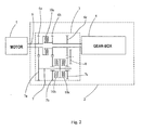
- 1 generally indicates a control system for a transmission 2 of an agricultural vehicle or an industrial off-highway vehicle (not shown) comprising a primary motor 5 and a clutch unit 3 interposed between the motor 5 and a gear-box 4.
- the primary motor 5 of the vehicle is of the endothermic or electrical type or of some other type.
- the clutch unit is placed downstream of the gear-box.
- the clutch unit may be positioned along the transmission, at any point between the motor and the driving wheels.
- the clutch unit 3 comprises a first shaft 6, for connection between the motor 5 and the gear-box 4, and a second shaft 7, namely a layshaft, parallel with the first shaft 6.
- a first gearwheel 6a Arranged in succession along the shaft 6, from the motor 5 to the gear-box 4, are a first gearwheel 6a, a first clutch 10a, which are dedicated to high speeds, a second gearwheel 6b and a third gearwheel 6c.
- a fourth gearwheel 7a meshing with the first gearwheel 6a
- a fifth wheel 7b meshing with the second gearwheel 6b
- a second clutch 10b which are dedicated to low speeds
- a third clutch 10c dedicated to reverse
- a sixth gearwheel 7c meshing on an intermediate wheel 8 which in turn meshes on the third gearwheel 6c.
- the three clutches 10a,b,c are of the multi-plate type, being provided with respective packs of plates 21 a,b,c interposed between respective pluralities of counter-plates 71 a,b,c and subjected to a flow of lubricating and cooling oil.
- the clutches 10a,b,c have the same structure and operation which are known per se and which are in any case based geometrically on the section shown in Figure 1 .
- the present control system is in any case adaptable also to other transmissions, for example having a number of clutches other than three, or having clutches of a different type, such as single-plate clutches.
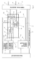
- FIGS. 2 and 3 show the control system 1 by means of two respective functional schematic diagrams in which the components of the control system 1 are represented by respective blocks and the quantities exchanged between the components, in the form of electrical signals, are represented by arrows, as described in detail hereinafter.
- the control system 1 comprises a plurality of sensors 11 suitable for measuring a plurality of characteristic quantities of the transmission, including the analogue quantities of the input and output speed of the clutch, the temperature and the pressure of the control and lubricating oil and the discrete quantities indicating the state of the transmission, such as the position of the vehicle direction lever. That plurality of quantities is converted into a plurality of raw digital signals 12 as input into the control system 1, which signals are generated inside the sensors themselves as regards the discrete quantities or in respective converters 13 as regards the analogue quantities.
- the sensors and converters are connected to an input signal processing module 15 which receives the digital signals 12 and processes them, eliminating the noise from the discrete signals and filtering the digital signals, converting them into operative input quantities 14 to be transmitted within the control system 1 by means of respective signals.
- the control system 1 comprises a controller 24 of the main hydraulic circuit, the main hydraulic circuit being that used to actuate the clutches 10a,b,c.
- the controller 24 of the main hydraulic circuit receives the operative input signals 14 from the input signal processor 15 and three signals indicating the state of the clutches 10a,b,c from the clutch controllers 25a,b,c, respectively.
- the controller 24 of the main hydraulic circuit processes the signals 14 and 43, identifying the condition of travel of the vehicle and of the clutch and generating enabling signals 26, which are transmitted to the three respective clutch controllers 25a,b,c in order to enable or disable the respective clutches 10a,b,c.
- the control system 1 comprises a power take-off controller 27 which receives the operative input signals 14 relating to a power take-off (not shown) of the agricultural vehicle, and processes them to generate a reference signal 31 which can be used to control the power take-off and which is transmitted to the three clutch controllers 25a,b,c, as well as to a device 50 for generating output power signals which receives the reference signal 31 and processes it to generate a power signal 52 by means of which the hydraulic control actuation of the power take-off of the vehicle is controlled, in accordance with known methodologies which are not subject-matter of the present invention.
- the control system 1 comprises a first torque reference generator 28 which receives the operative input signals 14 and processes them, identifying the position of a clutch pedal (not shown) and determining a first input torque 29 as a function of the position of the pedal. Therefore, the torque reference generated by the torque generator is represented by a reference signal managed by the control system 1 and corresponding to a predetermined torque value generated on the basis of predetermined parameters or conditions.
- the first torque reference generator 28 is also connected electrically - or, to be more precise, functionally - to the three respective clutch controllers 25a,b,c to supply a signal proportional to the first input torque 29.
- the control system 1 also comprises a second torque reference generator 20 formed by an automatic ramp generator connected to the input signal processor 15 from which it receives the operative input signals 14 and processes them to identify the condition of travel of the vehicle and the commands transmitted by the user and to generate, as a function thereof, a second input torque 22 generated on the basis of predefined time-torque maps.
- a second torque reference generator 20 formed by an automatic ramp generator connected to the input signal processor 15 from which it receives the operative input signals 14 and processes them to identify the condition of travel of the vehicle and the commands transmitted by the user and to generate, as a function thereof, a second input torque 22 generated on the basis of predefined time-torque maps.
- the second torque reference generator 20 is connected functionally to the three respective clutch controllers 25a,b,c to supply a signal proportional to the second input torque 22.
- the clutch controllers 25a,b,c have the same structure and operation and consequently only the clutch controller 25a for controlling the clutch 10a will be described in detail hereinafter.
- the clutch controller 25a receives the signals of the first input torque 29 and of the second input torque 22 and one of the enabling signals 26 and processes them to generate a voltage reference 42 for supplying a proportional valve (not shown) of the hydraulic actuating circuit of the clutch 10a.
- the clutch controller is connected to the device 50 for the generation of output power signals, which receives the voltage reference 42 and processes it to generate a power signal 51 by means of which a proportional valve of the hydraulic actuating circuit is actuated, which valve controls the movement of the plates and the pressure applied to the plates 21 a of the clutch 10a.
- the clutch controller 25a comprises:
- the torque processor 37 receives, in addition to the first input torque 29 and the second input torque 22, also a third input torque 39 calculated by the thermal load managing device 45, and calculates the reference torque 38 as the lowest value of the first, second and third input torques 29, 22, 39.
- the torque processor 37 receives only the first input torque 29 and the second input torque 22 and calculates the reference torque 38 as the lower value of the first and second input torques 29, 22.
- the controller 40 is connected to the operative input signals 14, in particular receiving through those signals the digital quantities which represent the input and output speeds of the clutch, the temperature and pressure of the actuating and lubricating oil and the current circulating in the solenoid of the proportional valve of the hydraulic actuating circuit of the clutch 10a.
- the controller 40 is formed by a pressure request generator 40a, a pressure control 40b and a current control 40c, which are arranged in series, respectively.
- the pressure request generator 40a receives the reference torque 38, the input and output speeds of the clutch and the temperature of the actuating and lubricating oil and processes them to generate a reference pressure, transmitted to the pressure control 40b which compares it with the measured pressure of the actuating oil to generate a current reference.
- the current control 40c receives the current reference and compares it with the current measured in the solenoid of the proportional valve of the hydraulic actuating circuit of the clutch 10a to generate the voltage reference 42.
- the controller 40 also generates a state signal 43, identifying the state of the clutch 10a, which is sent both to the controller 24 of the main hydraulic circuit in order to calculate the enabling signal 26, and to the thermal load managing device 45.
- the state signal 43 is generated as output from the pressure control 40b, also taking into account the signals generated by the pressure request generator 40a and by the current control 40c.
- the thermal load managing device 45 receives the same signals as the controller, that is to say, the operative input signals 14 and the reference torque 38, as well as the signals 31 and 43 identifying the state of the power take-off and the clutch and uses them to monitor the thermal state of the clutch.
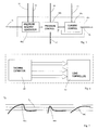
- the thermal load managing device 45 identifies an increase in the power dissipated in the plate packs 21 a,b,c in the slipping condition, with attainment of the threshold power, equal to the power carried off by the lubricating oil, and consequent raising of the temperature of the plates, the thermal load managing device 45 intervenes to modify the balance between power dissipated by the clutch and power carried off by the lubricant in the plates, operating principally in accordance with one or more of the following strategies:
- the purpose of the thermal load managing device 45 is to control the equilibrium between the power dissipated by the clutch in slipping conditions and the power carried off by the flow of lubricating oil which passes through the clutch pack, in such a manner as to regulate the temperature of the plates in accordance with one or more predefined threshold values To, T 1 of the friction material used to manufacture the clutch plates, above which values the efficiency characteristics of the clutch deteriorate to the extent that it may be damaged.
- the thermal load managing device 45 is operated when the temperature of the plates exceeds a predefined maximum value T 0 , for example 250°C.
- the thermal load managing device 45 is operated when the temperature of the plates exceeds a value T 1 within the predefined threshold range, for example 245°C or at any rate slightly lower than that of the first strategy 80a, with a growth gradient greater than a predefined threshold, for example 2°C/s.
- the use of two thresholds of temperature and gradient in the second strategy 80b makes it possible to identify cases such as that of the curve 80c in which it is not necessary for the thermal load managing device 45 to intervene when the temperature threshold is exceeded because the temperature of the plates is in any case close to reaching an equilibrium value which is not critical for performance or damage to the material of the clutch plates.
- the thermal load managing device 45 comprises a thermal estimator 60 which implements the known heat exchange equations in forced convection regime in order to calculate the temperature of the plates, the power dissipated in the plates and the power removed by the lubricating oil as a function of the thermal capacity and the thermal conductivity of the plates and the flow rate of the lubricating oil.
- the quantities calculated by the thermal estimator 60 are sent to a load controller 61 which processes them to generate an operative datum which can be used by the control system 1 to limit the thermal power dissipated in the clutch 10a or to increase the power removed by the lubricating oil.
- P lube represents the thermal power removed by the lubricating oil.
- the thermal load managing device 45 intervenes on the torque transmitted by the clutch, limiting it to a saturation torque ⁇ SAT , calculated in accordance with the relation D, derived from the relation C, substituting ⁇ sat for ⁇ clutch : ⁇ sat ⁇ P lube ⁇ slipping
- the thermal load managing device 45 intervenes on the slipping speed, limiting it to a saturation speed ⁇ sat , calculated according to relation E, derived from relation C, substituting ⁇ sat for ⁇ slipping : ⁇ sat ⁇ P lube ⁇ clutch
- the slipping speed can be controlled by acting on the input speed of the clutch, that speed being typically linked to the motor speed. This type of intervention is therefore possible only if the control system 1 can intervene on the motor and if the variations required of the motor are compatible with its torque curve.
- the thermal load managing device 45 can therefore intervene on the flow rate of the lubricating oil, determining the minimum flow rate of lubricant which must be sent to the clutch in order to prove the relation A.
- the thermal load managing device 45 generates a reference signal 46 corresponding to a datum of slipping speed and a datum of lubricating oil flow rate, respectively, which is transmitted to the device 50 for the generation of output power signals which receives the reference signal 46 and processes it to generate a power signal 53 by means of which the clutch input speed or the lubricating oil flow rate, respectively, is controlled.
- the thermal load managing device 45 when the lubricating oil flow rate reaches the maximum possible value, or when the hydraulic circuit of the lubricating oil is in a condition of failure, it is possible to provide for a switch-over to operation of the thermal load managing device 45 according to the first variant (control of the saturation torque) or according to the second variant (control of the clutch slipping speed).
- the control system 1 permits efficient control of the thermal power generated by the clutch plates through friction, enabling the object of the present invention to be achieved.
- the control method 100 comprises:
- the phase 170 consists in determining a third input torque 39 as a function of the thermal power carried off by the flow of the lubricating oil and the phase 180 consists in calculating the reference torque 38 as the lowest value of the first, second and third input torques 29, 22 and 39.
- the phase 170 consists in calculating an input speed of the clutch 10a as a function of a maximum value of the thermal power carried off by the flow of the lubricating oil and the phase 180 consists in calculating a reference speed signal 46 in order to supply a control signal 53 to the transmission to set the input speed of the clutch 10a.
- the phase 170 consists in calculating a flow rate of the oil in the hydraulic lubrication circuit of the clutch 10a as a function of a maximum value of the thermal power dissipated in the clutch 10a and the phase 180 consists in calculating a reference flow rate signal 46 in order to supply a control signal 53 to the hydraulic lubrication oil circuit to set the oil flow rate.
- the control method 100 can be carried out by means of a computer program comprising instructions which, when loaded into a computer memory, are suitable for performing all of the phases of the method 100.
- That program can likewise be represented by Figures 3 and 4 in which the blocks are modules of the program and the arrows represent the exchange of data between those program modules.
Landscapes
- Engineering & Computer Science (AREA)
- General Engineering & Computer Science (AREA)
- Physics & Mathematics (AREA)
- Fluid Mechanics (AREA)
- Mechanical Engineering (AREA)
- Hydraulic Clutches, Magnetic Clutches, Fluid Clutches, And Fluid Joints (AREA)
- Control Of Transmission Device (AREA)
Priority Applications (1)
| Application Number | Priority Date | Filing Date | Title |
|---|---|---|---|
| PL11773858T PL2616705T3 (pl) | 2010-09-13 | 2011-09-12 | System i sposób sterowania przeniesieniem napędu pojazdu |
Applications Claiming Priority (2)
| Application Number | Priority Date | Filing Date | Title |
|---|---|---|---|
| ITPD2010A000273A IT1401709B1 (it) | 2010-09-13 | 2010-09-13 | Sistema di controllo per una trasmissione di un veicolo agricolo o industriale e metodo di controllo per una trasmissione di un veicolo agricolo o industriale |
| PCT/IB2011/053980 WO2012035485A1 (en) | 2010-09-13 | 2011-09-12 | Control system and method for the transmission of a vehicle |
Publications (2)
| Publication Number | Publication Date |
|---|---|
| EP2616705A1 EP2616705A1 (en) | 2013-07-24 |
| EP2616705B1 true EP2616705B1 (en) | 2014-07-23 |
Family
ID=43500206
Family Applications (1)
| Application Number | Title | Priority Date | Filing Date |
|---|---|---|---|
| EP11773858.3A Active EP2616705B1 (en) | 2010-09-13 | 2011-09-12 | Control system and method for the transmission of a vehicle |
Country Status (7)
| Country | Link |
|---|---|
| US (1) | US8965646B2 (pl) |
| EP (1) | EP2616705B1 (pl) |
| BR (1) | BR112013005938B1 (pl) |
| ES (1) | ES2519367T3 (pl) |
| IT (1) | IT1401709B1 (pl) |
| PL (1) | PL2616705T3 (pl) |
| WO (1) | WO2012035485A1 (pl) |
Families Citing this family (4)
| Publication number | Priority date | Publication date | Assignee | Title |
|---|---|---|---|---|
| DE102013205107A1 (de) * | 2012-04-16 | 2013-10-17 | Schaeffler Technologies AG & Co. KG | Verfahren zum Kontrollieren einer nasslaufenden Reibungskupplung |
| CN104863988B (zh) * | 2015-04-10 | 2018-01-19 | 北汽福田汽车股份有限公司 | 车辆以及离合器操纵机构、控制系统和方法 |
| CN113665371B (zh) * | 2021-09-14 | 2023-06-13 | 上汽通用五菱汽车股份有限公司 | 电驱系统过温保护方法、车辆及可读存储介质 |
| WO2023161696A1 (en) * | 2022-02-23 | 2023-08-31 | Mahle Anand Thermal Systems Private Limited | System and method for controlling a clutch operation |
Family Cites Families (8)
| Publication number | Priority date | Publication date | Assignee | Title |
|---|---|---|---|---|
| US7077783B2 (en) * | 2000-09-15 | 2006-07-18 | Robert Bosch Gmbh | Method and device for operating a clutch |
| DE10330944A1 (de) | 2003-07-08 | 2005-02-03 | Oberschelp, Axel | Mischfaservlies oder-gewebe |
| ATE401512T1 (de) * | 2003-12-13 | 2008-08-15 | Gkn Driveline Int Gmbh | Verfahren zur temperaturabhängigen regelung einer lamellenkupplung |
| DE102004023581A1 (de) * | 2004-05-13 | 2005-12-08 | Adam Opel Ag | Verfahren zur Steuerung einer Kupplung und/oder eines Kraftfahrzeuggetriebes |
| FR2883609B1 (fr) * | 2005-03-25 | 2007-06-01 | Renault Sas | Procede de commande du glissement d'un systeme d'embrayage humide |
| DE102005026615A1 (de) * | 2005-06-09 | 2006-12-14 | Zf Friedrichshafen Ag | Verfahren und Vorrichtung zur Steuerung einer automatisierten Reibkupplung zwischen einem Motor und einem Getriebe |
| JP4945139B2 (ja) | 2006-01-27 | 2012-06-06 | 日立オートモティブシステムズ株式会社 | 自動車の制御装置 |
| DE102009037344A1 (de) | 2009-08-14 | 2011-02-17 | Volkswagen Ag | Verfahren zur Steuerung der Kühlmittelzufuhr und der Schmiermittelzufuhr einer Kupplung eines Kraftfahrzeuges mit einem automatischen Schaltgetriebe |
-
2010
- 2010-09-13 IT ITPD2010A000273A patent/IT1401709B1/it active
-
2011
- 2011-09-12 BR BR112013005938-9A patent/BR112013005938B1/pt active IP Right Grant
- 2011-09-12 US US13/823,074 patent/US8965646B2/en active Active
- 2011-09-12 EP EP11773858.3A patent/EP2616705B1/en active Active
- 2011-09-12 PL PL11773858T patent/PL2616705T3/pl unknown
- 2011-09-12 ES ES11773858.3T patent/ES2519367T3/es active Active
- 2011-09-12 WO PCT/IB2011/053980 patent/WO2012035485A1/en not_active Ceased
Also Published As
| Publication number | Publication date |
|---|---|
| PL2616705T3 (pl) | 2015-01-30 |
| US8965646B2 (en) | 2015-02-24 |
| IT1401709B1 (it) | 2013-08-02 |
| ES2519367T3 (es) | 2014-11-06 |
| WO2012035485A1 (en) | 2012-03-22 |
| US20130184950A1 (en) | 2013-07-18 |
| BR112013005938B1 (pt) | 2021-01-26 |
| EP2616705A1 (en) | 2013-07-24 |
| ITPD20100273A1 (it) | 2012-03-14 |
| BR112013005938A2 (pt) | 2016-05-24 |
Similar Documents
| Publication | Publication Date | Title |
|---|---|---|
| US9789876B1 (en) | Axle torque control system for a motor vehicle | |
| CN102481860B (zh) | 用于控制电驱动机械的驾驶方向的方法和系统 | |
| KR102446030B1 (ko) | 하이브리드 자동 변속기들에서 에너지율 밸런싱을 위한 시스템 및 방법 | |
| US9856932B2 (en) | System and method to predict the remaining useful life of a clutch by coefficient of friction estimation | |
| EP2616705B1 (en) | Control system and method for the transmission of a vehicle | |
| CA2822573A1 (en) | Clutch temperature estimation for a mobile machine | |
| US20170225676A1 (en) | Control device for vehicle drive device | |
| US9709164B2 (en) | Transmission component failure detection and avoidance | |
| CN101636605A (zh) | 带变矩器的车辆用自动变速器的变矩器的油温过度上升防止装置 | |
| US8500599B2 (en) | Machine powertrain and method | |
| EP2984370B1 (en) | Direct drive hydrostatic transmission | |
| EP3008362B1 (en) | Vehicle transmission and a method for operating a vehicle transmission | |
| WO2017099655A1 (en) | A method and a system for controlling an output torque of an electric machine in a vehicle | |
| US8801571B2 (en) | Machine powertrain and method | |
| EP2644948B1 (en) | System and method for controlling the pressure of hydraulic fluid supplied within a work vehicle transmission | |
| CN111486228B (zh) | 用于运行车辆的传动系的方法 | |
| KR102699863B1 (ko) | 하이브리드 클러치의 슬립 출력을 계산하기 위한 방법 | |
| CN104514871A (zh) | 二元离合器组件的基于能量的换挡控制 | |
| JP6541780B2 (ja) | 車両のパワートレインを制御するための方法 | |
| Rajagopal et al. | Electro-Hydraulic Shuttle Transmission and Control for Tractors with Non-Electronic Engine | |
| US11400937B2 (en) | Method for controlling a driveline of a vehicle | |
| JP2018194133A (ja) | 自動変速機の制御装置 | |
| JP2018194131A (ja) | 自動変速機の制御装置 | |
| KR20140106028A (ko) | 동력원의 토크 제어를 위한 테이블 데이터가 기록된 기록매체 | |
| CN103827534A (zh) | 用于控制机动车辆推进装置的装置和方法 |
Legal Events
| Date | Code | Title | Description |
|---|---|---|---|
| PUAI | Public reference made under article 153(3) epc to a published international application that has entered the european phase |
Free format text: ORIGINAL CODE: 0009012 |
|
| 17P | Request for examination filed |
Effective date: 20130322 |
|
| AK | Designated contracting states |
Kind code of ref document: A1 Designated state(s): AL AT BE BG CH CY CZ DE DK EE ES FI FR GB GR HR HU IE IS IT LI LT LU LV MC MK MT NL NO PL PT RO RS SE SI SK SM TR |
|
| DAX | Request for extension of the european patent (deleted) | ||
| GRAP | Despatch of communication of intention to grant a patent |
Free format text: ORIGINAL CODE: EPIDOSNIGR1 |
|
| INTG | Intention to grant announced |
Effective date: 20140305 |
|
| GRAS | Grant fee paid |
Free format text: ORIGINAL CODE: EPIDOSNIGR3 |
|
| GRAA | (expected) grant |
Free format text: ORIGINAL CODE: 0009210 |
|
| AK | Designated contracting states |
Kind code of ref document: B1 Designated state(s): AL AT BE BG CH CY CZ DE DK EE ES FI FR GB GR HR HU IE IS IT LI LT LU LV MC MK MT NL NO PL PT RO RS SE SI SK SM TR |
|
| REG | Reference to a national code |
Ref country code: GB Ref legal event code: FG4D |
|
| REG | Reference to a national code |
Ref country code: CH Ref legal event code: EP |
|
| REG | Reference to a national code |
Ref country code: IE Ref legal event code: FG4D |
|
| REG | Reference to a national code |
Ref country code: AT Ref legal event code: REF Ref document number: 679053 Country of ref document: AT Kind code of ref document: T Effective date: 20140815 |
|
| REG | Reference to a national code |
Ref country code: DE Ref legal event code: R096 Ref document number: 602011008634 Country of ref document: DE Effective date: 20140904 |
|
| REG | Reference to a national code |
Ref country code: CH Ref legal event code: NV Representative=s name: WEINMANN ZIMMERLI, CH |
|
| REG | Reference to a national code |
Ref country code: ES Ref legal event code: FG2A Ref document number: 2519367 Country of ref document: ES Kind code of ref document: T3 Effective date: 20141106 |
|
| REG | Reference to a national code |
Ref country code: SE Ref legal event code: TRGR |
|
| REG | Reference to a national code |
Ref country code: NL Ref legal event code: T3 |
|
| REG | Reference to a national code |
Ref country code: LT Ref legal event code: MG4D |
|
| PG25 | Lapsed in a contracting state [announced via postgrant information from national office to epo] |
Ref country code: BG Free format text: LAPSE BECAUSE OF FAILURE TO SUBMIT A TRANSLATION OF THE DESCRIPTION OR TO PAY THE FEE WITHIN THE PRESCRIBED TIME-LIMIT Effective date: 20141023 Ref country code: FI Free format text: LAPSE BECAUSE OF FAILURE TO SUBMIT A TRANSLATION OF THE DESCRIPTION OR TO PAY THE FEE WITHIN THE PRESCRIBED TIME-LIMIT Effective date: 20140723 Ref country code: NO Free format text: LAPSE BECAUSE OF FAILURE TO SUBMIT A TRANSLATION OF THE DESCRIPTION OR TO PAY THE FEE WITHIN THE PRESCRIBED TIME-LIMIT Effective date: 20141023 Ref country code: LT Free format text: LAPSE BECAUSE OF FAILURE TO SUBMIT A TRANSLATION OF THE DESCRIPTION OR TO PAY THE FEE WITHIN THE PRESCRIBED TIME-LIMIT Effective date: 20140723 Ref country code: PT Free format text: LAPSE BECAUSE OF FAILURE TO SUBMIT A TRANSLATION OF THE DESCRIPTION OR TO PAY THE FEE WITHIN THE PRESCRIBED TIME-LIMIT Effective date: 20141124 Ref country code: GR Free format text: LAPSE BECAUSE OF FAILURE TO SUBMIT A TRANSLATION OF THE DESCRIPTION OR TO PAY THE FEE WITHIN THE PRESCRIBED TIME-LIMIT Effective date: 20141024 |
|
| REG | Reference to a national code |
Ref country code: PL Ref legal event code: T3 |
|
| PG25 | Lapsed in a contracting state [announced via postgrant information from national office to epo] |
Ref country code: RS Free format text: LAPSE BECAUSE OF FAILURE TO SUBMIT A TRANSLATION OF THE DESCRIPTION OR TO PAY THE FEE WITHIN THE PRESCRIBED TIME-LIMIT Effective date: 20140723 Ref country code: HR Free format text: LAPSE BECAUSE OF FAILURE TO SUBMIT A TRANSLATION OF THE DESCRIPTION OR TO PAY THE FEE WITHIN THE PRESCRIBED TIME-LIMIT Effective date: 20140723 Ref country code: LV Free format text: LAPSE BECAUSE OF FAILURE TO SUBMIT A TRANSLATION OF THE DESCRIPTION OR TO PAY THE FEE WITHIN THE PRESCRIBED TIME-LIMIT Effective date: 20140723 Ref country code: IS Free format text: LAPSE BECAUSE OF FAILURE TO SUBMIT A TRANSLATION OF THE DESCRIPTION OR TO PAY THE FEE WITHIN THE PRESCRIBED TIME-LIMIT Effective date: 20141123 Ref country code: CY Free format text: LAPSE BECAUSE OF FAILURE TO SUBMIT A TRANSLATION OF THE DESCRIPTION OR TO PAY THE FEE WITHIN THE PRESCRIBED TIME-LIMIT Effective date: 20140723 |
|
| REG | Reference to a national code |
Ref country code: DE Ref legal event code: R097 Ref document number: 602011008634 Country of ref document: DE |
|
| PG25 | Lapsed in a contracting state [announced via postgrant information from national office to epo] |
Ref country code: SK Free format text: LAPSE BECAUSE OF FAILURE TO SUBMIT A TRANSLATION OF THE DESCRIPTION OR TO PAY THE FEE WITHIN THE PRESCRIBED TIME-LIMIT Effective date: 20140723 Ref country code: DK Free format text: LAPSE BECAUSE OF FAILURE TO SUBMIT A TRANSLATION OF THE DESCRIPTION OR TO PAY THE FEE WITHIN THE PRESCRIBED TIME-LIMIT Effective date: 20140723 Ref country code: EE Free format text: LAPSE BECAUSE OF FAILURE TO SUBMIT A TRANSLATION OF THE DESCRIPTION OR TO PAY THE FEE WITHIN THE PRESCRIBED TIME-LIMIT Effective date: 20140723 Ref country code: LU Free format text: LAPSE BECAUSE OF FAILURE TO SUBMIT A TRANSLATION OF THE DESCRIPTION OR TO PAY THE FEE WITHIN THE PRESCRIBED TIME-LIMIT Effective date: 20140912 Ref country code: MC Free format text: LAPSE BECAUSE OF FAILURE TO SUBMIT A TRANSLATION OF THE DESCRIPTION OR TO PAY THE FEE WITHIN THE PRESCRIBED TIME-LIMIT Effective date: 20140723 Ref country code: RO Free format text: LAPSE BECAUSE OF FAILURE TO SUBMIT A TRANSLATION OF THE DESCRIPTION OR TO PAY THE FEE WITHIN THE PRESCRIBED TIME-LIMIT Effective date: 20140723 |
|
| PLBE | No opposition filed within time limit |
Free format text: ORIGINAL CODE: 0009261 |
|
| STAA | Information on the status of an ep patent application or granted ep patent |
Free format text: STATUS: NO OPPOSITION FILED WITHIN TIME LIMIT |
|
| REG | Reference to a national code |
Ref country code: IE Ref legal event code: MM4A |
|
| REG | Reference to a national code |
Ref country code: HU Ref legal event code: AG4A Ref document number: E023141 Country of ref document: HU |
|
| PG25 | Lapsed in a contracting state [announced via postgrant information from national office to epo] |
Ref country code: BE Free format text: LAPSE BECAUSE OF NON-PAYMENT OF DUE FEES Effective date: 20140930 |
|
| 26N | No opposition filed |
Effective date: 20150424 |
|
| PG25 | Lapsed in a contracting state [announced via postgrant information from national office to epo] |
Ref country code: IE Free format text: LAPSE BECAUSE OF NON-PAYMENT OF DUE FEES Effective date: 20140912 |
|
| PG25 | Lapsed in a contracting state [announced via postgrant information from national office to epo] |
Ref country code: SI Free format text: LAPSE BECAUSE OF FAILURE TO SUBMIT A TRANSLATION OF THE DESCRIPTION OR TO PAY THE FEE WITHIN THE PRESCRIBED TIME-LIMIT Effective date: 20140723 |
|
| PG25 | Lapsed in a contracting state [announced via postgrant information from national office to epo] |
Ref country code: SM Free format text: LAPSE BECAUSE OF FAILURE TO SUBMIT A TRANSLATION OF THE DESCRIPTION OR TO PAY THE FEE WITHIN THE PRESCRIBED TIME-LIMIT Effective date: 20140723 |
|
| PG25 | Lapsed in a contracting state [announced via postgrant information from national office to epo] |
Ref country code: MT Free format text: LAPSE BECAUSE OF FAILURE TO SUBMIT A TRANSLATION OF THE DESCRIPTION OR TO PAY THE FEE WITHIN THE PRESCRIBED TIME-LIMIT Effective date: 20140723 |
|
| PG25 | Lapsed in a contracting state [announced via postgrant information from national office to epo] |
Ref country code: BE Free format text: LAPSE BECAUSE OF FAILURE TO SUBMIT A TRANSLATION OF THE DESCRIPTION OR TO PAY THE FEE WITHIN THE PRESCRIBED TIME-LIMIT Effective date: 20140723 |
|
| REG | Reference to a national code |
Ref country code: FR Ref legal event code: PLFP Year of fee payment: 6 |
|
| REG | Reference to a national code |
Ref country code: FR Ref legal event code: PLFP Year of fee payment: 7 |
|
| PG25 | Lapsed in a contracting state [announced via postgrant information from national office to epo] |
Ref country code: MK Free format text: LAPSE BECAUSE OF FAILURE TO SUBMIT A TRANSLATION OF THE DESCRIPTION OR TO PAY THE FEE WITHIN THE PRESCRIBED TIME-LIMIT Effective date: 20140723 |
|
| REG | Reference to a national code |
Ref country code: FR Ref legal event code: PLFP Year of fee payment: 8 |
|
| PG25 | Lapsed in a contracting state [announced via postgrant information from national office to epo] |
Ref country code: AL Free format text: LAPSE BECAUSE OF FAILURE TO SUBMIT A TRANSLATION OF THE DESCRIPTION OR TO PAY THE FEE WITHIN THE PRESCRIBED TIME-LIMIT Effective date: 20140723 |
|
| REG | Reference to a national code |
Ref country code: DE Ref legal event code: R082 Ref document number: 602011008634 Country of ref document: DE Ref country code: DE Ref legal event code: R081 Ref document number: 602011008634 Country of ref document: DE Owner name: CARRARO S.P.A., CAMPODARSEGO, IT Free format text: FORMER OWNER: CARRARO DRIVE TECH S.P.A., PADOVA, IT |
|
| REG | Reference to a national code |
Ref country code: CH Ref legal event code: NV Representative=s name: BOVARD SA NEUCHATEL CONSEILS EN PROPRIETE INTE, CH Ref country code: ES Ref legal event code: PC2A Owner name: CARRARO S.P.A. Effective date: 20200609 Ref country code: CH Ref legal event code: PUE Owner name: CARRARO S.P.A., IT Free format text: FORMER OWNER: CARRARO DRIVE TECH S.P.A., IT |
|
| REG | Reference to a national code |
Ref country code: GB Ref legal event code: 732E Free format text: REGISTERED BETWEEN 20200625 AND 20200701 |
|
| REG | Reference to a national code |
Ref country code: HU Ref legal event code: FH1C Free format text: FORMER REPRESENTATIVE(S): FOELDI JULIANNA, DANUBIA SZABADALMI ES JOGI IRODA KFT., HU Representative=s name: SBGK SZABADALMI UEGYVIVOEI IRODA, HU Ref country code: HU Ref legal event code: GB9C Owner name: CARRARO S.P.A., IT Free format text: FORMER OWNER(S): CARRARO DRIVE TECH S.P.A., IT |
|
| REG | Reference to a national code |
Ref country code: NL Ref legal event code: PD Owner name: CARRARO S.P.A.; IT Free format text: DETAILS ASSIGNMENT: CHANGE OF OWNER(S), ASSIGNMENT; FORMER OWNER NAME: CARRARO DRIVE TECH S.P.A. Effective date: 20200630 |
|
| REG | Reference to a national code |
Ref country code: AT Ref legal event code: PC Ref document number: 679053 Country of ref document: AT Kind code of ref document: T Owner name: CARRARO S.P.A., IT Effective date: 20200916 |
|
| P01 | Opt-out of the competence of the unified patent court (upc) registered |
Effective date: 20230710 |
|
| REG | Reference to a national code |
Ref country code: CH Ref legal event code: U11 Free format text: ST27 STATUS EVENT CODE: U-0-0-U10-U11 (AS PROVIDED BY THE NATIONAL OFFICE) Effective date: 20251001 |
|
| PGFP | Annual fee paid to national office [announced via postgrant information from national office to epo] |
Ref country code: DE Payment date: 20250919 Year of fee payment: 15 |
|
| PGFP | Annual fee paid to national office [announced via postgrant information from national office to epo] |
Ref country code: PL Payment date: 20250908 Year of fee payment: 15 Ref country code: TR Payment date: 20250908 Year of fee payment: 15 Ref country code: IT Payment date: 20250819 Year of fee payment: 15 Ref country code: NL Payment date: 20250918 Year of fee payment: 15 |
|
| PGFP | Annual fee paid to national office [announced via postgrant information from national office to epo] |
Ref country code: HU Payment date: 20250922 Year of fee payment: 15 Ref country code: GB Payment date: 20250918 Year of fee payment: 15 |
|
| PGFP | Annual fee paid to national office [announced via postgrant information from national office to epo] |
Ref country code: FR Payment date: 20250922 Year of fee payment: 15 Ref country code: AT Payment date: 20250919 Year of fee payment: 15 |
|
| PGFP | Annual fee paid to national office [announced via postgrant information from national office to epo] |
Ref country code: SE Payment date: 20250918 Year of fee payment: 15 |
|
| PGFP | Annual fee paid to national office [announced via postgrant information from national office to epo] |
Ref country code: CZ Payment date: 20250904 Year of fee payment: 15 |
|
| PGFP | Annual fee paid to national office [announced via postgrant information from national office to epo] |
Ref country code: CH Payment date: 20251001 Year of fee payment: 15 |
|
| PGFP | Annual fee paid to national office [announced via postgrant information from national office to epo] |
Ref country code: ES Payment date: 20251028 Year of fee payment: 15 |
|
| REG | Reference to a national code |
Ref country code: CH Ref legal event code: R18 Free format text: ST27 STATUS EVENT CODE: U-0-0-R10-R18 (AS PROVIDED BY THE NATIONAL OFFICE) Effective date: 20260209 |
|
| REG | Reference to a national code |
Ref country code: CH Ref legal event code: R18 Free format text: ST27 STATUS EVENT CODE: U-0-0-R10-R18 (AS PROVIDED BY THE NATIONAL OFFICE) Effective date: 20260320 |