EP2615999B1 - Ajustement de prothèses dentaires basé sur le tissu mou - Google Patents
Ajustement de prothèses dentaires basé sur le tissu mou Download PDFInfo
- Publication number
- EP2615999B1 EP2615999B1 EP11824659.4A EP11824659A EP2615999B1 EP 2615999 B1 EP2615999 B1 EP 2615999B1 EP 11824659 A EP11824659 A EP 11824659A EP 2615999 B1 EP2615999 B1 EP 2615999B1
- Authority
- EP
- European Patent Office
- Prior art keywords
- emergence
- soft tissue
- dental prosthesis
- model
- scan
- Prior art date
- Legal status (The legal status is an assumption and is not a legal conclusion. Google has not performed a legal analysis and makes no representation as to the accuracy of the status listed.)
- Active
Links
- 210000004872 soft tissue Anatomy 0.000 title claims description 131
- 238000000034 method Methods 0.000 claims description 47
- 239000007943 implant Substances 0.000 claims description 36
- 230000005415 magnetization Effects 0.000 claims description 10
- 238000003860 storage Methods 0.000 claims description 10
- 238000004519 manufacturing process Methods 0.000 claims description 5
- 230000008859 change Effects 0.000 claims description 4
- 230000008569 process Effects 0.000 description 11
- 238000004891 communication Methods 0.000 description 9
- 238000013461 design Methods 0.000 description 8
- 230000008901 benefit Effects 0.000 description 6
- 230000015654 memory Effects 0.000 description 5
- 241000699666 Mus <mouse, genus> Species 0.000 description 4
- 238000009877 rendering Methods 0.000 description 4
- 238000004040 coloring Methods 0.000 description 3
- 230000007246 mechanism Effects 0.000 description 3
- 238000012545 processing Methods 0.000 description 3
- 230000006835 compression Effects 0.000 description 2
- 238000007906 compression Methods 0.000 description 2
- 230000000694 effects Effects 0.000 description 2
- 238000005516 engineering process Methods 0.000 description 2
- 230000035876 healing Effects 0.000 description 2
- 238000012986 modification Methods 0.000 description 2
- 230000004048 modification Effects 0.000 description 2
- 238000003825 pressing Methods 0.000 description 2
- 230000003068 static effect Effects 0.000 description 2
- 241000699670 Mus sp. Species 0.000 description 1
- 239000003086 colorant Substances 0.000 description 1
- 238000002591 computed tomography Methods 0.000 description 1
- 230000008878 coupling Effects 0.000 description 1
- 238000010168 coupling process Methods 0.000 description 1
- 238000005859 coupling reaction Methods 0.000 description 1
- 238000010586 diagram Methods 0.000 description 1
- 238000005538 encapsulation Methods 0.000 description 1
- 230000006870 function Effects 0.000 description 1
- 210000004195 gingiva Anatomy 0.000 description 1
- 238000003780 insertion Methods 0.000 description 1
- 230000037431 insertion Effects 0.000 description 1
- 230000003287 optical effect Effects 0.000 description 1
Images


Classifications
-
- A—HUMAN NECESSITIES
- A61—MEDICAL OR VETERINARY SCIENCE; HYGIENE
- A61C—DENTISTRY; APPARATUS OR METHODS FOR ORAL OR DENTAL HYGIENE
- A61C13/00—Dental prostheses; Making same
- A61C13/0003—Making bridge-work, inlays, implants or the like
- A61C13/0004—Computer-assisted sizing or machining of dental prostheses
-
- A—HUMAN NECESSITIES
- A61—MEDICAL OR VETERINARY SCIENCE; HYGIENE
- A61C—DENTISTRY; APPARATUS OR METHODS FOR ORAL OR DENTAL HYGIENE
- A61C8/00—Means to be fixed to the jaw-bone for consolidating natural teeth or for fixing dental prostheses thereon; Dental implants; Implanting tools
- A61C8/0048—Connecting the upper structure to the implant, e.g. bridging bars
- A61C8/0077—Connecting the upper structure to the implant, e.g. bridging bars with shape following the gingival surface or the bone surface
-
- A—HUMAN NECESSITIES
- A61—MEDICAL OR VETERINARY SCIENCE; HYGIENE
- A61C—DENTISTRY; APPARATUS OR METHODS FOR ORAL OR DENTAL HYGIENE
- A61C8/00—Means to be fixed to the jaw-bone for consolidating natural teeth or for fixing dental prostheses thereon; Dental implants; Implanting tools
- A61C8/0048—Connecting the upper structure to the implant, e.g. bridging bars
- A61C8/005—Connecting devices for joining an upper structure with an implant member, e.g. spacers
Definitions
- the present application generally relates to dental planning, and more particularly to adjusting dental prostheses based on soft tissue.
- the use of computer systems to design dental prostheses has increased in recent years.
- the computer systems allow a dentist, dental technician, or other operator to design dental prostheses for individual patients. These individual prosthesis designs are often called “situations,” “dental plans,” or “prosthetic plans.” Operators using the computer systems can design plans based on a library of the teeth shapes and positions, patient data, and available equipment and hardware.
- abutment shapes were manipulated by hand.
- an operator might be given access to a 3D scan of the soft tissue in the area where an abutment would be placed.
- the operator could manipulate individual "handles" on the 3D model in order to move the 3D surface of the abutment relative to the soft tissue (e.g., to match the soft tissue's 3D surface).
- manipulating the 3D surface of the abutment can be time consuming and difficult.
- the operator would have to manipulate multiple individual points on the 3D surface of the abutment in order to attempt to form it to the desired shape.
- the present invention relates to a computer-implemented method according to claim 1, a system for adjusting dental prostheses according to claim 11, and a computer-readable storage medium according to claim 16.
- Embodiments herein include techniques, methods, systems, devices, and computer-readable media for adjusting dental prostheses based on soft tissue, including receiving a 3D scan of soft tissue of the patient.
- the 3D scan of the soft tissue of the patient can include an emergence portion.
- the emergence portion of the 3D scan of the soft tissue may extend from an area associated with an implant attached to said patient, to an area where a dental prosthesis attached to said implant would emerge from said soft tissue.
- Emergence limit information for an emergence surface of a 3D model of the dental prosthesis may be received. Desired offset information for the emergence surface of the 3D model of the dental prosthesis may be received.
- the offset information comprises a distance between the emergence surface of the 3D model of the dental prosthesis and the emergence portion of the 3D scan of the soft tissue.
- a shape of the emergence surface of the 3D model of the dental prosthesis may be determined based on the emergence portion of the 3D scan of the soft tissue, the emergence limit information, and the offset information. Further, manufacturing data related to the dental prosthesis may be produced.
- an operator such as a dentist, dental surgeon, or the like, can define the portion (“the emergence portion") of a prosthesis', such as an abutment's, surface that runs from the implant, through the soft tissue ("the emergence surface"), to the base of the prosthesis.
- the emergence portion of the prosthesis' surface may be roughly matched to the soft tissue's surface by defining a desired offset from the soft tissue and effectuating the offset by, for example, pressing a button or performing a keystroke.
- the operator may first perform a 3D scan of the soft tissue around the area in which the abutment will be placed. In some cases, the 3D scan of the soft tissue may come from another lab or another operator.
- the operator can use the 3D scan of the soft tissue as a guide for creating the abutment.
- the operator can define an offset to make the abutment's 3D emergence surface larger than, smaller than, or equal to (zero offset) the 3D scan of the soft tissue.
- the 3D emergence surface of the abutment is modified automatically to be offset from the 3D scan of the soft tissue by the desired amount.
- Embodiments herein may be used to design any type of prosthesis that may emerge through soft tissue.
- An operator might want to design a dental prosthesis so that, once it is installed in the patient's mouth, it will compress the surrounding soft tissue, thereby leaving no gap between the dental prosthesis and the soft tissue.
- the operator may want to match the dental prosthesis with the soft tissue, thereby reducing both the gap between the soft tissue in the dental prosthesis as well as the compression of the soft tissue.
- the operator may want to leave a gap between the dental prosthesis and the soft tissue.
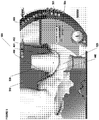
- FIG. 1 depicts an interface 100 that has a global abstraction portion 111, an overlaid representation portion 110, and depicts the 3D scan of soft tissue 120, as well as an abutment 130.
- the operator can use the global abstraction portion 111 to selectively turn on and off the viewing of certain items that will be displayed in overlaid representation portion 110.
- the operator may be able to turn on or off the viewing of a prosthesis such as abutment 130, the soft tissue 120, and/or any other item that may be displayed in the overlaid representation portion 110.
- Examples and embodiments of selection techniques are given in U.S. Pat. Appl. No. 12/703,601, filed February 10, 2010 , entitled Dental Prosthetics Manipulation, Selection, and Planning.
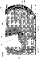
- FIG. 4 depicts an interface 400 including an overlaid representation portion 410.
- An operator can define an emergence limit 440 for a dental prosthesis (not pictured) with respect to the 3D scan of soft tissue 420.
- the 3D scan of the soft tissue has an "emergence portion.”
- the phrase "emergence portion of the 3D scan of the soft tissue" has its ordinary and customary meaning, which includes signifying at least a surface or a portion of a surface that extends from an emergence limit down toward a scanned implant. For example, an emergence portion of 3D scan 420 extends from an emergence limit 440 down to the implant, which is signaled as 445 in FIG. 4 .
- FIG. 5 depicts an interface 500 with an overlaid representation portion 510 and a control menu 560.
- the operator can define an emergence offset using an offset indicator 564 on control menu 560. After the emergence offset 564 is defined, the operator can press button 561 to adjust the dental prosthesis to the soft tissue, offset by the emergence offset.
- This dental prosthesis is depicted as 530 in FIG. 5 .
- Adjustments made to the surface of the 3D model of the prosthesis based on the emergence offset can be in any direction. For example, in some embodiments, the adjustments are made in a radial direction extending from the axis of the prosthesis outward.
- the emergence offset can define how the "emergence surface" of the 3D model of the dental prosthesis is positioned with respect to the emergence portion of the 3D scan of the soft tissue.
- the emergence surface may be the portion of the dental prosthesis' surface that extends from the implant, through the soft tissue, and ends where the dental prosthesis emerges from the soft tissue - at the emergence limit (e.g., emergence limit 440 of FIGS. 4 and 5 ).
- the phrase "emergence surface of the 3D model of the dental prosthesis" has its ordinary and customary meaning, which includes a surface on the 3D model of the dental prosthesis that roughly corresponds to the emergence portion of the 3D scan of the soft tissue.
- the emergence surface of the 3D model of the dental prosthesis may extend from the interface of the 3D model of the prosthesis with the underlying implant, up to an emergence limit.
- FIG. 10 depicts an emergence surface 1080 of 3D model of the dental prosthesis 1030 being depicted on the overlaid representation portion 1010 of interface 1000.
- the operator can define positive or negative emergence offsets.
- a positive offset indicates that the 3D model of the dental prosthesis will not extend as far, in a radial direction, for example, as the 3D scan of the gum.
- the emergence surface of the 3D model of the dental prosthesis will not cross over or extend beyond the emergence portion of the 3D scan of the soft tissue.
- the offset is negative, then the emergence surface of the 3D model of the dental prosthesis may extend beyond, in the radial direction, for example, and be wider or have a greater circumference than the emergence portion of the 3D scan of the soft tissue of the patient.
- the operator can very quickly and easily define an emergence surface of a 3D model of a prosthesis, such as an abutment, with the desired gap or compression of soft tissue.
- the effect of the signs of the offsets may be swapped, with negative offsets being associated with a gap and positive offsets being associated with the emergence surface of the dental prosthesis being wider than the scan of the soft tissue.
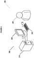
- FIG. 2 illustrates an example system 200 for adjusting prostheses based on soft tissue.
- the system 200 may include one or more computers 210 coupled to one or more displays 220, and one or more input devices 230.
- An operator 240 who may be a dentist, dental technician, or other person, may plan dental prostheses using system 200 by manipulating the one or more input devices 230, such as a keyboard and / or a mouse.
- the operator 240 may view the dental plan and other related dental plan data on the display 220.
- the display 220 may include two or more display regions or portions, each of which displays a different view of the dental plan.
- the display 220 may show a semi-realistic 3D rendering of the dental plan, a localized abstraction of the dental plan, and / or a cross-sectional representation of the dental plan.
- Each of these displays or portions may be linked internally within a program and / or using data on computer 210.
- a program running on a computer 210 may have a single internal representation of the dental plan in memory and the internal representation may be displayed in two or more abstract or semi-realistic manners on display 220.
- the operator 240 may be able to perform a command, such as select, move, manipulate, or make transparent, opaque, or invisible, on a particular substructure in the dental plan.
- the operator 240 may be able to perform this command by manipulating the input device 230, such as clicking with a mouse on a particular region of one of the abstract or semi-realistic versions of the dental plan displayed on the display 220.
- the computer 210 may include one or more processors, one or more memories, and one or more communication mechanisms. In some embodiments, more than one computer may be used to execute the modules, methods, blocks, and processes discussed herein. Additionally, the modules and processes herein may each run on one or multiple processors, on one or more computers; or the modules herein may run on dedicated hardware.
- the input devices 230 may include one or more keyboards (one-handed or two-handed), mice, touch screens, voice commands and associated hardware, gesture recognition, or any other means of providing communication between the operator 240 and the computer 210.
- the display 220 may be a two-dimensional ("2D") or 3D display and may be based on any technology, such as LCD, CRT, plasma, projection, etc.
- the communication among the various components of system 200 may be accomplished via any appropriate coupling, including USB, VGA cables, coaxial cables, FireWire, serial cables, parallel cables, SCSI cables, IDE cables, SATA cables, wireless based on 802.11 or Bluetooth, or any other wired or wireless connection(s).
- One or more of the components in system 200 may also be combined into a single unit or module. In some embodiments, all of the electronic components of system 200 are included in a single physical unit or module.
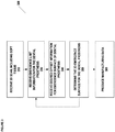
- FIG. 3 depicts a method 300 for adjusting a dental prosthesis based on soft tissue.
- a 3D scan of soft tissue is received.
- this 3D scan may contain an emergence portion that defines the area in which a dental prosthesis, such as an abutment, will be proximal to the soft tissue.
- a dental surgeon implanted an implant into a patient and then placed a healing abutment into the implant, soft tissue would form through an emergence portion down to the implant. Thereafter, the healing abutment would be taken out and a scan of the soft tissue would take place. That scan would be received in block 310.
- An example of that scan is depicted as 3D model 120 in FIG. 1 .
- the scan may be taken using any appropriate method including an intraoral scan, CT scan, MRI's, and the like.
- the scan could also be, in some embodiments, a surface scan of a physical model, where, for example, there is an implant replica representing the position of the implant relative to the soft tissue.
- the scan may be of the physical model, but it nevertheless can represent the 3D surface of the soft tissue.
- Various embodiments of scanning 3D models are given in U.S. Pat. Appl. No. 12/703,596 , entitled "Dental Data Planning," filed Feb. 10, 2010.
- placement information for a dental prosthesis may also be received. For example, some embodiments detect the position of the implant (e.g., by using an implant locator in a scan of a model). The position of the prosthesis or other abutment can be determined from the position of the implant. In some embodiments, a position locator could be attached to a model, and the model with the position locator attached could be scanned. The position of the implant can be defined from the position of the position locator in the scan. When a 3D model of a prosthesis is "attached" to the implant in the design software, the position of the prosthesis is thereby defined.
- the placement information may be, looking to the Example in FIG. 1 , that an abutment 130 will be placed on top of an implant through the 3D scan of the soft tissue 120, thereby obtaining the position of the abutment 120 in part, and indirectly, from the position of the implant.
- emergence limit information for a dental prosthesis is received.
- the emergence limit information may be a margin line or other line or curve defining the upper limit of the emergence surface of the 3D model of the dental prosthesis.
- defining the emergence limit 440 may be defined by manipulating manipulators 450, 451, 452.
- the emergence limit 440 and the base of the 3D model of the prosthesis e.g., a fixed diameter interface with the implant to which the 3D model of the prosthesis is attached
- the manipulators 450-452 are used to define the emergence limit 440.
- the manipulators 450-452 for an emergence limit 440 may be sorted radially (e.g., about the center axis of the associated implant) - and the emergence limit 440 may be determined based on the sorted manipulators 450-452.
- the emergence limit 440 may be defined as a curved line that passes through the manipulators 450-452.
- the emergence limit 440 may be formed using any appropriate algorithm or interpolation among these manipulators 450-452, including a second-degree NURBS curve, a spline, other NURBS, etc.
- the operator can add manipulation points to an emergence limit 440 by clicking on the line 440, clicking on the 3D surface 420, and the like.
- manipulators may allow the operator to refine the emergence limit 440.
- the operator can also remove manipulation points 450-452 from the emergence limit 440 by dragging manipulators 450-452 off the screen, right-clicking on manipulators 450-452, performing particular keystrokes, and the like.
- FIG. 11 illustrates an interface 1100 with an overlapped representation portion 1110 depicting two emergence limits 1140 and 1141 on the 3D scan of soft tissue 1130.
- the techniques herein may sort any received or defined manipulators 1150, 1151, 1152, 1153 by their proximity to implants and thereby define which of the manipulators 1150, 1151, 1152, 1153 are associated with each emergence limit 1140, 1141 (e.g., by associating manipulators 1150-1153 with the implant to which it is closest). From there, the manipulators 1150, 1151 that are associated together are used to define the emergence limit 1140, as described above. As described above, manipulators may be added to an emergence limit.
- emergence limit 1141 For example, looking at emergence limit 1141, we see that it crosses over an "open space" as it interpolates between two of the manipulators 1152 and 1153. An operator may want to add another manipulator in order to match the emergence limit 1141 to the surface 1130 and/or to alter the emergence limit's 1141 shape.
- the emergence limit information for the dental prosthesis is received in block 330
- desired offset information for the emergence surface of the 3D model of the dental prosthesis is received in block 340.
- the emergence limit information may be received from an operator using the emergence offset interface 564 on control menu 560.
- the operator may be able to type in the emergence offset or a scroll bar, dial, or other input may be used. In some embodiments, as depicted in FIG.
- the operator may press a button or otherwise cause to be executed the determination of the emergence surface for the 3D model of the dental prosthesis, such as by pressing button 561 on control menu 560.
- the techniques herein may automatically update the emergence surface for the 3D model of the dental prosthesis.
- Determining the 3D surface for the emergence surface of the 3D model of the dental prosthesis in block 350 may include determining a surface based on the offset and based on the emergence portion of the 3D scan of the soft tissue.
- FIG. 12 depicts a cross-section of an emergence portion of a 3D scan of soft tissue with the two sides 1270 and 1271.
- the dental prosthesis for which the emergence surface will be defined has an axis 1260. The axis may be associated with the central axis of an implant, the central axis of the prosthesis, an insertion axis, and the like.
- determining the emergence surface comprises determining, for each manipulator 1299 on the emergence surface of the 3D model of the dental prosthesis (not depicted in FIG. 12 ) , the point 1261 along a perpendicular line 1262 from the manipulator 1299 to the axis 1260. From there, the point 1267 is determined as the point where the perpendicular line 1262 intersects the 3D soft tissue surface 1270.
- the corresponding point 1282 for the emergence surface 1280 is defined as the point 1282 on the perpendicular line 1262 that is offset by the desired offset 1265.
- the desired offset can be positive (e.g., distance 1265 ) and define a point 1282, or negative (distance 1266 ) and define a point 1283.
- This process is repeated for each manipulator 1299 on the emergence surface of the 3D model of the dental prosthesis.
- the manipulators may be on the emergence limit line (manipulators 950 and 951 ) as well as on other parts of the emergence surface (manipulators 970 and 971 ).
- Embodiments herein include offsetting each of these manipulators 950, 951, 970, and 971. In some embodiments, this process of offsetting points is repeated for only the manipulators. In other embodiments, the process of offsetting points is repeated for more points than just the manipulators -- for example, an entire grid of points may be offset.
- the emergence surface of the 3D model of the dental prosthesis can then be defined as a second degree NURBS surface through the manipulation points (and any other points that have been offset from the 3D surface of the soft tissue), or may be interpolated or estimated in any appropriate way.
- a second degree NURBS surface through the manipulation points (and any other points that have been offset from the 3D surface of the soft tissue), or may be interpolated or estimated in any appropriate way.
- the emergence surface of the 3D model of the dental prosthesis may be determined by radially scaling the emergence portion of the 3D scan of the soft tissue in order to offset the emergence surface of the 3D model of the dental prosthesis by the appropriate amount, as defined by the offset.
- the operator may see the generated dental prosthesis on the overlaid representation portion of the interface.
- the overlaid representation portion 710 which will include a dental prosthesis 730 and a 3D scan of soft tissue 720.
- the dental prosthesis' emergence surface will overlap with the 3D scan, as signaled with area 721.
- a gap 821 shown in FIG. 8 , may be seen between the 3D scan of the soft tissue 820 and the prosthesis 830.
- the operator may optionally manipulate the limit information (in block 330, discussed above) and offset information (in block 340, discussed above) again. From there, a new 3D surface for the emergence surface of the 3D model of the dental prosthesis may be determined in block 350.
- the operator may continue to other steps in prosthesis design (not depicted in FIG . 3 ) or may produce manufacturing data for the prosthesis (block 360 ).
- the operator may be able to manipulate the manipulators 950, 951, 970, and/or 971 in order to further modify the emergence surface of the 3D model of the dental prosthesis (not depicted in the method 300 of FIG. 3 ). Further, in some embodiments, the operator may be able to select an option 962 on control menu 960 to magnetize the emergence handles of the dental prosthesis.
- the operator may be able to change the emergence surface while still maintaining the desired offset between the emergence surface of the 3D model of the dental prosthesis and the 3D scan of the soft tissue.
- the "magnetization" will be in effect for all movements of manipulators 950, 951, 970, and/or 971 that are within a predetermined distance from the 3D scan of the soft tissue.
- the distance may be predefined or may be defined by the user using a magnetization distance control 963 on control menu 960.
- a manipulator 950, 951, 970, or 971 is moved beyond this threshold magnetization distance, then the manipulator will move freely and the emergence surface will be manipulated freely and will not be confined to the offset with the 3D scan of the soft tissue, otherwise the manipulator will be held to the desired offset with the 3D scan of the soft tissue.
- Magnetization may operate using any appropriate technique or algorithm. For example, the operator may move a manipulator 970 by clicking on the point and holding down a mouse button until she has placed it where she likes. If that point is still within the magnetization distance of the 3D scan of the soft tissue 920, then, once released, the closest point on the 3D surface of the soft tissue 920 will be found and the manipulator 970 will be placed at the desired offset from the point closest point on the 3D surface of the soft tissue 920. If the point is not within the magnetization distance of the 3D scan of the soft tissue 920, then it placement may not be changed after placement by the user.
- the emergence surface of the 3D model of the dental prosthesis may be colored or shaded in order to show the distance between the emergence surface of the 3D model of the dental prosthesis and the emergence portion of the 3D scan of the soft tissue.
- the emergence surface of the 3D model of the dental prosthesis may be covered with a color map, and the color map may have different colors or color ranges that represent different distances between the emergence surface of the 3D model of the prosthesis and the emergence portion of the 3D scan of the soft tissue.
- Example coloring is depicted in FIG. 10 in the interface 1000, which has an overlaid representation portion 1010 that shows a dental prosthesis 1030 that has a shaded emergence surface 1080.
- the operator may want to keep the distance between the soft tissue, such as the gingiva or gum, within a certain distance (e.g., 0.1 mm or 1mm) of the emergence surface in order to avoid a gap larger than that size or to compress the soft tissue more than that amount.
- a certain distance e.g., 0.1 mm or 1mm
- Coloring or shading on the emergence surface of the 3D model of the dental prosthesis can help an operator quickly identify the areas of the surface that are inside and outside of a desired range.
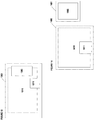
- an interface 1300 can have an overlaid representation portion 1310, a global selection portion 1311, and a control menu 1360, all on a single interface 1300. It is also possible, as depicted in FIG. 14 , that two separate sub-interfaces 1400 and 1401 may be used.
- the control menu 1460 may be on interface portion 1401 and the overlaid representation portion 1410 and global selection portion 1411 may be on interface portion 1400.
- These various interface portions may be shown on separate screens, on separate displays or in separate windows. Other configurations of the various portions on various displays or in various windows may also be used.
- computer 210, display 220, and / or input device 230 may each be separate computing devices, applications, or processes or may run as part of the same computing devices, applications, or processes - or one of more may be combined to run as part of one application or process - and / or each or one or more may be part of or run on computing devices.
- Computing devices may include a bus or other communication mechanism for communicating information, and a processor coupled with the bus for processing information.
- the computing devices may have a main memory, such as a random access memory or other dynamic storage device, coupled to the bus. The main memory may be used to store instructions and temporary variables.
- the computing devices may also include a read-only memory or other static storage device coupled to the bus for storing static information and instructions.
- the computer systems may also be coupled to a display, such as a CRT or LCD monitor.
- Input devices may also be coupled to the computing devices. These input devices may include a mouse, a trackball, or cursor direction keys.
- Each computing device may be implemented using one or more physical computers, processors, embedded devices, or computer systems or a combination or portions thereof.
- the instructions executed by the computing device may also be read in from a computer-readable medium.
- the computer-readable medium may be a CD, DVD, optical or magnetic disk, laserdisc, carrier wave, or any other medium that is readable by the computing device.
- hardwired circuitry may be used in place of or in combination with software instructions executed by the processor. Communication among modules, systems, devices, and elements may be over direct or switched connections, and wired or wireless networks or connections, via directly connected wires, or any other appropriate communication mechanism.
- the communication among modules, systems, devices, and elements may include handshaking, notifications, coordination, encapsulation, encryption, headers, such as routing or error detecting headers, or any other appropriate communication protocol or attribute.
- Communication may also messages related to HTTP, HTTPS, FTP, TCP, IP, ebMS OASIS/ebXML, secure sockets, VPN, encrypted or unencrypted pipes, MIME, SMTP, MIME Multipart/Related Content-type, SQL, etc.
- Any appropriate 3D graphics processing may be used for displaying or rendering, including processing based on OpenGL, Direct3D, Java 3D, etc.
- Whole, partial, or modified 3D graphics packages may also be used, such packages including 3DS Max, SolidWorks, Maya, Form Z, Cybermotion 3D, or any others.
- various parts of the needed rendering may occur on traditional or specialized graphics hardware.
- the rendering may also occur on the general CPU, on programmable hardware, on a separate processor, be distributed over multiple processors, over multiple dedicated graphics cards, or using any other appropriate combination of hardware or technique.
- All of the methods and processes described above may be embodied in, and fully automated via, software code modules executed by one or more general purpose computers or processors, such as those computer systems described above.
- the code modules may be stored in any type of computer-readable medium or other computer storage device. Some or all of the methods may alternatively be embodied in specialized computer hardware.
Claims (20)
- Procédé mis en oeuvre par ordinateur pour l'ajustement de prothèses dentaires basé sur le tissu mou, comprenant :la réception (310) d'un balayage 3D du tissu mou du patient, ledit balayage 3D du tissu mou du patient comprenant au moins une partie d'émergence, ladite partie d'émergence du balayage 3D du tissu mou s'étendant d'une zone associée à un implant fixé audit patient, à une zone où une prothèse dentaire fixée audit implant émergerait dudit tissu mou ;la réception (330) d'informations de limite d'émergence pour une surface d'émergence d'un modèle 3D de la prothèse dentaire ;la réception (340) d'informations de décalage souhaitées pour la surface d'émergence du modèle 3D de la prothèse dentaire, dans lequel les informations de décalage comprennent une distance entre la surface d'émergence du modèle 3D de la prothèse dentaire et la partie d'émergence du balayage 3D du tissu mou ;la détermination (350), en utilisant un ou plusieurs dispositifs informatiques, d'une forme de la surface d'émergence du modèle 3D de la prothèse dentaire sur la base de la partie d'émergence du balayage 3D du tissu mou, des informations de limite d'émergence et des informations de décalage ;la modification en outre de la surface d'émergence en manipulant des manipulateurs (950, 951, 970, 971) de la prothèse dentaire, dans lequel les manipulateurs sont magnétisés, de sorte qu'un opérateur peut changer la surface d'émergence tout en maintenant ladite distance entre la surface d'émergence du modèle 3D de la prothèse dentaire et le balayage 3D du tissu mou, sauf si un manipulateur desdits manipulateurs est déplacé au-delà d'une distance de magnétisation seuil prédéterminée, auquel cas le manipulateur se déplace librement et la surface d'émergence est manipulée librement et ne se limite pas au décalage avec le balayage 3D du tissu mou, sinon le manipulateur est maintenu au décalage souhaité avec le balayage 3D du tissu mou ; etla production (360) de données de fabrication liées à la prothèse dentaire.
- Procédé selon la revendication 1, dans lequel la détermination de la surface d'émergence du modèle 3D de la prothèse dentaire comprend la détermination d'une surface 3D décalée par rapport à la partie d'émergence du balayage 3D du tissu mou par un décalage associé aux informations de décalage souhaitées.
- Procédé selon la revendication 1, dans lequel la détermination de la surface d'émergence du modèle 3D de la prothèse dentaire comprend la détermination d'une surface du modèle 3D de la prothèse approximativement de la zone associée à l'implant à approximativement une limite d'émergence associée aux informations de limite d'émergence.
- Procédé selon la revendication 1, dans lequel la détermination de la surface d'émergence du modèle 3D de la prothèse dentaire comprend la détermination de la surface du modèle 3D d'une butée.
- Procédé selon la revendication 1, dans lequel la réception d'informations de décalage souhaitées comprend la réception d'informations pour étendre la surface d'émergence du modèle 3D de la prothèse dentaire au-delà, dans une direction radiale, de la partie d'émergence du balayage 3D du tissu mou.
- Procédé selon la revendication 1, dans lequel la réception d'informations de décalage souhaitées comprend la réception d'informations pour fournir un espace entre la surface d'émergence du modèle 3D de la prothèse dentaire et la partie d'émergence du balayage 3D du tissu mou.
- Procédé selon la revendication 1, dans lequel le procédé comprend en outre la réception d'informations de placement pour le modèle 3D de la prothèse dentaire par rapport au balayage 3D du tissu mou.
- Procédé selon la revendication 1, dans lequel la réception des informations de limite d'émergence comprend la réception d'informations de placement pour une ligne de marge sur la surface 3D du tissu mou en provenance d'un opérateur.
- Procédé selon la revendication 8, dans lequel la détermination de la surface d'émergence du modèle 3D de la prothèse dentaire comprend la détermination d' une surface 3D pour la prothèse dentaire de la base de la prothèse jusqu'à la ligne de marge.
- Procédé selon la revendication 1, dans lequel la réception d'informations de placement pour une prothèse dentaire comprend la réception d'un axe central pour la prothèse dentaire ; et dans lequel la détermination de la surface d'émergence du modèle 3D de la prothèse dentaire comprend la détermination de la surface d'émergence du modèle 3D de la prothèse dentaire sur la base au moins en partie de l'axe central pour la prothèse dentaire.
- Système d'ajustement de prothèses dentaires basé sur le tissu mou, comprenant un ou plusieurs dispositifs informatiques, lesdits un ou plusieurs dispositifs informatiques étant conçus pour :recevoir un balayage 3D du tissu mou du patient, ledit balayage 3D du tissu mou du patient comprenant au moins une partie d'émergence, ladite partie d'émergence du balayage 3D du tissu mou s'étendant d'une zone associée à un implant fixé audit patient, à une zone où une prothèse dentaire fixée audit implant émergerait dudit tissu mou ;recevoir des informations de limite d'émergence pour une surface d'émergence d'un modèle 3D de la prothèse dentaire ;recevoir des informations de décalage souhaitées pour la surface d'émergence du modèle 3D de la prothèse dentaire, dans lequel les informations de décalage comprennent une distance entre la surface d'émergence du modèle 3D de la prothèse dentaire et la partie d'émergence du balayage 3D du tissu mou ;déterminer une forme de la surface d'émergence du modèle 3D de la prothèse dentaire sur la base de la partie d'émergence du balayage 3D du tissu mou, des informations de limite d'émergence et des informations de décalage ;dans lequel la surface d'émergence du modèle 3D est en outre modifiée en manipulant des manipulateurs (950, 951, 970, 971) du modèle 3D de la prothèse dentaire, dans lequel les manipulateurs sont magnétisés, de sorte qu'un opérateur peut changer la surface d'émergence du modèle 3D tout en maintenant ladite distance entre la surface d'émergence du modèle 3D de la prothèse dentaire et le balayage 3D du tissu mou, sauf si un manipulateur desdits manipulateurs est déplacé au-delà d'une distance de magnétisation seuil prédéterminée, auquel cas le manipulateur se déplace librement et la surface d'émergence est manipulée librement et ne se limite pas au décalage avec le balayage 3D du tissu mou, sinon le manipulateur est maintenu au décalage souhaité avec le balayage 3D du tissu mou ; etproduire des données de fabrication liées à la prothèse dentaire.
- Système selon la revendication 11, dans lequel la détermination de la surface d'émergence du modèle 3D de la prothèse dentaire comprend la détermination d'une surface 3D décalée par rapport à la partie d'émergence du balayage 3D du tissu mou par un décalage associé aux informations de décalage souhaitées.
- Système selon la revendication 11, dans lequel la détermination de la surface d'émergence du modèle 3D de la prothèse dentaire comprend la détermination d'une surface du modèle 3D de la prothèse approximativement de la zone associée à l'implant à approximativement une limite d'émergence associée aux informations de limite d'émergence.
- Système selon la revendication 11, dans lequel la réception d'informations de décalage souhaitées comprend la réception d'informations pour étendre la surface d'émergence du modèle 3D de la prothèse dentaire au-delà, dans une direction radiale, de la partie d'émergence du balayage 3D du tissu mou.
- Système selon la revendication 11, dans lequel la réception d'informations de décalage souhaitées comprend la réception d'informations pour fournir un espace entre la surface d'émergence du modèle 3D de la prothèse dentaire et la partie d'émergence du balayage 3D du tissu mou.
- Support de stockage lisible par ordinateur comprenant des instructions exécutables par ordinateur pour l'ajustement de prothèses dentaires basé sur le tissu mou, lesdites instructions exécutables par ordinateur, lorsqu'elles sont exécutées sur un ou plusieurs dispositifs informatiques, mettant en oeuvre un procédé comprenant :la réception d'un balayage 3D du tissu mou du patient, ledit balayage 3D du tissu mou du patient comprenant au moins une partie d'émergence, ladite partie d'émergence du balayage 3D du tissu mou s'étendant d'une zone associée à un implant fixé audit patient, à une zone où une prothèse dentaire fixée audit implant émergerait dudit tissu mou ;la réception d'informations de limite d'émergence pour une surface d'émergence d'un modèle 3D de la prothèse dentaire ;la réception d'informations de décalage souhaitées pour la surface d'émergence du modèle 3D de la prothèse dentaire, dans lequel les informations de décalage comprennent une distance entre la surface d'émergence du modèle 3D de la prothèse dentaire et la partie d'émergence du balayage 3D du tissu mou ;la détermination, en utilisant un ou plusieurs dispositifs informatiques, d'une forme de la surface d'émergence du modèle 3D de la prothèse dentaire sur la base de la partie d'émergence du balayage 3D du tissu mou, des informations de limite d'émergence et des informations de décalage ;la modification en outre de la surface d'émergence en manipulant des manipulateurs (950, 951, 970, 971) de la prothèse dentaire, dans lequel les manipulateurs sont magnétisés, de sorte qu'un opérateur peut changer la surface d'émergence tout en maintenant ladite distance entre la surface d'émergence du modèle 3D de la prothèse dentaire et le balayage 3D du tissu mou, sauf si un manipulateur desdits manipulateurs est déplacé au-delà d'une distance de magnétisation seuil prédéterminée, auquel cas le manipulateur se déplace librement et la surface d'émergence est manipulée librement et ne se limite pas au décalage avec le balayage 3D du tissu mou, sinon le manipulateur est maintenu au décalage souhaité avec le balayage 3D du tissu mou ; etla production de données de fabrication liées à la prothèse dentaire.
- Support de stockage lisible par ordinateur selon la revendication 16, dans lequel la détermination de la surface d'émergence du modèle 3D de la prothèse dentaire comprend la détermination d'une surface 3D décalée par rapport à la partie d'émergence du balayage 3D du tissu mou par un décalage associé aux informations de décalage souhaitées.
- Support de stockage lisible par ordinateur selon la revendication 16, dans lequel la détermination de la surface d'émergence du modèle 3D de la prothèse dentaire comprend la détermination d'une surface du modèle 3D de la prothèse approximativement de la zone associée à l'implant à approximativement une limite d'émergence associée aux informations de limite d'émergence.
- Support de stockage lisible par ordinateur selon la revendication 16, dans lequel la réception d'informations de décalage souhaitées comprend la réception d'informations pour étendre la surface d'émergence du modèle 3D de la prothèse dentaire au-delà, dans une direction radiale, de la partie d'émergence du balayage 3D du tissu mou.
- Support de stockage lisible par ordinateur selon la revendication 16, dans lequel la réception d'informations de décalage souhaitées comprend la réception d'informations pour fournir un espace entre la surface d'émergence du modèle 3D de la prothèse dentaire et la partie d'émergence du balayage 3D du tissu mou.
Applications Claiming Priority (2)
| Application Number | Priority Date | Filing Date | Title |
|---|---|---|---|
| US12/885,027 US8712733B2 (en) | 2010-09-17 | 2010-09-17 | Adjusting dental prostheses based on soft tissue |
| PCT/IB2011/002774 WO2012035441A2 (fr) | 2010-09-17 | 2011-09-13 | Ajustement de prothèses dentaires basé sur le tissu mou |
Publications (3)
| Publication Number | Publication Date |
|---|---|
| EP2615999A2 EP2615999A2 (fr) | 2013-07-24 |
| EP2615999A4 EP2615999A4 (fr) | 2014-04-02 |
| EP2615999B1 true EP2615999B1 (fr) | 2018-03-14 |
Family
ID=44674747
Family Applications (1)
| Application Number | Title | Priority Date | Filing Date |
|---|---|---|---|
| EP11824659.4A Active EP2615999B1 (fr) | 2010-09-17 | 2011-09-13 | Ajustement de prothèses dentaires basé sur le tissu mou |
Country Status (7)
| Country | Link |
|---|---|
| US (1) | US8712733B2 (fr) |
| EP (1) | EP2615999B1 (fr) |
| JP (1) | JP6073226B2 (fr) |
| CA (1) | CA2808722C (fr) |
| DK (1) | DK2615999T3 (fr) |
| ES (1) | ES2666354T3 (fr) |
| WO (1) | WO2012035441A2 (fr) |
Families Citing this family (20)
| Publication number | Priority date | Publication date | Assignee | Title |
|---|---|---|---|---|
| US9934360B2 (en) * | 2010-02-10 | 2018-04-03 | Biocad Medical, Inc. | Dental data planning |
| US9179988B2 (en) | 2010-05-25 | 2015-11-10 | Biocad Medical, Inc. | Dental prosthesis connector design |
| CA2863675C (fr) | 2011-02-11 | 2019-04-23 | E4 Endeavors, Inc. | Systeme et procede de modelisation de specimen de biopsie |
| WO2012113407A1 (fr) * | 2011-02-23 | 2012-08-30 | 3Shape A/S | Procédé de modification de la partie gingivale d'un modèle virtuel d'un ensemble de dents |
| US9037439B2 (en) * | 2011-05-13 | 2015-05-19 | Align Technology, Inc. | Prioritization of three dimensional dental elements |
| US10595970B2 (en) | 2012-01-10 | 2020-03-24 | Esthetic Implant Solutions, Llc | Bonding of soft gingival tissues with anatomical and other dental prostheses |
| US11253345B2 (en) | 2012-01-10 | 2022-02-22 | Esthetic Implant Solutions, Llc | Methods for integrating scans including 3D cone beam scan for positioning of implant and fabrication of dental prosthesis |
| US10709525B2 (en) | 2012-01-10 | 2020-07-14 | Esthetic Implant Solutions, Llc | Methods for taking an oral scan without requiring removal of a temporary healing abutment |
| EP3395287B1 (fr) | 2012-02-14 | 2020-07-01 | 3Shape A/S | Modélisation d'une conception numérique d'une prothèse dentaire |
| US9198627B2 (en) | 2012-04-16 | 2015-12-01 | Biomet 3i | System and method for improved intra-oral scanning protocol and calibration |
| EP3954324A1 (fr) | 2012-11-20 | 2022-02-16 | Advanced Implant Intellectual Properties, LLC | Méthode digitale de fabrication d'un composant dentaire |
| EP3094283A4 (fr) * | 2013-12-20 | 2018-01-24 | Biomet 3i, LLC | Système dentaire pour développer des prothèses sur mesure par balayage d'éléments codés |
| WO2016102451A1 (fr) * | 2014-12-22 | 2016-06-30 | 3Shape A/S | Utilisation d'un scan osseux par cbct (tomographie volumique à faisceau ouvert conique) pour concevoir un col implantaire dentaire |
| GB201708520D0 (en) | 2017-05-27 | 2017-07-12 | Dawood Andrew | A method for reducing artefact in intra oral scans |
| US11559379B2 (en) | 2018-04-12 | 2023-01-24 | Esthetic Implant Solutions, Llc | Dental implants with markers for determining three-dimensional positioning |
| EP3679887A1 (fr) * | 2019-01-09 | 2020-07-15 | Egs S.R.L | Procédé et dispositif de conception d'une butée |
| CN110136563B (zh) * | 2019-05-31 | 2021-09-03 | 何东广 | 可卷曲的软体地形模型沙盘及其制备方法 |
| AT522914A1 (de) * | 2019-09-03 | 2021-03-15 | Eap® Produktions Und Patentverwertungs Gmbh | Verfahren zur Herstellung eines Computermodells für ein Abutment und eines Abutments |
| US11273016B2 (en) * | 2019-11-29 | 2022-03-15 | Dio Corporation | Method of manufacturing digital overdenture and holder abutment mounting guide and fixing bar bending apparatus for holder device applied thereto |
| CN111524065B (zh) * | 2020-03-12 | 2023-05-23 | 浙江工业大学 | 一种基于牙冠的种植牙个性化基台自动生成方法 |
Family Cites Families (36)
| Publication number | Priority date | Publication date | Assignee | Title |
|---|---|---|---|---|
| US5273429A (en) | 1992-04-03 | 1993-12-28 | Foster-Miller, Inc. | Method and apparatus for modeling a dental prosthesis |
| US5674069A (en) | 1995-01-13 | 1997-10-07 | Osorio; Julian | Customized dental abutment |
| JPH1075963A (ja) * | 1996-09-06 | 1998-03-24 | Nikon Corp | 歯科補綴物モデルの設計方法およびこの方法を実行するプログラムを記録した媒体 |
| US6217334B1 (en) | 1997-01-28 | 2001-04-17 | Iris Development Corporation | Dental scanning method and apparatus |
| US5975893A (en) | 1997-06-20 | 1999-11-02 | Align Technology, Inc. | Method and system for incrementally moving teeth |
| US6409504B1 (en) * | 1997-06-20 | 2002-06-25 | Align Technology, Inc. | Manipulating a digital dentition model to form models of individual dentition components |
| US5989029A (en) | 1997-07-08 | 1999-11-23 | Atlantis Components, Inc. | Customized dental abutments and methods of preparing or selecting the same |
| US6514074B1 (en) * | 1999-05-14 | 2003-02-04 | Align Technology, Inc. | Digitally modeling the deformation of gingival |
| AU2607301A (en) * | 1999-12-29 | 2001-07-09 | Ormco Corporation | Custom orthodontic appliance forming method and apparatus |
| US7471821B2 (en) * | 2000-04-28 | 2008-12-30 | Orametrix, Inc. | Method and apparatus for registering a known digital object to scanned 3-D model |
| US20020110786A1 (en) | 2001-02-09 | 2002-08-15 | Dillier Stephen L. | Method and apparatus for generating a customized dental prosthetic |
| US6767208B2 (en) | 2002-01-10 | 2004-07-27 | Align Technology, Inc. | System and method for positioning teeth |
| US7112065B2 (en) * | 2002-07-22 | 2006-09-26 | Cadent Ltd. | Method for defining a finish line of a dental prosthesis |
| DE10252298B3 (de) * | 2002-11-11 | 2004-08-19 | Mehl, Albert, Prof. Dr. Dr. | Verfahren zur Herstellung von Zahnersatzteilen oder Zahnrestaurationen unter Verwendung elektronischer Zahndarstellungen |
| DE10312848A1 (de) | 2003-03-21 | 2004-10-07 | Sirona Dental Systems Gmbh | Datenbank, Zahnmodell und Zahnersatzteil, aufgebaut aus digitalisierten Abbildungen realer Zähne |
| DE10313690B4 (de) | 2003-03-26 | 2013-08-22 | 3M Deutschland Gmbh | Verarbeitung von Gestaltdaten einer Dentalprothese |
| US7228191B2 (en) * | 2003-05-02 | 2007-06-05 | Geodigm Corporation | Method and apparatus for constructing crowns, bridges and implants for dental use |
| US7245753B2 (en) * | 2003-06-26 | 2007-07-17 | Carestream Health, Inc. | Method for determining dental alignment using radiographs |
| US7333874B2 (en) * | 2004-02-24 | 2008-02-19 | Cadent Ltd. | Method and system for designing and producing dental prostheses and appliances |
| DE102004038136B4 (de) | 2004-07-08 | 2019-06-13 | Sirona Dental Systems Gmbh | Verfahren zur Konstruktion der Oberfläche eines aus dreidimensionalen Daten bestehenden Zahnersatzteils |
| EP1629793A1 (fr) * | 2004-08-25 | 2006-03-01 | Remedent NV | Appareils dentaires |
| US7762814B2 (en) | 2004-09-14 | 2010-07-27 | Oratio B.V. | Method of manufacturing and installing a ceramic dental implant with an aesthetic implant abutment |
| US7695281B2 (en) | 2004-11-12 | 2010-04-13 | 3M Innovative Properties Company | Method and system for designing a dental replacement |
| US7862336B2 (en) * | 2004-11-26 | 2011-01-04 | Cadent Ltd. | Method and system for providing feedback data useful in prosthodontic procedures associated with the intra oral cavity |
| US7236842B2 (en) * | 2004-12-02 | 2007-06-26 | Cadent Ltd. | System and method for manufacturing a dental prosthesis and a dental prosthesis manufactured thereby |
| DE102005011066A1 (de) * | 2005-03-08 | 2006-09-14 | Sirona Dental Systems Gmbh | Verfahren zur Herstellung der Lageübereinstimmung von 3D-Datensätzen in einem dentalen CAD/CAM-System |
| JP5021660B2 (ja) * | 2005-10-24 | 2012-09-12 | バイオメット・3アイ・エルエルシー | 歯科用インプラント構成要素を製造するための方法 |
| US7698014B2 (en) | 2006-01-20 | 2010-04-13 | 3M Innovative Properties Company | Local enforcement of accuracy in fabricated models |
| DE102007002144A1 (de) * | 2007-01-15 | 2008-07-17 | Aepsilon Rechteverwaltungs Gmbh | Verfahren betreffend Implantate sowie ein computerlesbares Medium und ein Computer |
| AU2008238423B2 (en) * | 2007-04-17 | 2013-10-10 | Indi Implant Systems Gmbh | Dental implant system |
| KR100795645B1 (ko) * | 2007-08-17 | 2008-01-17 | 김정한 | 임플란트용 일체형 어버트먼트 제조방법 |
| EP2227172B1 (fr) | 2007-11-28 | 2018-04-18 | 3M Innovative Properties Company | Fabrication d'articles dentaires au moyen de processus de réduction et d'addition à commande numérique |
| KR20100126700A (ko) * | 2008-01-23 | 2010-12-02 | 센서블 테크놀로지스, 인크. | 햅티컬 작동가능한 치아 모델링 시스템 |
| EP2361052A1 (fr) * | 2008-09-18 | 2011-08-31 | 3Shape A/S | Instruments de conception personnalisee de restaurations dentaires |
| US20100105011A1 (en) * | 2008-10-29 | 2010-04-29 | Inpronto Inc. | System, Method And Apparatus For Tooth Implant Planning And Tooth Implant Kits |
| DE102009003650A1 (de) * | 2009-03-20 | 2010-09-30 | Degudent Gmbh | Verfahren zum Herstellen eines Abutments |
-
2010
- 2010-09-17 US US12/885,027 patent/US8712733B2/en active Active
-
2011
- 2011-09-13 ES ES11824659.4T patent/ES2666354T3/es active Active
- 2011-09-13 CA CA2808722A patent/CA2808722C/fr active Active
- 2011-09-13 WO PCT/IB2011/002774 patent/WO2012035441A2/fr active Application Filing
- 2011-09-13 DK DK11824659.4T patent/DK2615999T3/en active
- 2011-09-13 EP EP11824659.4A patent/EP2615999B1/fr active Active
- 2011-09-13 JP JP2013528787A patent/JP6073226B2/ja active Active
Non-Patent Citations (1)
| Title |
|---|
| None * |
Also Published As
| Publication number | Publication date |
|---|---|
| CA2808722A1 (fr) | 2012-03-22 |
| JP6073226B2 (ja) | 2017-02-01 |
| JP2013537816A (ja) | 2013-10-07 |
| DK2615999T3 (en) | 2018-04-16 |
| EP2615999A2 (fr) | 2013-07-24 |
| WO2012035441A2 (fr) | 2012-03-22 |
| WO2012035441A3 (fr) | 2012-05-18 |
| CA2808722C (fr) | 2018-08-07 |
| US8712733B2 (en) | 2014-04-29 |
| ES2666354T3 (es) | 2018-05-04 |
| EP2615999A4 (fr) | 2014-04-02 |
| US20120072178A1 (en) | 2012-03-22 |
Similar Documents
| Publication | Publication Date | Title |
|---|---|---|
| EP2615999B1 (fr) | Ajustement de prothèses dentaires basé sur le tissu mou | |
| EP2615998B1 (fr) | Manipulation d'une prothèse dans la conception de prothèses dentaires | |
| US10314674B2 (en) | Dental prosthetics manipulation, selection, and planning | |
| US8949730B2 (en) | Library selection in dental prosthesis design | |
| US10891403B2 (en) | Occlusion estimation in dental prosthesis design | |
| US9792413B2 (en) | Electronic dental charting | |
| JP2013537816A5 (fr) | ||
| US9179988B2 (en) | Dental prosthesis connector design | |
| US9089387B2 (en) | Surface manipulation in dental prosthesis design | |
| EP2595564B1 (fr) | Manipulation de surface en conception de prothèse dentaire | |
| US10090070B2 (en) | Electronic dental charting |
Legal Events
| Date | Code | Title | Description |
|---|---|---|---|
| PUAI | Public reference made under article 153(3) epc to a published international application that has entered the european phase |
Free format text: ORIGINAL CODE: 0009012 |
|
| 17P | Request for examination filed |
Effective date: 20130417 |
|
| AK | Designated contracting states |
Kind code of ref document: A2 Designated state(s): AL AT BE BG CH CY CZ DE DK EE ES FI FR GB GR HR HU IE IS IT LI LT LU LV MC MK MT NL NO PL PT RO RS SE SI SK SM TR |
|
| DAX | Request for extension of the european patent (deleted) | ||
| A4 | Supplementary search report drawn up and despatched |
Effective date: 20140303 |
|
| RIC1 | Information provided on ipc code assigned before grant |
Ipc: A61C 13/34 20060101ALI20140225BHEP Ipc: A61C 13/00 20060101AFI20140225BHEP Ipc: G06F 19/00 20110101ALI20140225BHEP Ipc: A61C 19/04 20060101ALI20140225BHEP |
|
| GRAP | Despatch of communication of intention to grant a patent |
Free format text: ORIGINAL CODE: EPIDOSNIGR1 |
|
| INTG | Intention to grant announced |
Effective date: 20171002 |
|
| GRAS | Grant fee paid |
Free format text: ORIGINAL CODE: EPIDOSNIGR3 |
|
| GRAA | (expected) grant |
Free format text: ORIGINAL CODE: 0009210 |
|
| AK | Designated contracting states |
Kind code of ref document: B1 Designated state(s): AL AT BE BG CH CY CZ DE DK EE ES FI FR GB GR HR HU IE IS IT LI LT LU LV MC MK MT NL NO PL PT RO RS SE SI SK SM TR |
|
| REG | Reference to a national code |
Ref country code: GB Ref legal event code: FG4D |
|
| REG | Reference to a national code |
Ref country code: CH Ref legal event code: EP Ref country code: AT Ref legal event code: REF Ref document number: 978106 Country of ref document: AT Kind code of ref document: T Effective date: 20180315 |
|
| REG | Reference to a national code |
Ref country code: IE Ref legal event code: FG4D |
|
| REG | Reference to a national code |
Ref country code: DE Ref legal event code: R096 Ref document number: 602011046556 Country of ref document: DE |
|
| REG | Reference to a national code |
Ref country code: DK Ref legal event code: T3 Effective date: 20180411 |
|
| REG | Reference to a national code |
Ref country code: SE Ref legal event code: TRGR |
|
| REG | Reference to a national code |
Ref country code: ES Ref legal event code: FG2A Ref document number: 2666354 Country of ref document: ES Kind code of ref document: T3 Effective date: 20180504 |
|
| REG | Reference to a national code |
Ref country code: NL Ref legal event code: MP Effective date: 20180314 |
|
| REG | Reference to a national code |
Ref country code: LT Ref legal event code: MG4D |
|
| PG25 | Lapsed in a contracting state [announced via postgrant information from national office to epo] |
Ref country code: NO Free format text: LAPSE BECAUSE OF FAILURE TO SUBMIT A TRANSLATION OF THE DESCRIPTION OR TO PAY THE FEE WITHIN THE PRESCRIBED TIME-LIMIT Effective date: 20180614 Ref country code: HR Free format text: LAPSE BECAUSE OF FAILURE TO SUBMIT A TRANSLATION OF THE DESCRIPTION OR TO PAY THE FEE WITHIN THE PRESCRIBED TIME-LIMIT Effective date: 20180314 Ref country code: CY Free format text: LAPSE BECAUSE OF FAILURE TO SUBMIT A TRANSLATION OF THE DESCRIPTION OR TO PAY THE FEE WITHIN THE PRESCRIBED TIME-LIMIT Effective date: 20180314 Ref country code: LT Free format text: LAPSE BECAUSE OF FAILURE TO SUBMIT A TRANSLATION OF THE DESCRIPTION OR TO PAY THE FEE WITHIN THE PRESCRIBED TIME-LIMIT Effective date: 20180314 Ref country code: FI Free format text: LAPSE BECAUSE OF FAILURE TO SUBMIT A TRANSLATION OF THE DESCRIPTION OR TO PAY THE FEE WITHIN THE PRESCRIBED TIME-LIMIT Effective date: 20180314 |
|
| REG | Reference to a national code |
Ref country code: AT Ref legal event code: MK05 Ref document number: 978106 Country of ref document: AT Kind code of ref document: T Effective date: 20180314 |
|
| REG | Reference to a national code |
Ref country code: FR Ref legal event code: PLFP Year of fee payment: 8 |
|
| PG25 | Lapsed in a contracting state [announced via postgrant information from national office to epo] |
Ref country code: GR Free format text: LAPSE BECAUSE OF FAILURE TO SUBMIT A TRANSLATION OF THE DESCRIPTION OR TO PAY THE FEE WITHIN THE PRESCRIBED TIME-LIMIT Effective date: 20180615 Ref country code: LV Free format text: LAPSE BECAUSE OF FAILURE TO SUBMIT A TRANSLATION OF THE DESCRIPTION OR TO PAY THE FEE WITHIN THE PRESCRIBED TIME-LIMIT Effective date: 20180314 Ref country code: RS Free format text: LAPSE BECAUSE OF FAILURE TO SUBMIT A TRANSLATION OF THE DESCRIPTION OR TO PAY THE FEE WITHIN THE PRESCRIBED TIME-LIMIT Effective date: 20180314 Ref country code: BG Free format text: LAPSE BECAUSE OF FAILURE TO SUBMIT A TRANSLATION OF THE DESCRIPTION OR TO PAY THE FEE WITHIN THE PRESCRIBED TIME-LIMIT Effective date: 20180614 |
|
| PG25 | Lapsed in a contracting state [announced via postgrant information from national office to epo] |
Ref country code: PL Free format text: LAPSE BECAUSE OF FAILURE TO SUBMIT A TRANSLATION OF THE DESCRIPTION OR TO PAY THE FEE WITHIN THE PRESCRIBED TIME-LIMIT Effective date: 20180314 Ref country code: EE Free format text: LAPSE BECAUSE OF FAILURE TO SUBMIT A TRANSLATION OF THE DESCRIPTION OR TO PAY THE FEE WITHIN THE PRESCRIBED TIME-LIMIT Effective date: 20180314 Ref country code: AL Free format text: LAPSE BECAUSE OF FAILURE TO SUBMIT A TRANSLATION OF THE DESCRIPTION OR TO PAY THE FEE WITHIN THE PRESCRIBED TIME-LIMIT Effective date: 20180314 Ref country code: NL Free format text: LAPSE BECAUSE OF FAILURE TO SUBMIT A TRANSLATION OF THE DESCRIPTION OR TO PAY THE FEE WITHIN THE PRESCRIBED TIME-LIMIT Effective date: 20180314 Ref country code: RO Free format text: LAPSE BECAUSE OF FAILURE TO SUBMIT A TRANSLATION OF THE DESCRIPTION OR TO PAY THE FEE WITHIN THE PRESCRIBED TIME-LIMIT Effective date: 20180314 |
|
| PG25 | Lapsed in a contracting state [announced via postgrant information from national office to epo] |
Ref country code: AT Free format text: LAPSE BECAUSE OF FAILURE TO SUBMIT A TRANSLATION OF THE DESCRIPTION OR TO PAY THE FEE WITHIN THE PRESCRIBED TIME-LIMIT Effective date: 20180314 Ref country code: CZ Free format text: LAPSE BECAUSE OF FAILURE TO SUBMIT A TRANSLATION OF THE DESCRIPTION OR TO PAY THE FEE WITHIN THE PRESCRIBED TIME-LIMIT Effective date: 20180314 Ref country code: SK Free format text: LAPSE BECAUSE OF FAILURE TO SUBMIT A TRANSLATION OF THE DESCRIPTION OR TO PAY THE FEE WITHIN THE PRESCRIBED TIME-LIMIT Effective date: 20180314 Ref country code: SM Free format text: LAPSE BECAUSE OF FAILURE TO SUBMIT A TRANSLATION OF THE DESCRIPTION OR TO PAY THE FEE WITHIN THE PRESCRIBED TIME-LIMIT Effective date: 20180314 |
|
| REG | Reference to a national code |
Ref country code: DE Ref legal event code: R097 Ref document number: 602011046556 Country of ref document: DE |
|
| PG25 | Lapsed in a contracting state [announced via postgrant information from national office to epo] |
Ref country code: PT Free format text: LAPSE BECAUSE OF FAILURE TO SUBMIT A TRANSLATION OF THE DESCRIPTION OR TO PAY THE FEE WITHIN THE PRESCRIBED TIME-LIMIT Effective date: 20180716 |
|
| PLBE | No opposition filed within time limit |
Free format text: ORIGINAL CODE: 0009261 |
|
| STAA | Information on the status of an ep patent application or granted ep patent |
Free format text: STATUS: NO OPPOSITION FILED WITHIN TIME LIMIT |
|
| 26N | No opposition filed |
Effective date: 20181217 |
|
| PG25 | Lapsed in a contracting state [announced via postgrant information from national office to epo] |
Ref country code: SI Free format text: LAPSE BECAUSE OF FAILURE TO SUBMIT A TRANSLATION OF THE DESCRIPTION OR TO PAY THE FEE WITHIN THE PRESCRIBED TIME-LIMIT Effective date: 20180314 |
|
| PG25 | Lapsed in a contracting state [announced via postgrant information from national office to epo] |
Ref country code: MC Free format text: LAPSE BECAUSE OF FAILURE TO SUBMIT A TRANSLATION OF THE DESCRIPTION OR TO PAY THE FEE WITHIN THE PRESCRIBED TIME-LIMIT Effective date: 20180314 |
|
| REG | Reference to a national code |
Ref country code: IE Ref legal event code: MM4A |
|
| PG25 | Lapsed in a contracting state [announced via postgrant information from national office to epo] |
Ref country code: LU Free format text: LAPSE BECAUSE OF NON-PAYMENT OF DUE FEES Effective date: 20180913 |
|
| PG25 | Lapsed in a contracting state [announced via postgrant information from national office to epo] |
Ref country code: IE Free format text: LAPSE BECAUSE OF NON-PAYMENT OF DUE FEES Effective date: 20180913 |
|
| PG25 | Lapsed in a contracting state [announced via postgrant information from national office to epo] |
Ref country code: MT Free format text: LAPSE BECAUSE OF NON-PAYMENT OF DUE FEES Effective date: 20180913 |
|
| PGFP | Annual fee paid to national office [announced via postgrant information from national office to epo] |
Ref country code: ES Payment date: 20191008 Year of fee payment: 9 |
|
| PG25 | Lapsed in a contracting state [announced via postgrant information from national office to epo] |
Ref country code: TR Free format text: LAPSE BECAUSE OF FAILURE TO SUBMIT A TRANSLATION OF THE DESCRIPTION OR TO PAY THE FEE WITHIN THE PRESCRIBED TIME-LIMIT Effective date: 20180314 |
|
| PG25 | Lapsed in a contracting state [announced via postgrant information from national office to epo] |
Ref country code: HU Free format text: LAPSE BECAUSE OF FAILURE TO SUBMIT A TRANSLATION OF THE DESCRIPTION OR TO PAY THE FEE WITHIN THE PRESCRIBED TIME-LIMIT; INVALID AB INITIO Effective date: 20110913 |
|
| PG25 | Lapsed in a contracting state [announced via postgrant information from national office to epo] |
Ref country code: MK Free format text: LAPSE BECAUSE OF NON-PAYMENT OF DUE FEES Effective date: 20180314 |
|
| PG25 | Lapsed in a contracting state [announced via postgrant information from national office to epo] |
Ref country code: IS Free format text: LAPSE BECAUSE OF FAILURE TO SUBMIT A TRANSLATION OF THE DESCRIPTION OR TO PAY THE FEE WITHIN THE PRESCRIBED TIME-LIMIT Effective date: 20180714 |
|
| REG | Reference to a national code |
Ref country code: ES Ref legal event code: FD2A Effective date: 20230327 |
|
| PG25 | Lapsed in a contracting state [announced via postgrant information from national office to epo] |
Ref country code: ES Free format text: LAPSE BECAUSE OF NON-PAYMENT OF DUE FEES Effective date: 20200914 |
|
| P01 | Opt-out of the competence of the unified patent court (upc) registered |
Effective date: 20230516 |
|
| PGFP | Annual fee paid to national office [announced via postgrant information from national office to epo] |
Ref country code: DK Payment date: 20230627 Year of fee payment: 13 |
|
| PGFP | Annual fee paid to national office [announced via postgrant information from national office to epo] |
Ref country code: IT Payment date: 20230810 Year of fee payment: 13 Ref country code: GB Payment date: 20230720 Year of fee payment: 13 |
|
| REG | Reference to a national code |
Ref country code: GB Ref legal event code: 732E Free format text: REGISTERED BETWEEN 20231019 AND 20231025 |
|
| PGFP | Annual fee paid to national office [announced via postgrant information from national office to epo] |
Ref country code: SE Payment date: 20230710 Year of fee payment: 13 Ref country code: FR Payment date: 20230710 Year of fee payment: 13 Ref country code: DE Payment date: 20230718 Year of fee payment: 13 Ref country code: BE Payment date: 20230818 Year of fee payment: 13 |
|
| REG | Reference to a national code |
Ref country code: DE Ref legal event code: R081 Ref document number: 602011046556 Country of ref document: DE Owner name: SERVICES NOBEL BIOCARE PROCERA INC., CA Free format text: FORMER OWNER: BIOCAD MEDICAL INC., QUEBEC, CA |
|
| PGFP | Annual fee paid to national office [announced via postgrant information from national office to epo] |
Ref country code: CH Payment date: 20231001 Year of fee payment: 13 |
|
| REG | Reference to a national code |
Ref country code: BE Ref legal event code: PD Free format text: DETAILS ASSIGNMENT: CHANGE OF OWNER(S), MERGE Effective date: 20231121 |