EP2615212B1 - Hybridbaumaschine mit antriebsmotorsteuerung - Google Patents
Hybridbaumaschine mit antriebsmotorsteuerung Download PDFInfo
- Publication number
- EP2615212B1 EP2615212B1 EP11823388.1A EP11823388A EP2615212B1 EP 2615212 B1 EP2615212 B1 EP 2615212B1 EP 11823388 A EP11823388 A EP 11823388A EP 2615212 B1 EP2615212 B1 EP 2615212B1
- Authority
- EP
- European Patent Office
- Prior art keywords
- rotation speed
- engine
- calculating unit
- target
- power
- Prior art date
- Legal status (The legal status is an assumption and is not a legal conclusion. Google has not performed a legal analysis and makes no representation as to the accuracy of the status listed.)
- Not-in-force
Links
Images


Classifications
-
- G—PHYSICS
- G06—COMPUTING OR CALCULATING; COUNTING
- G06F—ELECTRIC DIGITAL DATA PROCESSING
- G06F17/00—Digital computing or data processing equipment or methods, specially adapted for specific functions
-
- B—PERFORMING OPERATIONS; TRANSPORTING
- B60—VEHICLES IN GENERAL
- B60W—CONJOINT CONTROL OF VEHICLE SUB-UNITS OF DIFFERENT TYPE OR DIFFERENT FUNCTION; CONTROL SYSTEMS SPECIALLY ADAPTED FOR HYBRID VEHICLES; ROAD VEHICLE DRIVE CONTROL SYSTEMS FOR PURPOSES NOT RELATED TO THE CONTROL OF A PARTICULAR SUB-UNIT
- B60W10/00—Conjoint control of vehicle sub-units of different type or different function
- B60W10/04—Conjoint control of vehicle sub-units of different type or different function including control of propulsion units
- B60W10/06—Conjoint control of vehicle sub-units of different type or different function including control of propulsion units including control of combustion engines
-
- E—FIXED CONSTRUCTIONS
- E02—HYDRAULIC ENGINEERING; FOUNDATIONS; SOIL SHIFTING
- E02F—DREDGING; SOIL-SHIFTING
- E02F9/00—Component parts of dredgers or soil-shifting machines, not restricted to one of the kinds covered by groups E02F3/00 - E02F7/00
- E02F9/20—Drives; Control devices
-
- B—PERFORMING OPERATIONS; TRANSPORTING
- B60—VEHICLES IN GENERAL
- B60W—CONJOINT CONTROL OF VEHICLE SUB-UNITS OF DIFFERENT TYPE OR DIFFERENT FUNCTION; CONTROL SYSTEMS SPECIALLY ADAPTED FOR HYBRID VEHICLES; ROAD VEHICLE DRIVE CONTROL SYSTEMS FOR PURPOSES NOT RELATED TO THE CONTROL OF A PARTICULAR SUB-UNIT
- B60W10/00—Conjoint control of vehicle sub-units of different type or different function
- B60W10/04—Conjoint control of vehicle sub-units of different type or different function including control of propulsion units
- B60W10/08—Conjoint control of vehicle sub-units of different type or different function including control of propulsion units including control of electric propulsion units, e.g. motors or generators
-
- B—PERFORMING OPERATIONS; TRANSPORTING
- B60—VEHICLES IN GENERAL
- B60W—CONJOINT CONTROL OF VEHICLE SUB-UNITS OF DIFFERENT TYPE OR DIFFERENT FUNCTION; CONTROL SYSTEMS SPECIALLY ADAPTED FOR HYBRID VEHICLES; ROAD VEHICLE DRIVE CONTROL SYSTEMS FOR PURPOSES NOT RELATED TO THE CONTROL OF A PARTICULAR SUB-UNIT
- B60W10/00—Conjoint control of vehicle sub-units of different type or different function
- B60W10/10—Conjoint control of vehicle sub-units of different type or different function including control of change-speed gearings
- B60W10/101—Infinitely variable gearings
- B60W10/103—Infinitely variable gearings of fluid type
-
- B—PERFORMING OPERATIONS; TRANSPORTING
- B60—VEHICLES IN GENERAL
- B60W—CONJOINT CONTROL OF VEHICLE SUB-UNITS OF DIFFERENT TYPE OR DIFFERENT FUNCTION; CONTROL SYSTEMS SPECIALLY ADAPTED FOR HYBRID VEHICLES; ROAD VEHICLE DRIVE CONTROL SYSTEMS FOR PURPOSES NOT RELATED TO THE CONTROL OF A PARTICULAR SUB-UNIT
- B60W10/00—Conjoint control of vehicle sub-units of different type or different function
- B60W10/30—Conjoint control of vehicle sub-units of different type or different function including control of auxiliary equipment, e.g. air-conditioning compressors or oil pumps
-
- B—PERFORMING OPERATIONS; TRANSPORTING
- B60—VEHICLES IN GENERAL
- B60W—CONJOINT CONTROL OF VEHICLE SUB-UNITS OF DIFFERENT TYPE OR DIFFERENT FUNCTION; CONTROL SYSTEMS SPECIALLY ADAPTED FOR HYBRID VEHICLES; ROAD VEHICLE DRIVE CONTROL SYSTEMS FOR PURPOSES NOT RELATED TO THE CONTROL OF A PARTICULAR SUB-UNIT
- B60W20/00—Control systems specially adapted for hybrid vehicles
-
- E—FIXED CONSTRUCTIONS
- E02—HYDRAULIC ENGINEERING; FOUNDATIONS; SOIL SHIFTING
- E02F—DREDGING; SOIL-SHIFTING
- E02F9/00—Component parts of dredgers or soil-shifting machines, not restricted to one of the kinds covered by groups E02F3/00 - E02F7/00
- E02F9/20—Drives; Control devices
- E02F9/2058—Electric or electro-mechanical or mechanical control devices of vehicle sub-units
- E02F9/2062—Control of propulsion units
- E02F9/2075—Control of propulsion units of the hybrid type
-
- E—FIXED CONSTRUCTIONS
- E02—HYDRAULIC ENGINEERING; FOUNDATIONS; SOIL SHIFTING
- E02F—DREDGING; SOIL-SHIFTING
- E02F9/00—Component parts of dredgers or soil-shifting machines, not restricted to one of the kinds covered by groups E02F3/00 - E02F7/00
- E02F9/20—Drives; Control devices
- E02F9/2058—Electric or electro-mechanical or mechanical control devices of vehicle sub-units
- E02F9/2091—Control of energy storage means for electrical energy, e.g. battery or capacitors
-
- E—FIXED CONSTRUCTIONS
- E02—HYDRAULIC ENGINEERING; FOUNDATIONS; SOIL SHIFTING
- E02F—DREDGING; SOIL-SHIFTING
- E02F9/00—Component parts of dredgers or soil-shifting machines, not restricted to one of the kinds covered by groups E02F3/00 - E02F7/00
- E02F9/20—Drives; Control devices
- E02F9/22—Hydraulic or pneumatic drives
- E02F9/2221—Control of flow rate; Load sensing arrangements
- E02F9/2232—Control of flow rate; Load sensing arrangements using one or more variable displacement pumps
- E02F9/2235—Control of flow rate; Load sensing arrangements using one or more variable displacement pumps including an electronic controller
-
- E—FIXED CONSTRUCTIONS
- E02—HYDRAULIC ENGINEERING; FOUNDATIONS; SOIL SHIFTING
- E02F—DREDGING; SOIL-SHIFTING
- E02F9/00—Component parts of dredgers or soil-shifting machines, not restricted to one of the kinds covered by groups E02F3/00 - E02F7/00
- E02F9/20—Drives; Control devices
- E02F9/22—Hydraulic or pneumatic drives
- E02F9/2246—Control of prime movers, e.g. depending on the hydraulic load of work tools
-
- F—MECHANICAL ENGINEERING; LIGHTING; HEATING; WEAPONS; BLASTING
- F02—COMBUSTION ENGINES; HOT-GAS OR COMBUSTION-PRODUCT ENGINE PLANTS
- F02D—CONTROLLING COMBUSTION ENGINES
- F02D29/00—Controlling engines, such controlling being peculiar to the devices driven thereby, the devices being other than parts or accessories essential to engine operation, e.g. controlling of engines by signals external thereto
- F02D29/04—Controlling engines, such controlling being peculiar to the devices driven thereby, the devices being other than parts or accessories essential to engine operation, e.g. controlling of engines by signals external thereto peculiar to engines driving pumps
-
- F—MECHANICAL ENGINEERING; LIGHTING; HEATING; WEAPONS; BLASTING
- F02—COMBUSTION ENGINES; HOT-GAS OR COMBUSTION-PRODUCT ENGINE PLANTS
- F02D—CONTROLLING COMBUSTION ENGINES
- F02D31/00—Use of speed-sensing governors to control combustion engines, not otherwise provided for
- F02D31/001—Electric control of rotation speed
- F02D31/007—Electric control of rotation speed controlling fuel supply
-
- F—MECHANICAL ENGINEERING; LIGHTING; HEATING; WEAPONS; BLASTING
- F02—COMBUSTION ENGINES; HOT-GAS OR COMBUSTION-PRODUCT ENGINE PLANTS
- F02D—CONTROLLING COMBUSTION ENGINES
- F02D41/00—Electrical control of supply of combustible mixture or its constituents
- F02D41/02—Circuit arrangements for generating control signals
- F02D41/021—Introducing corrections for particular conditions exterior to the engine
-
- F—MECHANICAL ENGINEERING; LIGHTING; HEATING; WEAPONS; BLASTING
- F02—COMBUSTION ENGINES; HOT-GAS OR COMBUSTION-PRODUCT ENGINE PLANTS
- F02D—CONTROLLING COMBUSTION ENGINES
- F02D45/00—Electrical control not provided for in groups F02D41/00 - F02D43/00
-
- G—PHYSICS
- G05—CONTROLLING; REGULATING
- G05B—CONTROL OR REGULATING SYSTEMS IN GENERAL; FUNCTIONAL ELEMENTS OF SUCH SYSTEMS; MONITORING OR TESTING ARRANGEMENTS FOR SUCH SYSTEMS OR ELEMENTS
- G05B13/00—Adaptive control systems, i.e. systems automatically adjusting themselves to have a performance which is optimum according to some preassigned criterion
- G05B13/02—Adaptive control systems, i.e. systems automatically adjusting themselves to have a performance which is optimum according to some preassigned criterion electric
-
- B—PERFORMING OPERATIONS; TRANSPORTING
- B60—VEHICLES IN GENERAL
- B60W—CONJOINT CONTROL OF VEHICLE SUB-UNITS OF DIFFERENT TYPE OR DIFFERENT FUNCTION; CONTROL SYSTEMS SPECIALLY ADAPTED FOR HYBRID VEHICLES; ROAD VEHICLE DRIVE CONTROL SYSTEMS FOR PURPOSES NOT RELATED TO THE CONTROL OF A PARTICULAR SUB-UNIT
- B60W2300/00—Indexing codes relating to the type of vehicle
- B60W2300/17—Construction vehicles, e.g. graders, excavators
-
- Y—GENERAL TAGGING OF NEW TECHNOLOGICAL DEVELOPMENTS; GENERAL TAGGING OF CROSS-SECTIONAL TECHNOLOGIES SPANNING OVER SEVERAL SECTIONS OF THE IPC; TECHNICAL SUBJECTS COVERED BY FORMER USPC CROSS-REFERENCE ART COLLECTIONS [XRACs] AND DIGESTS
- Y02—TECHNOLOGIES OR APPLICATIONS FOR MITIGATION OR ADAPTATION AGAINST CLIMATE CHANGE
- Y02T—CLIMATE CHANGE MITIGATION TECHNOLOGIES RELATED TO TRANSPORTATION
- Y02T10/00—Road transport of goods or passengers
- Y02T10/10—Internal combustion engine [ICE] based vehicles
- Y02T10/40—Engine management systems
-
- Y—GENERAL TAGGING OF NEW TECHNOLOGICAL DEVELOPMENTS; GENERAL TAGGING OF CROSS-SECTIONAL TECHNOLOGIES SPANNING OVER SEVERAL SECTIONS OF THE IPC; TECHNICAL SUBJECTS COVERED BY FORMER USPC CROSS-REFERENCE ART COLLECTIONS [XRACs] AND DIGESTS
- Y02—TECHNOLOGIES OR APPLICATIONS FOR MITIGATION OR ADAPTATION AGAINST CLIMATE CHANGE
- Y02T—CLIMATE CHANGE MITIGATION TECHNOLOGIES RELATED TO TRANSPORTATION
- Y02T10/00—Road transport of goods or passengers
- Y02T10/60—Other road transportation technologies with climate change mitigation effect
- Y02T10/62—Hybrid vehicles
Definitions
- the present invention relates to a hybrid construction machine in which a hydraulic pump as a hydraulic source for a hydraulic actuator is driven by both an engine and an electric motor. Particularly, it relates to a unit for reducing fuel consumption without changing the operability of the hydraulic actuator.
- a hybrid construction machine comprising the features described in the preamble portion of patent claim 1 has been known from JP 2009-074406 A .
- JP 2009-074406 A discloses a hybrid construction machine comprising: a variable displacement hydraulic pump which discharges hydraulic oil for a hydraulic actuator; an engine which drives the hydraulic pump; an electric motor which is driven by the engine to charge generated electric power into an electric storage device and which is driven by the electric power charged in the electric storage device so as to assist the engine to drive the hydraulic pump; and a controller which controls driving of the hydraulic pump, the engine and the electric motor; and which comprises an engine power calculating unit which calculates power generated by the engine.
- the rotation speed of the engine may be changed in accordance with the power absorbed by the hydraulic pump.
- the discharge flow rate of the hydraulic pump also changes so that operation on the hydraulic actuator in response to the amount of operation on a lever differs from that in an ordinary construction machine that is not hybrid.
- a feeling of strangeness on operation may be given to an operator.
- An object of the present invention is to provide a hybrid construction machine which can provide the same operation feeling as an ordinary construction machine that is not hybrid without changing the discharge flow rate of a hydraulic pump even when the rotation speed of an engine is changed according to power absorbed by the hydraulic pump.
- the target rotation speed (real rotation speed) of the engine increases in accordance with the increase of engine power so that the fuel consumption can be reduced.
- the tilting angle of the hydraulic pump decreases in accordance with the increase of the engine rotation speed so that the discharge flow rate of hydraulic oil discharged from the hydraulic pump can be made constant.
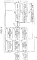
- a hybrid construction machine As shown in Fig. 1 , a hybrid construction machine according to Example 1 has a variable displacement hydraulic pump 1 which discharges hydraulic oil for a not-shown hydraulic actuator, an engine 2 which drives the hydraulic pump 1, an electric motor 3 which is driven by the engine to charge generated electric power into a not-shown electric storage device and which is driven by the electric power charged in the not-shown electric storage device so as to assist the engine 2 to drive the hydraulic pump 1, and a controller 1A which controls driving of the hydraulicpump 1, the engine 2 and the electric motor 3. Further, the hybrid construction machine has an engine control dial (hereinafter abbreviated to "EC dial") 4 operated by an operator, and an operating lever 5.
- EC dial engine control dial
- the controller 1A includes an engine power calculating unit 11 which calculates power generated by the engine 2, a first rotation speed calculating unit 12 which calculates a real rotation speed of the engine to minimize fuel required for generating the engine power, a target maximum total power calculating unit 13 which calculates a target maximum value of total power of the engine 2 and the electric motor 3, a second rotation speed calculating unit 14 which determines a lower limit of a target rotation speed of the engine 2, a target flow rate calculating unit 15 which calculates a target flow rate of the hydraulic oil discharged from the hydraulic pump 1, a third rotation speed calculating unit 16 which calculates a minimum rotation speed of the engine required for securing the target flow rate of the hydraulic pump 1, a target rotation speed calculating unit 17 which selects a largest value from the first rotation speed calculated by the first rotation speed calculating unit 12, the second rotation speed calculated by the second rotation speed calculating unit 14 and the third rotation speed calculated by the third rotation speed calculating unit 16, an engine control unit 18 which controls the engine 3 so as to make the real rotation speed of the engine close to the
- the variable displacement hydraulic pump 1 supplies hydraulic oil to a not-shown hydraulic actuator such as a boom, an arm, a bucket, etc.
- the displacement (amount of hydraulic oil discharged by one turn) of the hydraulic pump 1 can be changed by changing the tilting angle of a swash plate.
- the engine 2 is mechanically connected to the hydraulic pump 1 so that the engine 2 can drive and rotate the hydraulic pump 1.
- the engine 2 consumes fuel stored in a not-shown fuel tank and generates power.
- the power can be changed by changing the amount of fuel injection.
- the electric motor 3 is mechanically connected to the hydraulic pump 1 so that the electric motor 3 can drive and rotate the hydraulic pump 1.
- the electric motor 3 is also mechanically connected to the engine 2.
- the electric motor 3 may consume electric power of a not-shown electric storage device to generate power (motor), and may absorb inertial energy or the power generated in the engine 2 so as to generate (regenerate) power and store the power into the electric storage device.
- the EC dial 4 is designed so that the dial position thereof can be changed by an operator.
- the target rotation speed of the engine 2 is determined based on the dial position of the EC dial 4.
- the target maximum total power of the engine 2 and the electric motor 3 is determined based on the dial position of the EC dial 4. The method for determining the target maximum total power will be described later.
- the operating lever 5 is provided for allowing the operator to operate a hydraulic actuator such as a boom, an arm, a bucket, etc.
- the engine power calculating unit 11 calculates the engine power based on the fuel injection amount and the rotation speed of the engine 2, for example, using a map shown in Fig. 2 .
- the map is set based on the relationship among the fuel injection amount, the rotation speed and the generated power of the engine 2, which relationship is obtained by experiments or the like in advance.
- the first rotation speed calculating unit 12 calculates the first rotation speed which will be described below, based on the engine power calculated by the engine power calculating unit 11, for example, using a map shown in Fig. 3 . That is, in the map, the engine rotation speed to minimize fuel required for generating each power of the engine 2 is set as the first rotation speed based on the relationship between the power and the engine rotation speed, which relationship is obtained by experiments or the like in advance.
- the target maximum total power calculating unit 13 calculates the target maximum total power based on the dial position of the EC dial 4, for example, using a map shown in Fig. 4 .
- a maximum power that can be generated in each dial position of the EC dial 4 by an engine in an ordinal hydraulic excavator that is not hybrid is set as the target maximum total power based on the relationship between the dial position and the maximum power, which relationship is obtained by experiments or the like in advance.
- the "ordinary hydraulic excavator that is not hybrid” means a model whose engine power is substantially equal to the total power of the engine 2 and the electric motor 3 according to the invention.
- the second rotation speed calculating unit 14 calculates the following second rotation speed based on the target maximum total power calculated by the target maximum total power calculating unit 13, for example, using a map shown in Fig. 5 . That is, in the map, each total power of the engine 2 and the electric motor 3 and the minimum engine rotation speed required for generating the power are set as the target maximum total power and the second rotation speed respectively based on the relationship between the total power and the minimum engine rotation speed, which relationship is obtained by experiments or the like in advance.
- the target flow rate calculating unit 15 calculates the target flow rate based on the dial position of the EC dial 4 and the amount of operation on the operating lever 5, for example, using a map shown in Fig. 6 .
- a map shown in Fig. 6 .
- each flow rate of a hydraulic pump in an ordinary hydraulic excavator that is not hybrid is set as the target flow rate based on the relationship among the dial position of the EC dial 4, the amount of operation on the operating lever 5 and the flow rate, which relationship is obtained by experiments or the like in advance.
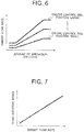
- the third rotation speed calculating unit 16 calculates the following third rotation speed based on the target flow rate calculated by the target flow rate calculating unit 15, for example, using a map shown in Fig. 7 .
- a map shown in Fig. 7 each flow rate of the hydraulic pump 1 and the minimum engine rotation speed required for securing the flow rate are set as the target flow rate and the third rotation speed based on the relationship between the flow rate and the engine rotation speed, which relationship is obtained by experiments or the like in advance.
- the target rotation speed calculating unit 17 selects the largest value from the first rotation speed, the second rotation speed and the third rotation speed.
- the engine control unit 18 controls the fuel injection amount or the fuel injection timing of the engine 2 so as to make the real rotation speed of the engine 2 close to the target rotation speed calculated by the target rotation speed calculating unit 17. For example, the rotation speed, the deviation of the target rotation speed and the integrated value of the deviation are multiplied by gains respectively, and fuel corresponding to a value obtained by the sum of those values is injected.
- the electric motor control unit 19 controls torque generated in the electric motor 3 so as to make the real rotation speed of the engine 2 close to the target rotation speed calculated by the target rotation speed calculating unit 17. For example, the rotation speed, the deviation of the target rotation speed and the integrated value of the deviation are multiplied by gains respectively, and torque corresponding to a value obtained by the sum of those values is generated. Torque generated in the electric motor 3 may be made high when the remaining amount of electric power in the electric storage device is large. Torque generated in the electric motor 3 may be made low or electric power may be generated when the remaining amount of electric power is small.
- the hydraulic pump control unit 20 calculates a target tilting angle of the hydraulic pump 1 using a map so as to change the tilting angle.
- the map is set based on the relationship among the engine rotation speed, the tilting angle and the flow rate, which relationship is obtained by experiments or the like in advance.
- the tilting angle is changed by hydraulic control or electric control.
- an electromagnetic valve is driven to control hydraulic pressure for changing the tilting angle.
- an electric motor an electric motor (another electric motor than the electric motor 3) for changing the tilting angle is driven to change the tilting angle.
- Restriction may be put on the change of the tilting angle by the hydraulic pump control unit 20 so as to prevent the power absorbed by the hydraulic pump 1 from exceeding the target maximum total power calculated by the target maximum total power calculating unit 13.
- restriction may be put on the target flow rate calculated by the target flow rate calculating unit 15 using a value obtained by dividing the target maximum total power by the discharge pressure of the hydraulic pump 1.
- a plurality of hydraulic pumps 1 may be provided. In that case, the same number of target flow rate calculating units 15 and the same number of hydraulic pump control units 20 as the number of hydraulic pumps 1 are provided.
- the third rotation speed calculating unit 16 calculates the third rotation speed based on the highest target flow rate of the target flow rates calculated by the target flow rate calculating units 15.
- Example 8 illustrates an example in which the fuel consumption becomes lower as the rotation speed increases when high power is generated by the engine 2.
- Example 2 of the invention is characterized in that the target rotation speed calculated by the target rotation speed calculating unit 17 is used in the hydraulic pump control unit 20 in place of the real rotation speed of the engine 2. The remaining is the same as that in the hybrid construction machine according to Example 1. Therefore, like parts are referred to by like signs correspondingly, and description thereof will be omitted.
- the target rotation speed changes more quickly than the real rotation speed.
- Example 2 is therefore effective in the case where it takes much time to change the tilting angle of the hydraulic pump 1.
- Example 3 of the invention is characterized in that the flow rate and the discharge pressure of the hydraulic pump 1, the power of the electric motor 3 and the load of accessories such as an air conditioner are used in the engine power calculating unit 11 in place of the fuel injection amount and the rotation speed of the engine 2.
- the engine power calculating unit 11 in Example 3 first multiplies the flow rate and the discharge pressure of the hydraulic pump 1 so as to calculate the power absorbed by the hydraulic pump 1.
- the engine power calculating unit 11 calculates the power generated by the electric motor 3 based on the output of the electric motor control unit 19.
- the engine power calculating unit 11 calculates the power consumed by accessories such as an air conditioner, for example, based on the condition of a switch of the air conditioner.
- the engine power calculating unit 11 sets, as the engine power, a value obtained by subtracting the power generated by the electric motor 3 from the sum of the power absorbed by the hydraulic pump 1 and the power consumed by the accessories. The remaining is the same as that in the hybrid construction machine according to Example 1. Therefore, like parts are referred by like signs correspondingly, and description thereof will be omitted.
- the target flow rate calculated by the target flow rate calculating unit 15 may be used in place of the flow rate of the hydraulic pump 1.
- the target rotation speed calculated by the target rotation speed calculating unit 17 may be used in the hydraulic pump control unit 20 in place of the real rotation speed of the engine 2.
Landscapes
- Engineering & Computer Science (AREA)
- Chemical & Material Sciences (AREA)
- Combustion & Propulsion (AREA)
- General Engineering & Computer Science (AREA)
- Mechanical Engineering (AREA)
- Transportation (AREA)
- Structural Engineering (AREA)
- Civil Engineering (AREA)
- Mining & Mineral Resources (AREA)
- Physics & Mathematics (AREA)
- Automation & Control Theory (AREA)
- General Physics & Mathematics (AREA)
- Software Systems (AREA)
- Theoretical Computer Science (AREA)
- Fluid Mechanics (AREA)
- Computer Vision & Pattern Recognition (AREA)
- Medical Informatics (AREA)
- Evolutionary Computation (AREA)
- Power Engineering (AREA)
- Health & Medical Sciences (AREA)
- Artificial Intelligence (AREA)
- Data Mining & Analysis (AREA)
- Databases & Information Systems (AREA)
- Mathematical Physics (AREA)
- Operation Control Of Excavators (AREA)
- Control Of Vehicle Engines Or Engines For Specific Uses (AREA)
- Electrical Control Of Air Or Fuel Supplied To Internal-Combustion Engine (AREA)
- Combined Controls Of Internal Combustion Engines (AREA)
Claims (8)
- Hybrid-Baumaschine, umfassend: eine variable hydraulische Verdrängerpumpe (1), die Hydrauliköl für ein hydraulisches Betätigungsorgan ausgibt; einen Motor (2), der die Hydraulikpumpe (1) antreibt; einen Elektromotor (3), der von dem Motor (2) angetrieben wird, um erzeugten elektrischen Strom in eine elektrische Speichervorrichtung zu laden, und der von dem elektrischen Strom, der in die elektrische Speichervorrichtung geladen wurde, angetrieben wird, um den Motor zu unterstützen, die hydraulische Pumpe anzutreiben; und eine Steuereinrichtung (18, 19, 20), die das Antreiben der Hydraulikpumpe, des Motors und des Elektromotors steuert; und die eine Motorleistungsberechnungseinheit (11) umfasst, die den von dem Motor (2) erzeugten Strom berechnet, dadurch gekennzeichnet, dass:
die Steuereinrichtung (18, 19, 20) eine erste Drehzahlberechnungseinheit (12) beinhaltet, die eine Drehzahl des Motors (2) berechnet, um Kraftstoff, der für das Erzeugen der Motorleistung benötigt wird, zu minimieren, eine zweite Drehzahlberechnungseinheit (14), die eine Untergrenze einer Zieldrehzahl des Motors (2) bestimmt, eine Zieldrehzahlberechnungseinheit (17), die ein größeres eines einer ersten Drehzahl, die von der ersten Drehzahlberechnungseinheit (12) ausgegeben wird, und einer zweiten Drehzahl, die von der zweiten Drehzahlberechnungseinheit (14) ausgegeben wird, auswählt, eine Motorsteuereinheit (18), die den Motor (2) derart steuert, dass eine reale Drehzahl des Motors (2) nahe an der Zieldrehzahl liegt, eine Zielflussratenberechnungseinheit (15), die eine Zielflussrate des Hydrauliköls, das von der Hydraulikpumpe (1) ausgegeben wird, berechnet, und eine Hydraulikpumpensteuereinheit (20), die die Verdrängung der Hydraulikpumpe (1) auf Basis der Zielflussrate und der realen Drehzahl oder der Zieldrehzahl des Motors (2) steuert. - Hybrid-Baumaschine nach Anspruch 1, dadurch gekennzeichnet, dass:
die Zielflussratenberechnungseinheit (15) die Zielflussrate auf Basis einer Wählposition einer Motorsteuerwählscheibe (4) und eines Betätigungsbetrags an einem Betätigungshebel (5) berechnet. - Hybrid-Baumaschine nach Anspruch 1, dadurch gekennzeichnet, dass:
die Motorleistungsberechnungseinheit (11) die Motorleistung auf Basis eines Betrags der Kraftstoffeinspritzung in den Motor (2) und der Drehzahl des Motors (2) berechnet. - Hybrid-Baumaschine nach Anspruch 1, dadurch gekennzeichnet, dass:
die Motorleistungsberechnungseinheit (11) die Motorleistung auf Basis der Ausgabeflussrate und einem Ausgabedruck der Hydraulikpumpe (1), der Leistung des Elektromotors (3) und einer Last von Zubehör berechnet. - Hybrid-Baumaschine nach Anspruch 1, dadurch gekennzeichnet, dass:eine Ziel-Maximalgesamtleistungs-Berechnungseinheit (13), die einen Ziel-Maximalwert der Gesamtleistung des Motors (2) und des Elektromotors (3) berechnet, bereitgestellt wird; unddie zweite Drehzahlberechnungseinheit (14) eine Mindestdrehzahl des Motors (2) berechnet, die zum Erzeugen der Ziel-Maximalgesamtleistung in dem Motor (2) und dem Elektromotor (3) erforderlich ist.
- Hybrid-Baumaschine nach Anspruch 5, dadurch gekennzeichnet, dass:
die Ziel-Maximalgesamtleistungs-Berechnungseinheit (13) die Ziel-Maximalgesamtleistung auf Basis einer Wählposition einer Motorsteuerwählscheibe (4) berechnet. - Hybrid-Baumaschine nach Anspruch 5, dadurch gekennzeichnet, dass:eine dritte Drehzahlberechnungseinheit (16), die eine Mindestdrehzahl des Motors (2) berechnet, die für Sicherstellung einer Zielflussrate der Hydraulikpumpe (1) erforderlich ist, ferner bereitgestellt wird; unddie Zieldrehzahlberechnungseinheit (17) einen größten Wert aus einer ersten Drehzahl, die von der ersten Drehzahlberechnungseinheit (12) ausgegeben wird, einer zweiten Drehzahl, die von der zweiten Drehzahlberechnungseinheit (14) ausgegeben wird, und einer dritten Drehzahl, die von der dritten Drehzahlberechnungseinheit (16) ausgegeben wird, auswählt.
- Hybrid-Baumaschine nach Anspruch 1, dadurch gekennzeichnet, dass:
die zweite Drehzahlberechnungseinheit (14) eine Mindestdrehzahl des Motors (2) berechnet, die für Sicherstellung einer Zielflussrate der Hydraulikpumpe (1) erforderlich ist.
Applications Claiming Priority (2)
| Application Number | Priority Date | Filing Date | Title |
|---|---|---|---|
| JP2010201102A JP5203434B2 (ja) | 2010-09-08 | 2010-09-08 | ハイブリッド建設機械 |
| PCT/JP2011/068694 WO2012032909A1 (ja) | 2010-09-08 | 2011-08-18 | ハイブリッド建設機械 |
Publications (3)
| Publication Number | Publication Date |
|---|---|
| EP2615212A1 EP2615212A1 (de) | 2013-07-17 |
| EP2615212A4 EP2615212A4 (de) | 2017-11-08 |
| EP2615212B1 true EP2615212B1 (de) | 2019-02-27 |
Family
ID=45810512
Family Applications (1)
| Application Number | Title | Priority Date | Filing Date |
|---|---|---|---|
| EP11823388.1A Not-in-force EP2615212B1 (de) | 2010-09-08 | 2011-08-18 | Hybridbaumaschine mit antriebsmotorsteuerung |
Country Status (6)
| Country | Link |
|---|---|
| US (1) | US8924100B2 (de) |
| EP (1) | EP2615212B1 (de) |
| JP (1) | JP5203434B2 (de) |
| KR (1) | KR101805236B1 (de) |
| CN (1) | CN103080430B (de) |
| WO (1) | WO2012032909A1 (de) |
Families Citing this family (19)
| Publication number | Priority date | Publication date | Assignee | Title |
|---|---|---|---|---|
| US8739906B2 (en) * | 2009-06-19 | 2014-06-03 | Sumitomo Heavy Industries, Ltd. | Hybrid-type construction machine and control method for hybrid-type construction machine |
| KR101112137B1 (ko) * | 2009-07-29 | 2012-02-22 | 볼보 컨스트럭션 이큅먼트 에이비 | 하이브리드식 건설기계의 엔진회전수 변화저감 제어시스템 및 방법 |
| JP5395818B2 (ja) * | 2011-01-21 | 2014-01-22 | 日立建機株式会社 | 作業機械の旋回制御装置 |
| KR101549117B1 (ko) * | 2011-06-27 | 2015-09-01 | 스미도모쥬기가이고교 가부시키가이샤 | 하이브리드식 작업기계 및 그 제어방법 |
| JP5928065B2 (ja) * | 2012-03-27 | 2016-06-01 | コベルコ建機株式会社 | 制御装置及びこれを備えた建設機械 |
| JP5828808B2 (ja) * | 2012-06-29 | 2015-12-09 | 日立建機株式会社 | 油圧作業機械 |
| CN102828834B (zh) * | 2012-08-16 | 2015-05-13 | 三一重机有限公司 | 发动机功率控制方法、发动机功率控制器和控制系统 |
| KR102054520B1 (ko) | 2013-03-21 | 2020-01-22 | 두산인프라코어 주식회사 | 건설기계 유압시스템의 제어방법 |
| US9772018B2 (en) * | 2013-03-27 | 2017-09-26 | Kubota Corporation | Working machine |
| JP6077365B2 (ja) * | 2013-04-01 | 2017-02-08 | 株式会社神戸製鋼所 | エンジン制御装置及びこれを備えたハイブリッド建設機械 |
| JP6159681B2 (ja) * | 2014-05-07 | 2017-07-05 | 日立建機株式会社 | ハイブリッド作業機械 |
| JP6502742B2 (ja) * | 2015-05-11 | 2019-04-17 | 川崎重工業株式会社 | 建設機械の油圧駆動システム |
| EP4123094A1 (de) | 2018-09-10 | 2023-01-25 | Artemis Intelligent Power Limited | Arbeitsmaschine mit hydraulik pumpe/motor steuerung |
| EP3620582B1 (de) | 2018-09-10 | 2022-03-09 | Artemis Intelligent Power Limited | Vorrichtung umfassend einen hydraulikkreis |
| US11454003B2 (en) | 2018-09-10 | 2022-09-27 | Artemis Intelligent Power Limited | Apparatus with hydraulic machine controller |
| CA3151727C (en) | 2019-09-24 | 2025-05-06 | Doosan Bobcat North America, Inc. | CYCLE TIME MANAGEMENT SYSTEM AND PROCESSES |
| CN110725360A (zh) * | 2019-12-03 | 2020-01-24 | 湖南力诚新能源科技有限公司 | 一种电动挖掘机液压泵控制装置及液压泵的控制方法 |
| CN113027624B (zh) * | 2021-03-31 | 2023-03-28 | 潍柴动力股份有限公司 | 一种发动机碳烟控制方法及装置 |
| CN115324149B (zh) * | 2022-06-30 | 2023-10-27 | 三一重机有限公司 | 液压泵控制方法、装置及作业机械 |
Family Cites Families (25)
| Publication number | Priority date | Publication date | Assignee | Title |
|---|---|---|---|---|
| JP3587957B2 (ja) * | 1997-06-12 | 2004-11-10 | 日立建機株式会社 | 建設機械のエンジン制御装置 |
| JP4512283B2 (ja) * | 2001-03-12 | 2010-07-28 | 株式会社小松製作所 | ハイブリッド式建設機械 |
| JP4800514B2 (ja) * | 2001-07-18 | 2011-10-26 | 日立建機株式会社 | ハイブリッド建設機械の駆動制御装置、ハイブリッド建設機械及びその駆動制御プログラム |
| JP2004011168A (ja) * | 2002-06-04 | 2004-01-15 | Komatsu Ltd | 建設機械 |
| JP4082935B2 (ja) * | 2002-06-05 | 2008-04-30 | 株式会社小松製作所 | ハイブリッド式建設機械 |
| JP4017073B2 (ja) * | 2002-10-29 | 2007-12-05 | 株式会社小松製作所 | 作業機械のエンジン回転数制御装置 |
| US7058495B2 (en) * | 2003-09-04 | 2006-06-06 | Caterpillar Inc. | Work implement control system and method |
| JP4171467B2 (ja) * | 2005-01-20 | 2008-10-22 | 株式会社小松製作所 | 建設機械の制御モード切換装置および建設機械 |
| JP2006273514A (ja) * | 2005-03-29 | 2006-10-12 | Toyota Industries Corp | ハイブリッド型フォークリフト |
| US8424302B2 (en) * | 2005-10-28 | 2013-04-23 | Komatsu Ltd. | Control device of engine, control device of engine and hydraulic pump, and control device of engine, hydraulic pump, and generator motor |
| US8087240B2 (en) * | 2005-10-31 | 2012-01-03 | Komatsu Ltd. | Control apparatus for work machine |
| JP4725406B2 (ja) * | 2006-04-26 | 2011-07-13 | コベルコ建機株式会社 | ハイブリッド式作業機械の動力源装置 |
| JP5055948B2 (ja) * | 2006-10-20 | 2012-10-24 | コベルコ建機株式会社 | ハイブリッド作業機械 |
| DE112008000818B4 (de) * | 2007-03-28 | 2017-12-14 | Komatsu Ltd. | Verfahren zur Steuerung einer Hybridbaumaschine und Hybridbaumaschine |
| US8607558B2 (en) * | 2007-03-29 | 2013-12-17 | Komatsu Ltd. | Work machine |
| KR101391104B1 (ko) * | 2007-03-29 | 2014-04-30 | 가부시키가이샤 고마쓰 세이사쿠쇼 | 건설 기계 및 건설 기계의 제어 방법 |
| JP4922881B2 (ja) * | 2007-09-19 | 2012-04-25 | 株式会社小松製作所 | エンジンの制御装置 |
| JP5156312B2 (ja) * | 2007-09-19 | 2013-03-06 | 株式会社小松製作所 | エンジンの制御装置 |
| JP5166806B2 (ja) * | 2007-09-19 | 2013-03-21 | 株式会社小松製作所 | エンジンの制御装置 |
| JP5226734B2 (ja) * | 2010-05-20 | 2013-07-03 | 株式会社小松製作所 | ハイブリッド建設機械 |
| JP5427110B2 (ja) * | 2010-05-25 | 2014-02-26 | 川崎重工業株式会社 | 建設機械及びその制御方法 |
| JP5665874B2 (ja) * | 2010-10-06 | 2015-02-04 | 住友重機械工業株式会社 | ハイブリッド型作業機械及びその制御方法 |
| JP5356436B2 (ja) * | 2011-03-01 | 2013-12-04 | 日立建機株式会社 | 建設機械の制御装置 |
| JP5836362B2 (ja) * | 2011-03-08 | 2015-12-24 | 住友建機株式会社 | ショベル及びショベルの制御方法 |
| JP5653844B2 (ja) * | 2011-06-07 | 2015-01-14 | 住友建機株式会社 | ショベル |
-
2010
- 2010-09-08 JP JP2010201102A patent/JP5203434B2/ja not_active Expired - Fee Related
-
2011
- 2011-08-18 EP EP11823388.1A patent/EP2615212B1/de not_active Not-in-force
- 2011-08-18 WO PCT/JP2011/068694 patent/WO2012032909A1/ja not_active Ceased
- 2011-08-18 KR KR1020137004007A patent/KR101805236B1/ko not_active Expired - Fee Related
- 2011-08-18 US US13/817,913 patent/US8924100B2/en active Active
- 2011-08-18 CN CN201180040316.8A patent/CN103080430B/zh not_active Expired - Fee Related
Non-Patent Citations (1)
| Title |
|---|
| None * |
Also Published As
| Publication number | Publication date |
|---|---|
| CN103080430B (zh) | 2015-03-25 |
| US8924100B2 (en) | 2014-12-30 |
| KR101805236B1 (ko) | 2017-12-06 |
| JP5203434B2 (ja) | 2013-06-05 |
| WO2012032909A1 (ja) | 2012-03-15 |
| EP2615212A4 (de) | 2017-11-08 |
| EP2615212A1 (de) | 2013-07-17 |
| US20130197768A1 (en) | 2013-08-01 |
| CN103080430A (zh) | 2013-05-01 |
| JP2012057347A (ja) | 2012-03-22 |
| KR20130114081A (ko) | 2013-10-16 |
Similar Documents
| Publication | Publication Date | Title |
|---|---|---|
| EP2615212B1 (de) | Hybridbaumaschine mit antriebsmotorsteuerung | |
| KR101112137B1 (ko) | 하이브리드식 건설기계의 엔진회전수 변화저감 제어시스템 및 방법 | |
| US8439139B2 (en) | Method of controlling hybrid construction machine and hybrid construction machine | |
| CN104159803B (zh) | 工程机械的控制装置 | |
| US9347389B2 (en) | Engine control device of work machine and engine control method therefor | |
| US10315508B2 (en) | Hybrid work machine | |
| EP2705967B1 (de) | Hybride Baumaschine | |
| EP2770119B1 (de) | Hydraulische arbeitsmaschine mit hybridantrieb | |
| KR101714948B1 (ko) | 건설 기계 | |
| KR101908554B1 (ko) | 쇼벨 및 쇼벨의 제어 방법 | |
| US20160340871A1 (en) | Engine and Pump Control Device and Working Machine | |
| JP2007290607A (ja) | ハイブリッド式作業機械の動力源装置 | |
| JP2010173599A (ja) | ハイブリッド式作業機械の制御方法、及びサーボ制御システムの制御方法 | |
| EP2677147B1 (de) | Leistungsquellenvorrichtung und hybridbaumaschine damit | |
| KR20130114871A (ko) | 굴삭기 전기 동력시스템 | |
| JP4173489B2 (ja) | ハイブリッド駆動式のホイール系作業車両 | |
| KR100837905B1 (ko) | 하이브리드 연료전지 차량의 동력 분배 제어방법 |
Legal Events
| Date | Code | Title | Description |
|---|---|---|---|
| PUAI | Public reference made under article 153(3) epc to a published international application that has entered the european phase |
Free format text: ORIGINAL CODE: 0009012 |
|
| 17P | Request for examination filed |
Effective date: 20130408 |
|
| AK | Designated contracting states |
Kind code of ref document: A1 Designated state(s): AL AT BE BG CH CY CZ DE DK EE ES FI FR GB GR HR HU IE IS IT LI LT LU LV MC MK MT NL NO PL PT RO RS SE SI SK SM TR |
|
| DAX | Request for extension of the european patent (deleted) | ||
| RIC1 | Information provided on ipc code assigned before grant |
Ipc: B60W 10/08 20060101ALI20170602BHEP Ipc: F02D 29/04 20060101ALI20170602BHEP Ipc: F02D 41/02 20060101ALI20170602BHEP Ipc: B60W 10/30 20060101ALI20170602BHEP Ipc: F02D 29/00 20060101ALI20170602BHEP Ipc: E02F 9/20 20060101AFI20170602BHEP Ipc: F02D 31/00 20060101ALI20170602BHEP Ipc: B60W 10/06 20060101ALI20170602BHEP Ipc: B60W 20/00 20160101ALI20170602BHEP Ipc: F02D 45/00 20060101ALI20170602BHEP Ipc: G06F 17/00 20060101ALI20170602BHEP Ipc: G05B 13/02 20060101ALI20170602BHEP Ipc: B60W 10/103 20120101ALI20170602BHEP Ipc: E02F 9/22 20060101ALI20170602BHEP |
|
| RA4 | Supplementary search report drawn up and despatched (corrected) |
Effective date: 20171006 |
|
| RIC1 | Information provided on ipc code assigned before grant |
Ipc: E02F 9/20 20060101AFI20170929BHEP Ipc: F02D 45/00 20060101ALI20170929BHEP Ipc: E02F 9/22 20060101ALI20170929BHEP Ipc: F02D 31/00 20060101ALI20170929BHEP Ipc: B60W 10/30 20060101ALI20170929BHEP Ipc: G06F 17/00 20060101ALI20170929BHEP Ipc: B60W 10/103 20120101ALI20170929BHEP Ipc: F02D 29/04 20060101ALI20170929BHEP Ipc: B60W 10/08 20060101ALI20170929BHEP Ipc: F02D 41/02 20060101ALI20170929BHEP Ipc: F02D 29/00 20060101ALI20170929BHEP Ipc: G05B 13/02 20060101ALI20170929BHEP Ipc: B60W 20/00 20160101ALI20170929BHEP Ipc: B60W 10/06 20060101ALI20170929BHEP |
|
| GRAP | Despatch of communication of intention to grant a patent |
Free format text: ORIGINAL CODE: EPIDOSNIGR1 |
|
| STAA | Information on the status of an ep patent application or granted ep patent |
Free format text: STATUS: GRANT OF PATENT IS INTENDED |
|
| INTG | Intention to grant announced |
Effective date: 20181025 |
|
| GRAS | Grant fee paid |
Free format text: ORIGINAL CODE: EPIDOSNIGR3 |
|
| GRAA | (expected) grant |
Free format text: ORIGINAL CODE: 0009210 |
|
| STAA | Information on the status of an ep patent application or granted ep patent |
Free format text: STATUS: THE PATENT HAS BEEN GRANTED |
|
| RAP1 | Party data changed (applicant data changed or rights of an application transferred) |
Owner name: HITACHI CONSTRUCTION MACHINERY CO., LTD. |
|
| AK | Designated contracting states |
Kind code of ref document: B1 Designated state(s): AL AT BE BG CH CY CZ DE DK EE ES FI FR GB GR HR HU IE IS IT LI LT LU LV MC MK MT NL NO PL PT RO RS SE SI SK SM TR |
|
| REG | Reference to a national code |
Ref country code: GB Ref legal event code: FG4D |
|
| REG | Reference to a national code |
Ref country code: CH Ref legal event code: EP |
|
| REG | Reference to a national code |
Ref country code: AT Ref legal event code: REF Ref document number: 1101528 Country of ref document: AT Kind code of ref document: T Effective date: 20190315 |
|
| REG | Reference to a national code |
Ref country code: IE Ref legal event code: FG4D |
|
| REG | Reference to a national code |
Ref country code: DE Ref legal event code: R096 Ref document number: 602011056705 Country of ref document: DE |
|
| REG | Reference to a national code |
Ref country code: NL Ref legal event code: MP Effective date: 20190227 |
|
| REG | Reference to a national code |
Ref country code: LT Ref legal event code: MG4D |
|
| PG25 | Lapsed in a contracting state [announced via postgrant information from national office to epo] |
Ref country code: SE Free format text: LAPSE BECAUSE OF FAILURE TO SUBMIT A TRANSLATION OF THE DESCRIPTION OR TO PAY THE FEE WITHIN THE PRESCRIBED TIME-LIMIT Effective date: 20190227 Ref country code: NL Free format text: LAPSE BECAUSE OF FAILURE TO SUBMIT A TRANSLATION OF THE DESCRIPTION OR TO PAY THE FEE WITHIN THE PRESCRIBED TIME-LIMIT Effective date: 20190227 Ref country code: PT Free format text: LAPSE BECAUSE OF FAILURE TO SUBMIT A TRANSLATION OF THE DESCRIPTION OR TO PAY THE FEE WITHIN THE PRESCRIBED TIME-LIMIT Effective date: 20190627 Ref country code: LT Free format text: LAPSE BECAUSE OF FAILURE TO SUBMIT A TRANSLATION OF THE DESCRIPTION OR TO PAY THE FEE WITHIN THE PRESCRIBED TIME-LIMIT Effective date: 20190227 Ref country code: NO Free format text: LAPSE BECAUSE OF FAILURE TO SUBMIT A TRANSLATION OF THE DESCRIPTION OR TO PAY THE FEE WITHIN THE PRESCRIBED TIME-LIMIT Effective date: 20190527 Ref country code: FI Free format text: LAPSE BECAUSE OF FAILURE TO SUBMIT A TRANSLATION OF THE DESCRIPTION OR TO PAY THE FEE WITHIN THE PRESCRIBED TIME-LIMIT Effective date: 20190227 |
|
| PG25 | Lapsed in a contracting state [announced via postgrant information from national office to epo] |
Ref country code: IS Free format text: LAPSE BECAUSE OF FAILURE TO SUBMIT A TRANSLATION OF THE DESCRIPTION OR TO PAY THE FEE WITHIN THE PRESCRIBED TIME-LIMIT Effective date: 20190627 Ref country code: RS Free format text: LAPSE BECAUSE OF FAILURE TO SUBMIT A TRANSLATION OF THE DESCRIPTION OR TO PAY THE FEE WITHIN THE PRESCRIBED TIME-LIMIT Effective date: 20190227 Ref country code: BG Free format text: LAPSE BECAUSE OF FAILURE TO SUBMIT A TRANSLATION OF THE DESCRIPTION OR TO PAY THE FEE WITHIN THE PRESCRIBED TIME-LIMIT Effective date: 20190527 Ref country code: HR Free format text: LAPSE BECAUSE OF FAILURE TO SUBMIT A TRANSLATION OF THE DESCRIPTION OR TO PAY THE FEE WITHIN THE PRESCRIBED TIME-LIMIT Effective date: 20190227 Ref country code: LV Free format text: LAPSE BECAUSE OF FAILURE TO SUBMIT A TRANSLATION OF THE DESCRIPTION OR TO PAY THE FEE WITHIN THE PRESCRIBED TIME-LIMIT Effective date: 20190227 Ref country code: GR Free format text: LAPSE BECAUSE OF FAILURE TO SUBMIT A TRANSLATION OF THE DESCRIPTION OR TO PAY THE FEE WITHIN THE PRESCRIBED TIME-LIMIT Effective date: 20190528 |
|
| REG | Reference to a national code |
Ref country code: AT Ref legal event code: MK05 Ref document number: 1101528 Country of ref document: AT Kind code of ref document: T Effective date: 20190227 |
|
| PG25 | Lapsed in a contracting state [announced via postgrant information from national office to epo] |
Ref country code: CZ Free format text: LAPSE BECAUSE OF FAILURE TO SUBMIT A TRANSLATION OF THE DESCRIPTION OR TO PAY THE FEE WITHIN THE PRESCRIBED TIME-LIMIT Effective date: 20190227 Ref country code: ES Free format text: LAPSE BECAUSE OF FAILURE TO SUBMIT A TRANSLATION OF THE DESCRIPTION OR TO PAY THE FEE WITHIN THE PRESCRIBED TIME-LIMIT Effective date: 20190227 Ref country code: SK Free format text: LAPSE BECAUSE OF FAILURE TO SUBMIT A TRANSLATION OF THE DESCRIPTION OR TO PAY THE FEE WITHIN THE PRESCRIBED TIME-LIMIT Effective date: 20190227 Ref country code: AL Free format text: LAPSE BECAUSE OF FAILURE TO SUBMIT A TRANSLATION OF THE DESCRIPTION OR TO PAY THE FEE WITHIN THE PRESCRIBED TIME-LIMIT Effective date: 20190227 Ref country code: EE Free format text: LAPSE BECAUSE OF FAILURE TO SUBMIT A TRANSLATION OF THE DESCRIPTION OR TO PAY THE FEE WITHIN THE PRESCRIBED TIME-LIMIT Effective date: 20190227 Ref country code: DK Free format text: LAPSE BECAUSE OF FAILURE TO SUBMIT A TRANSLATION OF THE DESCRIPTION OR TO PAY THE FEE WITHIN THE PRESCRIBED TIME-LIMIT Effective date: 20190227 Ref country code: RO Free format text: LAPSE BECAUSE OF FAILURE TO SUBMIT A TRANSLATION OF THE DESCRIPTION OR TO PAY THE FEE WITHIN THE PRESCRIBED TIME-LIMIT Effective date: 20190227 Ref country code: IT Free format text: LAPSE BECAUSE OF FAILURE TO SUBMIT A TRANSLATION OF THE DESCRIPTION OR TO PAY THE FEE WITHIN THE PRESCRIBED TIME-LIMIT Effective date: 20190227 |
|
| REG | Reference to a national code |
Ref country code: DE Ref legal event code: R097 Ref document number: 602011056705 Country of ref document: DE |
|
| PG25 | Lapsed in a contracting state [announced via postgrant information from national office to epo] |
Ref country code: SM Free format text: LAPSE BECAUSE OF FAILURE TO SUBMIT A TRANSLATION OF THE DESCRIPTION OR TO PAY THE FEE WITHIN THE PRESCRIBED TIME-LIMIT Effective date: 20190227 Ref country code: PL Free format text: LAPSE BECAUSE OF FAILURE TO SUBMIT A TRANSLATION OF THE DESCRIPTION OR TO PAY THE FEE WITHIN THE PRESCRIBED TIME-LIMIT Effective date: 20190227 |
|
| PG25 | Lapsed in a contracting state [announced via postgrant information from national office to epo] |
Ref country code: AT Free format text: LAPSE BECAUSE OF FAILURE TO SUBMIT A TRANSLATION OF THE DESCRIPTION OR TO PAY THE FEE WITHIN THE PRESCRIBED TIME-LIMIT Effective date: 20190227 |
|
| PLBE | No opposition filed within time limit |
Free format text: ORIGINAL CODE: 0009261 |
|
| STAA | Information on the status of an ep patent application or granted ep patent |
Free format text: STATUS: NO OPPOSITION FILED WITHIN TIME LIMIT |
|
| 26N | No opposition filed |
Effective date: 20191128 |
|
| PG25 | Lapsed in a contracting state [announced via postgrant information from national office to epo] |
Ref country code: SI Free format text: LAPSE BECAUSE OF FAILURE TO SUBMIT A TRANSLATION OF THE DESCRIPTION OR TO PAY THE FEE WITHIN THE PRESCRIBED TIME-LIMIT Effective date: 20190227 |
|
| PG25 | Lapsed in a contracting state [announced via postgrant information from national office to epo] |
Ref country code: TR Free format text: LAPSE BECAUSE OF FAILURE TO SUBMIT A TRANSLATION OF THE DESCRIPTION OR TO PAY THE FEE WITHIN THE PRESCRIBED TIME-LIMIT Effective date: 20190227 |
|
| PG25 | Lapsed in a contracting state [announced via postgrant information from national office to epo] |
Ref country code: LU Free format text: LAPSE BECAUSE OF NON-PAYMENT OF DUE FEES Effective date: 20190818 Ref country code: LI Free format text: LAPSE BECAUSE OF NON-PAYMENT OF DUE FEES Effective date: 20190831 Ref country code: CH Free format text: LAPSE BECAUSE OF NON-PAYMENT OF DUE FEES Effective date: 20190831 Ref country code: MC Free format text: LAPSE BECAUSE OF FAILURE TO SUBMIT A TRANSLATION OF THE DESCRIPTION OR TO PAY THE FEE WITHIN THE PRESCRIBED TIME-LIMIT Effective date: 20190227 |
|
| REG | Reference to a national code |
Ref country code: BE Ref legal event code: MM Effective date: 20190831 |
|
| PG25 | Lapsed in a contracting state [announced via postgrant information from national office to epo] |
Ref country code: IE Free format text: LAPSE BECAUSE OF NON-PAYMENT OF DUE FEES Effective date: 20190818 Ref country code: FR Free format text: LAPSE BECAUSE OF NON-PAYMENT OF DUE FEES Effective date: 20190831 |
|
| PG25 | Lapsed in a contracting state [announced via postgrant information from national office to epo] |
Ref country code: BE Free format text: LAPSE BECAUSE OF NON-PAYMENT OF DUE FEES Effective date: 20190831 |
|
| PG25 | Lapsed in a contracting state [announced via postgrant information from national office to epo] |
Ref country code: CY Free format text: LAPSE BECAUSE OF FAILURE TO SUBMIT A TRANSLATION OF THE DESCRIPTION OR TO PAY THE FEE WITHIN THE PRESCRIBED TIME-LIMIT Effective date: 20190227 |
|
| PG25 | Lapsed in a contracting state [announced via postgrant information from national office to epo] |
Ref country code: MT Free format text: LAPSE BECAUSE OF FAILURE TO SUBMIT A TRANSLATION OF THE DESCRIPTION OR TO PAY THE FEE WITHIN THE PRESCRIBED TIME-LIMIT Effective date: 20190227 Ref country code: HU Free format text: LAPSE BECAUSE OF FAILURE TO SUBMIT A TRANSLATION OF THE DESCRIPTION OR TO PAY THE FEE WITHIN THE PRESCRIBED TIME-LIMIT; INVALID AB INITIO Effective date: 20110818 |
|
| PGFP | Annual fee paid to national office [announced via postgrant information from national office to epo] |
Ref country code: GB Payment date: 20210707 Year of fee payment: 11 Ref country code: DE Payment date: 20210706 Year of fee payment: 11 |
|
| PG25 | Lapsed in a contracting state [announced via postgrant information from national office to epo] |
Ref country code: MK Free format text: LAPSE BECAUSE OF FAILURE TO SUBMIT A TRANSLATION OF THE DESCRIPTION OR TO PAY THE FEE WITHIN THE PRESCRIBED TIME-LIMIT Effective date: 20190227 |
|
| REG | Reference to a national code |
Ref country code: DE Ref legal event code: R119 Ref document number: 602011056705 Country of ref document: DE |
|
| GBPC | Gb: european patent ceased through non-payment of renewal fee |
Effective date: 20220818 |
|
| PG25 | Lapsed in a contracting state [announced via postgrant information from national office to epo] |
Ref country code: DE Free format text: LAPSE BECAUSE OF NON-PAYMENT OF DUE FEES Effective date: 20230301 |
|
| PG25 | Lapsed in a contracting state [announced via postgrant information from national office to epo] |
Ref country code: GB Free format text: LAPSE BECAUSE OF NON-PAYMENT OF DUE FEES Effective date: 20220818 |