EP2615015A2 - Fahrradleuchte - Google Patents
Fahrradleuchte Download PDFInfo
- Publication number
- EP2615015A2 EP2615015A2 EP12199297.8A EP12199297A EP2615015A2 EP 2615015 A2 EP2615015 A2 EP 2615015A2 EP 12199297 A EP12199297 A EP 12199297A EP 2615015 A2 EP2615015 A2 EP 2615015A2
- Authority
- EP
- European Patent Office
- Prior art keywords
- lamp
- illumination
- type
- action
- user action
- Prior art date
- Legal status (The legal status is an assumption and is not a legal conclusion. Google has not performed a legal analysis and makes no representation as to the accuracy of the status listed.)
- Withdrawn
Links
Images


Classifications
-
- H—ELECTRICITY
- H05—ELECTRIC TECHNIQUES NOT OTHERWISE PROVIDED FOR
- H05B—ELECTRIC HEATING; ELECTRIC LIGHT SOURCES NOT OTHERWISE PROVIDED FOR; CIRCUIT ARRANGEMENTS FOR ELECTRIC LIGHT SOURCES, IN GENERAL
- H05B45/00—Circuit arrangements for operating light-emitting diodes [LED]
- H05B45/10—Controlling the intensity of the light
-
- F—MECHANICAL ENGINEERING; LIGHTING; HEATING; WEAPONS; BLASTING
- F21—LIGHTING
- F21L—LIGHTING DEVICES OR SYSTEMS THEREOF, BEING PORTABLE OR SPECIALLY ADAPTED FOR TRANSPORTATION
- F21L4/00—Electric lighting devices with self-contained electric batteries or cells
- F21L4/02—Electric lighting devices with self-contained electric batteries or cells characterised by the provision of two or more light sources
-
- B—PERFORMING OPERATIONS; TRANSPORTING
- B62—LAND VEHICLES FOR TRAVELLING OTHERWISE THAN ON RAILS
- B62J—CYCLE SADDLES OR SEATS; AUXILIARY DEVICES OR ACCESSORIES SPECIALLY ADAPTED TO CYCLES AND NOT OTHERWISE PROVIDED FOR, e.g. ARTICLE CARRIERS OR CYCLE PROTECTORS
- B62J6/00—Arrangement of optical signalling or lighting devices on cycles; Mounting or supporting thereof; Circuits therefor
- B62J6/02—Headlights
- B62J6/028—Headlights specially adapted for rider-propelled cycles with or without additional source of power
- B62J6/029—Headlights specially adapted for rider-propelled cycles with or without additional source of power characterised by the structure, e.g. casings
-
- B—PERFORMING OPERATIONS; TRANSPORTING
- B62—LAND VEHICLES FOR TRAVELLING OTHERWISE THAN ON RAILS
- B62J—CYCLE SADDLES OR SEATS; AUXILIARY DEVICES OR ACCESSORIES SPECIALLY ADAPTED TO CYCLES AND NOT OTHERWISE PROVIDED FOR, e.g. ARTICLE CARRIERS OR CYCLE PROTECTORS
- B62J6/00—Arrangement of optical signalling or lighting devices on cycles; Mounting or supporting thereof; Circuits therefor
- B62J6/16—Arrangement of switches
-
- F—MECHANICAL ENGINEERING; LIGHTING; HEATING; WEAPONS; BLASTING
- F21—LIGHTING
- F21L—LIGHTING DEVICES OR SYSTEMS THEREOF, BEING PORTABLE OR SPECIALLY ADAPTED FOR TRANSPORTATION
- F21L4/00—Electric lighting devices with self-contained electric batteries or cells
-
- F—MECHANICAL ENGINEERING; LIGHTING; HEATING; WEAPONS; BLASTING
- F21—LIGHTING
- F21V—FUNCTIONAL FEATURES OR DETAILS OF LIGHTING DEVICES OR SYSTEMS THEREOF; STRUCTURAL COMBINATIONS OF LIGHTING DEVICES WITH OTHER ARTICLES, NOT OTHERWISE PROVIDED FOR
- F21V23/00—Arrangement of electric circuit elements in or on lighting devices
- F21V23/04—Arrangement of electric circuit elements in or on lighting devices the elements being switches
- F21V23/0442—Arrangement of electric circuit elements in or on lighting devices the elements being switches activated by means of a sensor, e.g. motion or photodetectors
- F21V23/0492—Arrangement of electric circuit elements in or on lighting devices the elements being switches activated by means of a sensor, e.g. motion or photodetectors the sensor detecting a change in orientation, a movement or an acceleration of the lighting device, e.g. a tilt switch
Definitions
- the present invention relates to a lamp and in particular a battery-powered, LED (light emitting diode) lamp.
- the means for detecting a sequence of motions is an accelerometer and the lights are LEDs alternatively illuminated in accordance with the movement detected by the accelerometer.
- the lamp as marketed has a button that must be depressed in with indicia for the required mode upper most.
- the mode is then initiated. After initiation, selections within the mode, for instance flash on and off can be selected by turning about the barrel with out the button depressed.
- the object of the present invention is to provide an improved LED lamp adapted to be controlled entirely by movements imparted to it.
- a bicycle lamp comprising:
- the circuitry is further adapted to switch between successive brightnesses of illumination by repetition of the second type of user action, with increase of brightness following this action in one sense and decrease in brightness following this action in the opposite sense.
- this action will be movement in an arc, clockwise being the one sense and anti-clockwise being the other sense.
- Alternatives are inversion one way or the other and swinging one way or the other.
- a further action in the decrease sense when the lamp is in low or lowest brightness to switch the lamp OFF, bypassing the active state.
- this action needs to be taken with the lamp in a predetermined orientation to avoid switching from high illumination to OFF without stopping at intentional low illumination.
- modes of illumination beyond mere changes in brightness they can be selected by further action of a third type.
- they are selected by further actions of the one type and indeed the same number of such actions, although differing numbers may be used.
- These modes can be selected sequentially, but again in the preferred embodiments they are selected by their application, with the lamp in differing orientations.
- the one type of user action involves faster changes of position and/or orientation or differentials thereof i.e. accelerations, than those of the other type.
- the one type of action involves a plurality of sharp taps against the lamp, involving relatively high accelerations, with little overall change of position, and correspondingly high signals from the sensor such as to be able to be detected by the circuitry which is quiescent; whereas the second type of action involves gentler circular movements involving lower accelerations and lower signals able to be detected by the circuitry in active state.
- the circuitry is adapted maintain the status display LED array ON in the illumination state.
- the status display LED array includes a first array of LEDs to indicate battery status and a second array of LEDs to indicate illumination brightness.
- the inertial sensor will normally be a capacitive Micro-Electro-Mechanical Systems (MEMS) accelerometer, adapted to detect movement of the sensor by virtue of the displacement of a seismic mass between two charged plates causing a change in the capacitance between the two plates.
- MEMS Micro-Electro-Mechanical Systems
- the accelerometer can detect movement of the lamp and the housing in terms of acceleration of the mass and orientation in terms of the gravitational attraction on the mass.
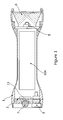
- a lamp has a body 1, in which is mounted a printed circuit board (PCB) 2, to which is connected amongst other components a charging port 3.
- a battery 4 is housed in the body, which also carries a light emitting diode 5 and a reflector 6 at the end opposite from the port 3. Adjacent the port is a press button switch 7.
- Figure 1 is diagrammatic, insofar for instance as wiring is not shown.
- IC integrated circuit
- the port 3, the battery 4, the LED 5 and the switch 7 are connected to the circuit.
- the switch incorporates a bi-colour LED 14 powered by the IC 12 to indicate battery state and the state of powering of the lamp.
- the switch itself is connected to ground an input terminal 15 of the IC for controlling it.
- the LED is switched on by applying a voltage to the base of a switching field effect transistor 16 in series with its earth connection.
- Brightness of the LED is controlled by pulse width modulation, that is controlling proportion of the time that it is switched on, that is the proportion of the time that current is actually flowing through it.
- the IC is provided with a battery voltage measuring circuit 17 and is programmed to adjust the pulse width of current supply for desired brightness.
- the actual current is measured in terms of voltage across a resistor 18 in series with the transistor 16, the voltage being measured by an amplifier circuit 19 and fed back to the IC 12 for control of the pulse width.
- a temperature measuring circuit 20 is provided to reduce the current in the event of LED resistance drop to avoid thermal run away.
- the IC 12 can be programmed to reduce the brightness in event that the temperature rises unacceptably.
- the battery is connected between a positive voltage line 21 and local earth 22 in the lamp.
- the central contact 23 of the port 24 is connected to the voltage line 21, i. e. to the positive battery terminal, but the outer contact 25 is not connected directly to earth. This is to protect the battery from accidental short-circuiting.
- a field effect transistor switch 26 is provided, associated with a detection circuit 27. Normally the outer contact will be grounded via a high resistance (100k) 28.
- the IC 12 can be controlled by operation of the switch to apply a voltage on line 30 switch on the transistor 26.
- the load can be powered at full battery voltage.
- a fuse 31 is provided to protect against excessive current drain.
- the battery is a Lithium Ion battery it will be provided with its own internal battery protection circuit.
- the lamp can have the following switch actuation protocol:
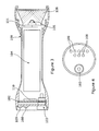
- a lamp 100 of the present invention is similar to that of Our Earlier Application in having a printed circuit board (PCB) 102 and a battery 104 mounted in the body.
- An LED 105, mounted on an emitter plate 101, and a reflector 106 are housed on the body at an opposite end to a charging port 103.
- Adjacent to the port 103, an array of three illumination status blue LEDS 108 and an array of five battery-status red LEDs 109 are provided.
- prior press button switch 7 is omitted.
- the components 103 - 109 are connected to a power management circuit 110 which is mounted on the PCB 102.
- the power management circuit is similar to the prior circuit 11 although it has a different integrated circuit (IC) 111 to that of IC 12, of the PIC18F14K22-I/ML type.
- the positive terminal of the battery 104 is connected to positive voltage line 112 and the negative terminal to local earth 113. Again the central contact 114 of port 103 is connected to the positive voltage line 112 and the outer contact 115 is not connected directly to earth.
- a field effect transistor switch 116 is provided to allow the battery to be charged, however the prior detection circuit 27 is omitted since the charging port is not required for the supply of electrical current from the battery for external use.
- the actual current is again measured in terms of voltage across resistors 118 and 119 via transistor 120, however the prior amplifier circuit 19 is omitted and the signal is fed back to the IC 111 where the voltage is measured by a voltage measuring circuit within the IC 111 for control of pulse width.
- a circuit board temperature measuring circuit 121 similar to prior circuit 17, is also provided.
- the PCB 102 includes a capacitive Micro-Electro-Mechanical Systems (MEMS) accelerometer 123 of the type having a seismic mass, such that it can detect acceleration of the printed circuit on which it is mounted, i.e. acceleration of the lamp as well as the orientation of the lamp by virtue of the action of the gravity on the seismic mass.
- MEMS Micro-Electro-Mechanical Systems
- a voltage regulator 124 between the accelerometer 123 and the positive voltage line 112 limits the maximum voltage which can be applied to the accelerometer.
- Measurement signals from the accelerometer are also fed into the IC 111 which is programmed to respond to specific signal patterns generated by specific user actions on the lamp as described below.
- the lamp In the quiescent state of the circuit, corresponding to that of the lamp of Our Earlier Application which is switched from quiescent to illumination state by pressing the button switch 7, the lamp is subjected to a first type of user action, in that it is tapped laterally of its body five times. Tapping without significant overall movement generates sufficiently high signals from the accelerometer for them to be recognised even although the circuit is in quiescent state. This switches the circuitry on to the extent that the battery status LEDs 109 are switched ON to indicate the state of charge of the battery. Five taps are used to ensure that the lamp does not switch to this active status unintentionally, in that it is intrinsically unlikely that five successive taps would be imparted to the lamp except with the deliberate intention of switching it on.
- the accelerometer In the active state of the circuit, with the lamp grasped and circled around an approximately circular path of the order of 150 to 300mm diameter in about a second, i.e. a second type of user action, the accelerometer is subject to much lower accelerations although they are relatively even and extend over a longer period than those associated with the taps.
- One such circulation causes the circuit to switch chopped DC voltage to the LED(s) for sufficient current that a low level of illumination is switched ON.
- a further circulation switches to medium illumination and a third to high illumination.
- the circuit is set up such that it is clockwise circulation with the illumination LEDs down (for the purposes of determining the sense of circling not orientation of the lamp per se) that switches the illumination on and increases it, whereas anticlockwise illumination switches it off with a further circulation from low power switching the lamp back to the quiescent state from the illumination state, by-passing the active state and extinguishing the array of status LEDs as well as the illumination LEDs.
- this switch OFF is caused only if the lamp is pointing downwards, to avoid unintentional switching off.
- the accelerometer is adapted to detect orientation of the lamp such as pointing downwards, since it can detect the direction of gravity acting on it.
- this lamp is particularly suited to diving use, where one handed operation is preferred.
- the lamp is of course made waterproof.
- the IC 111 is programmed to reduce the brightness of the lamp on detection of an increase in the average temperature signal from the temperature sensor circuit 121 measured over a period of one or two minutes. Similarly the IC 111 is programmed to increase the brightness on detection of a decrease in the average temperature. Such alteration can allow the lamp to be used both in and out of water,
- the lamp is switched to a strobe mode, i.e. regular flashing, for signalling to another diver, by five taps of the lamps, as in switching from quiescent state, with the lamp pointing up.
- This mode can be switched to from any state of illumination.
- SOS mode (... --- ... --- ...) is switched to in like manner with the lamp pointing down. Both strobe and SOS mode can be switched from to high illumination by cycling clockwise as in the second type of user action.
- the invention is not intended to be restricted to the details of the above described embodiment. For instance different user operations may be used to operate the lamp and to change the modes of operation. In addition various alternative modes of operation of the lamp may be programmed.
Landscapes
- Engineering & Computer Science (AREA)
- Mechanical Engineering (AREA)
- General Engineering & Computer Science (AREA)
- Circuit Arrangement For Electric Light Sources In General (AREA)
- Arrangement Of Elements, Cooling, Sealing, Or The Like Of Lighting Devices (AREA)
- Lighting Device Outwards From Vehicle And Optical Signal (AREA)
- Battery Mounting, Suspending (AREA)
- Non-Portable Lighting Devices Or Systems Thereof (AREA)
Applications Claiming Priority (1)
| Application Number | Priority Date | Filing Date | Title |
|---|---|---|---|
| GBGB1200439.6A GB201200439D0 (en) | 2012-01-10 | 2012-01-10 | Lamp |
Publications (2)
| Publication Number | Publication Date |
|---|---|
| EP2615015A2 true EP2615015A2 (de) | 2013-07-17 |
| EP2615015A3 EP2615015A3 (de) | 2015-06-24 |
Family
ID=45788787
Family Applications (1)
| Application Number | Title | Priority Date | Filing Date |
|---|---|---|---|
| EP12199297.8A Withdrawn EP2615015A3 (de) | 2012-01-10 | 2012-12-21 | Fahrradleuchte |
Country Status (4)
| Country | Link |
|---|---|
| US (1) | US9540064B2 (de) |
| EP (1) | EP2615015A3 (de) |
| AU (1) | AU2012268883B2 (de) |
| GB (2) | GB201200439D0 (de) |
Cited By (5)
| Publication number | Priority date | Publication date | Assignee | Title |
|---|---|---|---|---|
| KR101534623B1 (ko) * | 2014-03-18 | 2015-07-07 | 원태연 | 듀얼 모드를 적용한 자전거용 라이트 장치 |
| CN105056527A (zh) * | 2015-09-11 | 2015-11-18 | 陈丽珍 | 一种光控触控游戏杆 |
| CN105135323A (zh) * | 2015-09-14 | 2015-12-09 | 宁波威涛电器有限公司 | 一种多功能led感应灯 |
| EP3738414A4 (de) * | 2018-01-08 | 2022-02-23 | Casper Sleep Inc. | Interaktives tragbares beleuchtungssystem |
| EP4657992A1 (de) * | 2024-05-29 | 2025-12-03 | Zedel | Frontleuchte mit verbesserter benutzerschnittstelle zur verwaltung der batteriereichweite |
Families Citing this family (5)
| Publication number | Priority date | Publication date | Assignee | Title |
|---|---|---|---|---|
| GB2541598A (en) | 2014-06-09 | 2017-02-22 | Lionel David Sparrow Roger | Signalling device |
| GB201410333D0 (en) * | 2014-06-10 | 2014-07-23 | Sparrow Roger L D | Lamp |
| DE102020111529B4 (de) * | 2020-04-28 | 2025-05-22 | Ledlenser GmbH & Co. KG | Tragbare Leuchte mit einer Leuchtmodenschaltung und Verfahren zur Einrichtung und Steuerung einer solchen Leuchte |
| DE102020134895B4 (de) | 2020-12-23 | 2023-03-30 | tipsyControl GmbH | Vorrichtung zum Aussenden von elektromagnetischer Strahlung und/oder von Schallwellen |
| CN221306152U (zh) | 2021-01-18 | 2024-07-09 | 米沃奇电动工具公司 | 具有超低模式的照明装置 |
Citations (3)
| Publication number | Priority date | Publication date | Assignee | Title |
|---|---|---|---|---|
| US20020058459A1 (en) | 2000-06-27 | 2002-05-16 | Holt Kenneth Cooper | Motion-sequence activated toy wand |
| GB2462935A (en) | 2008-08-29 | 2010-03-03 | Roger Lionel David Sparrow | Torch having external power feed and control system. |
| US20100219775A1 (en) | 2009-01-16 | 2010-09-02 | Mag Instruments, Inc. | Portable Lighting devices |
Family Cites Families (15)
| Publication number | Priority date | Publication date | Assignee | Title |
|---|---|---|---|---|
| US4535392A (en) * | 1984-02-02 | 1985-08-13 | Montgomery William J I | Personal alert signal |
| GB2237369A (en) * | 1989-10-26 | 1991-05-01 | Richard Charles Wayte | A multicolour lamp |
| DE60226445D1 (de) * | 2002-10-18 | 2008-06-19 | Shimano Kk | Fahrradlichtanlage |
| US20060077678A1 (en) * | 2004-10-12 | 2006-04-13 | Wen-Sung Chen | Automatic light and vibration sensing bicycle lamp |
| FR2902489B1 (fr) * | 2006-06-20 | 2008-08-29 | Zedel Sas | Lampe d'eclairage a led equipee d'un boitier compact et a orientation multidirectionnelle |
| US8297775B2 (en) * | 2008-04-16 | 2012-10-30 | Wright Aaron C | Motion activated utility light |
| US20100066550A1 (en) * | 2008-05-12 | 2010-03-18 | David Mottram | Vibration-activated flashlight |
| US8256921B2 (en) * | 2008-05-16 | 2012-09-04 | Musco Corporation | Lighting system with combined directly viewable luminous or transmissive surface and controlled area illumination |
| US8038311B2 (en) * | 2009-01-12 | 2011-10-18 | Chi Hung Fermi Lau | LED utility light |
| US7988344B2 (en) * | 2009-03-27 | 2011-08-02 | Acumen, Inc. | Cycling computer with detachable lighting apparatus for bicycle or other vehicle |
| US8550654B2 (en) * | 2010-02-09 | 2013-10-08 | Safeseeker Inc., Llc | Lighting assemblies and devices |
| US9155168B2 (en) * | 2010-12-03 | 2015-10-06 | Surefire, Llc | Wearable lighting device |
| US8656778B2 (en) * | 2010-12-30 | 2014-02-25 | Rosemount Aerospace Inc. | In-plane capacitive mems accelerometer |
| US8545069B2 (en) * | 2011-01-19 | 2013-10-01 | Light & Motion Industries | Portable light assembly |
| US8610372B2 (en) * | 2011-12-27 | 2013-12-17 | Reagan Inventions, Llc | Battery-conserving flashlight and method thereof |
-
2012
- 2012-01-10 GB GBGB1200439.6A patent/GB201200439D0/en not_active Ceased
- 2012-12-21 GB GB1223412.6A patent/GB2498442B/en not_active Expired - Fee Related
- 2012-12-21 EP EP12199297.8A patent/EP2615015A3/de not_active Withdrawn
- 2012-12-24 AU AU2012268883A patent/AU2012268883B2/en not_active Expired - Fee Related
-
2013
- 2013-01-02 US US13/732,565 patent/US9540064B2/en not_active Expired - Fee Related
Patent Citations (3)
| Publication number | Priority date | Publication date | Assignee | Title |
|---|---|---|---|---|
| US20020058459A1 (en) | 2000-06-27 | 2002-05-16 | Holt Kenneth Cooper | Motion-sequence activated toy wand |
| GB2462935A (en) | 2008-08-29 | 2010-03-03 | Roger Lionel David Sparrow | Torch having external power feed and control system. |
| US20100219775A1 (en) | 2009-01-16 | 2010-09-02 | Mag Instruments, Inc. | Portable Lighting devices |
Cited By (6)
| Publication number | Priority date | Publication date | Assignee | Title |
|---|---|---|---|---|
| KR101534623B1 (ko) * | 2014-03-18 | 2015-07-07 | 원태연 | 듀얼 모드를 적용한 자전거용 라이트 장치 |
| CN105056527A (zh) * | 2015-09-11 | 2015-11-18 | 陈丽珍 | 一种光控触控游戏杆 |
| CN105056527B (zh) * | 2015-09-11 | 2018-01-26 | 陈丽珍 | 一种光控触控游戏杆 |
| CN105135323A (zh) * | 2015-09-14 | 2015-12-09 | 宁波威涛电器有限公司 | 一种多功能led感应灯 |
| EP3738414A4 (de) * | 2018-01-08 | 2022-02-23 | Casper Sleep Inc. | Interaktives tragbares beleuchtungssystem |
| EP4657992A1 (de) * | 2024-05-29 | 2025-12-03 | Zedel | Frontleuchte mit verbesserter benutzerschnittstelle zur verwaltung der batteriereichweite |
Also Published As
| Publication number | Publication date |
|---|---|
| US20130335985A1 (en) | 2013-12-19 |
| US9540064B2 (en) | 2017-01-10 |
| AU2012268883B2 (en) | 2016-10-06 |
| AU2012268883A1 (en) | 2013-07-25 |
| EP2615015A3 (de) | 2015-06-24 |
| GB2498442B (en) | 2019-04-24 |
| GB201200439D0 (en) | 2012-02-22 |
| GB201223412D0 (en) | 2013-02-06 |
| GB2498442A (en) | 2013-07-17 |
Similar Documents
| Publication | Publication Date | Title |
|---|---|---|
| US9540064B2 (en) | Dive light | |
| US10060582B2 (en) | Modular flashlight system with retention device | |
| EP2615016B1 (de) | Fahrradleuchte | |
| CA2700700C (en) | Motion activated utility light | |
| EP2862748A1 (de) | Brems- und Fahrtrichtungsanzeigeausrüstung | |
| US20200288781A1 (en) | Electronic cigarette, electronic cigarette display method, and indicator light group | |
| CA2774673A1 (en) | Portable illuminating and charging device with touch switch | |
| CN202340136U (zh) | 一种车载多功能移动电源 | |
| GB2533009A (en) | Lamp | |
| CN202712891U (zh) | 手电筒式移动充电器 | |
| GB2441295A (en) | Indicating glove | |
| CN207979024U (zh) | 一种夜间骑行安全转向发光背心 | |
| WO2015189581A1 (en) | Signalling device | |
| CN209445102U (zh) | 可携式照明警报装置 | |
| KR200277108Y1 (ko) | 손전등 | |
| CN103179735A (zh) | 双面信号灯及其驱动电路 | |
| CN202580669U (zh) | 手电筒 | |
| CN104373911A (zh) | 头灯及用于头灯的电池罩 | |
| GB2350177A (en) | Signalling device mounted on the hand | |
| US8860333B2 (en) | Method of interfacing with a portable light | |
| JP3191692U (ja) | 発光装置 | |
| CN206061225U (zh) | 用于移动终端的发光装置及系统 | |
| CN206061226U (zh) | 用于移动终端的充电式发光装置及系统 | |
| TWI540062B (zh) | A charging system for a mobile device with a lighting function | |
| GB2384373A (en) | Torch or cycle lamp with display means |
Legal Events
| Date | Code | Title | Description |
|---|---|---|---|
| PUAI | Public reference made under article 153(3) epc to a published international application that has entered the european phase |
Free format text: ORIGINAL CODE: 0009012 |
|
| AK | Designated contracting states |
Kind code of ref document: A2 Designated state(s): AL AT BE BG CH CY CZ DE DK EE ES FI FR GB GR HR HU IE IS IT LI LT LU LV MC MK MT NL NO PL PT RO RS SE SI SK SM TR |
|
| AX | Request for extension of the european patent |
Extension state: BA ME |
|
| 17P | Request for examination filed |
Effective date: 20140103 |
|
| RBV | Designated contracting states (corrected) |
Designated state(s): AL AT BE BG CH CY CZ DE DK EE ES FI FR GB GR HR HU IE IS IT LI LT LU LV MC MK MT NL NO PL PT RO RS SE SI SK SM TR |
|
| PUAL | Search report despatched |
Free format text: ORIGINAL CODE: 0009013 |
|
| AK | Designated contracting states |
Kind code of ref document: A3 Designated state(s): AL AT BE BG CH CY CZ DE DK EE ES FI FR GB GR HR HU IE IS IT LI LT LU LV MC MK MT NL NO PL PT RO RS SE SI SK SM TR |
|
| AX | Request for extension of the european patent |
Extension state: BA ME |
|
| RIC1 | Information provided on ipc code assigned before grant |
Ipc: B62J 6/16 20060101ALI20150520BHEP Ipc: B62J 6/02 20060101ALI20150520BHEP Ipc: F21S 9/02 20060101ALI20150520BHEP Ipc: B62J 6/00 20060101AFI20150520BHEP Ipc: H05B 33/08 20060101ALI20150520BHEP |
|
| STAA | Information on the status of an ep patent application or granted ep patent |
Free format text: STATUS: THE APPLICATION IS DEEMED TO BE WITHDRAWN |
|
| 18D | Application deemed to be withdrawn |
Effective date: 20170701 |