EP2615001A2 - Device and method for detecting the abnormal removal of fuel from a fuel tank - Google Patents
Device and method for detecting the abnormal removal of fuel from a fuel tank Download PDFInfo
- Publication number
- EP2615001A2 EP2615001A2 EP12196927.3A EP12196927A EP2615001A2 EP 2615001 A2 EP2615001 A2 EP 2615001A2 EP 12196927 A EP12196927 A EP 12196927A EP 2615001 A2 EP2615001 A2 EP 2615001A2
- Authority
- EP
- European Patent Office
- Prior art keywords
- fuel
- signal
- tank
- vehicle
- detecting
- Prior art date
- Legal status (The legal status is an assumption and is not a legal conclusion. Google has not performed a legal analysis and makes no representation as to the accuracy of the status listed.)
- Granted
Links
Images


Classifications
-
- B—PERFORMING OPERATIONS; TRANSPORTING
- B60—VEHICLES IN GENERAL
- B60R—VEHICLES, VEHICLE FITTINGS, OR VEHICLE PARTS, NOT OTHERWISE PROVIDED FOR
- B60R25/00—Fittings or systems for preventing or indicating unauthorised use or theft of vehicles
- B60R25/10—Fittings or systems for preventing or indicating unauthorised use or theft of vehicles actuating a signalling device
- B60R25/1004—Alarm systems characterised by the type of sensor, e.g. current sensing means
- B60R25/101—Fuel level sensors
-
- B—PERFORMING OPERATIONS; TRANSPORTING
- B60—VEHICLES IN GENERAL
- B60K—ARRANGEMENT OR MOUNTING OF PROPULSION UNITS OR OF TRANSMISSIONS IN VEHICLES; ARRANGEMENT OR MOUNTING OF PLURAL DIVERSE PRIME-MOVERS IN VEHICLES; AUXILIARY DRIVES FOR VEHICLES; INSTRUMENTATION OR DASHBOARDS FOR VEHICLES; ARRANGEMENTS IN CONNECTION WITH COOLING, AIR INTAKE, GAS EXHAUST OR FUEL SUPPLY OF PROPULSION UNITS IN VEHICLES
- B60K15/00—Arrangement in connection with fuel supply of combustion engines or other fuel consuming energy converters, e.g. fuel cells; Mounting or construction of fuel tanks
- B60K15/03—Fuel tanks
- B60K15/035—Fuel tanks characterised by venting means
- B60K15/03504—Fuel tanks characterised by venting means adapted to avoid loss of fuel or fuel vapour, e.g. with vapour recovery systems
-
- B—PERFORMING OPERATIONS; TRANSPORTING
- B60—VEHICLES IN GENERAL
- B60K—ARRANGEMENT OR MOUNTING OF PROPULSION UNITS OR OF TRANSMISSIONS IN VEHICLES; ARRANGEMENT OR MOUNTING OF PLURAL DIVERSE PRIME-MOVERS IN VEHICLES; AUXILIARY DRIVES FOR VEHICLES; INSTRUMENTATION OR DASHBOARDS FOR VEHICLES; ARRANGEMENTS IN CONNECTION WITH COOLING, AIR INTAKE, GAS EXHAUST OR FUEL SUPPLY OF PROPULSION UNITS IN VEHICLES
- B60K15/00—Arrangement in connection with fuel supply of combustion engines or other fuel consuming energy converters, e.g. fuel cells; Mounting or construction of fuel tanks
- B60K15/03—Fuel tanks
- B60K15/06—Fuel tanks characterised by fuel reserve systems
- B60K15/061—Fuel tanks characterised by fuel reserve systems with level control
-
- B—PERFORMING OPERATIONS; TRANSPORTING
- B60—VEHICLES IN GENERAL
- B60K—ARRANGEMENT OR MOUNTING OF PROPULSION UNITS OR OF TRANSMISSIONS IN VEHICLES; ARRANGEMENT OR MOUNTING OF PLURAL DIVERSE PRIME-MOVERS IN VEHICLES; AUXILIARY DRIVES FOR VEHICLES; INSTRUMENTATION OR DASHBOARDS FOR VEHICLES; ARRANGEMENTS IN CONNECTION WITH COOLING, AIR INTAKE, GAS EXHAUST OR FUEL SUPPLY OF PROPULSION UNITS IN VEHICLES
- B60K15/00—Arrangement in connection with fuel supply of combustion engines or other fuel consuming energy converters, e.g. fuel cells; Mounting or construction of fuel tanks
- B60K15/03—Fuel tanks
- B60K15/073—Tank construction specially adapted to the vehicle
-
- G—PHYSICS
- G08—SIGNALLING
- G08B—SIGNALLING SYSTEMS, e.g. PERSONAL CALLING SYSTEMS; ORDER TELEGRAPHS; ALARM SYSTEMS
- G08B21/00—Alarms responsive to a single specified undesired or abnormal condition and not otherwise provided for
- G08B21/18—Status alarms
- G08B21/182—Level alarms, e.g. alarms responsive to variables exceeding a threshold
Definitions
- the present invention relates to a method for detecting the abnormal removal of fuel from a fuel tank of a motor vehicle.
- the invention relates also to a computer programme product comprising programme code for a computer for executing a method according to the invention.
- the invention also relates to a device for detecting the abnormal removal of fuel from a fuel tank of a motor vehicle and a motor vehicle equipped with the device.
- One method of stealing the fuel involves perpetrators opening or breaking open a tank lock to facilitate the removal of fuel using a tube.
- Another method involves perpetrators drilling a hole in the tank, similarly facilitating the removal of fuel using a tube.
- One system for detecting the abnormal removal of fuel from the tank comprises a so-called float gauge adapted to detect an existing fuel level in the tank.
- the float gauge is adapted to communicate with a control unit.
- Said control unit is adapted with a logic system to determine an existing residual fuel quantity based on said detected fuel level and information, e.g. on the tank's geometric configuration.
- Said control unit is adapted to determine whether fuel has been removed from the tank in an abnormal way, based on information on an existing fuel level in the tank at different times.
- Said fuel gauges currently lack logic systems to determine whether fuel has been removed from the tank in an abnormal way.
- the control unit is adapted to communicate with an existing alarm system in the vehicle. In the event that the control unit has determined that the fuel has been removed in an abnormal way, a signal is sent to the alarm system to take the appropriate action.
- control unit must be activated by connecting it to a power supply to enable processing of the information received from the float gauge. This naturally involves a certain amount of energy consumption. It is desirable to minimise electricity consumption in vehicles, in particular when the vehicle is switched off. It is also desirable to be able to determine whether fuel is being removed in an abnormal way when the vehicle is switched off.
- GB 2469336 describes a system for triggering an alarm in the event of fuel theft.
- the alarm can be activated automatically when the vehicle's ignition is switched off and a predetermined time has elapsed enabling the fuel to reach a rest position.
- an alarm/data ECU is adapted to determine whether fuel has been removed in an abnormal way.
- GB 2338308 describes a device for monitoring a rate of change of a fluid level to detect fuel theft or leakage in a vehicle.
- a device 5 is arranged between a fuel-level transmitter and a fuel-level indicator in the vehicle's cab.
- the device 5 is adapted to determine whether fuel has been removed in an abnormal way, based on information on the fuel level from the fuel-level transmitter.
- An object of the present invention is to propose a novel and advantageous method for detecting the abnormal removal of fuel from a fuel tank of a motor vehicle.
- Another object of the invention is to propose a novel and advantageous device and a novel and advantageous computer programme for detecting the abnormal removal of fuel from a fuel tank of a motor vehicle.
- a further object of the invention is to propose an alternative method, an alternative device and an alternative computer programme for achieving detection of the abnormal removal of fuel from a fuel tank of a motor vehicle.
- a further object of the invention is to propose a method, a device and a computer programme for triggering an alarm in a reliable way if the abnormal removal of fuel from a fuel tank of a motor vehicle is being carried out or has been carried out, in particular when the vehicle is switched off.
- a method for detecting the abnormal removal of fuel from a fuel tank of a motor vehicle comprising the steps of:
- the alarm system can be resting, i.e. switched off, and activated by means of a signal from the non-mechanical level sensor.
- the alarm system can be active and adapted to follow preset routines when a signal is received from the non-mechanical level sensor.
- the non-mechanical level sensor can advantageously be equipped with the necessary logic system to both determine an existing fuel quantity and to determine whether changes in the fuel quantity are occurring in an abnormal way.
- the logic system for determining an existing fuel level and the logic system for determining whether alarms should be triggered or not can be separated.
- the logic system for determining changes over time to an existing fuel level and the logic system for determining whether alarms should be triggered or not, can be separated.
- One advantage of the method according to one aspect of the invention is that the risk of false alarms can be minimised in that the alarm system takes account of other information, which information can comprise, e.g. information on prevailing operating conditions in the vehicle, information on a change in the vehicle's angle of tilt, information on prevailing conditions in a fuel warming device in the vehicle.
- information can comprise, e.g. information on prevailing operating conditions in the vehicle, information on a change in the vehicle's angle of tilt, information on prevailing conditions in a fuel warming device in the vehicle.
- the method can further comprise the step of detecting said fuel level by means of an ultrasonic sensor. In this way, a precise method for determining whether fuel theft is being carried out can be achieved. In this way, a method for determining whether a fuel theft is being carried out is also advantageously achieved, in which a control unit used according to the state of the art for this purpose, can be switched off.
- the method can further comprise the step of continuously transmitting said signal.
- a fairly precise method for determining whether fuel theft is being carried out is achieved.
- an alarm can be triggered relatively quickly after a fuel theft is initiated, hopefully interrupting the theft at an early stage and thereby minimising financial losses.
- Said signal can only comprise the result of said determination.
- a method according to one aspect of the invention is achieved, in that a minimum amount of information is collated in said signal, resulting in a rapid and effective solution which is not calculation-heavy.
- Said signal can be encrypted.
- a method according to one aspect of the invention is achieved, which is secure to the extent that a person intending to steal fuel from the tank and at the same time deceive the alarm system to prevent an alarm being triggered will find it difficult to establish a so-called theft coupling.
- the method can further comprise the step of sending said signal direct to said alarm system.
- the control unit(s) comprising, according to state of the art solutions, e.g. a float gauge, which are used to determine the extent to which a change in the fuel quantity in the tank has occurred in an abnormal way, can be deactivated, thereby reducing electricity consumption.
- a rapid and secure way of transferring information from the fuel-level sensor to the alarm system is also achieved.
- Said signal can comprise information on changes in said fuel quantity per unit of time.
- an effective basis is achieved enabling the alarm system to decide whether an alarm should be triggered, and if so, which alarm.
- an improved alarm system is achieved which can more effectively determine whether alarms should be triggered or not. In this way, the risk of false alarms, e.g. caused by leakage in the fuel tank can be minimised.
- the method can further comprise the step of determining whether alarms should be triggered using the alarm system.
- the fuel-level sensor can advantageously be adapted to determine whether a fuel quantity in the fuel tank is being changed in an abnormal way. In this way, the alarm system does not need to include said logic systems or said drive routines, enabling the design of the alarm system to be less complex in this regard.
- the method can further comprise the step of triggering alarms by means of sound and/or light in the vehicle.
- any ongoing theft of fuel can be efficiently detected.
- the attention of the general public or of persons belonging to appropriate professional groups, such as guards can also be effectively and reliably attracted.
- the method can further comprise the step of triggering alarms by means of a signal to an alarm configuration arranged at a distance from the vehicle.
- Said signal can comprise information on the vehicle's position. In this way, guards and/or police officers can be quickly, reliably and effectively directed to the vehicle's position.
- the method is easy to implement in existing motor vehicles.
- Software for detecting the abnormal removal of fuel from a fuel tank of a motor vehicle can be installed in advance in the fuel-level sensor of the vehicle during its manufacture.
- Software comprising programme code for carrying out the innovative method can be installed in the fuel-level sensor and the alarm system in the vehicle during a software upgrade at a service station. In this case, the software can be loaded into a memory in the fuel-level sensor and/or alarm system. Implementation of the innovative method is therefore cost-effective.
- Software that incorporates programme code for detecting the abnormal removal of fuel from a fuel tank of a motor vehicle can be easily be updated or replaced. Different components of the software which comprise programme code for carrying out the innovative method can also be replaced independently of one another. This modular configuration is advantageous from a maintenance perspective.
- a device for detecting the abnormal removal of fuel from a fuel tank of a motor vehicle, comprising:
- the device can further comprise:
- the device can further comprise:
- Said signal can only comprise the result of said determination.
- the device can further comprise:
- the device can further comprise:
- the device can further comprise:
- Said alarm system can be adapted to determine whether alarms should be triggered.
- the device can further comprise:
- the device can further comprise:
- the above objects are also achieved with a motor vehicle comprising the device.
- the motor vehicle can be a truck, bus, car, dump truck or crane truck.
- the motor vehicle can be a bucket loader, forestry machine or a vehicle adapted for operation in a mine.
- a computer programme for detecting the abnormal removal of fuel from a fuel tank of a motor vehicle, where said computer programme comprises programme code stored on a computer-readable medium for causing an electronic device or a second computer to perform the steps according to any one of claims 1-10.
- Said electronic device can be a fuel-level sensor.
- Said second computer can be a computer incorporated into an alarm system in the vehicle.
- a computer programme for detecting the abnormal removal of fuel from a fuel tank of a motor vehicle, where said computer programme comprises programme code for causing an electronic device or a second computer to perform the steps according to any one of claims 1-10.
- Said electronic device can be a fuel-level sensor.
- Said second computer can be a computer incorporated into an alarm system in the vehicle.
- a computer programme product which comprises a programme code stored on a computer-readable medium for performing the method steps according to any one of claims 1-10, when said computer programme is run on an electronic device or a second computer connected to the electronic device.
- Said electronic device can be a fuel-level sensor.
- Said second computer can be a computer incorporated into an alarm system in the vehicle.
- a computer programme for detecting the abnormal removal of fuel from a fuel tank of a motor vehicle, where said computer programme comprises programme code stored on a computer-readable medium for causing a fuel-level sensor to perform the steps according to any one of claims 1-7.
- a computer programme for detecting the abnormal removal of fuel from a fuel tank of a motor vehicle, where said computer programme comprises programme code stored on a computer-readable medium for causing an alarm system to perform the steps of:
- a computer programme for detecting the abnormal removal of fuel from a fuel tank of a motor vehicle, where said computer programme comprises programme code stored on a medium for causing an alarm system to perform the steps of:
- a computer programme for detecting the abnormal removal of fuel from a fuel tank of a motor vehicle, where said computer programme comprises programme code for causing a fuel-level sensor to perform the steps according to any one of claims 1-7.
- a computer programme product comprising a programme code stored on a computer-readable medium for performing the method steps according to any one of claims 1-7, when said computer programme is run on a processor of a fuel-level sensor.
- Figure 1 depicts a side view of a vehicle 100.
- the exemplified vehicle 100 comprises a tractor unit 110 with a trailer 112.
- the vehicle can be a heavy vehicle, such as a truck or bus.
- the vehicle can alternatively be a car.
- link refers to a communication link that may be a physical connection such as an opto-electronic communication line, or a non-physical connection such as a wireless connection, e.g. a radio link or microwave link.
- non-mechanical level sensor refers to a level sensor which uses non-mechanical functionality to detect an existing quantity of fuel in the fuel tank of a vehicle, e.g. detection by means of light or sound.
- a mechanical level sensor is a so-called float gauge, where a float is arranged around a rod in the tank to detect an existing quantity of fuel in the tank.
- fuel quantity herein refers to a measurement of the quantity of fuel in a fuel tank of the vehicle.
- the quantity of fuel can be shown as a fuel level in the tank or as a fuel volume.
- a detected fuel level can be easily converted to an equivalent fuel volume, and vice versa.
- the terms "fuel quantity”, “fuel level” and “fuel volume” can be different expressions of the same quantity.
- Figure 2 depicts a subsystem 299 of the vehicle 100.
- the subsystem 229 is arranged in the tractor unit 110.
- the subsystem 229 comprises a fuel tank 230.
- the fuel tank 230 is adapted to hold fuel, such as petrol, diesel or ethanol. Said fuel is intended to be supplied to a combustion engine (not depicted) in the vehicle.
- the fuel tank 230 can be adapted to hold any appropriate maximum volume of fuel. Where said motor vehicle is a car, the fuel tank 230 can be adapted to hold a maximum of, e.g. 70 litres. Where said motor vehicle is a truck, the fuel tank 230 can be adapted to hold a maximum of, e.g. 1500 litres.
- a fuel-level sensor 200 is adapted to detect an existing quantity of fuel in the fuel tank 230. Said fuel-level sensor 200 is adapted to determine an existing quantity of fuel in the fuel tank 230.
- the fuel level sensor 200 comprises a calculating device, depicted in further detail in Figure 4 .
- the fuel-level sensor 200 can be adapted to detect an existing fuel level L in the tank.
- Said calculating device is adapted to calculate and determine a corresponding existing volume of fuel V in the tank 230, using routines and parameters stored in a memory.
- a parameter can comprise information on the fuel tank's 230 geometric configuration. In this way, each given fuel level L in the tank 230 corresponds to a volume of fuel V determined empirically in advance. In this way, with appropriate adaptations, the innovative method can thus be applied to different tanks with different respective geometric configurations.
- the fuel-level sensor 200 is adapted to determine an existing fuel level L in the tank 230 even when the fuel is disturbed and/or the vehicle is tilting relevant to a reference plane.
- the fuel-level sensor 200 can be adapted to continuously determine an existing fuel level L in the tank 230.
- the fuel level sensor 200 can be adapted to continuously detect and determine an existing fuel level L in the tank 230.
- the fuel-level sensor 200 can be adapted to intermittently detect and determine an existing fuel level L in the tank 230.
- the fuel-level sensor 200 can be adapted to detect and determine an existing fuel level L in the tank 230 at any appropriate frequency, e.g. 1, 10 or 100Hz. Other possible frequencies can include once per minute or every ten minutes.
- the fuel-level sensor 200 can be adapted to determine whether an existing fuel quantity in the tank 230 is being changed abnormally or otherwise. For this, a first-order time derivative dV/dt of a fuel volume V in the tank 230 can be applied. Where it is established that dV/dt exceeds a preset threshold value Th, it can be established that said existing fuel volume V is being changed in an abnormal way. Where it is established that dV/dt is below said preset threshold value Th, it can be established that said existing fuel volume V is being changed in a normal way, e.g. through normal operation of the vehicle's combustion engine.
- a comparison between a detected fuel level L1 at a first time t1 and detected fuel level L2 at a second time can be carried out.
- Said first time t1 and said second time t2 can be any appropriate time and differ by a time interval of, e.g. 5, 30 or 60 seconds.
- a fuel volume V in the tank 230 is being changed in an abnormal way or otherwise. If L1 is essentially the same as L2, it can be determined that said fuel volume V in the tank 230 is being changed in a normal way, i.e. not at all or only negligibly. If L2 is less or substantially less than L1, it can be determined that said fuel volume V in the tank 230 is being changed in an abnormal way, e.g. due to a fuel theft that is being carried out or has been carried out.
- Said fuel-level sensor 200 can be a so-called ultrasonic sensor which can detect an existing fuel volume V in the tank 230 by means of ultrasonic elements. This can occur by continuously or intermittently transmitting ultrasonic signals and receiving reflected ultrasonic signals.
- the fuel-level sensor 200 is adapted to calculate and determine an existing fuel volume V in the tank 230 based on said transmitted ultrasonic signals and said reflected ultrasonic signals.
- said fuel-level sensor is adapted to detect an existing fuel volume V in the tank 230 by means of sound waves at any appropriate frequency, amplitude and duration configuration.
- Said fuel-level sensor 200 can be a so-called light sensor which can detect an existing fuel volume V in the tank 230 by means of light elements. This can occur by continuously or intermittently transmitting light signals and receiving reflected light signals.
- the fuel-level sensor 200 is adapted to calculate and determine an existing fuel volume V in the tank 230 based on said transmitted light signals and said reflected light signals.
- said fuel-level sensor is adapted to detect an existing fuel volume V in the tank 230 by means of light waves at any appropriate frequency, amplitude and duration configuration.
- said fuel-level sensor 200 is attached to a roof of the fuel tank 230. Said fuel-level sensor 200 can alternatively be pre-attached to a wall of the fuel tank 230. According to one embodiment, said fuel-level sensor 200 can be pre-attached to the bottom of the fuel tank 230.
- the fuel-level sensor 200 is adapted to communicate with an alarm system 270 via a link L271.
- the fuel-level sensor 200 is adapted to generate a signal S1 and transmit it directly to the alarm system 270 via the link L271.
- Said signal S1 can comprise information on an existing condition in the fuel tank 230.
- Said signal S1 can comprise information on whether an existing fuel quantity in the tank 230 is being changed normally or otherwise.
- Said signal can comprise detailed information on the rate of change of fuel volume V, detection schedules or other desired information calculated or otherwise determined by the fuel-level sensor 200.
- signal S1 comprises no information which can be interpreted to mean that no change to the existing fuel quantity has been determined.
- said signal S1 is only transmitted when the fuel-level sensor 200 has determined that a fuel level L in the fuel tank has been changed in an abnormal way.
- the alarm system 270 can be any suitable alarm system.
- the alarm system 270 is adapted to receive signals S1 from the fuel-level sensor 200 via the link L271.
- the alarm system 270 is adapted to process the information in signal S1.
- the alarm system 270 is adapted to determine whether alarms should be triggered based on the information in signal S1.
- the alarm system 270 is adapted to determine which type of alarm or which combination of alarms should be triggered.
- the alarm system 270 is adapted to determine when a possible alarm should be triggered directly or with a certain delay.
- the alarm system 270 is adapted to determine when a possible alarm should be terminated. According to one example, the alarm system 270 is adapted to terminate an activated alarm when a fuel quantity in the fuel tank is no longer being changed in an abnormal way.
- the alarm system is adapted to terminate an activated alarm after a preset period of time has elapsed from the time said activation was initiated, e.g. 10, 30 or 60 minutes.
- the alarm system 270 is adapted to terminate an activated alarm when a manual action is taken, e.g. when a driver of the vehicle switches off the alarm using a signal switch. Said switch can be adapted for wireless communication with said alarm system 270.
- the alarm system 270 is adapted to communicate with the sound-alarm element 250 via a link L251.
- the sound-alarm element 250 can comprise one or more sound-emitting means, such as amplifiers, loudspeakers and/or horns or similar.
- Said sound-alarm element 250 is adapted, where appropriate, to generate sound signals at any appropriate frequency, amplitude and duration configuration.
- Said sound-alarm element 250 is intended to scare away perpetrators when an ongoing fuel theft is detected or at least call the attention of the general public or the authorities to the fact that a fuel theft is being carried out or has been carried out.
- a sound signal equivalent to a burglar alarm is triggered by means of said sound-alarm element 250. This could take the form of a loud, intermittent, high-frequency sound causing discomfort to the human ear.
- the alarm system 270 is adapted to communicate with the light-alarm element 260 via a link L261.
- the light-alarm element 260 can comprise one or more light-emitting means, such as spotlights, light sirens or similar.
- Said light-alarm element 260 is adapted, where appropriate, to generate light signals at any appropriate frequency, amplitude and duration configuration.
- Said light-alarm element 260 is intended to scare away perpetrators when an ongoing fuel theft is detected or at least call the attention of the general public or the authorities to the fact that a fuel theft is being carried out or has been carried out.
- a light signal equivalent to a burglar alarm is triggered by means of said light-alarm element 260. This could take the form of a flashing white light which may have a blinding or irritating effect on the human eye.
- the alarm system 270 is adapted with an antenna (not depicted) to communicate with an alarm configuration 280 via a link L281.
- Said antenna is adapted to transmit an alarm signal at an appropriate frequency, amplitude and duration configuration to the alarm configuration 280, for example via a satellite.
- Said alarm configuration 280 can be arranged in an alarm control centre.
- the alarm control centre can be a manned alarm control centre, e.g. at a security company or police agency that can take measures to interrupt the fuel theft or track the perpetrators.
- said alarm configuration 280 can be adapted to communicate with an electronic unit 290 via a link L291.
- said alarm configuration 280 can be adapted to automatically transmit a notification to the electronic unit 290, e.g. a mobile telephone in the possession of a driver or vehicle owner.
- the electronic unit 290 e.g. a mobile telephone in the possession of a driver or vehicle owner.
- a driver or owner can be informed at an early stage if a fuel theft is being carried out or has recently been carried out. This can be advantageous, e.g. when the driver is sleeping in a cab of the vehicle 100.
- the fuel-level sensor 200 is connected to a power source 210 via a cable 211.
- the power source 210 can be an existing vehicle battery.
- the power source 210 is adapted to connect the fuel-level sensor 200 to a power supply.
- the power source 210 can be a battery which is not said existing vehicle battery but a battery the sole purpose of which is to connect the fuel-level sensor 200 to a power supply.
- the power source 210 can be any appropriate power source in the vehicle.
- the power source 210 can be arranged externally to the fuel-level sensor 200 using said connecting cable 211. According to one embodiment, said power source is integrated into said fuel-level sensor 200.
- the first control unit 200 is adapted to communicate with a control unit 240 via a link L241.
- the control unit 240 is adapted to communicate with the alarm system 270 via a link L242.
- the fuel-level sensor 200 can be adapted to transmit said signals S1 to the control unit 240.
- the control unit 240 can, inter alia, be adapted to control the vehicle's engine.
- the control unit 240 is adapted to be off when the vehicle is switched off. In this way, electricity consumption can be reduced over time.
- said signals S1 are transmitted directly to the alarm system 270 without, according to state of the art embodiments, sending signals S1 to the control unit 240.
- the control unit 240 can be off when the vehicle is switched off, instead of either being activated by connection to a power supply or being continuously connected to a power supply and thereby activated.
- control unit 240 it is however possible to use the control unit 240 as a further transmission element.
- the control unit 240 is adapted to receive said signals S1 from the fuel-level sensor via the link L241 and to further transmit these signals S1 to the alarm system 270 via the link L242. This is advantageous when the link L271 is unusable, e.g. due to sabotage during a fuel theft. It should be noted that no processing of the signals S1 or the information therein is carried out by the control unit 240 according to this example embodiment.
- the fuel-level sensor 200 is adapted to detect the abnormal removal of fuel from a fuel tank of a motor vehicle.
- the fuel-level sensor 200 is adapted to continuously detect changes in the fuel quantity in the tank 230 to determine whether said fuel quantity is being changed normally or otherwise.
- the fuel-level sensor 200 is adapted to transmit a signal S1 if said fuel quantity is changed abnormally.
- the fuel-level sensor 200 is adapted to detect the fuel level L in said tank 230 e.g. using sound or light at any appropriate frequency, amplitude and duration configuration and is in this way is also adapted to determine whether said fuel quantity is being changed normally or otherwise.
- the fuel-level sensor 200 is adapted to generate and transmit the signal S1 to an existing alarm system 270 in the vehicle 100.
- the fuel-level sensor 200 is adapted to continuously or intermittently transmit said signal S1.
- the fuel-level sensor 200 is adapted to encrypt said signal S1.
- the alarm system 270 is adapted to decrypt said encrypted signal S1. According to one aspect of the invention, any appropriate encryption algorithm can be used for this purpose.
- FIG. 3a schematically illustrates a flowchart of a method for detecting the abnormal removal of fuel from a fuel tank of a motor vehicle, according to one embodiment of the invention.
- the method comprises a first method step s301.
- the step s301 comprises the steps of:
- Figure 3b schematically illustrates in further detail a flowchart of a method for detecting the abnormal removal of fuel from a fuel tank 230 of a motor vehicle 100, according to one embodiment of the invention.
- the method comprises a first method step s310.
- the method step s310 comprises the step of detecting changes in the fuel quantity in the tank 230 to determine whether said fuel quantity is being changed normally or otherwise. This can be performed by a non-mechanical sensor, e.g. an ultrasonic sensor 200. Said changes in the fuel quantity can occur continuously or intermittently.
- Method step s310 is followed by a subsequent method step s320.
- the method step s320 comprises the step of determining whether a change in the fuel quantity in the tank 230 is abnormal or otherwise. This can be performed by taking account of whether the vehicle is in operation, e.g. if it is idling. If this is the case, a compensation for the fuel being consumed by a motor in the vehicle can be carried out. Compensation can also be carried out for other components in the vehicle operated by means of fuel from the tank 230.
- the step of determining whether a change in the fuel quantity in the tank 230 is abnormal or otherwise can be performed on the basis of a preset criterion, e.g. a rate of change of an existing fuel quantity in the fuel tank can be considered over a preset time interval.
- the fuel-level sensor 200 which determines in this case whether a fuel theft is being carried out or otherwise.
- the information contained in the signal S1 may therefore indicate that a fuel theft has been initiated, is being carried out or has been carried out, depending e.g. on the detection frequency in the fuel-level sensor.
- the method step s330 comprises the step of transmitting a signal S1 to the alarm system 270.
- Said signal S1 can be transmitted directly to the alarm system 270.
- the step s330 can also comprise the step of generating said signal S1 and thereby collating the appropriate information.
- Said information is intended to form the decision basis for the alarm system 270.
- Said signal S1 can also be encrypted according to one embodiment of the invention.
- a signal S1 can also be transmitted to the alarm system 270 when the change in the fuel quantity in the tank 230 is normal. In this way, it can be indicated that a normal state prevails. This can be advantageous in that a continuous update is performed indicating that a signal contact between the fuel-level sensor 200 and the alarm system 270 exists.
- Method step s330 is followed by a subsequent method step s340.
- the method step s340 comprises the step of determining whether an alarm should be triggered by the alarm system 270. This can be performed in various ways. The step of determining whether an alarm should be triggered can be performed on the basis of different parameters. According to one embodiment, it can be determined that an alarm should be activated immediately. This can be appropriate if a fuel theft is ongoing. According to one embodiment, it can be determined that an alarm should be activated with a certain time lag. This can be advantageous when a driver is in the immediate vicinity, e.g. sleeping in a vehicle cab in the vehicle. In this way, it should be possible to avoid a confrontation between the perpetrator and the driver.
- the step of determining whether an alarm should be triggered also comprises the step, in the event that alarms should be triggered, of determining which alarms should be triggered.
- the step of determining whether an alarm should be triggered also comprises the step, in the event alarm should be triggered, of determining how said alarm should be triggered, e.g. by determining the frequency, amplitude and duration configuration of an alarm from the sound-alarm device 250 or the light-alarm device 260.
- the method step s350 comprises the step of triggering an alarm by means of said alarm system 270, e.g. comprising the sound-alarm element 250, the light-alarm element 260 and/or the antenna.
- the alarm system 270 is adapted to control the activation and action of the triggered alarm.
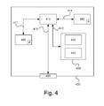
- Figure 4 depicts a diagram of one embodiment of a device 400.
- the fuel-level sensor 200 described with reference to e.g. Figure 2 can comprise the device 400.
- the control unit 240, the alarm system 270, the alarm configuration 280 and the electronic unit 290 can each comprise a device 400.
- the device 400 comprises a non-volatile memory 420, a data processing unit 410 and a read/write memory 450.
- the device 400 can also refer to a calculating device.
- the non-volatile memory 420 has a first memory element 430 in which a computer programme, e.g. an operating system, is stored for controlling the function of the device 400.
- the device 400 further comprises a bus controller, a serial communication port, I/O means, an A/D converter, a time and date input and transmission unit, an event counter and an interruption controller (not depicted).
- the non-volatile memory 420 has also a second memory element 440.
- a computer programme P comprising routines for detecting the abnormal removal of fuel from a fuel tank of a motor vehicle
- the programme P comprises routines for continuously detecting changes in the fuel quantity in said tank to determine whether said fuel quantity is being changed normally or otherwise.
- the programme P comprises routines for triggering a signal S1 if said fuel quantity is being changed abnormally.
- the programme P comprises routines for detecting the fuel level in said tank using a non-mechanical level sensor adapted to determine whether said fuel quantity is being changed normally or otherwise.
- the programme P comprises routines for transmitting said signal S1 using said level sensor to an existing alarm system 270 in the vehicle 100.
- the programme P comprises routines for encrypting said signal S1 before it is sent to the alarm system 270.
- a computer programme P comprising routines for determining whether, when and how an alarm should be triggered.
- the programme P comprises routines for determining whether an alarm should be triggered on the basis of the signal S1.
- the programme P comprises routines for decrypting said signal S1.
- a computer programme P comprising routines for automatically forwarding the signal S1 to the alarm system 270 without any discernible delay.
- the programme P may be stored in an executable form or compressed form in a memory 460 and/or in a read/write memory 450.
- the data processing unit 410 performs a certain function, it means that the data processing unit 410 performs a certain part of the programme which is stored in the memory 460 or a certain part of the programme which is stored in the read/write memory 450.
- the data processing device 410 can communicate with a data port 499 via a data bus 415.
- the non-volatile memory 420 is intended for communication with the data processing unit 410 via a data bus 412.
- the separate memory 460 is intended to communicate with the data processing unit 410 via a data bus 411.
- the read/write memory 450 is adapted to communicate with the data processing unit 410 via a data bus 414.
- the links L241, L242, L251, L261, L271, L281 and L291 can be connected to the data port 499 (see Figure 2 ).
- the data processing unit 410 When data are received on the data port 499, they are stored temporarily in the second memory element 440. The data processing unit 410 is ready to effect execution of codes in a form described above.
- Parts of the methods herein described can be performed by the device 400 by means of the data processing unit 410 which runs the programme stored in the memory 460 or the read/write memory 450. When the device 400 runs the programme, procedures herein described are executed.
Landscapes
- Engineering & Computer Science (AREA)
- Mechanical Engineering (AREA)
- Life Sciences & Earth Sciences (AREA)
- Sustainable Development (AREA)
- Sustainable Energy (AREA)
- Chemical & Material Sciences (AREA)
- Combustion & Propulsion (AREA)
- Transportation (AREA)
- Business, Economics & Management (AREA)
- Emergency Management (AREA)
- Physics & Mathematics (AREA)
- General Physics & Mathematics (AREA)
- Measurement Of Levels Of Liquids Or Fluent Solid Materials (AREA)
- Cooling, Air Intake And Gas Exhaust, And Fuel Tank Arrangements In Propulsion Units (AREA)
- Level Indicators Using A Float (AREA)
Abstract
- continuously detecting (s330) changes in the fuel quantity in said tank (230) to determine whether said fuel quantity is being changed normally or otherwise;
- triggering (s330) a signal (S1) if said fuel quantity is being changed abnormally,
- detecting the fuel level (L) in said tank (230) using a non-mechanical level sensor (200) adapted to determine whether said fuel quantity is being changed normally or otherwise; where
- said signal (S1) is transmitted by means of said level sensor (200) to an existing alarm system (270) in the vehicle (100; 110).
Description
- The present invention relates to a method for detecting the abnormal removal of fuel from a fuel tank of a motor vehicle.
- The invention relates also to a computer programme product comprising programme code for a computer for executing a method according to the invention.
- The invention also relates to a device for detecting the abnormal removal of fuel from a fuel tank of a motor vehicle and a motor vehicle equipped with the device.
- Motor vehicles equipped with a combustion engine often have a tank for holding fuel, such as petrol, ethanol or diesel. It has been evident for many years that this fuel is vulnerable to theft and various solutions have been put forward for detecting or preventing theft of said fuel.
- One method of stealing the fuel involves perpetrators opening or breaking open a tank lock to facilitate the removal of fuel using a tube. Another method involves perpetrators drilling a hole in the tank, similarly facilitating the removal of fuel using a tube.
- One system for detecting the abnormal removal of fuel from the tank, such as in the event of fuel theft, comprises a so-called float gauge adapted to detect an existing fuel level in the tank. The float gauge is adapted to communicate with a control unit. Said control unit is adapted with a logic system to determine an existing residual fuel quantity based on said detected fuel level and information, e.g. on the tank's geometric configuration. Said control unit is adapted to determine whether fuel has been removed from the tank in an abnormal way, based on information on an existing fuel level in the tank at different times. Said fuel gauges currently lack logic systems to determine whether fuel has been removed from the tank in an abnormal way.
- The control unit is adapted to communicate with an existing alarm system in the vehicle. In the event that the control unit has determined that the fuel has been removed in an abnormal way, a signal is sent to the alarm system to take the appropriate action.
- In this context, it is important to note that the control unit must be activated by connecting it to a power supply to enable processing of the information received from the float gauge. This naturally involves a certain amount of energy consumption. It is desirable to minimise electricity consumption in vehicles, in particular when the vehicle is switched off. It is also desirable to be able to determine whether fuel is being removed in an abnormal way when the vehicle is switched off.
-
GB 2469336 -
GB 2338308 - There is a need to find a reliable way to improve the ability to stop an ongoing fuel theft.
- There is a need to introduce a robust method for triggering an alarm in the event of fuel theft, where the fuel in a fuel tank of a motor vehicle is removed in an abnormal way.
- An object of the present invention is to propose a novel and advantageous method for detecting the abnormal removal of fuel from a fuel tank of a motor vehicle.
- Another object of the invention is to propose a novel and advantageous device and a novel and advantageous computer programme for detecting the abnormal removal of fuel from a fuel tank of a motor vehicle.
- A further object of the invention is to propose an alternative method, an alternative device and an alternative computer programme for achieving detection of the abnormal removal of fuel from a fuel tank of a motor vehicle.
- A further object of the invention is to propose a method, a device and a computer programme for triggering an alarm in a reliable way if the abnormal removal of fuel from a fuel tank of a motor vehicle is being carried out or has been carried out, in particular when the vehicle is switched off.
- These objects are achieved with a method for detecting the abnormal removal of fuel from a fuel tank of a motor vehicle, according to claim 1. According to one aspect of the invention, a method is proposed for detecting the abnormal removal of fuel from a fuel tank of a motor vehicle, comprising the steps of:
- continuously detecting changes in the fuel quantity in said tank to determine whether said fuel quantity is being changed normally or otherwise;
- triggering a signal if said fuel quantity is changed abnormally;
- detecting the fuel level in said tank using a non-mechanical level sensor adapted to determine whether said fuel quantity is being changed normally or otherwise;
- transmitting said signal using said level sensor to an existing alarm system in the vehicle.
- According to one embodiment, the alarm system can be resting, i.e. switched off, and activated by means of a signal from the non-mechanical level sensor. According to another embodiment, the alarm system can be active and adapted to follow preset routines when a signal is received from the non-mechanical level sensor.
- For this purpose, the non-mechanical level sensor can advantageously be equipped with the necessary logic system to both determine an existing fuel quantity and to determine whether changes in the fuel quantity are occurring in an abnormal way.
- This does not require information, e.g. on maximum tank volume or the fuel tank's geometric configuration, to be stored in a memory of the alarm system or other control unit.
- By providing a separate communication link between the non-mechanical level sensor and the alarm system, the logic system for determining an existing fuel level and the logic system for determining whether alarms should be triggered or not, can be separated.
- By providing a separate communication link between the non-mechanical level sensor and the alarm system, the logic system for determining changes over time to an existing fuel level and the logic system for determining whether alarms should be triggered or not, can be separated.
- In this way, a function for indicating fuel theft, which can be activated as required and not only when the vehicle (the vehicle's ignition) is switched off, is also achieved, which results in a versatile method according to one aspect of the invention.
- One advantage of the method according to one aspect of the invention is that the risk of false alarms can be minimised in that the alarm system takes account of other information, which information can comprise, e.g. information on prevailing operating conditions in the vehicle, information on a change in the vehicle's angle of tilt, information on prevailing conditions in a fuel warming device in the vehicle.
- The method can further comprise the step of detecting said fuel level by means of an ultrasonic sensor. In this way, a precise method for determining whether fuel theft is being carried out can be achieved. In this way, a method for determining whether a fuel theft is being carried out is also advantageously achieved, in which a control unit used according to the state of the art for this purpose, can be switched off.
- The method can further comprise the step of continuously transmitting said signal. In this way, a fairly precise method for determining whether fuel theft is being carried out is achieved. In this way, an alarm can be triggered relatively quickly after a fuel theft is initiated, hopefully interrupting the theft at an early stage and thereby minimising financial losses.
- Said signal can only comprise the result of said determination. In this way, a method according to one aspect of the invention is achieved, in that a minimum amount of information is collated in said signal, resulting in a rapid and effective solution which is not calculation-heavy.
- Said signal can be encrypted. In this way, a method according to one aspect of the invention is achieved, which is secure to the extent that a person intending to steal fuel from the tank and at the same time deceive the alarm system to prevent an alarm being triggered will find it difficult to establish a so-called theft coupling.
- The method can further comprise the step of sending said signal direct to said alarm system. In this way, the effect is achieved that the control unit(s), comprising, according to state of the art solutions, e.g. a float gauge, which are used to determine the extent to which a change in the fuel quantity in the tank has occurred in an abnormal way, can be deactivated, thereby reducing electricity consumption. In this way, a rapid and secure way of transferring information from the fuel-level sensor to the alarm system is also achieved.
- Said signal can comprise information on changes in said fuel quantity per unit of time. In this way, an effective basis is achieved enabling the alarm system to decide whether an alarm should be triggered, and if so, which alarm. In this way, an improved alarm system is achieved which can more effectively determine whether alarms should be triggered or not. In this way, the risk of false alarms, e.g. caused by leakage in the fuel tank can be minimised.
- The method can further comprise the step of determining whether alarms should be triggered using the alarm system. According to one aspect of the invention, the fuel-level sensor can advantageously be adapted to determine whether a fuel quantity in the fuel tank is being changed in an abnormal way. In this way, the alarm system does not need to include said logic systems or said drive routines, enabling the design of the alarm system to be less complex in this regard.
- The method can further comprise the step of triggering alarms by means of sound and/or light in the vehicle. In this way, any ongoing theft of fuel can be efficiently detected. In this way, the attention of the general public or of persons belonging to appropriate professional groups, such as guards, can also be effectively and reliably attracted.
- The method can further comprise the step of triggering alarms by means of a signal to an alarm configuration arranged at a distance from the vehicle. Said signal can comprise information on the vehicle's position. In this way, guards and/or police officers can be quickly, reliably and effectively directed to the vehicle's position.
- The method is easy to implement in existing motor vehicles. Software for detecting the abnormal removal of fuel from a fuel tank of a motor vehicle can be installed in advance in the fuel-level sensor of the vehicle during its manufacture. Software comprising programme code for carrying out the innovative method can be installed in the fuel-level sensor and the alarm system in the vehicle during a software upgrade at a service station. In this case, the software can be loaded into a memory in the fuel-level sensor and/or alarm system. Implementation of the innovative method is therefore cost-effective.
- Software that incorporates programme code for detecting the abnormal removal of fuel from a fuel tank of a motor vehicle can be easily be updated or replaced. Different components of the software which comprise programme code for carrying out the innovative method can also be replaced independently of one another. This modular configuration is advantageous from a maintenance perspective.
- According to one aspect of the invention, a device is proposed for detecting the abnormal removal of fuel from a fuel tank of a motor vehicle, comprising:
- elements for continuously detecting changes in the fuel quantity in said tank to determine whether said fuel quantity is being changed normally or otherwise;
- elements for triggering a signal if said fuel quantity is changed abnormally;
- elements for detecting the fuel level in said tank using a non-mechanical level sensor adapted to determine whether said fuel quantity is being changed normally or otherwise; where
- said level sensor is adapted to transmit said signal to an existing alarm system in the vehicle.
- The device can further comprise:
- elements for detecting said fuel level using an ultrasonic sensor.
- The device can further comprise:
- elements for continuously transmitting said signal.
- Said signal can only comprise the result of said determination.
- The device can further comprise:
- elements for encrypting said signal.
- The device can further comprise:
- elements for sending said signal direct to said alarm system.
- The device can further comprise:
- elements for determining information on changes in said fuel quantity per unit of time, and
- elements for collating said information in said signal.
- Said alarm system can be adapted to determine whether alarms should be triggered.
- The device can further comprise:
- elements for triggering alarms by means of sound and/or light in the vehicle.
- The device can further comprise:
- elements for triggering alarms by means of a signal to an alarm configuration arranged at a distance from the vehicle.
- The above objects are also achieved with a motor vehicle comprising the device. The motor vehicle can be a truck, bus, car, dump truck or crane truck.
- The motor vehicle can be a bucket loader, forestry machine or a vehicle adapted for operation in a mine.
- According to one aspect of the invention, a computer programme is proposed for detecting the abnormal removal of fuel from a fuel tank of a motor vehicle, where said computer programme comprises programme code stored on a computer-readable medium for causing an electronic device or a second computer to perform the steps according to any one of claims 1-10. Said electronic device can be a fuel-level sensor. Said second computer can be a computer incorporated into an alarm system in the vehicle.
- According to one aspect of the invention, a computer programme is proposed for detecting the abnormal removal of fuel from a fuel tank of a motor vehicle, where said computer programme comprises programme code for causing an electronic device or a second computer to perform the steps according to any one of claims 1-10. Said electronic device can be a fuel-level sensor. Said second computer can be a computer incorporated into an alarm system in the vehicle.
- According to one aspect of the invention, a computer programme product is proposed which comprises a programme code stored on a computer-readable medium for performing the method steps according to any one of claims 1-10, when said computer programme is run on an electronic device or a second computer connected to the electronic device. Said electronic device can be a fuel-level sensor. Said second computer can be a computer incorporated into an alarm system in the vehicle.
- According to one aspect of the invention, a computer programme is proposed for detecting the abnormal removal of fuel from a fuel tank of a motor vehicle, where said computer programme comprises programme code stored on a computer-readable medium for causing a fuel-level sensor to perform the steps according to any one of claims 1-7.
- According to one aspect of the invention, a computer programme is proposed for detecting the abnormal removal of fuel from a fuel tank of a motor vehicle, where said computer programme comprises programme code stored on a computer-readable medium for causing an alarm system to perform the steps of:
- determining whether alarms should be triggered and/or
- triggering alarms by means of sound and/or light in the vehicle, and/or
- triggering alarms by means of a signal to an alarm configuration arranged at a distance from the vehicle.
- According to one aspect of the invention, a computer programme is proposed for detecting the abnormal removal of fuel from a fuel tank of a motor vehicle, where said computer programme comprises programme code stored on a medium for causing an alarm system to perform the steps of:
- determining whether alarms should be triggered and/or
- triggering alarms by means of sound and/or light in the vehicle, and/or
- triggering alarms by means of a signal to an alarm configuration arranged at a distance from the vehicle.
- According to one aspect of the invention, a computer programme is proposed for detecting the abnormal removal of fuel from a fuel tank of a motor vehicle, where said computer programme comprises programme code for causing a fuel-level sensor to perform the steps according to any one of claims 1-7.
- According to one aspect of the invention, a computer programme product is proposed comprising a programme code stored on a computer-readable medium for performing the method steps according to any one of claims 1-7, when said computer programme is run on a processor of a fuel-level sensor.
- Further objects, advantages and novel features of the present invention will become apparent to one skilled in the art from the following details, and also by putting the invention into practice. Although the invention is described below, it should be noted that it is not limited to the specific details described. Persons skilled in the art, who have access to the teachings herein, will recognise further applications, modifications and incorporations within other fields, which are within the scope of the invention.
- For a more complete understanding of the present invention and further objects and advantages thereof, the detailed description set out below should be read together with the accompanying drawings, in which the same reference notations denote similar items in the various drawings, and in which:
-
Figure 1 illustrates schematically a vehicle according to one embodiment of the invention; -
Figure 2 illustrates schematically a subsystem for the vehicle depicted inFigure 1 , according to one embodiment of the invention; -
Figure 3a illustrates schematically flowchart of a method according to one embodiment of the invention; -
Figure 4b illustrates schematically in further detail a flowchart of a method according to one embodiment of the invention; and -
Figure 4 illustrates schematically a computer according to one embodiment of the invention. -
Figure 1 depicts a side view of avehicle 100. The exemplifiedvehicle 100 comprises atractor unit 110 with atrailer 112. The vehicle can be a heavy vehicle, such as a truck or bus. The vehicle can alternatively be a car. - The term "link" herein refers to a communication link that may be a physical connection such as an opto-electronic communication line, or a non-physical connection such as a wireless connection, e.g. a radio link or microwave link.
- The term "non-mechanical level sensor" herein refers to a level sensor which uses non-mechanical functionality to detect an existing quantity of fuel in the fuel tank of a vehicle, e.g. detection by means of light or sound. One example of a mechanical level sensor is a so-called float gauge, where a float is arranged around a rod in the tank to detect an existing quantity of fuel in the tank.
- The term "fuel quantity" herein refers to a measurement of the quantity of fuel in a fuel tank of the vehicle. The quantity of fuel can be shown as a fuel level in the tank or as a fuel volume. A detected fuel level can be easily converted to an equivalent fuel volume, and vice versa. In some respects, the terms "fuel quantity", "fuel level" and "fuel volume" can be different expressions of the same quantity.
-
Figure 2 depicts asubsystem 299 of thevehicle 100. The subsystem 229 is arranged in thetractor unit 110. - The subsystem 229 comprises a
fuel tank 230. Thefuel tank 230 is adapted to hold fuel, such as petrol, diesel or ethanol. Said fuel is intended to be supplied to a combustion engine (not depicted) in the vehicle. Thefuel tank 230 can be adapted to hold any appropriate maximum volume of fuel. Where said motor vehicle is a car, thefuel tank 230 can be adapted to hold a maximum of, e.g. 70 litres. Where said motor vehicle is a truck, thefuel tank 230 can be adapted to hold a maximum of, e.g. 1500 litres. - A fuel-
level sensor 200 is adapted to detect an existing quantity of fuel in thefuel tank 230. Said fuel-level sensor 200 is adapted to determine an existing quantity of fuel in thefuel tank 230. - The
fuel level sensor 200 comprises a calculating device, depicted in further detail inFigure 4 . The fuel-level sensor 200 can be adapted to detect an existing fuel level L in the tank. Said calculating device is adapted to calculate and determine a corresponding existing volume of fuel V in thetank 230, using routines and parameters stored in a memory. A parameter can comprise information on the fuel tank's 230 geometric configuration. In this way, each given fuel level L in thetank 230 corresponds to a volume of fuel V determined empirically in advance. In this way, with appropriate adaptations, the innovative method can thus be applied to different tanks with different respective geometric configurations. The fuel-level sensor 200 is adapted to determine an existing fuel level L in thetank 230 even when the fuel is disturbed and/or the vehicle is tilting relevant to a reference plane. - The fuel-
level sensor 200 can be adapted to continuously determine an existing fuel level L in thetank 230. Thefuel level sensor 200 can be adapted to continuously detect and determine an existing fuel level L in thetank 230. The fuel-level sensor 200 can be adapted to intermittently detect and determine an existing fuel level L in thetank 230. The fuel-level sensor 200 can be adapted to detect and determine an existing fuel level L in thetank 230 at any appropriate frequency, e.g. 1, 10 or 100Hz. Other possible frequencies can include once per minute or every ten minutes. - The fuel-
level sensor 200 can be adapted to determine whether an existing fuel quantity in thetank 230 is being changed abnormally or otherwise. For this, a first-order time derivative dV/dt of a fuel volume V in thetank 230 can be applied. Where it is established that dV/dt exceeds a preset threshold value Th, it can be established that said existing fuel volume V is being changed in an abnormal way. Where it is established that dV/dt is below said preset threshold value Th, it can be established that said existing fuel volume V is being changed in a normal way, e.g. through normal operation of the vehicle's combustion engine. - Where the vehicle is switched off, a comparison between a detected fuel level L1 at a first time t1 and detected fuel level L2 at a second time can be carried out. Said first time t1 and said second time t2 can be any appropriate time and differ by a time interval of, e.g. 5, 30 or 60 seconds. As no or negligible fuel consumption should occur in this case, it can be determined whether a fuel volume V in the
tank 230 is being changed in an abnormal way or otherwise. If L1 is essentially the same as L2, it can be determined that said fuel volume V in thetank 230 is being changed in a normal way, i.e. not at all or only negligibly. If L2 is less or substantially less than L1, it can be determined that said fuel volume V in thetank 230 is being changed in an abnormal way, e.g. due to a fuel theft that is being carried out or has been carried out. - Said fuel-
level sensor 200 can be a so-called ultrasonic sensor which can detect an existing fuel volume V in thetank 230 by means of ultrasonic elements. This can occur by continuously or intermittently transmitting ultrasonic signals and receiving reflected ultrasonic signals. The fuel-level sensor 200 is adapted to calculate and determine an existing fuel volume V in thetank 230 based on said transmitted ultrasonic signals and said reflected ultrasonic signals. - According to an alternative embodiment, said fuel-level sensor is adapted to detect an existing fuel volume V in the
tank 230 by means of sound waves at any appropriate frequency, amplitude and duration configuration. - Said fuel-
level sensor 200 can be a so-called light sensor which can detect an existing fuel volume V in thetank 230 by means of light elements. This can occur by continuously or intermittently transmitting light signals and receiving reflected light signals. The fuel-level sensor 200 is adapted to calculate and determine an existing fuel volume V in thetank 230 based on said transmitted light signals and said reflected light signals. - According to one embodiment, said fuel-level sensor is adapted to detect an existing fuel volume V in the
tank 230 by means of light waves at any appropriate frequency, amplitude and duration configuration. - According to one embodiment, said fuel-
level sensor 200 is attached to a roof of thefuel tank 230. Said fuel-level sensor 200 can alternatively be pre-attached to a wall of thefuel tank 230. According to one embodiment, said fuel-level sensor 200 can be pre-attached to the bottom of thefuel tank 230. - The fuel-
level sensor 200 is adapted to communicate with analarm system 270 via a link L271. - The fuel-
level sensor 200 is adapted to generate a signal S1 and transmit it directly to thealarm system 270 via the link L271. Said signal S1 can comprise information on an existing condition in thefuel tank 230. Said signal S1 can comprise information on whether an existing fuel quantity in thetank 230 is being changed normally or otherwise. Said signal can comprise detailed information on the rate of change of fuel volume V, detection schedules or other desired information calculated or otherwise determined by the fuel-level sensor 200. According to one embodiment, signal S1 comprises no information which can be interpreted to mean that no change to the existing fuel quantity has been determined. - According to one example, said signal S1 is only transmitted when the fuel-
level sensor 200 has determined that a fuel level L in the fuel tank has been changed in an abnormal way. - The
alarm system 270 can be any suitable alarm system. Thealarm system 270 is adapted to receive signals S1 from the fuel-level sensor 200 via the link L271. Thealarm system 270 is adapted to process the information in signal S1. Thealarm system 270 is adapted to determine whether alarms should be triggered based on the information in signal S1. Thealarm system 270 is adapted to determine which type of alarm or which combination of alarms should be triggered. Thealarm system 270 is adapted to determine when a possible alarm should be triggered directly or with a certain delay. Thealarm system 270 is adapted to determine when a possible alarm should be terminated. According to one example, thealarm system 270 is adapted to terminate an activated alarm when a fuel quantity in the fuel tank is no longer being changed in an abnormal way. According to a second example, the alarm system is adapted to terminate an activated alarm after a preset period of time has elapsed from the time said activation was initiated, e.g. 10, 30 or 60 minutes. According to a further example, thealarm system 270 is adapted to terminate an activated alarm when a manual action is taken, e.g. when a driver of the vehicle switches off the alarm using a signal switch. Said switch can be adapted for wireless communication with saidalarm system 270. - The
alarm system 270 is adapted to communicate with the sound-alarm element 250 via a link L251. The sound-alarm element 250 can comprise one or more sound-emitting means, such as amplifiers, loudspeakers and/or horns or similar. Said sound-alarm element 250 is adapted, where appropriate, to generate sound signals at any appropriate frequency, amplitude and duration configuration. Said sound-alarm element 250 is intended to scare away perpetrators when an ongoing fuel theft is detected or at least call the attention of the general public or the authorities to the fact that a fuel theft is being carried out or has been carried out. According to one embodiment, a sound signal equivalent to a burglar alarm is triggered by means of said sound-alarm element 250. This could take the form of a loud, intermittent, high-frequency sound causing discomfort to the human ear. - According to one example embodiment, the
alarm system 270 is adapted to communicate with the light-alarm element 260 via a link L261. The light-alarm element 260 can comprise one or more light-emitting means, such as spotlights, light sirens or similar. Said light-alarm element 260 is adapted, where appropriate, to generate light signals at any appropriate frequency, amplitude and duration configuration. Said light-alarm element 260 is intended to scare away perpetrators when an ongoing fuel theft is detected or at least call the attention of the general public or the authorities to the fact that a fuel theft is being carried out or has been carried out. According to one embodiment, a light signal equivalent to a burglar alarm is triggered by means of said light-alarm element 260. This could take the form of a flashing white light which may have a blinding or irritating effect on the human eye. - According to one example embodiment, the
alarm system 270 is adapted with an antenna (not depicted) to communicate with analarm configuration 280 via a link L281. Said antenna is adapted to transmit an alarm signal at an appropriate frequency, amplitude and duration configuration to thealarm configuration 280, for example via a satellite. Saidalarm configuration 280 can be arranged in an alarm control centre. The alarm control centre can be a manned alarm control centre, e.g. at a security company or police agency that can take measures to interrupt the fuel theft or track the perpetrators. According to one embodiment, saidalarm configuration 280 can be adapted to communicate with anelectronic unit 290 via a link L291. In this way, saidalarm configuration 280 can be adapted to automatically transmit a notification to theelectronic unit 290, e.g. a mobile telephone in the possession of a driver or vehicle owner. In this way, a driver or owner can be informed at an early stage if a fuel theft is being carried out or has recently been carried out. This can be advantageous, e.g. when the driver is sleeping in a cab of thevehicle 100. - The fuel-
level sensor 200 is connected to apower source 210 via acable 211. Thepower source 210 can be an existing vehicle battery. Thepower source 210 is adapted to connect the fuel-level sensor 200 to a power supply. Thepower source 210 can be a battery which is not said existing vehicle battery but a battery the sole purpose of which is to connect the fuel-level sensor 200 to a power supply. Thepower source 210 can be any appropriate power source in the vehicle. Thepower source 210 can be arranged externally to the fuel-level sensor 200 using said connectingcable 211. According to one embodiment, said power source is integrated into said fuel-level sensor 200. - The
first control unit 200 is adapted to communicate with acontrol unit 240 via a link L241. Thecontrol unit 240 is adapted to communicate with thealarm system 270 via a link L242. The fuel-level sensor 200 can be adapted to transmit said signals S1 to thecontrol unit 240. Thecontrol unit 240 can, inter alia, be adapted to control the vehicle's engine. Thecontrol unit 240 is adapted to be off when the vehicle is switched off. In this way, electricity consumption can be reduced over time. - According to one aspect of the invention, said signals S1 are transmitted directly to the
alarm system 270 without, according to state of the art embodiments, sending signals S1 to thecontrol unit 240. In this way, thecontrol unit 240 can be off when the vehicle is switched off, instead of either being activated by connection to a power supply or being continuously connected to a power supply and thereby activated. - According to one embodiment, it is however possible to use the
control unit 240 as a further transmission element. In this way, thecontrol unit 240 is adapted to receive said signals S1 from the fuel-level sensor via the link L241 and to further transmit these signals S1 to thealarm system 270 via the link L242. This is advantageous when the link L271 is unusable, e.g. due to sabotage during a fuel theft. It should be noted that no processing of the signals S1 or the information therein is carried out by thecontrol unit 240 according to this example embodiment. - The fuel-
level sensor 200 is adapted to detect the abnormal removal of fuel from a fuel tank of a motor vehicle. The fuel-level sensor 200 is adapted to continuously detect changes in the fuel quantity in thetank 230 to determine whether said fuel quantity is being changed normally or otherwise. The fuel-level sensor 200 is adapted to transmit a signal S1 if said fuel quantity is changed abnormally. The fuel-level sensor 200 is adapted to detect the fuel level L in saidtank 230 e.g. using sound or light at any appropriate frequency, amplitude and duration configuration and is in this way is also adapted to determine whether said fuel quantity is being changed normally or otherwise. The fuel-level sensor 200 is adapted to generate and transmit the signal S1 to an existingalarm system 270 in thevehicle 100. The fuel-level sensor 200 is adapted to continuously or intermittently transmit said signal S1. The fuel-level sensor 200 is adapted to encrypt said signal S1. Thealarm system 270 is adapted to decrypt said encrypted signal S1. According to one aspect of the invention, any appropriate encryption algorithm can be used for this purpose. -
Figure 3a schematically illustrates a flowchart of a method for detecting the abnormal removal of fuel from a fuel tank of a motor vehicle, according to one embodiment of the invention. The method comprises a first method step s301. The step s301 comprises the steps of: - continuously detecting changes in the fuel quantity in said tank to determine whether said fuel quantity is being changed normally or otherwise;
- emitting a signal if said fuel quantity is changed abnormally;
- detecting the fuel level in said tank using a non-mechanical level sensor adapted to determine whether said fuel quantity is being changed normally or otherwise;
- transmitting said signal using said level sensor to an existing alarm system in the vehicle. The method ends after step s301.
-
Figure 3b schematically illustrates in further detail a flowchart of a method for detecting the abnormal removal of fuel from afuel tank 230 of amotor vehicle 100, according to one embodiment of the invention. - The method comprises a first method step s310. The method step s310 comprises the step of detecting changes in the fuel quantity in the
tank 230 to determine whether said fuel quantity is being changed normally or otherwise. This can be performed by a non-mechanical sensor, e.g. anultrasonic sensor 200. Said changes in the fuel quantity can occur continuously or intermittently. Method step s310 is followed by a subsequent method step s320. - The method step s320 comprises the step of determining whether a change in the fuel quantity in the
tank 230 is abnormal or otherwise. This can be performed by taking account of whether the vehicle is in operation, e.g. if it is idling. If this is the case, a compensation for the fuel being consumed by a motor in the vehicle can be carried out. Compensation can also be carried out for other components in the vehicle operated by means of fuel from thetank 230. The step of determining whether a change in the fuel quantity in thetank 230 is abnormal or otherwise can be performed on the basis of a preset criterion, e.g. a rate of change of an existing fuel quantity in the fuel tank can be considered over a preset time interval. It should be noted that it is the fuel-level sensor 200 which determines in this case whether a fuel theft is being carried out or otherwise. The information contained in the signal S1 may therefore indicate that a fuel theft has been initiated, is being carried out or has been carried out, depending e.g. on the detection frequency in the fuel-level sensor. - It the change is abnormal, i.e. the result is positive, a subsequent method step s330 is carried out. If the change in the fuel quantity in the
tank 230 is not abnormal, i.e. the result is negative, the method ends. - The method step s330 comprises the step of transmitting a signal S1 to the
alarm system 270. Said signal S1 can be transmitted directly to thealarm system 270. The step s330 can also comprise the step of generating said signal S1 and thereby collating the appropriate information. Said information is intended to form the decision basis for thealarm system 270. Said signal S1 can also be encrypted according to one embodiment of the invention. - According to one alternative, a signal S1 can also be transmitted to the
alarm system 270 when the change in the fuel quantity in thetank 230 is normal. In this way, it can be indicated that a normal state prevails. This can be advantageous in that a continuous update is performed indicating that a signal contact between the fuel-level sensor 200 and thealarm system 270 exists. - Method step s330 is followed by a subsequent method step s340.
- The method step s340 comprises the step of determining whether an alarm should be triggered by the
alarm system 270. This can be performed in various ways. The step of determining whether an alarm should be triggered can be performed on the basis of different parameters. According to one embodiment, it can be determined that an alarm should be activated immediately. This can be appropriate if a fuel theft is ongoing. According to one embodiment, it can be determined that an alarm should be activated with a certain time lag. This can be advantageous when a driver is in the immediate vicinity, e.g. sleeping in a vehicle cab in the vehicle. In this way, it should be possible to avoid a confrontation between the perpetrator and the driver. According to one embodiment, it can be determined that an alarm should not be activated, even if the fuel-level sensor 200 has determined that a change in the fuel quantity in the fuel tank is abnormal. This can be advantageous in a case where the vehicle is inconveniently located and when the impact of an activate alarm on persons or equipment in the surroundings would be too negative. - The step of determining whether an alarm should be triggered also comprises the step, in the event that alarms should be triggered, of determining which alarms should be triggered. The step of determining whether an alarm should be triggered also comprises the step, in the event alarm should be triggered, of determining how said alarm should be triggered, e.g. by determining the frequency, amplitude and duration configuration of an alarm from the sound-
alarm device 250 or the light-alarm device 260. - If it is determined that an alarm should not be triggered, the method ends. If it is determined that an alarm should be triggered, directly or after a certain delay, a subsequent method step s350 is carried out.
- The method step s350 comprises the step of triggering an alarm by means of said
alarm system 270, e.g. comprising the sound-alarm element 250, the light-alarm element 260 and/or the antenna. Thealarm system 270 is adapted to control the activation and action of the triggered alarm. - The method ends after method step s350.
Figure 4 depicts a diagram of one embodiment of adevice 400. In one embodiment, the fuel-level sensor 200 described with reference to e.g.Figure 2 , can comprise thedevice 400. Thecontrol unit 240, thealarm system 270, thealarm configuration 280 and theelectronic unit 290 can each comprise adevice 400. - The
device 400 comprises anon-volatile memory 420, adata processing unit 410 and a read/write memory 450. Thedevice 400 can also refer to a calculating device. Thenon-volatile memory 420 has afirst memory element 430 in which a computer programme, e.g. an operating system, is stored for controlling the function of thedevice 400. Thedevice 400 further comprises a bus controller, a serial communication port, I/O means, an A/D converter, a time and date input and transmission unit, an event counter and an interruption controller (not depicted). Thenon-volatile memory 420 has also asecond memory element 440. - Where the
device 400 is arranged in the fuel-level sensor 200, a computer programme P is provided comprising routines for detecting the abnormal removal of fuel from a fuel tank of a motor vehicle The programme P comprises routines for continuously detecting changes in the fuel quantity in said tank to determine whether said fuel quantity is being changed normally or otherwise. The programme P comprises routines for triggering a signal S1 if said fuel quantity is being changed abnormally. The programme P comprises routines for detecting the fuel level in said tank using a non-mechanical level sensor adapted to determine whether said fuel quantity is being changed normally or otherwise. The programme P comprises routines for transmitting said signal S1 using said level sensor to an existingalarm system 270 in thevehicle 100. The programme P comprises routines for encrypting said signal S1 before it is sent to thealarm system 270. - Where the
device 400 is arranged in thealarm system 270, a computer programme P is provided, comprising routines for determining whether, when and how an alarm should be triggered. The programme P comprises routines for determining whether an alarm should be triggered on the basis of the signal S1. The programme P comprises routines for decrypting said signal S1. - Where the
device 400 is arranged in thecontrol unit 240, a computer programme P is provided, comprising routines for automatically forwarding the signal S1 to thealarm system 270 without any discernible delay. - The programme P may be stored in an executable form or compressed form in a
memory 460 and/or in a read/write memory 450. Where it is stated that thedata processing unit 410 performs a certain function, it means that thedata processing unit 410 performs a certain part of the programme which is stored in thememory 460 or a certain part of the programme which is stored in the read/write memory 450. Thedata processing device 410 can communicate with adata port 499 via adata bus 415. Thenon-volatile memory 420 is intended for communication with thedata processing unit 410 via adata bus 412. Theseparate memory 460 is intended to communicate with thedata processing unit 410 via adata bus 411. The read/write memory 450 is adapted to communicate with thedata processing unit 410 via adata bus 414. For example, the links L241, L242, L251, L261, L271, L281 and L291 can be connected to the data port 499 (seeFigure 2 ). - When data are received on the
data port 499, they are stored temporarily in thesecond memory element 440. Thedata processing unit 410 is ready to effect execution of codes in a form described above. - Parts of the methods herein described can be performed by the
device 400 by means of thedata processing unit 410 which runs the programme stored in thememory 460 or the read/write memory 450. When thedevice 400 runs the programme, procedures herein described are executed. - The foregoing description of the preferred embodiments of the present invention has been provided to illustrate and describe the invention. It is not intended to be exhaustive or to limit the invention to the variants described. Many modifications and variants will obviously suggest themselves to persons skilled in the art. The embodiments have been chosen and described in order best to make clear the principles of the invention and its practical applications and hence to make it possible for persons skilled in the art to understand the invention in its various embodiments and with the various modifications appropriate to the intended use.
Claims (24)
- Method for detecting the abnormal removal of fuel from a fuel tank (230) of a motor vehicle (100; 110), comprising the steps of:- continuously detecting (s330) changes in the fuel quantity in said tank (230) to determine whether said fuel quantity is being changed normally or otherwise;- transmitting (s320) a signal (S1) if said fuel quantity is changed abnormally, characterised by the steps of:- detecting a fuel level (L) in said tank (230) by means of a non-mechanical level sensor (200) adapted to determine (s320) whether said fuel quantity is being changed normally or otherwise, by using a first-order time derivative dV/dt of a fuel volume V in the tank (230) and, where it is established that dV/dt exceeds a preset threshold value Th, it can be established that said existing fuel volume is being changed in an abnormal way, or, where the vehicle is switched off, by comparing a detected fuel level L1 at a first time t1 and a detected fuel level L2 at a second time t2, if L2 is less or substantially less than L1, it can be established that said fuel volume V in the tank 230 is being changed in an abnormal way;- transmitting (s330) said signal (S1) by means of said level sensor (200) to an existing alarm system (270) in the vehicle (100; 110).
- Method according to claim 1, further comprising the step of:- detecting said fuel level (L) by means of an ultrasonic sensor (200).
- Method according to claim 1 or 2, further comprising the step of:- continuously transmitting said signal (S1).
- Method according to any one of claims 1-3, where said signal (S1) comprises only the result of said determination.
- Method according to any one of the foregoing claims, where said signal (S1) is encrypted.
- Method according to any one of the foregoing claims, further comprising the step of:- sending said signal (S1) directly to said alarm system (270).
- Method according to any one of the foregoing claims, where said signal (S1) comprises information on changes in said fuel quantity per unit of time.
- Method according to any one of the foregoing claims, further comprising the step of:- determining (s340) whether alarms should be triggered by means of the alarm system (270).
- Method according to any one of the foregoing claims, further comprising the step of:- triggering alarms (s350) by means of sound and/or light in the vehicle (100; 110).
- Method according to any one of the foregoing claims, further comprising the step of:- triggering alarms (s350) by means of a signal to an alarm configuration (280) arranged at a distance from the vehicle (100; 110).
- Device for detecting the abnormal removal of fuel from a fuel tank (230) of a motor vehicle (100; 110), comprising:- elements (200; 400) for continuously detecting changes in the fuel quantity in said tank (230) to determine whether said fuel quantity is being changed normally or otherwise;- element (200) for transmitting a signal (S1) if said fuel quantity is being changed abnormally,
characterised in that:- element (200) for detecting the fuel level (L) in said tank using a non-mechanical level sensor (200) comprising a calculating device (400) is adapted to determine whether said fuel quantity is being changed normally or otherwise; where- said fuel sensor (200) is adapted to transmit said signal (S1) to an existing alarm system (270) in the vehicle (100; 110). - Device according to claim 11, where said elements (200; 400) for detecting said fuel level (L) are an ultrasonic sensor (200).
- A device according to claim 11 or 12, further comprising:- elements (200; 400) for continuously transmitting said signal (S1).
- Device according to any one of claims 11-13, where said signal (S1) comprises only the result of said determination.
- Device according to any one of the claims, further comprising:- elements (200; 400) for encrypting said signal (S1).
- Device according to any one of claims 11-15, further comprising:- elements (200; 400) for sending said signal (S1) directly to said alarm system (270).
- Device according to any one of claims 11-16, further comprising:- elements (200; 400) for determining information on changes in said fuel quantity per unit of time, and- elements (200; 400) for collating said information in said signal (S1).
- Device according to any one of claims 11-17, where- said alarm system (270) is adapted to determine whether alarms should be triggered.
- Device according to any one of claims 11-18, further comprising:- elements (270; 250; 260) for triggering alarms by means of sound and/or light in the vehicle (100; 110).
- Device according to any one of the foregoing claims, further comprising:- element (270) for triggering alarms by means of a signal to an alarm configuration (280) arranged at a distance from the vehicle (100; 110).
- Motor vehicle (100; 110) comprising a device according to any one of claims 11-20.
- A motor vehicle (100; 110) according to claim 21, which motor vehicle is any from among a truck, bus or car.
- Computer programme (P) for detecting the abnormal removal of fuel from a fuel tank (230) of a motor vehicle (100; 110), where said computer programme (P) comprises programme code for causing an electronic device (200; 400) or second computer (270; 400) connected to the electronic device (200; 400), to perform the steps according to any one of claims 1-10.
- A computer programme product comprising a programme code stored on a computer-readable medium for performing the method steps according to any one of claims 1-10, which computer programme is run on an electronic device (200; 400) or a second computer (210; 400) connected to the electronic device (200; 400).
Applications Claiming Priority (1)
| Application Number | Priority Date | Filing Date | Title |
|---|---|---|---|
| SE1250012A SE537375C2 (en) | 2012-01-12 | 2012-01-12 | Apparatus and method for detecting abnormal removal of fuel from a fuel tank |
Publications (3)
| Publication Number | Publication Date |
|---|---|
| EP2615001A2 true EP2615001A2 (en) | 2013-07-17 |
| EP2615001A3 EP2615001A3 (en) | 2013-07-31 |
| EP2615001B1 EP2615001B1 (en) | 2017-10-11 |
Family
ID=47602904
Family Applications (1)
| Application Number | Title | Priority Date | Filing Date |
|---|---|---|---|
| EP12196927.3A Active EP2615001B1 (en) | 2012-01-12 | 2012-12-13 | Device and method for detecting the abnormal removal of fuel from a fuel tank |
Country Status (3)
| Country | Link |
|---|---|
| EP (1) | EP2615001B1 (en) |
| BR (1) | BR102013000374A2 (en) |
| SE (1) | SE537375C2 (en) |
Cited By (9)
| Publication number | Priority date | Publication date | Assignee | Title |
|---|---|---|---|---|
| JP5830162B2 (en) * | 2013-12-11 | 2015-12-09 | 株式会社小松製作所 | Work machine, work machine management system, and work machine management method |
| DE202017103250U1 (en) | 2017-05-04 | 2017-06-29 | Okm Gmbh | System for monitoring the fuel supply or the load on stationary land, air or water vehicles |
| CN109774459A (en) * | 2019-01-30 | 2019-05-21 | 北京福田戴姆勒汽车有限公司 | A kind of vehicle fuel amount abnormal alarm method and device |
| IT202000014650A1 (en) * | 2020-06-18 | 2020-09-18 | Salvatore Giamblanco | Procedure to prevent theft of fuel from the tank of commercial vehicles |
| CN111982223A (en) * | 2020-07-03 | 2020-11-24 | 智博汽车科技(上海)有限公司 | Oil quantity detection device and method and vehicle |
| IT201900020002A1 (en) * | 2019-10-29 | 2021-04-29 | Di Camillo Serbatoi S R L | IMPROVED TANK GROUP. |
| CN113051311A (en) * | 2021-03-16 | 2021-06-29 | 鱼快创领智能科技(南京)有限公司 | Method, system and device for monitoring abnormal change of liquid level of vehicle oil tank |
| CN116238324A (en) * | 2023-02-08 | 2023-06-09 | 东风华神汽车有限公司 | A fuel tank condition monitoring system and monitoring method |
| DE102024209180A1 (en) | 2024-09-24 | 2026-03-26 | Robert Bosch Gesellschaft mit beschränkter Haftung | Method for operating a direct-injection gas combustion engine, in particular a hydrogen engine |
Families Citing this family (1)
| Publication number | Priority date | Publication date | Assignee | Title |
|---|---|---|---|---|
| FR3137169A1 (en) * | 2022-06-23 | 2023-12-29 | Lionel Lecrosnier | Method for controlling the volume and detecting withdrawal of fuel contained in a road vehicle tank and Device for implementing this process |
Citations (2)
| Publication number | Priority date | Publication date | Assignee | Title |
|---|---|---|---|---|
| GB2338308A (en) | 1998-06-09 | 1999-12-15 | Graeme Michael Frankland | Device for monitoring rate of change in liquid level |
| GB2469336A (en) | 2009-04-09 | 2010-10-13 | Richard Scott | A fuel theft alarm for a vehicle fuel tank |
Family Cites Families (3)
| Publication number | Priority date | Publication date | Assignee | Title |
|---|---|---|---|---|
| US3925756A (en) * | 1974-07-22 | 1975-12-09 | Joseph Edwards | Vehicle fuel loss alarm |
| FR2476354A1 (en) * | 1980-02-18 | 1981-08-21 | Rey Jean Paul | Petrol anti-theft alarm - includes electronic circuit sensitive to movement of float controlled resistor normally driving petrol gauge |
| FR2932259B1 (en) * | 2008-06-06 | 2010-07-30 | Sita France | DEVICE FOR MONITORING THE LEVEL OF FUEL IN A VEHICLE TANK |
-
2012
- 2012-01-12 SE SE1250012A patent/SE537375C2/en unknown
- 2012-12-13 EP EP12196927.3A patent/EP2615001B1/en active Active
-
2013
- 2013-01-07 BR BRBR102013000374-3A patent/BR102013000374A2/en not_active Application Discontinuation
Patent Citations (2)
| Publication number | Priority date | Publication date | Assignee | Title |
|---|---|---|---|---|
| GB2338308A (en) | 1998-06-09 | 1999-12-15 | Graeme Michael Frankland | Device for monitoring rate of change in liquid level |
| GB2469336A (en) | 2009-04-09 | 2010-10-13 | Richard Scott | A fuel theft alarm for a vehicle fuel tank |
Cited By (13)
| Publication number | Priority date | Publication date | Assignee | Title |
|---|---|---|---|---|
| US9324200B2 (en) | 2013-12-11 | 2016-04-26 | Komatsu Ltd. | Work machine, control system for work machine, and control method for work machine |
| DE112013000265B4 (en) | 2013-12-11 | 2018-07-26 | Komatsu Ltd. | Work machine, control system for a work machine and control method for a work machine |
| JP5830162B2 (en) * | 2013-12-11 | 2015-12-09 | 株式会社小松製作所 | Work machine, work machine management system, and work machine management method |
| DE202017103250U1 (en) | 2017-05-04 | 2017-06-29 | Okm Gmbh | System for monitoring the fuel supply or the load on stationary land, air or water vehicles |
| EP3399508A2 (en) | 2017-05-04 | 2018-11-07 | OKM GmbH | System for monitoring the fuel level or the load on a stationary land, air or water vehicle |
| CN109774459A (en) * | 2019-01-30 | 2019-05-21 | 北京福田戴姆勒汽车有限公司 | A kind of vehicle fuel amount abnormal alarm method and device |
| IT201900020002A1 (en) * | 2019-10-29 | 2021-04-29 | Di Camillo Serbatoi S R L | IMPROVED TANK GROUP. |
| IT202000014650A1 (en) * | 2020-06-18 | 2020-09-18 | Salvatore Giamblanco | Procedure to prevent theft of fuel from the tank of commercial vehicles |
| CN111982223A (en) * | 2020-07-03 | 2020-11-24 | 智博汽车科技(上海)有限公司 | Oil quantity detection device and method and vehicle |
| CN113051311A (en) * | 2021-03-16 | 2021-06-29 | 鱼快创领智能科技(南京)有限公司 | Method, system and device for monitoring abnormal change of liquid level of vehicle oil tank |
| CN113051311B (en) * | 2021-03-16 | 2023-07-28 | 鱼快创领智能科技(南京)有限公司 | Method, system and device for monitoring abnormal change of liquid level of vehicle oil tank |
| CN116238324A (en) * | 2023-02-08 | 2023-06-09 | 东风华神汽车有限公司 | A fuel tank condition monitoring system and monitoring method |
| DE102024209180A1 (en) | 2024-09-24 | 2026-03-26 | Robert Bosch Gesellschaft mit beschränkter Haftung | Method for operating a direct-injection gas combustion engine, in particular a hydrogen engine |
Also Published As
| Publication number | Publication date |
|---|---|
| BR102013000374A2 (en) | 2015-05-12 |
| SE1250012A1 (en) | 2013-07-13 |
| EP2615001B1 (en) | 2017-10-11 |
| EP2615001A3 (en) | 2013-07-31 |
| SE537375C2 (en) | 2015-04-14 |
Similar Documents
| Publication | Publication Date | Title |
|---|---|---|
| EP2615001B1 (en) | Device and method for detecting the abnormal removal of fuel from a fuel tank | |
| US7637556B2 (en) | Truck security system | |
| US20060103516A1 (en) | Infant car seat alarm system and method | |
| US7298246B1 (en) | Vehicle security monitoring device | |
| CN102431522A (en) | Automobile anti-theft system | |
| US20170136989A1 (en) | Portable, self-contained anti-theft vehicle alarm system with automatic proximity control | |
| CN104129360A (en) | Automobile anti-theft device | |
| GB2501679A (en) | Fuel theft surveillance system | |
| CN105297781A (en) | Abnormity warning device for well lid | |
| CN110615054A (en) | Electric vehicle anti-theft alarm system based on NB-IOT | |
| GB2363884A (en) | Vehicle alarm system | |
| JP2004251024A (en) | Dangerous object detecting device for construction equipment | |
| KR20160017485A (en) | Human body sensing alarm system for safety operation of heavy equipment or large vehicle | |
| CN210617842U (en) | Vehicle oil tank anti-theft device | |
| CA3049592A1 (en) | Work vehicle fuel anti-theft system | |
| KR100981209B1 (en) | Motorcycle anti-theft device using ultrasonic sensor | |
| JP2004161121A (en) | Theft reporting device and emergency reporting system | |
| JP2013134589A (en) | On-vehicle alarm device and vehicle linkage alarm system | |
| JP2013133088A (en) | Theft detection device and theft detection system | |
| US20230264654A1 (en) | Catalytic converter alarm | |
| EP3043157A2 (en) | An apparatus for surveillance of a fuel system of a vehicle | |
| CN103507750A (en) | Message remote control anti-theft device and method | |
| JP4338343B2 (en) | Vehicle antitheft device, vehicle antitheft method, and vehicle antitheft program | |
| JP5293687B2 (en) | Abnormality reporting system | |
| EP2962908A1 (en) | Alarm device for protecting against the theft of fuel and batteries in lorries |
Legal Events
| Date | Code | Title | Description |
|---|---|---|---|
| PUAL | Search report despatched |
Free format text: ORIGINAL CODE: 0009013 |
|
| PUAI | Public reference made under article 153(3) epc to a published international application that has entered the european phase |
Free format text: ORIGINAL CODE: 0009012 |
|
| AK | Designated contracting states |
Kind code of ref document: A2 Designated state(s): AL AT BE BG CH CY CZ DE DK EE ES FI FR GB GR HR HU IE IS IT LI LT LU LV MC MK MT NL NO PL PT RO RS SE SI SK SM TR |
|
| AX | Request for extension of the european patent |
Extension state: BA ME |
|
| AK | Designated contracting states |
Kind code of ref document: A3 Designated state(s): AL AT BE BG CH CY CZ DE DK EE ES FI FR GB GR HR HU IE IS IT LI LT LU LV MC MK MT NL NO PL PT RO RS SE SI SK SM TR |
|
| AX | Request for extension of the european patent |
Extension state: BA ME |
|
| RIC1 | Information provided on ipc code assigned before grant |
Ipc: B60R 25/10 20130101AFI20130625BHEP |
|
| RIN1 | Information on inventor provided before grant (corrected) |
Inventor name: POPESCU, DANIEL Inventor name: WALLEBAECK, PETER Inventor name: SUNDELL, PETER |
|
| 17P | Request for examination filed |
Effective date: 20140131 |
|
| RBV | Designated contracting states (corrected) |
Designated state(s): AL AT BE BG CH CY CZ DE DK EE ES FI FR GB GR HR HU IE IS IT LI LT LU LV MC MK MT NL NO PL PT RO RS SE SI SK SM TR |
|
| 17Q | First examination report despatched |
Effective date: 20140610 |
|
| GRAP | Despatch of communication of intention to grant a patent |
Free format text: ORIGINAL CODE: EPIDOSNIGR1 |
|
| STAA | Information on the status of an ep patent application or granted ep patent |
Free format text: STATUS: GRANT OF PATENT IS INTENDED |
|
| INTG | Intention to grant announced |
Effective date: 20170522 |
|
| GRAS | Grant fee paid |
Free format text: ORIGINAL CODE: EPIDOSNIGR3 |
|
| GRAA | (expected) grant |
Free format text: ORIGINAL CODE: 0009210 |
|
| STAA | Information on the status of an ep patent application or granted ep patent |
Free format text: STATUS: THE PATENT HAS BEEN GRANTED |
|
| AK | Designated contracting states |
Kind code of ref document: B1 Designated state(s): AL AT BE BG CH CY CZ DE DK EE ES FI FR GB GR HR HU IE IS IT LI LT LU LV MC MK MT NL NO PL PT RO RS SE SI SK SM TR |
|
| REG | Reference to a national code |
Ref country code: GB Ref legal event code: FG4D |
|
| REG | Reference to a national code |
Ref country code: CH Ref legal event code: EP |
|
| REG | Reference to a national code |
Ref country code: IE Ref legal event code: FG4D |
|
| REG | Reference to a national code |
Ref country code: AT Ref legal event code: REF Ref document number: 935719 Country of ref document: AT Kind code of ref document: T Effective date: 20171115 |
|
| REG | Reference to a national code |
Ref country code: DE Ref legal event code: R096 Ref document number: 602012038342 Country of ref document: DE |
|
| REG | Reference to a national code |
Ref country code: NL Ref legal event code: MP Effective date: 20171011 |
|
| REG | Reference to a national code |
Ref country code: LT Ref legal event code: MG4D |
|
| REG | Reference to a national code |
Ref country code: AT Ref legal event code: MK05 Ref document number: 935719 Country of ref document: AT Kind code of ref document: T Effective date: 20171011 |
|
| PG25 | Lapsed in a contracting state [announced via postgrant information from national office to epo] |
Ref country code: NL Free format text: LAPSE BECAUSE OF FAILURE TO SUBMIT A TRANSLATION OF THE DESCRIPTION OR TO PAY THE FEE WITHIN THE PRESCRIBED TIME-LIMIT Effective date: 20171011 |
|
| PG25 | Lapsed in a contracting state [announced via postgrant information from national office to epo] |
Ref country code: ES Free format text: LAPSE BECAUSE OF FAILURE TO SUBMIT A TRANSLATION OF THE DESCRIPTION OR TO PAY THE FEE WITHIN THE PRESCRIBED TIME-LIMIT Effective date: 20171011 Ref country code: LT Free format text: LAPSE BECAUSE OF FAILURE TO SUBMIT A TRANSLATION OF THE DESCRIPTION OR TO PAY THE FEE WITHIN THE PRESCRIBED TIME-LIMIT Effective date: 20171011 Ref country code: SE Free format text: LAPSE BECAUSE OF FAILURE TO SUBMIT A TRANSLATION OF THE DESCRIPTION OR TO PAY THE FEE WITHIN THE PRESCRIBED TIME-LIMIT Effective date: 20171011 Ref country code: NO Free format text: LAPSE BECAUSE OF FAILURE TO SUBMIT A TRANSLATION OF THE DESCRIPTION OR TO PAY THE FEE WITHIN THE PRESCRIBED TIME-LIMIT Effective date: 20180111 Ref country code: FI Free format text: LAPSE BECAUSE OF FAILURE TO SUBMIT A TRANSLATION OF THE DESCRIPTION OR TO PAY THE FEE WITHIN THE PRESCRIBED TIME-LIMIT Effective date: 20171011 |
|
| PG25 | Lapsed in a contracting state [announced via postgrant information from national office to epo] |
Ref country code: RS Free format text: LAPSE BECAUSE OF FAILURE TO SUBMIT A TRANSLATION OF THE DESCRIPTION OR TO PAY THE FEE WITHIN THE PRESCRIBED TIME-LIMIT Effective date: 20171011 Ref country code: AT Free format text: LAPSE BECAUSE OF FAILURE TO SUBMIT A TRANSLATION OF THE DESCRIPTION OR TO PAY THE FEE WITHIN THE PRESCRIBED TIME-LIMIT Effective date: 20171011 Ref country code: HR Free format text: LAPSE BECAUSE OF FAILURE TO SUBMIT A TRANSLATION OF THE DESCRIPTION OR TO PAY THE FEE WITHIN THE PRESCRIBED TIME-LIMIT Effective date: 20171011 Ref country code: LV Free format text: LAPSE BECAUSE OF FAILURE TO SUBMIT A TRANSLATION OF THE DESCRIPTION OR TO PAY THE FEE WITHIN THE PRESCRIBED TIME-LIMIT Effective date: 20171011 Ref country code: IS Free format text: LAPSE BECAUSE OF FAILURE TO SUBMIT A TRANSLATION OF THE DESCRIPTION OR TO PAY THE FEE WITHIN THE PRESCRIBED TIME-LIMIT Effective date: 20180211 Ref country code: BG Free format text: LAPSE BECAUSE OF FAILURE TO SUBMIT A TRANSLATION OF THE DESCRIPTION OR TO PAY THE FEE WITHIN THE PRESCRIBED TIME-LIMIT Effective date: 20180111 Ref country code: GR Free format text: LAPSE BECAUSE OF FAILURE TO SUBMIT A TRANSLATION OF THE DESCRIPTION OR TO PAY THE FEE WITHIN THE PRESCRIBED TIME-LIMIT Effective date: 20180112 |
|
| REG | Reference to a national code |
Ref country code: DE Ref legal event code: R097 Ref document number: 602012038342 Country of ref document: DE |
|
| PG25 | Lapsed in a contracting state [announced via postgrant information from national office to epo] |
Ref country code: EE Free format text: LAPSE BECAUSE OF FAILURE TO SUBMIT A TRANSLATION OF THE DESCRIPTION OR TO PAY THE FEE WITHIN THE PRESCRIBED TIME-LIMIT Effective date: 20171011 Ref country code: DK Free format text: LAPSE BECAUSE OF FAILURE TO SUBMIT A TRANSLATION OF THE DESCRIPTION OR TO PAY THE FEE WITHIN THE PRESCRIBED TIME-LIMIT Effective date: 20171011 Ref country code: CZ Free format text: LAPSE BECAUSE OF FAILURE TO SUBMIT A TRANSLATION OF THE DESCRIPTION OR TO PAY THE FEE WITHIN THE PRESCRIBED TIME-LIMIT Effective date: 20171011 Ref country code: SK Free format text: LAPSE BECAUSE OF FAILURE TO SUBMIT A TRANSLATION OF THE DESCRIPTION OR TO PAY THE FEE WITHIN THE PRESCRIBED TIME-LIMIT Effective date: 20171011 |
|
| REG | Reference to a national code |
Ref country code: CH Ref legal event code: PL |
|
| PLBE | No opposition filed within time limit |
Free format text: ORIGINAL CODE: 0009261 |
|
| STAA | Information on the status of an ep patent application or granted ep patent |
Free format text: STATUS: NO OPPOSITION FILED WITHIN TIME LIMIT |
|
| PG25 | Lapsed in a contracting state [announced via postgrant information from national office to epo] |
Ref country code: SM Free format text: LAPSE BECAUSE OF FAILURE TO SUBMIT A TRANSLATION OF THE DESCRIPTION OR TO PAY THE FEE WITHIN THE PRESCRIBED TIME-LIMIT Effective date: 20171011 Ref country code: RO Free format text: LAPSE BECAUSE OF FAILURE TO SUBMIT A TRANSLATION OF THE DESCRIPTION OR TO PAY THE FEE WITHIN THE PRESCRIBED TIME-LIMIT Effective date: 20171011 Ref country code: IT Free format text: LAPSE BECAUSE OF FAILURE TO SUBMIT A TRANSLATION OF THE DESCRIPTION OR TO PAY THE FEE WITHIN THE PRESCRIBED TIME-LIMIT Effective date: 20171011 Ref country code: PL Free format text: LAPSE BECAUSE OF FAILURE TO SUBMIT A TRANSLATION OF THE DESCRIPTION OR TO PAY THE FEE WITHIN THE PRESCRIBED TIME-LIMIT Effective date: 20171011 |
|
| 26N | No opposition filed |
Effective date: 20180712 |
|
| REG | Reference to a national code |
Ref country code: IE Ref legal event code: MM4A |
|
| GBPC | Gb: european patent ceased through non-payment of renewal fee |
Effective date: 20180111 |
|
| PG25 | Lapsed in a contracting state [announced via postgrant information from national office to epo] |
Ref country code: MT Free format text: LAPSE BECAUSE OF NON-PAYMENT OF DUE FEES Effective date: 20171213 Ref country code: LU Free format text: LAPSE BECAUSE OF NON-PAYMENT OF DUE FEES Effective date: 20171213 |
|
| REG | Reference to a national code |
Ref country code: FR Ref legal event code: ST Effective date: 20180831 |
|
| REG | Reference to a national code |
Ref country code: BE Ref legal event code: MM Effective date: 20171231 |
|
| PG25 | Lapsed in a contracting state [announced via postgrant information from national office to epo] |
Ref country code: FR Free format text: LAPSE BECAUSE OF NON-PAYMENT OF DUE FEES Effective date: 20180102 Ref country code: IE Free format text: LAPSE BECAUSE OF NON-PAYMENT OF DUE FEES Effective date: 20171213 |
|
| PG25 | Lapsed in a contracting state [announced via postgrant information from national office to epo] |
Ref country code: LI Free format text: LAPSE BECAUSE OF NON-PAYMENT OF DUE FEES Effective date: 20171231 Ref country code: CH Free format text: LAPSE BECAUSE OF NON-PAYMENT OF DUE FEES Effective date: 20171231 Ref country code: GB Free format text: LAPSE BECAUSE OF NON-PAYMENT OF DUE FEES Effective date: 20180111 Ref country code: BE Free format text: LAPSE BECAUSE OF NON-PAYMENT OF DUE FEES Effective date: 20171231 Ref country code: SI Free format text: LAPSE BECAUSE OF FAILURE TO SUBMIT A TRANSLATION OF THE DESCRIPTION OR TO PAY THE FEE WITHIN THE PRESCRIBED TIME-LIMIT Effective date: 20171011 |
|
| PG25 | Lapsed in a contracting state [announced via postgrant information from national office to epo] |
Ref country code: HU Free format text: LAPSE BECAUSE OF FAILURE TO SUBMIT A TRANSLATION OF THE DESCRIPTION OR TO PAY THE FEE WITHIN THE PRESCRIBED TIME-LIMIT; INVALID AB INITIO Effective date: 20121213 Ref country code: MC Free format text: LAPSE BECAUSE OF FAILURE TO SUBMIT A TRANSLATION OF THE DESCRIPTION OR TO PAY THE FEE WITHIN THE PRESCRIBED TIME-LIMIT Effective date: 20171011 |
|
| PG25 | Lapsed in a contracting state [announced via postgrant information from national office to epo] |
Ref country code: CY Free format text: LAPSE BECAUSE OF NON-PAYMENT OF DUE FEES Effective date: 20171011 |
|
| PG25 | Lapsed in a contracting state [announced via postgrant information from national office to epo] |
Ref country code: MK Free format text: LAPSE BECAUSE OF FAILURE TO SUBMIT A TRANSLATION OF THE DESCRIPTION OR TO PAY THE FEE WITHIN THE PRESCRIBED TIME-LIMIT Effective date: 20171011 |
|
| PG25 | Lapsed in a contracting state [announced via postgrant information from national office to epo] |
Ref country code: TR Free format text: LAPSE BECAUSE OF FAILURE TO SUBMIT A TRANSLATION OF THE DESCRIPTION OR TO PAY THE FEE WITHIN THE PRESCRIBED TIME-LIMIT Effective date: 20171011 |
|
| PG25 | Lapsed in a contracting state [announced via postgrant information from national office to epo] |
Ref country code: PT Free format text: LAPSE BECAUSE OF FAILURE TO SUBMIT A TRANSLATION OF THE DESCRIPTION OR TO PAY THE FEE WITHIN THE PRESCRIBED TIME-LIMIT Effective date: 20171011 |
|
| PG25 | Lapsed in a contracting state [announced via postgrant information from national office to epo] |
Ref country code: AL Free format text: LAPSE BECAUSE OF FAILURE TO SUBMIT A TRANSLATION OF THE DESCRIPTION OR TO PAY THE FEE WITHIN THE PRESCRIBED TIME-LIMIT Effective date: 20171011 |
|
| P01 | Opt-out of the competence of the unified patent court (upc) registered |
Effective date: 20230518 |
|
| PGFP | Annual fee paid to national office [announced via postgrant information from national office to epo] |
Ref country code: DE Payment date: 20251028 Year of fee payment: 14 |