EP2612993B1 - Slotted turbine airfoil - Google Patents
Slotted turbine airfoil Download PDFInfo
- Publication number
- EP2612993B1 EP2612993B1 EP12199005.5A EP12199005A EP2612993B1 EP 2612993 B1 EP2612993 B1 EP 2612993B1 EP 12199005 A EP12199005 A EP 12199005A EP 2612993 B1 EP2612993 B1 EP 2612993B1
- Authority
- EP
- European Patent Office
- Prior art keywords
- turbine
- nozzle airfoil
- static nozzle
- airfoil
- Prior art date
- Legal status (The legal status is an assumption and is not a legal conclusion. Google has not performed a legal analysis and makes no representation as to the accuracy of the status listed.)
- Active
Links
Images

Classifications
-
- F—MECHANICAL ENGINEERING; LIGHTING; HEATING; WEAPONS; BLASTING
- F01—MACHINES OR ENGINES IN GENERAL; ENGINE PLANTS IN GENERAL; STEAM ENGINES
- F01D—NON-POSITIVE DISPLACEMENT MACHINES OR ENGINES, e.g. STEAM TURBINES
- F01D5/00—Blades; Blade-carrying members; Heating, heat-insulating, cooling or antivibration means on the blades or the members
- F01D5/12—Blades
- F01D5/14—Form or construction
- F01D5/18—Hollow blades, i.e. blades with cooling or heating channels or cavities; Heating, heat-insulating or cooling means on blades
- F01D5/187—Convection cooling
-
- F—MECHANICAL ENGINEERING; LIGHTING; HEATING; WEAPONS; BLASTING
- F01—MACHINES OR ENGINES IN GENERAL; ENGINE PLANTS IN GENERAL; STEAM ENGINES
- F01D—NON-POSITIVE DISPLACEMENT MACHINES OR ENGINES, e.g. STEAM TURBINES
- F01D25/00—Component parts, details, or accessories, not provided for in, or of interest apart from, other groups
- F01D25/32—Collecting of condensation water; Drainage ; Removing solid particles
-
- F—MECHANICAL ENGINEERING; LIGHTING; HEATING; WEAPONS; BLASTING
- F01—MACHINES OR ENGINES IN GENERAL; ENGINE PLANTS IN GENERAL; STEAM ENGINES
- F01D—NON-POSITIVE DISPLACEMENT MACHINES OR ENGINES, e.g. STEAM TURBINES
- F01D5/00—Blades; Blade-carrying members; Heating, heat-insulating, cooling or antivibration means on the blades or the members
- F01D5/12—Blades
- F01D5/14—Form or construction
- F01D5/147—Construction, i.e. structural features, e.g. of weight-saving hollow blades
-
- F—MECHANICAL ENGINEERING; LIGHTING; HEATING; WEAPONS; BLASTING
- F05—INDEXING SCHEMES RELATING TO ENGINES OR PUMPS IN VARIOUS SUBCLASSES OF CLASSES F01-F04
- F05B—INDEXING SCHEME RELATING TO WIND, SPRING, WEIGHT, INERTIA OR LIKE MOTORS, TO MACHINES OR ENGINES FOR LIQUIDS COVERED BY SUBCLASSES F03B, F03D AND F03G
- F05B2230/00—Manufacture
- F05B2230/20—Manufacture essentially without removing material
- F05B2230/23—Manufacture essentially without removing material by permanently joining parts together
- F05B2230/232—Manufacture essentially without removing material by permanently joining parts together by welding
-
- F—MECHANICAL ENGINEERING; LIGHTING; HEATING; WEAPONS; BLASTING
- F05—INDEXING SCHEMES RELATING TO ENGINES OR PUMPS IN VARIOUS SUBCLASSES OF CLASSES F01-F04
- F05B—INDEXING SCHEME RELATING TO WIND, SPRING, WEIGHT, INERTIA OR LIKE MOTORS, TO MACHINES OR ENGINES FOR LIQUIDS COVERED BY SUBCLASSES F03B, F03D AND F03G
- F05B2260/00—Function
- F05B2260/95—Preventing corrosion
-
- F—MECHANICAL ENGINEERING; LIGHTING; HEATING; WEAPONS; BLASTING
- F05—INDEXING SCHEMES RELATING TO ENGINES OR PUMPS IN VARIOUS SUBCLASSES OF CLASSES F01-F04
- F05D—INDEXING SCHEME FOR ASPECTS RELATING TO NON-POSITIVE-DISPLACEMENT MACHINES OR ENGINES, GAS-TURBINES OR JET-PROPULSION PLANTS
- F05D2220/00—Application
- F05D2220/30—Application in turbines
- F05D2220/31—Application in turbines in steam turbines
-
- F—MECHANICAL ENGINEERING; LIGHTING; HEATING; WEAPONS; BLASTING
- F05—INDEXING SCHEMES RELATING TO ENGINES OR PUMPS IN VARIOUS SUBCLASSES OF CLASSES F01-F04
- F05D—INDEXING SCHEME FOR ASPECTS RELATING TO NON-POSITIVE-DISPLACEMENT MACHINES OR ENGINES, GAS-TURBINES OR JET-PROPULSION PLANTS
- F05D2260/00—Function
- F05D2260/60—Fluid transfer
- F05D2260/602—Drainage
Definitions
- aspects of the invention include a turbine airfoil having a moisture diverting slot for increasing the efficiency of a turbine stage including that airfoil.
- the high speed and local wetness concentration of steam passing through these stages can erode the tip regions of rotating buckets, as well as the walls of the static nozzle airfoils.
- manufacturers conventionally harden the bucket airfoil leading edges near the tip region, or shield the area with satellite strips.
- Another conventional approach involves removing accumulated water through water drainage arrangements in the nozzle outer sidewalls (or, endwalls), or through pressure and/or suction slots made in hollow static nozzle airfoils.
- a first aspect of the invention includes a turbine static nozzle airfoil according to claim 1.
- a second aspect of the invention includes a turbine stator as defined in claim 9.
- a third aspect of the invention includes a turbine static nozzle as defined in claim 10.
- aspects of the invention include a turbine airfoil having a moisture diverting slot for increasing the efficiency of a turbine stage including that airfoil.
- the high speed and local wetness concentration of steam passing through these stages can erode the tip regions of rotating buckets, as well as the walls of the static nozzle airfoils.
- manufacturers conventionally harden the bucket airfoil leading edges near the tip region, or shield the area with satellite strips.
- Another conventional approach involves removing accumulated water through water drainage arrangements in the nozzle outer sidewalls (or, endwalls), or through pressure and/or suction slots made in hollow static nozzle airfoils.
- Moisture removal stages in the low pressure (LP) section of a steam turbine serve a couple of beneficial purposes. Removing moisture from the section reduces the erosion on the last stage rotating bucket. This prolongs the life of the bucket as well as preserves the profile shape of the bucket. Additionally, moisture removal improves performance by removing moisture droplets that can negatively affect the steam trajectory impacting the buckets. Poor steam trajectory can lead to reduced stage efficiency.
- prior attempts at moisture removal in the static nozzle assemblies of LP turbines are deficient in a number of ways.
- the prior "thin-walled" design where the walls of the turbine nozzle airfoil have a uniform thickness of approximately 4 millimeters (mm), allow for placement of the moisture removal slot proximate the trailing edge of the turbine airfoil. While the location of the slot in this "thin-walled” design helps to remove moisture from the face of the nozzle airfoil (as it is significantly downstream of the leading edge), the "thin walled" design is prone to manufacturability issues such as distortion due to the thinness of its walls.
- aspects of the invention include a turbine static nozzle airfoil having: a concave pressure wall having a slot extending therethrough; a convex suction wall adjoined with the concave pressure wall at respective end joints; and a pocket fluidly connected with the slot and located between the convex suction wall and the concave pressure wall, wherein at least one of the convex suction wall or the concave pressure wall includes a thinned segment proximate one of the respective end joints, the thinned segment configured to extend the pocket toward a trailing edge of the turbine static nozzle airfoil.
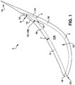
- FIG. 1 a side cross-sectional view of a turbine static nozzle airfoil (or, airfoil) 2 is shown according to embodiments of the invention.
- the turbine static nozzle airfoil 2 can include a convex suction wall 4 and a concave pressure wall 8 having a slot 6 extending therethrough.
- the concave pressure wall 8 can be adjoined with the convex suction wall 4 at respective end joints 10 (e.g., welds).
- the airfoil 2 can include a pocket 12 (specifically, sub-pocket 12B) fluidly connected with the slot 6 and located between the convex suction wall 4 and the concave pressure wall 8.
- the slot 6 fluidly connects to the sub-pocket 12B proximate a trailing edge of the sub-pocket 12B.
- at least one of the convex suction wall 4 or the concave pressure wall 8 includes a thinned segment 14, having a lesser thickness (t) than a remainder 16 (with thickness t') of the at least one of the convex suction wall 4 or the concave pressure wall 8.
- the thinned segment 14 is configured to extend the pocket 12 toward a trailing edge 18 of the turbine static nozzle airfoil 2 such that the slot 6 can be placed closer to that trailing edge 18 than in conventional moisture removal static nozzle airfoils.
- the slot 6 extends through the thinned segment 14, e.g., when the thinned segment is located within the concave pressure wall 8.
- FIG. 1 illustrates an embodiment (in phantom) where only the concave pressure wall 8 has a thinned segment 14, and the convex suction wall 4 has a substantially uniform thickness (as illustrated by the dashed line). It is understood that in another embodiment, illustrated in FIG. 2 , only the convex suction wall 4 includes the thinned segment 14, and the concave pressure wall 8 can have a substantially uniform thickness (as illustrated by the dashed line in that Figure). That is, in some cases, only one of the convex suction wall 4 or the concave pressure wall 8 can include the thinned segment 14. In other cases, both of the convex suction wall 4 and concave pressure wall 8 can include the thinned segment 14.
- the thinned segment(s) 14 extends the pocket 12 (forming sub-pocket 12B) toward the trailing edge 18.
- the thinned segment(s) 14 defines a neck 19 which forms sub-pockets 12A, 12B of pocket 12 between the convex suction wall 4 and the concave pressure wall 8.
- the thinned segment 14 is located proximate the end joint 10 located at the trailing edge 18 of the airfoil and the slot 6.
- the slot 6 can be located within (or, extend through) the thinned segment 14 of the concave pressure wall 8.
- the thinned segment 14 (and the slot 6) can be located proximate the trailing edge 18 of the airfoil 2. That is, the thinned segment 14 can abut (e.g., physically contact) the joint 10 (weld) located at the trailing edge 18 of the airfoil, where this joint 10 couples the convex suction wall 4 with the concave pressure wall 8.
- the airfoil 2 disclosed herein allows for location of the slot 6 approximately ten to twenty percent closer to the trailing edge 18 along the concave pressure wall 8. Location of the slot 6 in this case allows for more efficient moisture removal across the concave pressure wall 8.
- one or both of the convex suction wall 4 or the concave pressure wall 8 can include a thinned segment 14 having a lesser thickness (t) than a remainder 16 of the wall, where that remainder 16 has a second, larger thickness (t').
- This second thickness (t') in some cases can be approximately 1.5 to two times the lesser thickness (t). This can allow for placement of the slot 6 closer to the trailing edge 18 than in the conventional thick-walled designs while still preventing the manufacturing issues associated with the thin-walled designs.
- FIG. 2 shows a close-up side cross-sectional view of the airfoil 2 of FIG. 1 , which more clearly illustrates the relationship between the slot 6 and the thinned segment(s) 14.
- the thinned segment 14 allows for placement of the slot 6 closer to the trailing edge 18 than in the case where neither of the convex suction wall 4 nor the concave pressure wall 8 include a thinned segment 14 (as described with reference to the "thick-walled" example herein).
- FIG. 2 Also illustrated in FIG. 2 (in phantom) is the location of a moisture removal slot (or, prior art slot) PA according to the prior art "thick-walled" embodiments.
- the prior art slot PA is located farther from the trailing edge than the slot 6 formed according to embodiments of the invention. This is possible because of the thinned section 14 of at least one of the walls (4 or 8), which allows for placement of the slot 6 where a weld (such as end joint 10) would have previously been located.
- the slot 6 in the airfoil 2 according to embodiments of the invention is located ten to twenty percent closer the trailing edge 18 than in the prior art "thick-walled” example.
- FIG. 2 further shows a pocket termination reference point 21, which illustrates a location where the prior art pocket would have terminated using the "thick-walled" design.
- This pocket termination reference point 21 represents a junction of two nozzle airfoil walls (according to the prior art), each excluding the thinned segment 14. That is, without the use of at least one thinned segment 14 shown and described herein, the pocket (e.g., pocket 12) would not extend beyond the pocket termination reference point 21 toward the trailing edge 18. As shown, this allows the slot 6 to fluidly communicate with the pocket 12 (e.g., sub-pocket 12B) at a location between the pocket termination reference point 21 and the trailing edge 13 of the pocket 12.
- the pocket 12 e.g., sub-pocket 12B
- the prior art slot PA is located farther from the trailing edge 18, and is less effective in moisture removal.
- the thinned segment(s) 14 shown and disclosed herein extends the pocket (12) beyond the pocket termination point 21, allowing for formation of sub-pocket 12B and enhanced moisture removal as noted herein.
- Manufacturing the airfoil 2 can include separately hydro-forming the respective convex suction wall 4 and the concave pressure wall 8, where at least one of the walls (4, 8) includes a thinned segment 14. After hydro-forming the walls (4, 8), those walls can be welded together at respective joints 10 (proximate leading edge 20, FIG. 1 , and trailing edge 18, respectively) using a conventional welding technique such as gas tungsten arc welding (or, inert gas, TIG welding), gas metal arc welding (or, metal inert gas, MIG welding), etc.
- a conventional welding technique such as gas tungsten arc welding (or, inert gas, TIG welding), gas metal arc welding (or, metal inert gas, MIG welding), etc.
- the respective convex suction wall 4 and the concave pressure wall 8 can be molded, machined, or otherwise separately formed, and then welded together at respective joints 10.
- the airfoils 2 disclosed according to embodiments of the invention allow for placement of the slot 6 closer to the trailing edge 18 of the convex suction wall 4, thereby improving moisture removal in a turbine stage including one or more of these airfoil(s) 2.
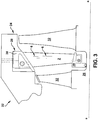
- FIG. 3 shows a plan view of a portion of a turbine 22 (e.g., a steam turbine such as a low pressure steam turbine section) according to aspects of the invention.
- the turbine 22 can include a turbine stator 24, which substantially surrounds a turbine rotor 26.
- the stator 24 can include axially dispersed sets of nozzles 28 (one set shown), where one or more of the axially dispersed sets of nozzles 28 can include a plurality of turbine static nozzle airfoils (e.g., airfoils 2 shown and described with reference to FIGS. 1-2 ).
- an entire set of nozzles 28 can include nozzle airfoils 2, and in some cases, a plurality of sets of nozzles 28 can include nozzle airfoils 2.
- each turbine static nozzle 2 in the set of nozzles 28 can include a pair of endwalls 30 and the nozzle airfoil 2 dispersed between and connected with each of the pair of endwalls 30.
- these turbine static nozzles 28 remain fixed within the stator 24 during operation of the turbine 22 and direct a working fluid toward rotating blades 32 of the rotor 26 to induce motion of the rotor's shaft (not shown, but aligned with axis a-a, as is known in the art).
- at least one of these sets of nozzles 28 in the turbine 22 can be configured to remove moisture from the airfoil faces (concave pressure side 4) using one or more slots 6.
Landscapes
- Engineering & Computer Science (AREA)
- Mechanical Engineering (AREA)
- General Engineering & Computer Science (AREA)
- Architecture (AREA)
- Turbine Rotor Nozzle Sealing (AREA)
Applications Claiming Priority (1)
| Application Number | Priority Date | Filing Date | Title |
|---|---|---|---|
| IT000010A ITMI20120010A1 (it) | 2012-01-05 | 2012-01-05 | Profilo aerodinamico di turbina a fessura |
Publications (2)
| Publication Number | Publication Date |
|---|---|
| EP2612993A1 EP2612993A1 (en) | 2013-07-10 |
| EP2612993B1 true EP2612993B1 (en) | 2018-07-04 |
Family
ID=45561006
Family Applications (1)
| Application Number | Title | Priority Date | Filing Date |
|---|---|---|---|
| EP12199005.5A Active EP2612993B1 (en) | 2012-01-05 | 2012-12-21 | Slotted turbine airfoil |
Country Status (6)
| Country | Link |
|---|---|
| US (1) | US8998571B2 (enExample) |
| EP (1) | EP2612993B1 (enExample) |
| JP (1) | JP6002028B2 (enExample) |
| CN (1) | CN103195495B (enExample) |
| IT (1) | ITMI20120010A1 (enExample) |
| RU (1) | RU2012158352A (enExample) |
Families Citing this family (11)
| Publication number | Priority date | Publication date | Assignee | Title |
|---|---|---|---|---|
| JP6230383B2 (ja) * | 2013-11-21 | 2017-11-15 | 三菱日立パワーシステムズ株式会社 | 蒸気タービンの静翼と蒸気タービン |
| EP3081751B1 (en) * | 2015-04-14 | 2020-10-21 | Ansaldo Energia Switzerland AG | Cooled airfoil and method for manufacturing said airfoil |
| US10781722B2 (en) | 2015-12-11 | 2020-09-22 | General Electric Company | Steam turbine, a steam turbine nozzle, and a method of managing moisture in a steam turbine |
| EP3318750B1 (en) * | 2016-11-02 | 2019-09-11 | Caren Meicnic Teoranta | An airfoil and a turbine apparatus |
| JP6944841B2 (ja) * | 2017-09-05 | 2021-10-06 | 三菱パワー株式会社 | 蒸気タービン翼、蒸気タービン、及び蒸気タービン翼の製造方法 |
| JP6944314B2 (ja) * | 2017-09-05 | 2021-10-06 | 三菱パワー株式会社 | 蒸気タービン翼の製造方法、蒸気タービン翼、及び蒸気タービン |
| WO2019049703A1 (ja) * | 2017-09-05 | 2019-03-14 | 三菱日立パワーシステムズ株式会社 | 蒸気タービン翼、蒸気タービン、及び蒸気タービン翼の製造方法 |
| JP7002890B2 (ja) * | 2017-09-05 | 2022-01-20 | 三菱パワー株式会社 | 蒸気タービン翼 |
| KR102048863B1 (ko) * | 2018-04-17 | 2019-11-26 | 두산중공업 주식회사 | 인서트 지지부를 구비한 터빈 베인 |
| JP7378970B2 (ja) * | 2019-06-10 | 2023-11-14 | 三菱重工業株式会社 | 蒸気タービン静翼、蒸気タービンおよび蒸気タービン静翼の製造方法 |
| JP7756748B1 (ja) | 2024-05-01 | 2025-10-20 | 三菱重工業株式会社 | 静翼セグメント、及びこれを備える蒸気タービン |
Citations (1)
| Publication number | Priority date | Publication date | Assignee | Title |
|---|---|---|---|---|
| JPS6445904A (en) * | 1987-08-13 | 1989-02-20 | Toshiba Corp | Steam turbine nozzle |
Family Cites Families (17)
| Publication number | Priority date | Publication date | Assignee | Title |
|---|---|---|---|---|
| GB893706A (en) * | 1960-01-05 | 1962-04-11 | Rolls Royce | Blades for fluid flow machines |
| US3420502A (en) * | 1962-09-04 | 1969-01-07 | Gen Electric | Fluid-cooled airfoil |
| US3881842A (en) | 1973-04-10 | 1975-05-06 | Jury Fedorovich Kosyak | Diaphragm for steam turbine stage |
| US4025226A (en) * | 1975-10-03 | 1977-05-24 | United Technologies Corporation | Air cooled turbine vane |
| US4137462A (en) | 1977-10-31 | 1979-01-30 | Westinghouse Electric Corp. | Probe for measuring steam quality |
| JP3170135B2 (ja) * | 1994-02-18 | 2001-05-28 | 三菱重工業株式会社 | ガスタービン翼の製造方法 |
| US5931638A (en) * | 1997-08-07 | 1999-08-03 | United Technologies Corporation | Turbomachinery airfoil with optimized heat transfer |
| US6234754B1 (en) * | 1999-08-09 | 2001-05-22 | United Technologies Corporation | Coolable airfoil structure |
| US6454526B1 (en) * | 2000-09-28 | 2002-09-24 | Siemens Westinghouse Power Corporation | Cooled turbine vane with endcaps |
| US6612811B2 (en) * | 2001-12-12 | 2003-09-02 | General Electric Company | Airfoil for a turbine nozzle of a gas turbine engine and method of making same |
| US6602047B1 (en) * | 2002-02-28 | 2003-08-05 | General Electric Company | Methods and apparatus for cooling gas turbine nozzles |
| US7156620B2 (en) * | 2004-12-21 | 2007-01-02 | Pratt & Whitney Canada Corp. | Internally cooled gas turbine airfoil and method |
| US7422415B2 (en) | 2006-05-23 | 2008-09-09 | General Electric Company | Airfoil and method for moisture removal and steam injection |
| US7780415B2 (en) * | 2007-02-15 | 2010-08-24 | Siemens Energy, Inc. | Turbine blade having a convergent cavity cooling system for a trailing edge |
| US7946815B2 (en) * | 2007-03-27 | 2011-05-24 | Siemens Energy, Inc. | Airfoil for a gas turbine engine |
| US7762775B1 (en) * | 2007-05-31 | 2010-07-27 | Florida Turbine Technologies, Inc. | Turbine airfoil with cooled thin trailing edge |
| US8096771B2 (en) * | 2008-09-25 | 2012-01-17 | Siemens Energy, Inc. | Trailing edge cooling slot configuration for a turbine airfoil |
-
2012
- 2012-01-05 IT IT000010A patent/ITMI20120010A1/it unknown
- 2012-04-24 US US13/454,757 patent/US8998571B2/en active Active
- 2012-12-21 EP EP12199005.5A patent/EP2612993B1/en active Active
- 2012-12-26 JP JP2012281922A patent/JP6002028B2/ja not_active Expired - Fee Related
- 2012-12-27 RU RU2012158352/06A patent/RU2012158352A/ru not_active Application Discontinuation
-
2013
- 2013-01-05 CN CN201310001646.7A patent/CN103195495B/zh not_active Expired - Fee Related
Patent Citations (1)
| Publication number | Priority date | Publication date | Assignee | Title |
|---|---|---|---|---|
| JPS6445904A (en) * | 1987-08-13 | 1989-02-20 | Toshiba Corp | Steam turbine nozzle |
Also Published As
| Publication number | Publication date |
|---|---|
| ITMI20120010A1 (it) | 2013-07-06 |
| JP2013139807A (ja) | 2013-07-18 |
| US20130177397A1 (en) | 2013-07-11 |
| US8998571B2 (en) | 2015-04-07 |
| JP6002028B2 (ja) | 2016-10-05 |
| EP2612993A1 (en) | 2013-07-10 |
| CN103195495A (zh) | 2013-07-10 |
| RU2012158352A (ru) | 2014-07-10 |
| CN103195495B (zh) | 2016-03-23 |
Similar Documents
| Publication | Publication Date | Title |
|---|---|---|
| EP2612993B1 (en) | Slotted turbine airfoil | |
| CN102472111B (zh) | 叶片 | |
| CN101059083B (zh) | 导流隔板组件的装置和方法 | |
| EP2809885B1 (en) | Rotary fan blade and corresponding assembly | |
| EP2692990B1 (en) | Steam turbine stationary blade and corresponding steam turbine | |
| US20120014803A1 (en) | Turbine blade having material block and related method | |
| EP2282013A2 (en) | Moisture removal provisions for steam turbine | |
| US20110200430A1 (en) | Steam turbine nozzle segment having arcuate interface | |
| CN103244198A (zh) | 涡轮组件 | |
| US20150267548A1 (en) | Group of blade rows | |
| EP3205870B1 (en) | Stator-vane structure and turbofan engine employing same | |
| US11149549B2 (en) | Blade of steam turbine and steam turbine | |
| RU2692597C2 (ru) | Лопатка для турбомашины, содержащая аэродинамическую часть, способ изготовления такой лопатки и турбомашина, содержащая такие лопатки | |
| EP3177811B1 (en) | Gas turbine engine compressor | |
| CN111742115B (zh) | 用于飞行器涡轮机的叶片 | |
| JP2008196488A (ja) | 蒸気タービン用のブリングノズル/キャリア接合部設計 | |
| US8777564B2 (en) | Hybrid flow blade design | |
| WO2020250596A1 (ja) | 蒸気タービン静翼、蒸気タービンおよび蒸気タービン静翼の製造方法 | |
| KR20210036270A (ko) | 터보 기계의 블레이드 | |
| EP2985426B1 (en) | Blade device for a turbine and corresponding manufacturing method | |
| CN109312626B (zh) | 用于涡轮隔板的静止叶片及相关联的涡轮隔板 | |
| JP2007270833A (ja) | 形状を局所的に再加工したステータ翼とこのような翼を備えるステータ部分、圧縮ステージ、圧縮機およびターボ機械 | |
| US9945238B2 (en) | Steam turbine | |
| US9394797B2 (en) | Turbomachine nozzle having fluid conduit and related turbomachine | |
| IL272567B1 (en) | Moving blade of a turbo machine |
Legal Events
| Date | Code | Title | Description |
|---|---|---|---|
| PUAI | Public reference made under article 153(3) epc to a published international application that has entered the european phase |
Free format text: ORIGINAL CODE: 0009012 |
|
| AK | Designated contracting states |
Kind code of ref document: A1 Designated state(s): AL AT BE BG CH CY CZ DE DK EE ES FI FR GB GR HR HU IE IS IT LI LT LU LV MC MK MT NL NO PL PT RO RS SE SI SK SM TR |
|
| AX | Request for extension of the european patent |
Extension state: BA ME |
|
| 17P | Request for examination filed |
Effective date: 20140110 |
|
| RBV | Designated contracting states (corrected) |
Designated state(s): AL AT BE BG CH CY CZ DE DK EE ES FI FR GB GR HR HU IE IS IT LI LT LU LV MC MK MT NL NO PL PT RO RS SE SI SK SM TR |
|
| 17Q | First examination report despatched |
Effective date: 20170220 |
|
| REG | Reference to a national code |
Ref country code: DE Ref legal event code: R079 Ref document number: 602012048027 Country of ref document: DE Free format text: PREVIOUS MAIN CLASS: F01D0005180000 Ipc: F01D0005140000 |
|
| GRAP | Despatch of communication of intention to grant a patent |
Free format text: ORIGINAL CODE: EPIDOSNIGR1 |
|
| RIC1 | Information provided on ipc code assigned before grant |
Ipc: F01D 25/32 20060101ALI20180201BHEP Ipc: F01D 5/14 20060101AFI20180201BHEP |
|
| INTG | Intention to grant announced |
Effective date: 20180222 |
|
| GRAS | Grant fee paid |
Free format text: ORIGINAL CODE: EPIDOSNIGR3 |
|
| GRAA | (expected) grant |
Free format text: ORIGINAL CODE: 0009210 |
|
| AK | Designated contracting states |
Kind code of ref document: B1 Designated state(s): AL AT BE BG CH CY CZ DE DK EE ES FI FR GB GR HR HU IE IS IT LI LT LU LV MC MK MT NL NO PL PT RO RS SE SI SK SM TR |
|
| REG | Reference to a national code |
Ref country code: GB Ref legal event code: FG4D |
|
| REG | Reference to a national code |
Ref country code: CH Ref legal event code: EP |
|
| REG | Reference to a national code |
Ref country code: AT Ref legal event code: REF Ref document number: 1014723 Country of ref document: AT Kind code of ref document: T Effective date: 20180715 |
|
| REG | Reference to a national code |
Ref country code: IE Ref legal event code: FG4D |
|
| REG | Reference to a national code |
Ref country code: DE Ref legal event code: R096 Ref document number: 602012048027 Country of ref document: DE |
|
| REG | Reference to a national code |
Ref country code: NL Ref legal event code: MP Effective date: 20180704 |
|
| REG | Reference to a national code |
Ref country code: LT Ref legal event code: MG4D |
|
| REG | Reference to a national code |
Ref country code: AT Ref legal event code: MK05 Ref document number: 1014723 Country of ref document: AT Kind code of ref document: T Effective date: 20180704 |
|
| PG25 | Lapsed in a contracting state [announced via postgrant information from national office to epo] |
Ref country code: NL Free format text: LAPSE BECAUSE OF FAILURE TO SUBMIT A TRANSLATION OF THE DESCRIPTION OR TO PAY THE FEE WITHIN THE PRESCRIBED TIME-LIMIT Effective date: 20180704 |
|
| PG25 | Lapsed in a contracting state [announced via postgrant information from national office to epo] |
Ref country code: GR Free format text: LAPSE BECAUSE OF FAILURE TO SUBMIT A TRANSLATION OF THE DESCRIPTION OR TO PAY THE FEE WITHIN THE PRESCRIBED TIME-LIMIT Effective date: 20181005 Ref country code: NO Free format text: LAPSE BECAUSE OF FAILURE TO SUBMIT A TRANSLATION OF THE DESCRIPTION OR TO PAY THE FEE WITHIN THE PRESCRIBED TIME-LIMIT Effective date: 20181004 Ref country code: RS Free format text: LAPSE BECAUSE OF FAILURE TO SUBMIT A TRANSLATION OF THE DESCRIPTION OR TO PAY THE FEE WITHIN THE PRESCRIBED TIME-LIMIT Effective date: 20180704 Ref country code: SE Free format text: LAPSE BECAUSE OF FAILURE TO SUBMIT A TRANSLATION OF THE DESCRIPTION OR TO PAY THE FEE WITHIN THE PRESCRIBED TIME-LIMIT Effective date: 20180704 Ref country code: FI Free format text: LAPSE BECAUSE OF FAILURE TO SUBMIT A TRANSLATION OF THE DESCRIPTION OR TO PAY THE FEE WITHIN THE PRESCRIBED TIME-LIMIT Effective date: 20180704 Ref country code: PL Free format text: LAPSE BECAUSE OF FAILURE TO SUBMIT A TRANSLATION OF THE DESCRIPTION OR TO PAY THE FEE WITHIN THE PRESCRIBED TIME-LIMIT Effective date: 20180704 Ref country code: CZ Free format text: LAPSE BECAUSE OF FAILURE TO SUBMIT A TRANSLATION OF THE DESCRIPTION OR TO PAY THE FEE WITHIN THE PRESCRIBED TIME-LIMIT Effective date: 20180704 Ref country code: IS Free format text: LAPSE BECAUSE OF FAILURE TO SUBMIT A TRANSLATION OF THE DESCRIPTION OR TO PAY THE FEE WITHIN THE PRESCRIBED TIME-LIMIT Effective date: 20181104 Ref country code: AT Free format text: LAPSE BECAUSE OF FAILURE TO SUBMIT A TRANSLATION OF THE DESCRIPTION OR TO PAY THE FEE WITHIN THE PRESCRIBED TIME-LIMIT Effective date: 20180704 Ref country code: LT Free format text: LAPSE BECAUSE OF FAILURE TO SUBMIT A TRANSLATION OF THE DESCRIPTION OR TO PAY THE FEE WITHIN THE PRESCRIBED TIME-LIMIT Effective date: 20180704 Ref country code: BG Free format text: LAPSE BECAUSE OF FAILURE TO SUBMIT A TRANSLATION OF THE DESCRIPTION OR TO PAY THE FEE WITHIN THE PRESCRIBED TIME-LIMIT Effective date: 20181004 |
|
| PG25 | Lapsed in a contracting state [announced via postgrant information from national office to epo] |
Ref country code: AL Free format text: LAPSE BECAUSE OF FAILURE TO SUBMIT A TRANSLATION OF THE DESCRIPTION OR TO PAY THE FEE WITHIN THE PRESCRIBED TIME-LIMIT Effective date: 20180704 Ref country code: ES Free format text: LAPSE BECAUSE OF FAILURE TO SUBMIT A TRANSLATION OF THE DESCRIPTION OR TO PAY THE FEE WITHIN THE PRESCRIBED TIME-LIMIT Effective date: 20180704 Ref country code: LV Free format text: LAPSE BECAUSE OF FAILURE TO SUBMIT A TRANSLATION OF THE DESCRIPTION OR TO PAY THE FEE WITHIN THE PRESCRIBED TIME-LIMIT Effective date: 20180704 Ref country code: HR Free format text: LAPSE BECAUSE OF FAILURE TO SUBMIT A TRANSLATION OF THE DESCRIPTION OR TO PAY THE FEE WITHIN THE PRESCRIBED TIME-LIMIT Effective date: 20180704 |
|
| REG | Reference to a national code |
Ref country code: DE Ref legal event code: R097 Ref document number: 602012048027 Country of ref document: DE |
|
| PG25 | Lapsed in a contracting state [announced via postgrant information from national office to epo] |
Ref country code: EE Free format text: LAPSE BECAUSE OF FAILURE TO SUBMIT A TRANSLATION OF THE DESCRIPTION OR TO PAY THE FEE WITHIN THE PRESCRIBED TIME-LIMIT Effective date: 20180704 Ref country code: RO Free format text: LAPSE BECAUSE OF FAILURE TO SUBMIT A TRANSLATION OF THE DESCRIPTION OR TO PAY THE FEE WITHIN THE PRESCRIBED TIME-LIMIT Effective date: 20180704 |
|
| PLBE | No opposition filed within time limit |
Free format text: ORIGINAL CODE: 0009261 |
|
| STAA | Information on the status of an ep patent application or granted ep patent |
Free format text: STATUS: NO OPPOSITION FILED WITHIN TIME LIMIT |
|
| PG25 | Lapsed in a contracting state [announced via postgrant information from national office to epo] |
Ref country code: SK Free format text: LAPSE BECAUSE OF FAILURE TO SUBMIT A TRANSLATION OF THE DESCRIPTION OR TO PAY THE FEE WITHIN THE PRESCRIBED TIME-LIMIT Effective date: 20180704 Ref country code: SM Free format text: LAPSE BECAUSE OF FAILURE TO SUBMIT A TRANSLATION OF THE DESCRIPTION OR TO PAY THE FEE WITHIN THE PRESCRIBED TIME-LIMIT Effective date: 20180704 Ref country code: DK Free format text: LAPSE BECAUSE OF FAILURE TO SUBMIT A TRANSLATION OF THE DESCRIPTION OR TO PAY THE FEE WITHIN THE PRESCRIBED TIME-LIMIT Effective date: 20180704 |
|
| 26N | No opposition filed |
Effective date: 20190405 |
|
| REG | Reference to a national code |
Ref country code: CH Ref legal event code: PL |
|
| PG25 | Lapsed in a contracting state [announced via postgrant information from national office to epo] |
Ref country code: MC Free format text: LAPSE BECAUSE OF FAILURE TO SUBMIT A TRANSLATION OF THE DESCRIPTION OR TO PAY THE FEE WITHIN THE PRESCRIBED TIME-LIMIT Effective date: 20180704 Ref country code: LU Free format text: LAPSE BECAUSE OF NON-PAYMENT OF DUE FEES Effective date: 20181221 Ref country code: SI Free format text: LAPSE BECAUSE OF FAILURE TO SUBMIT A TRANSLATION OF THE DESCRIPTION OR TO PAY THE FEE WITHIN THE PRESCRIBED TIME-LIMIT Effective date: 20180704 |
|
| REG | Reference to a national code |
Ref country code: IE Ref legal event code: MM4A |
|
| REG | Reference to a national code |
Ref country code: BE Ref legal event code: MM Effective date: 20181231 |
|
| PG25 | Lapsed in a contracting state [announced via postgrant information from national office to epo] |
Ref country code: IE Free format text: LAPSE BECAUSE OF NON-PAYMENT OF DUE FEES Effective date: 20181221 |
|
| PG25 | Lapsed in a contracting state [announced via postgrant information from national office to epo] |
Ref country code: BE Free format text: LAPSE BECAUSE OF NON-PAYMENT OF DUE FEES Effective date: 20181231 |
|
| PG25 | Lapsed in a contracting state [announced via postgrant information from national office to epo] |
Ref country code: LI Free format text: LAPSE BECAUSE OF NON-PAYMENT OF DUE FEES Effective date: 20181231 Ref country code: CH Free format text: LAPSE BECAUSE OF NON-PAYMENT OF DUE FEES Effective date: 20181231 |
|
| PG25 | Lapsed in a contracting state [announced via postgrant information from national office to epo] |
Ref country code: MT Free format text: LAPSE BECAUSE OF NON-PAYMENT OF DUE FEES Effective date: 20181221 |
|
| PG25 | Lapsed in a contracting state [announced via postgrant information from national office to epo] |
Ref country code: TR Free format text: LAPSE BECAUSE OF FAILURE TO SUBMIT A TRANSLATION OF THE DESCRIPTION OR TO PAY THE FEE WITHIN THE PRESCRIBED TIME-LIMIT Effective date: 20180704 |
|
| PG25 | Lapsed in a contracting state [announced via postgrant information from national office to epo] |
Ref country code: PT Free format text: LAPSE BECAUSE OF FAILURE TO SUBMIT A TRANSLATION OF THE DESCRIPTION OR TO PAY THE FEE WITHIN THE PRESCRIBED TIME-LIMIT Effective date: 20180704 |
|
| PG25 | Lapsed in a contracting state [announced via postgrant information from national office to epo] |
Ref country code: CY Free format text: LAPSE BECAUSE OF FAILURE TO SUBMIT A TRANSLATION OF THE DESCRIPTION OR TO PAY THE FEE WITHIN THE PRESCRIBED TIME-LIMIT Effective date: 20180704 Ref country code: HU Free format text: LAPSE BECAUSE OF FAILURE TO SUBMIT A TRANSLATION OF THE DESCRIPTION OR TO PAY THE FEE WITHIN THE PRESCRIBED TIME-LIMIT; INVALID AB INITIO Effective date: 20121221 Ref country code: MK Free format text: LAPSE BECAUSE OF NON-PAYMENT OF DUE FEES Effective date: 20180704 |
|
| REG | Reference to a national code |
Ref country code: DE Ref legal event code: R081 Ref document number: 602012048027 Country of ref document: DE Owner name: GENERAL ELECTRIC TECHNOLOGY GMBH, CH Free format text: FORMER OWNER: GENERAL ELECTRIC COMPANY, SCHENECTADY, NY, US |
|
| PGFP | Annual fee paid to national office [announced via postgrant information from national office to epo] |
Ref country code: GB Payment date: 20231121 Year of fee payment: 12 |
|
| PGFP | Annual fee paid to national office [announced via postgrant information from national office to epo] |
Ref country code: FR Payment date: 20231122 Year of fee payment: 12 Ref country code: DE Payment date: 20231121 Year of fee payment: 12 |
|
| REG | Reference to a national code |
Ref country code: GB Ref legal event code: 732E Free format text: REGISTERED BETWEEN 20240222 AND 20240228 |
|
| REG | Reference to a national code |
Ref country code: DE Ref legal event code: R119 Ref document number: 602012048027 Country of ref document: DE |
|
| GBPC | Gb: european patent ceased through non-payment of renewal fee |
Effective date: 20241221 |
|
| PG25 | Lapsed in a contracting state [announced via postgrant information from national office to epo] |
Ref country code: DE Free format text: LAPSE BECAUSE OF NON-PAYMENT OF DUE FEES Effective date: 20250701 |
|
| PGFP | Annual fee paid to national office [announced via postgrant information from national office to epo] |
Ref country code: IT Payment date: 20231121 Year of fee payment: 12 |
|
| PG25 | Lapsed in a contracting state [announced via postgrant information from national office to epo] |
Ref country code: GB Free format text: LAPSE BECAUSE OF NON-PAYMENT OF DUE FEES Effective date: 20241221 |
|
| PG25 | Lapsed in a contracting state [announced via postgrant information from national office to epo] |
Ref country code: FR Free format text: LAPSE BECAUSE OF NON-PAYMENT OF DUE FEES Effective date: 20241231 |