EP2612930B1 - Method of making an austempered ductile iron adi article - Google Patents
Method of making an austempered ductile iron adi article Download PDFInfo
- Publication number
- EP2612930B1 EP2612930B1 EP12198564.2A EP12198564A EP2612930B1 EP 2612930 B1 EP2612930 B1 EP 2612930B1 EP 12198564 A EP12198564 A EP 12198564A EP 2612930 B1 EP2612930 B1 EP 2612930B1
- Authority
- EP
- European Patent Office
- Prior art keywords
- ductile iron
- mold
- casting
- coolant
- fluid
- Prior art date
- Legal status (The legal status is an assumption and is not a legal conclusion. Google has not performed a legal analysis and makes no representation as to the accuracy of the status listed.)
- Active
Links
- 229910001141 Ductile iron Inorganic materials 0.000 title claims description 100
- 238000004519 manufacturing process Methods 0.000 title claims description 11
- 238000005266 casting Methods 0.000 claims description 66
- 238000000034 method Methods 0.000 claims description 59
- 238000010438 heat treatment Methods 0.000 claims description 45
- 238000005279 austempering Methods 0.000 claims description 40
- 239000012530 fluid Substances 0.000 claims description 40
- 229910045601 alloy Inorganic materials 0.000 claims description 37
- 239000000956 alloy Substances 0.000 claims description 37
- 238000001816 cooling Methods 0.000 claims description 34
- 239000002826 coolant Substances 0.000 claims description 32
- 239000000203 mixture Substances 0.000 claims description 20
- 239000000155 melt Substances 0.000 claims description 11
- PXHVJJICTQNCMI-UHFFFAOYSA-N Nickel Chemical compound [Ni] PXHVJJICTQNCMI-UHFFFAOYSA-N 0.000 claims description 10
- 150000003839 salts Chemical class 0.000 claims description 9
- XEEYBQQBJWHFJM-UHFFFAOYSA-N Iron Chemical compound [Fe] XEEYBQQBJWHFJM-UHFFFAOYSA-N 0.000 claims description 8
- 229910052751 metal Inorganic materials 0.000 claims description 7
- 239000002184 metal Substances 0.000 claims description 7
- 229910052710 silicon Inorganic materials 0.000 claims description 7
- 239000010703 silicon Substances 0.000 claims description 7
- VYZAMTAEIAYCRO-UHFFFAOYSA-N Chromium Chemical compound [Cr] VYZAMTAEIAYCRO-UHFFFAOYSA-N 0.000 claims description 5
- 229910052804 chromium Inorganic materials 0.000 claims description 5
- 239000011651 chromium Substances 0.000 claims description 5
- 229910052759 nickel Inorganic materials 0.000 claims description 5
- 239000012535 impurity Substances 0.000 claims description 4
- 229910052742 iron Inorganic materials 0.000 claims description 4
- WPBNNNQJVZRUHP-UHFFFAOYSA-L manganese(2+);methyl n-[[2-(methoxycarbonylcarbamothioylamino)phenyl]carbamothioyl]carbamate;n-[2-(sulfidocarbothioylamino)ethyl]carbamodithioate Chemical compound [Mn+2].[S-]C(=S)NCCNC([S-])=S.COC(=O)NC(=S)NC1=CC=CC=C1NC(=S)NC(=O)OC WPBNNNQJVZRUHP-UHFFFAOYSA-L 0.000 claims description 4
- 239000006104 solid solution Substances 0.000 claims description 4
- 229910052720 vanadium Inorganic materials 0.000 claims description 4
- LEONUFNNVUYDNQ-UHFFFAOYSA-N vanadium atom Chemical compound [V] LEONUFNNVUYDNQ-UHFFFAOYSA-N 0.000 claims description 4
- XLYOFNOQVPJJNP-UHFFFAOYSA-N water Substances O XLYOFNOQVPJJNP-UHFFFAOYSA-N 0.000 claims description 3
- 239000007788 liquid Substances 0.000 claims description 2
- OKTJSMMVPCPJKN-UHFFFAOYSA-N Carbon Chemical compound [C] OKTJSMMVPCPJKN-UHFFFAOYSA-N 0.000 description 18
- 230000008569 process Effects 0.000 description 12
- 239000011159 matrix material Substances 0.000 description 11
- 229910002804 graphite Inorganic materials 0.000 description 10
- 239000010439 graphite Substances 0.000 description 10
- 230000015572 biosynthetic process Effects 0.000 description 9
- 229910052799 carbon Inorganic materials 0.000 description 8
- 229910000734 martensite Inorganic materials 0.000 description 8
- 229910001562 pearlite Inorganic materials 0.000 description 8
- 229910001566 austenite Inorganic materials 0.000 description 7
- 238000010791 quenching Methods 0.000 description 7
- ZOKXTWBITQBERF-UHFFFAOYSA-N Molybdenum Chemical compound [Mo] ZOKXTWBITQBERF-UHFFFAOYSA-N 0.000 description 6
- 229910052750 molybdenum Inorganic materials 0.000 description 6
- 239000011733 molybdenum Substances 0.000 description 6
- 229910000859 α-Fe Inorganic materials 0.000 description 6
- XUIMIQQOPSSXEZ-UHFFFAOYSA-N Silicon Chemical compound [Si] XUIMIQQOPSSXEZ-UHFFFAOYSA-N 0.000 description 5
- 229910000831 Steel Inorganic materials 0.000 description 5
- 239000000470 constituent Substances 0.000 description 5
- 239000010959 steel Substances 0.000 description 5
- 238000012546 transfer Methods 0.000 description 5
- RYGMFSIKBFXOCR-UHFFFAOYSA-N Copper Chemical compound [Cu] RYGMFSIKBFXOCR-UHFFFAOYSA-N 0.000 description 4
- 238000005275 alloying Methods 0.000 description 4
- 230000008901 benefit Effects 0.000 description 4
- 229910052802 copper Inorganic materials 0.000 description 4
- 239000010949 copper Substances 0.000 description 4
- 239000004576 sand Substances 0.000 description 4
- 230000009466 transformation Effects 0.000 description 4
- 238000007792 addition Methods 0.000 description 3
- 238000013459 approach Methods 0.000 description 3
- 238000013461 design Methods 0.000 description 3
- 238000010586 diagram Methods 0.000 description 3
- 238000007711 solidification Methods 0.000 description 3
- 230000008023 solidification Effects 0.000 description 3
- 238000005728 strengthening Methods 0.000 description 3
- 230000007704 transition Effects 0.000 description 3
- PWHULOQIROXLJO-UHFFFAOYSA-N Manganese Chemical compound [Mn] PWHULOQIROXLJO-UHFFFAOYSA-N 0.000 description 2
- OAICVXFJPJFONN-UHFFFAOYSA-N Phosphorus Chemical compound [P] OAICVXFJPJFONN-UHFFFAOYSA-N 0.000 description 2
- NINIDFKCEFEMDL-UHFFFAOYSA-N Sulfur Chemical compound [S] NINIDFKCEFEMDL-UHFFFAOYSA-N 0.000 description 2
- 238000005452 bending Methods 0.000 description 2
- 239000000356 contaminant Substances 0.000 description 2
- 230000008878 coupling Effects 0.000 description 2
- 238000010168 coupling process Methods 0.000 description 2
- 238000005859 coupling reaction Methods 0.000 description 2
- 238000003754 machining Methods 0.000 description 2
- 229910052748 manganese Inorganic materials 0.000 description 2
- 239000011572 manganese Substances 0.000 description 2
- 238000002844 melting Methods 0.000 description 2
- 229910052698 phosphorus Inorganic materials 0.000 description 2
- 239000011574 phosphorus Substances 0.000 description 2
- 230000000171 quenching effect Effects 0.000 description 2
- 238000003303 reheating Methods 0.000 description 2
- 229910052717 sulfur Inorganic materials 0.000 description 2
- 239000011593 sulfur Substances 0.000 description 2
- 238000005496 tempering Methods 0.000 description 2
- 230000001131 transforming effect Effects 0.000 description 2
- 229910000851 Alloy steel Inorganic materials 0.000 description 1
- 229910000881 Cu alloy Inorganic materials 0.000 description 1
- 229910000805 Pig iron Inorganic materials 0.000 description 1
- 230000009471 action Effects 0.000 description 1
- 230000002411 adverse Effects 0.000 description 1
- 230000004075 alteration Effects 0.000 description 1
- 229910001567 cementite Inorganic materials 0.000 description 1
- 238000006243 chemical reaction Methods 0.000 description 1
- 238000004891 communication Methods 0.000 description 1
- 238000007796 conventional method Methods 0.000 description 1
- 239000013078 crystal Substances 0.000 description 1
- 238000013016 damping Methods 0.000 description 1
- 230000001627 detrimental effect Effects 0.000 description 1
- 230000000694 effects Effects 0.000 description 1
- 230000008030 elimination Effects 0.000 description 1
- 238000003379 elimination reaction Methods 0.000 description 1
- 230000005496 eutectics Effects 0.000 description 1
- 230000001747 exhibiting effect Effects 0.000 description 1
- 238000005242 forging Methods 0.000 description 1
- BHEPBYXIRTUNPN-UHFFFAOYSA-N hydridophosphorus(.) (triplet) Chemical compound [PH] BHEPBYXIRTUNPN-UHFFFAOYSA-N 0.000 description 1
- 238000007654 immersion Methods 0.000 description 1
- 230000006872 improvement Effects 0.000 description 1
- 230000006698 induction Effects 0.000 description 1
- 235000000396 iron Nutrition 0.000 description 1
- 239000000463 material Substances 0.000 description 1
- 238000005259 measurement Methods 0.000 description 1
- 230000008018 melting Effects 0.000 description 1
- 150000001247 metal acetylides Chemical class 0.000 description 1
- 150000002739 metals Chemical class 0.000 description 1
- 238000012986 modification Methods 0.000 description 1
- 230000004048 modification Effects 0.000 description 1
- 239000003607 modifier Substances 0.000 description 1
- 239000002243 precursor Substances 0.000 description 1
- 238000012545 processing Methods 0.000 description 1
- 230000001737 promoting effect Effects 0.000 description 1
- 238000000197 pyrolysis Methods 0.000 description 1
- 238000007712 rapid solidification Methods 0.000 description 1
- 230000009467 reduction Effects 0.000 description 1
- 239000011819 refractory material Substances 0.000 description 1
- 230000001105 regulatory effect Effects 0.000 description 1
- 238000007528 sand casting Methods 0.000 description 1
- 238000005204 segregation Methods 0.000 description 1
- 230000006641 stabilisation Effects 0.000 description 1
- 238000011105 stabilization Methods 0.000 description 1
- 239000010935 stainless steel Substances 0.000 description 1
- 229910001220 stainless steel Inorganic materials 0.000 description 1
- 238000006467 substitution reaction Methods 0.000 description 1
- 239000013585 weight reducing agent Substances 0.000 description 1
Images
Classifications
-
- C—CHEMISTRY; METALLURGY
- C21—METALLURGY OF IRON
- C21D—MODIFYING THE PHYSICAL STRUCTURE OF FERROUS METALS; GENERAL DEVICES FOR HEAT TREATMENT OF FERROUS OR NON-FERROUS METALS OR ALLOYS; MAKING METAL MALLEABLE, e.g. BY DECARBURISATION OR TEMPERING
- C21D5/00—Heat treatments of cast-iron
-
- B—PERFORMING OPERATIONS; TRANSPORTING
- B22—CASTING; POWDER METALLURGY
- B22C—FOUNDRY MOULDING
- B22C23/00—Tools; Devices not mentioned before for moulding
-
- B—PERFORMING OPERATIONS; TRANSPORTING
- B22—CASTING; POWDER METALLURGY
- B22C—FOUNDRY MOULDING
- B22C9/00—Moulds or cores; Moulding processes
- B22C9/02—Sand moulds or like moulds for shaped castings
-
- B—PERFORMING OPERATIONS; TRANSPORTING
- B22—CASTING; POWDER METALLURGY
- B22C—FOUNDRY MOULDING
- B22C9/00—Moulds or cores; Moulding processes
- B22C9/02—Sand moulds or like moulds for shaped castings
- B22C9/04—Use of lost patterns
- B22C9/046—Use of patterns which are eliminated by the liquid metal in the mould
-
- B—PERFORMING OPERATIONS; TRANSPORTING
- B22—CASTING; POWDER METALLURGY
- B22D—CASTING OF METALS; CASTING OF OTHER SUBSTANCES BY THE SAME PROCESSES OR DEVICES
- B22D27/00—Treating the metal in the mould while it is molten or ductile ; Pressure or vacuum casting
- B22D27/04—Influencing the temperature of the metal, e.g. by heating or cooling the mould
-
- C—CHEMISTRY; METALLURGY
- C21—METALLURGY OF IRON
- C21D—MODIFYING THE PHYSICAL STRUCTURE OF FERROUS METALS; GENERAL DEVICES FOR HEAT TREATMENT OF FERROUS OR NON-FERROUS METALS OR ALLOYS; MAKING METAL MALLEABLE, e.g. BY DECARBURISATION OR TEMPERING
- C21D1/00—General methods or devices for heat treatment, e.g. annealing, hardening, quenching or tempering
- C21D1/18—Hardening; Quenching with or without subsequent tempering
- C21D1/19—Hardening; Quenching with or without subsequent tempering by interrupted quenching
- C21D1/20—Isothermal quenching, e.g. bainitic hardening
-
- C—CHEMISTRY; METALLURGY
- C21—METALLURGY OF IRON
- C21D—MODIFYING THE PHYSICAL STRUCTURE OF FERROUS METALS; GENERAL DEVICES FOR HEAT TREATMENT OF FERROUS OR NON-FERROUS METALS OR ALLOYS; MAKING METAL MALLEABLE, e.g. BY DECARBURISATION OR TEMPERING
- C21D1/00—General methods or devices for heat treatment, e.g. annealing, hardening, quenching or tempering
- C21D1/26—Methods of annealing
-
- C—CHEMISTRY; METALLURGY
- C21—METALLURGY OF IRON
- C21D—MODIFYING THE PHYSICAL STRUCTURE OF FERROUS METALS; GENERAL DEVICES FOR HEAT TREATMENT OF FERROUS OR NON-FERROUS METALS OR ALLOYS; MAKING METAL MALLEABLE, e.g. BY DECARBURISATION OR TEMPERING
- C21D1/00—General methods or devices for heat treatment, e.g. annealing, hardening, quenching or tempering
- C21D1/34—Methods of heating
-
- C—CHEMISTRY; METALLURGY
- C21—METALLURGY OF IRON
- C21D—MODIFYING THE PHYSICAL STRUCTURE OF FERROUS METALS; GENERAL DEVICES FOR HEAT TREATMENT OF FERROUS OR NON-FERROUS METALS OR ALLOYS; MAKING METAL MALLEABLE, e.g. BY DECARBURISATION OR TEMPERING
- C21D6/00—Heat treatment of ferrous alloys
- C21D6/008—Heat treatment of ferrous alloys containing Si
-
- C—CHEMISTRY; METALLURGY
- C21—METALLURGY OF IRON
- C21D—MODIFYING THE PHYSICAL STRUCTURE OF FERROUS METALS; GENERAL DEVICES FOR HEAT TREATMENT OF FERROUS OR NON-FERROUS METALS OR ALLOYS; MAKING METAL MALLEABLE, e.g. BY DECARBURISATION OR TEMPERING
- C21D9/00—Heat treatment, e.g. annealing, hardening, quenching or tempering, adapted for particular articles; Furnaces therefor
- C21D9/0062—Heat-treating apparatus with a cooling or quenching zone
-
- C—CHEMISTRY; METALLURGY
- C21—METALLURGY OF IRON
- C21D—MODIFYING THE PHYSICAL STRUCTURE OF FERROUS METALS; GENERAL DEVICES FOR HEAT TREATMENT OF FERROUS OR NON-FERROUS METALS OR ALLOYS; MAKING METAL MALLEABLE, e.g. BY DECARBURISATION OR TEMPERING
- C21D9/00—Heat treatment, e.g. annealing, hardening, quenching or tempering, adapted for particular articles; Furnaces therefor
- C21D9/0068—Heat treatment, e.g. annealing, hardening, quenching or tempering, adapted for particular articles; Furnaces therefor for particular articles not mentioned below
-
- C—CHEMISTRY; METALLURGY
- C21—METALLURGY OF IRON
- C21D—MODIFYING THE PHYSICAL STRUCTURE OF FERROUS METALS; GENERAL DEVICES FOR HEAT TREATMENT OF FERROUS OR NON-FERROUS METALS OR ALLOYS; MAKING METAL MALLEABLE, e.g. BY DECARBURISATION OR TEMPERING
- C21D9/00—Heat treatment, e.g. annealing, hardening, quenching or tempering, adapted for particular articles; Furnaces therefor
- C21D9/28—Heat treatment, e.g. annealing, hardening, quenching or tempering, adapted for particular articles; Furnaces therefor for plain shafts
-
- C—CHEMISTRY; METALLURGY
- C22—METALLURGY; FERROUS OR NON-FERROUS ALLOYS; TREATMENT OF ALLOYS OR NON-FERROUS METALS
- C22C—ALLOYS
- C22C38/00—Ferrous alloys, e.g. steel alloys
- C22C38/02—Ferrous alloys, e.g. steel alloys containing silicon
-
- C—CHEMISTRY; METALLURGY
- C22—METALLURGY; FERROUS OR NON-FERROUS ALLOYS; TREATMENT OF ALLOYS OR NON-FERROUS METALS
- C22C—ALLOYS
- C22C38/00—Ferrous alloys, e.g. steel alloys
- C22C38/04—Ferrous alloys, e.g. steel alloys containing manganese
-
- C—CHEMISTRY; METALLURGY
- C22—METALLURGY; FERROUS OR NON-FERROUS ALLOYS; TREATMENT OF ALLOYS OR NON-FERROUS METALS
- C22C—ALLOYS
- C22C38/00—Ferrous alloys, e.g. steel alloys
- C22C38/08—Ferrous alloys, e.g. steel alloys containing nickel
-
- C—CHEMISTRY; METALLURGY
- C22—METALLURGY; FERROUS OR NON-FERROUS ALLOYS; TREATMENT OF ALLOYS OR NON-FERROUS METALS
- C22C—ALLOYS
- C22C38/00—Ferrous alloys, e.g. steel alloys
- C22C38/12—Ferrous alloys, e.g. steel alloys containing tungsten, tantalum, molybdenum, vanadium, or niobium
-
- C—CHEMISTRY; METALLURGY
- C22—METALLURGY; FERROUS OR NON-FERROUS ALLOYS; TREATMENT OF ALLOYS OR NON-FERROUS METALS
- C22C—ALLOYS
- C22C38/00—Ferrous alloys, e.g. steel alloys
- C22C38/18—Ferrous alloys, e.g. steel alloys containing chromium
- C22C38/34—Ferrous alloys, e.g. steel alloys containing chromium with more than 1.5% by weight of silicon
-
- C—CHEMISTRY; METALLURGY
- C22—METALLURGY; FERROUS OR NON-FERROUS ALLOYS; TREATMENT OF ALLOYS OR NON-FERROUS METALS
- C22C—ALLOYS
- C22C38/00—Ferrous alloys, e.g. steel alloys
- C22C38/18—Ferrous alloys, e.g. steel alloys containing chromium
- C22C38/40—Ferrous alloys, e.g. steel alloys containing chromium with nickel
-
- F—MECHANICAL ENGINEERING; LIGHTING; HEATING; WEAPONS; BLASTING
- F03—MACHINES OR ENGINES FOR LIQUIDS; WIND, SPRING, OR WEIGHT MOTORS; PRODUCING MECHANICAL POWER OR A REACTIVE PROPULSIVE THRUST, NOT OTHERWISE PROVIDED FOR
- F03D—WIND MOTORS
- F03D80/00—Details, components or accessories not provided for in groups F03D1/00 - F03D17/00
-
- F—MECHANICAL ENGINEERING; LIGHTING; HEATING; WEAPONS; BLASTING
- F16—ENGINEERING ELEMENTS AND UNITS; GENERAL MEASURES FOR PRODUCING AND MAINTAINING EFFECTIVE FUNCTIONING OF MACHINES OR INSTALLATIONS; THERMAL INSULATION IN GENERAL
- F16C—SHAFTS; FLEXIBLE SHAFTS; ELEMENTS OR CRANKSHAFT MECHANISMS; ROTARY BODIES OTHER THAN GEARING ELEMENTS; BEARINGS
- F16C3/00—Shafts; Axles; Cranks; Eccentrics
- F16C3/02—Shafts; Axles
-
- C—CHEMISTRY; METALLURGY
- C21—METALLURGY OF IRON
- C21D—MODIFYING THE PHYSICAL STRUCTURE OF FERROUS METALS; GENERAL DEVICES FOR HEAT TREATMENT OF FERROUS OR NON-FERROUS METALS OR ALLOYS; MAKING METAL MALLEABLE, e.g. BY DECARBURISATION OR TEMPERING
- C21D2211/00—Microstructure comprising significant phases
- C21D2211/001—Austenite
-
- C—CHEMISTRY; METALLURGY
- C21—METALLURGY OF IRON
- C21D—MODIFYING THE PHYSICAL STRUCTURE OF FERROUS METALS; GENERAL DEVICES FOR HEAT TREATMENT OF FERROUS OR NON-FERROUS METALS OR ALLOYS; MAKING METAL MALLEABLE, e.g. BY DECARBURISATION OR TEMPERING
- C21D2211/00—Microstructure comprising significant phases
- C21D2211/005—Ferrite
-
- F—MECHANICAL ENGINEERING; LIGHTING; HEATING; WEAPONS; BLASTING
- F05—INDEXING SCHEMES RELATING TO ENGINES OR PUMPS IN VARIOUS SUBCLASSES OF CLASSES F01-F04
- F05B—INDEXING SCHEME RELATING TO WIND, SPRING, WEIGHT, INERTIA OR LIKE MOTORS, TO MACHINES OR ENGINES FOR LIQUIDS COVERED BY SUBCLASSES F03B, F03D AND F03G
- F05B2240/00—Components
- F05B2240/60—Shafts
-
- F—MECHANICAL ENGINEERING; LIGHTING; HEATING; WEAPONS; BLASTING
- F16—ENGINEERING ELEMENTS AND UNITS; GENERAL MEASURES FOR PRODUCING AND MAINTAINING EFFECTIVE FUNCTIONING OF MACHINES OR INSTALLATIONS; THERMAL INSULATION IN GENERAL
- F16C—SHAFTS; FLEXIBLE SHAFTS; ELEMENTS OR CRANKSHAFT MECHANISMS; ROTARY BODIES OTHER THAN GEARING ELEMENTS; BEARINGS
- F16C2360/00—Engines or pumps
- F16C2360/31—Wind motors
-
- Y—GENERAL TAGGING OF NEW TECHNOLOGICAL DEVELOPMENTS; GENERAL TAGGING OF CROSS-SECTIONAL TECHNOLOGIES SPANNING OVER SEVERAL SECTIONS OF THE IPC; TECHNICAL SUBJECTS COVERED BY FORMER USPC CROSS-REFERENCE ART COLLECTIONS [XRACs] AND DIGESTS
- Y02—TECHNOLOGIES OR APPLICATIONS FOR MITIGATION OR ADAPTATION AGAINST CLIMATE CHANGE
- Y02E—REDUCTION OF GREENHOUSE GAS [GHG] EMISSIONS, RELATED TO ENERGY GENERATION, TRANSMISSION OR DISTRIBUTION
- Y02E10/00—Energy generation through renewable energy sources
- Y02E10/70—Wind energy
- Y02E10/72—Wind turbines with rotation axis in wind direction
-
- Y—GENERAL TAGGING OF NEW TECHNOLOGICAL DEVELOPMENTS; GENERAL TAGGING OF CROSS-SECTIONAL TECHNOLOGIES SPANNING OVER SEVERAL SECTIONS OF THE IPC; TECHNICAL SUBJECTS COVERED BY FORMER USPC CROSS-REFERENCE ART COLLECTIONS [XRACs] AND DIGESTS
- Y02—TECHNOLOGIES OR APPLICATIONS FOR MITIGATION OR ADAPTATION AGAINST CLIMATE CHANGE
- Y02P—CLIMATE CHANGE MITIGATION TECHNOLOGIES IN THE PRODUCTION OR PROCESSING OF GOODS
- Y02P70/00—Climate change mitigation technologies in the production process for final industrial or consumer products
- Y02P70/50—Manufacturing or production processes characterised by the final manufactured product
Definitions
- this ductile iron alloy composition may include about 0.001 to about 0.2 percent manganese, about 0.001 to about 0.03 percent chromium, and about 0.001 to about 0.01 percent vanadium.
- the alloys may also optionally include up to about 0.3% molybdenum and up to about 0.8% copper.
- the level for carbon is necessary for graphite formation and castability considerations.
- the role of silicon is generally to promote the formation of graphite instead of metastable iron carbide during solidification.
- the carbon content separates as spheroidal graphite during solidification, primarily as the result of the presence of silicon.
- the spheroidal graphite imparts such desirable properties as high strength and toughness for which ductile iron alloys are known.
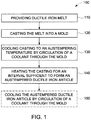
- method 100 After providing 110 a melt of a ductile iron alloy composition 40, method 100 also includes casting 120 the melt into a mold to form a casting 72.
- a melt of the ductile iron alloy 40 can be cast using a faster solidification rate process, which as used herein refers to a process capable of solidifying a melt of a ductile iron alloy at a rate sufficient to obtain a high graphite nodule count.
- suitable rapid solidification processes achieve a graphite nodule count of greater than 100 per square millimeter, more preferably, about 150 to about 300 per square millimeter.
- Such cooling rates are also capable of achieving a refined grain size throughout the casting and reducing the microsegregation of alloying constituents to the intercellular regions or grain boundaries of the casting.
- An acceptable level of microsegregation is indicated by achieving a nodule count above 100 per square millimeter and a matrix that is essentially free of martensite, pearlite, and intercellular carbides in other words, martensite, pearlite and intercellular carbide contents of less than 5 volume percent in the matrix.
- excessive microsegregation at eutectic cell boundaries can be indicated by a low nodule count and high pearlite fractions if the cooling rate to the austempering temperature is insufficient, or by a low nodule count and an excessive martensite content (above 5 volume percent) and a low ausferrite content (below 85 volume percent) in the matrix due to insufficient stabilization of the carbon-enriched austenite during the isothermal austempering.
- Casting 120 may be accomplished using any suitable casting method for casting ductile iron, and more particularly may be cast into any suitable mold 70 as described herein.
- the article may be sand cast as illustrated in FIG. 4 where casting sand 73 is compacted around a fugitive pattern (not shown) that is generally removed by heating, such as by pyrolysis, to define the shape and size of the mold cavity 74, or cast in a permanent or shell mold (not shown) formed from a refractory material and generally surrounded by a compacted casting sand to provide support for the shell, to provide ductile iron article 6.
- Any suitable form of casting 120 may be utilized so long as it is compatible with the cooling 130 and heating 140 by flowing a heat transfer medium through the mold 70 proximate casting 72 as described herein.
- method 100 generally includes cooling 130 the casting 72 from above the upper temperature limit for proeutectoid ferrite (A 3 ) where the microstructure comprises stable austenite to an austempering temperature (T A ) by circulating a suitable coolant through the mold 70.
- the coolant will be selected to obtain a rapid cooling or quench rate in the ductile iron article 6 sufficient to avoid the formation of ferrite or pearlite as illustrated generally in the TTT diagram shown in FIG. 5 .
- Any suitable coolant may be used particularly various coolant fluids that when circulated as a flow (F) have a high heat capacity for removal of heat from the mold 70 and casting 72.
- Coolant fluids will be selected so that the coolant fluid flow (F) into the mold 70 has a temperature that is lower than the austempering temperature so that it is configured to remove heat from the mold 70 and casting 72 and obtain a rapid cooling rate sufficient to avoid the formation of ferrite and/or pearlite and lower the temperature of the casting 72 to the austempering temperature (T A ).
- Suitable fluid coolants include low pressure steam, liquid water, a molten salt or a molten metal, or a combination thereof.
- the austempering temperature (T A ) is above the martensite start temperature (M S ) of the ductile iron alloy to avoid formation of martensite in the casting 72.
- Cooling 130 of casting 72 in the mold 70 is contrasted with conventional cooling of ductile iron articles by quenching the article into a molten salt bath, which requires sufficient molten coolant and a bath that is large enough to accept the ductile iron article, and holding the article during cooling to an austempering temperature and a subsequent austempering heat treatment.
- This process has not been used for very large ductile iron articles, such as, for example, wind turbine rotors. This may be due to the fact that there are very few facilities worldwide that have salt baths of sufficient size to accommodate the such large ductile iron castings or the castings and their molds, and the throughput constraints associated with the cooling and subsequent heat treatment cycles have made this process uneconomical and generally not useful for very large ductile iron articles.
- the method 100 advantageously removes the limitations associated with the sizes of salt bath furnaces used with the direct and in-mold austempering approach described above. Further, the method 100 advantageously reduces or eliminates the need to cool and reheat the castings before performing the austenitization and austempering heat treatments associated with the cool/reheat approach described above thereby reducing cycle time and increasing the efficiency of the casting process compared to conventional ductile iron casting methods.
- the Si level of the ductile iron alloy composition can advantageously be raised to about 4.5 wt.% to further promote formation of graphite nodules without reducing the carbon content of the austenite, which also provides solid solution strengthening of the ausferrite matrix by providing solid solution strengthening of the acicular ferrite.
- the use of high heat capacity coolants described may be employed to provide a finer cell structure, which will also tend to provide enhanced mechanical properties, particularly strength and toughness.
- the mold 70 used for casting 120 has a mold cavity 74 that defines the shape of the casting 72 of the ductile iron article 6, such as main wind turbine shaft 18.
- the mold 70 also includes at least one fluid conduit 76 proximate the mold cavity 74 that is configured to receive the coolant fluid in the case of cooling 130 or cooling 150, or the heating fluid in the case of heating 140, respectively.
- the at least one fluid conduit 76 comprises a plurality of conduits disposed within the mold 70 proximate the mold cavity 74 and configured for thermal communication with the casting 72 and mold 70 for the removal or addition of heat from the casting 72 and mold 70, respectively.
- the mold includes a plurality of fluid conduits 76.
- these may include axially-extending fluid conduits 78.
- these axially-extending fluid conduits 78 may be circumferentially-disposed about the casting 72, that is, they are spaced around the circumference of the casting 72.
- the fluid conduits 76 may also include a plurality of discrete, circumferentially-extending rings 80 that are axially spaced apart along the axis 34 of the casting 72.
- the fluid conduits 76 may also include axially and circumferentially extending rings comprising a coil 82 that is disposed about the mold cavity 74.
- Fluid conduits may be formed of any suitable material that is configured to conduct heat out of (in the case of cooling 130 or cooling 150) or into (in the case of heating 140) the mold 70 and casting 72.
- the fluid conduits 76 may include various metal tubes or pipes, including those formed from various grades of steel, such as various grades of stainless steel, copper alloys and the like.
- one or more mold 70 may be connected to one or more fluid circuit84 for routing the coolant or coolants, or heating fluid or fluids, needed for each mold to and from a centralized heat exchange device 86, or a plurality of devices, where heat may be removed from the coolant(s) or added to the heating fluid flow (F), as the case may be.
- the method 100 also includes heating 140 the casting to maintain the austempering temperature (T A ) for an interval sufficient to form an austempered ductile iron article 8 that comprises a microstructure comprising ausferrite, as described herein.
- Austempering is performed in a temperature range of about 230°C to about 400°C, and the austempering temperature is held for a duration of about one to about four hours.
- Heating 140 is required to maintain the austempering temperature due to the heat loss from the mold 70 and casting 72 that would naturally occur if additional heat is not supplied.
- the importance of the quench method and quench rate should also be noted.
- the equipment used to cool the casting from the austenitization temperature to the austempering temperature can be optimized to promote the kinetics of the austempering process and promote a complete transformation across the entire section thickness, thereby limiting the propensity to form brittle phases.
- the use of the mold 70 employing coolant and heating fluid as described herein preferably promotes a more efficient heat transfer to and from the casting 72 and mold 70 to the heat transfer medium, thereby promoting the cooling 130 and heating 140 necessary to achieve the ausferrite transformation.
- the casting 72 is quenched fast enough during cooling 120 to avoid pearlite formation, such as, for example, at a rate of at least 5.5°C/minute.
- the quench rates needed to do so during cooling 120 will depend in part on the alloy composition, and particularly on how much nickel, molybdenum, copper, etc., are present in the alloy, for example.
- the method 100 may also optionally include cooling 150 the austempered ductile iron article 8 by further circulation of a coolant flow (F) through the mold.
- the coolant used may be one of the same coolants as used above for cooling 130.
- the coolant may be the same coolant employed for cooling 130, or a different coolant.
- the casting 72 can be allowed to cool to room temperature to provide austempered ductile iron articles 8, such as austempered ductile iron wind turbine shaft 18, as described herein.
- the resulting austempered casting 72 is characterized by being through-hardened and having a microstructure made up of a matrix that is substantially, if not entirely, ausferrite and substantially, if not entirely, free of martensite and pearlite and provide the desired mechanical properties for the casting, including hardness, impact strength, tensile strength, fatigue strength and toughness, particularly portions of the ductile iron wind turbine shaft 18 that have high operating stresses, such as the shaft body 38, transition collar 36 or hub flange 30, where higher structural requirements are typically necessary.
- Cooling 150 is advantageous because it may also be performed rapidly and at a controlled cooling rate while the casting 72 is still in the mold and does not require additional facilities or equipment, such as quenching facilities and equipment to cool the casting 72 to room temperature under controlled conditions. Cooling 150 is also an improvement over air cooling of the casting 72, which may not require specialized facilities or equipment, but which has reduced throughput due to the time required to cool large austempered ductile iron articles 8 to room temperature.
- Ductile iron articles 8, including wind turbine shaft 18, produced according to method 100 are capable of exhibiting strength-toughness combinations that can rival low alloy steels, while offering such potential advantages as better wear resistance and better vibration and noise damping, along with the potential for weight reduction and cost savings.
- the machinability of the austempered through-hardened ductile iron articles 8, including wind turbine shafts 18, are likely comparable to a heat treated steel.
- austempered ductile iron articles 8 are also likely to exhibit less distortion compared to a shaft of similar size and design produced by a quench and tempering operation. As a result, the dimensional changes that occur during austempering can be accurately predicted to limit the amount of final machining operations necessary.
Landscapes
- Chemical & Material Sciences (AREA)
- Engineering & Computer Science (AREA)
- Mechanical Engineering (AREA)
- Materials Engineering (AREA)
- Organic Chemistry (AREA)
- Metallurgy (AREA)
- Crystallography & Structural Chemistry (AREA)
- Physics & Mathematics (AREA)
- Thermal Sciences (AREA)
- General Engineering & Computer Science (AREA)
- Ocean & Marine Engineering (AREA)
- Life Sciences & Earth Sciences (AREA)
- Sustainable Development (AREA)
- Sustainable Energy (AREA)
- Combustion & Propulsion (AREA)
- Heat Treatment Of Articles (AREA)
- Molds, Cores, And Manufacturing Methods Thereof (AREA)
- Refinement Of Pig-Iron, Manufacture Of Cast Iron, And Steel Manufacture Other Than In Revolving Furnaces (AREA)
- Wind Motors (AREA)
Description
- A method of making an austempered ductile iron article is disclosed, and more particularly, a method of making large austempered ductile iron articles, and even more particularly, a method of making an austempered ductile iron main shaft of a wind turbine.
- Various alloys have been considered and used to produce large shafts, such as the main shaft of a wind turbine. As an example, forged steel alloys are commonly used for main shafts in wind turbine applications. While forged steel wind turbine shafts are useful, they are generally costly due to their size and the mechanical processing (e.g., forging), heat treating and machining required to obtain the necessary alloy properties.
- Due to their strength, toughness, castability and machinability, ductile iron (cast nodular iron) alloys have also been used to produce wind turbine main shafts. Typical production methods for these shafts have included conventional sand casting, which has generally been employed to produce relatively smaller shafts having wall section thicknesses of less than fifteen centimeters. While this approach has been useful to produce ductile iron wind turbine shafts, the shafts are not well-suited to the demanding service requirements of more recent wind turbine designs, which include larger sizes, including higher casting weights, larger diameters and larger shaft wall section thicknesses. As larger main shafts become required for wind turbine applications, their design requirements for strength and toughness have exceeded the capability of conventional cast ductile iron alloys, and methods that enable the manufacture of ductile iron wind turbine main shafts having larger sizes, including higher casting weights, larger diameters and larger shaft wall section thicknesses are very desirable.
-
US 4,222,429 A relates to a tempering process in a fluidizable sand bed. -
EP 2 322 678 A1 andWO 2008/076051 A1 disclose methods of making austempered ductile iron articles via the conventional methods. - Therefore, improved methods of making ductile iron articles, particularly large ductile iron articles, such as the main shafts of wind turbines, are very desirable.
- According to one aspect, the invention resides in a method of making an austempered ductile iron article as defined in claim 1.
- These and other advantages and features will become more apparent from the following description taken in conjunction with the drawings.
- Embodiments of the present invention will now be described, by way of example only, with reference to the accompanying drawings in which:
-
FIG. 1 is a flow chart of an exemplary embodiment of a method of making an austempered ductile iron article as disclosed herein; -
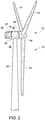
FIG. 2 is a schematic perspective view of an exemplary embodiment of a wind turbine as disclosed herein; -
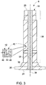
FIG. 3 is a schematic cross-sectional view of an exemplary embodiment of the main turbine shaft of the wind turbine ofFIG. 2 ; -
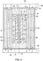
FIG. 4 is a schematic cross-sectional view of an exemplary embodiment of a mold and casting as disclosed herein; and -
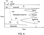
FIG. 5 is a schematic illustration of a time-temperature-transformation (TTT) diagram of a ductile iron alloy composition having a thermal profile of a method as disclosed herein superimposed thereon. - The detailed description explains embodiments of the invention, together with advantages and features, by way of example with reference to the drawings.
- Referring to
FIGS. 1-5 , an exemplary embodiment of a method 100 (FIG. 1 ) of making an austemperedductile iron article 8 is disclosed. The method includes providing 110 a melt of a ductile iron alloy composition. The method also includes casting 120 the melt into amold 70 to form a casting 72 (FIG. 4 ). The method further includes cooling 130 thecasting 72 to an austempering temperature by circulating a coolant through themold 70, wherein cooling comprises solidifying the melt and forming aductile iron article 6. Still further, the method includes heating 140 thecasting 72 to maintain the austempering temperature for an interval sufficient to form an austemperedductile iron article 8. Optionally, themethod 100 also may include cooling 150 the austemperedductile iron article 8 after heating 140 by circulation of a coolant through themold 70. - In certain embodiments, the use of the
method 100 advantageously enables reduction or elimination of cooling and reheating of castings prior to performing the austempering heat treatment. In addition, when using themethod 100 the size of the casting may be increased because the austempering heat treatment is no longer limited by the size of the salt bath furnaces typically used to perform the austempering heat treatment, whether by direct immersion of the ductile iron article or the article in its mold. Thus, themethod 100 is particularly useful for making very largeductile iron articles 8, such aswind turbine shafts 18, where the article may weigh several tons or more, and have wall-section thicknesses that are very thick, including sections that are 100 mm thick or more. Another advantage realized using themethod 100 is that the amount of Si can be raised up to about 4.5 wt% without reducing the carbon content in the austenite, which also provides solid solution strengthening of the ausferrite matrix. The use of low pressure steam or water as a coolant provides a finer cell structure, which leads to enhanced mechanical properties. Themethod 100 promotes rapid heat transfer with respect to both heating and cooling, thereby reducing cycle time and increasing the efficiency of the austempering heat treatment. - Referring to
FIGS. 1-5 , themethod 100 may be used to make any suitable austemperedductile iron article 8, but is particularly well-suited to making large austempered articles, such as wind turbinemain shafts 18 having a weight of about 2 to about 20 tons or more, and more particularly those having wall-section thicknesses of about 100 to about 200 mm or more. The austemperedductile iron articles 8 are made from appropriately sized castductile iron articles 6 that are formed by casting and austempered to provide austemperedductile iron articles 8 that advantageously have a hardness, strength and toughness that are higher than the precursor castductile iron articles 6. Themethod 100 may be used to make any suitableductile iron article 8, but is particularly useful for making various large wind turbine components, and more particularly, for making large ductile ironwind turbine shafts 18.Wind turbine shafts 18 are essential components of awind turbine 10. Whilewind turbine shafts 18 are essential wind turbine components, they generally have not been made from ductile cast iron owing to the fact that it has not been possible to obtain the ductility, strength, toughness and fatigue resistance required, particularly for largewind turbine shafts 18. The use ofmethod 100 enables the manufacture of austempered ductile ironwind turbine shafts 18, and particularly the manufacture of large austempered ductile iron wind turbine shafts, as well as other large austemperedductile iron articles 8 forwind turbines 10 and other applications. -
Wind turbine 10 generally includes arotor blade assembly 12 comprisingmultiple blades 14 radially extending from ahub 16. Thehub 16 is mounted on a rotatable austempered ductile iron wind turbine shaft 18 (FIGS. 2 and3 ), which forms part of a drive train that includes agearbox 24 connected to anelectric generator 25. The austempered ductile ironwind turbine shaft 18, drive train andelectric generator 25 are all housed within anacelle 20 mounted on atower 22. The rotatable austempered ductile ironwind turbine shaft 18 includes ahub end 26 and anopposed gearbox end 28. Thehub end 26 includes anintegral hub flange 30 that is formed on thehub end 26 and is configured for coupling and attachment to thehub 16. Thegearbox end 28 is configured for coupling and attachment to thegearbox 24. The austempered ductile ironwind turbine shaft 18 generally includes ashaft bore 32 that extends along thelongitudinal axis 34. The austempered ductile ironwind turbine shaft 18 also may include atransition collar 36 that smooths the transition from the outer portion of theshaft body 38 to thehub flange 30. Depending on the size of theturbine 10, the main austempered ductile ironwind turbine shaft 18 may be quite large, including those having a weight and wall-section thickness as described herein and lengths of about 2 m to about 4 m or more, main flange diameters of about 1 m to about 2 m or more and shaft bores of about 0.4 to about 0.8 m or more. Because themain shaft 18 must operate in cold weather and withstand a significant amount of torque of about 4000 to about 15,000 kNm and a bending moment of about 7,000 to about 15,000 kNm induced by the action of wind on theblades 14, the austempered ductile ironwind turbine shaft 18 is advantageous in that it provides a balance of strength and toughness sufficient to withstand these torques and bending moments. - As illustrated schematically in an exemplary embodiment in
FIG. 3 , the austempered ductile ironwind turbine shaft 18 made by themethod 100 described herein may be described as having anaustempered microstructure 40 comprising anausferrite matrix 42 and a plurality ofgraphite nodules 44 dispersed in theausferrite matrix 42. Theausferrite matrix 42 includes a carbon-stabilizedaustenite matrix 46 andacicular ferrite 48. Forming the ausferrite by austempering in accordance with themethod 100 forms greatly increases hardness, impact strength, tensile strength and low cycle fatigue strength of theductile iron article 8, including ductile ironwind turbine shaft 18. - Providing 110 of a ductile iron melt may be performed in any suitable manner. A ductile iron alloy composition may, for example, be melted in a special type of blast furnace known as a cupola, but may also be melted in various electric induction furnaces. After melting is complete, the molten ductile iron alloy composition is generally poured into a holding furnace or ladle. The molten ductile iron alloy composition may be formed by re-melting pig iron, often along with substantial quantities of scrap iron and scrap steel and taking various steps to remove undesirable contaminants. Depending on the application, the carbon and silicon content may be adjusted to the desired levels. Other alloying elements may then be added to the melt before the final form is produced by casting. A wide variety of ductile iron alloy compositions and
ductile iron articles 6 may be provided in accordance withmethod 100 as disclosed herein, includingwind turbine shaft 18. The ductile iron alloy compositions may contain typical alloying constituents for ductile iron, for example, carbon, silicon and manganese and optionally copper, nickel and/or molybdenum, with the balance iron and incidental impurities such as chromium, phosphorus, sulfur, etc. In one embodiment, the ductile iron alloy composition comprises, by weight of the alloy, about 3.0 to about 4.5 percent silicon, about 2.0 to about 3.0 percent nickel, up to about 0.2 percent manganese, up to about 0.03 percent chromium, up to about 0.01 percent vanadium, and the balance iron and incidental impurities. More particularly, this ductile iron alloy composition may include about 0.001 to about 0.2 percent manganese, about 0.001 to about 0.03 percent chromium, and about 0.001 to about 0.01 percent vanadium. The alloys may also optionally include up to about 0.3% molybdenum and up to about 0.8% copper. As known in the art, the level for carbon is necessary for graphite formation and castability considerations. The role of silicon is generally to promote the formation of graphite instead of metastable iron carbide during solidification. The carbon content separates as spheroidal graphite during solidification, primarily as the result of the presence of silicon. The spheroidal graphite imparts such desirable properties as high strength and toughness for which ductile iron alloys are known. Molybdenum can be included to increase ausferrite hardenability and retard pearlite formation in austempered ductile irons. Manganese can be included to scavenge sulfur, which is preferably absent from the alloy but is usually unavoidably present as an impurity. For castings having a relatively thick section, such as the mainwind turbine shaft 18, phosphorus is considered detrimental because it counteracts the effects of molybdenum. Therefore, phosphorous levels are preferably kept at levels as low as possible, for example, below 0.1 weight percent. Also in heavy section castings such as thewind turbine shaft 18, relatively high levels of copper, nickel and molybdenum may be necessary for ausferrite hardenability considerations, for example, toward the upper ends of their above-stated ranges. Generally, preferred alloy additions and their relative amounts can be balanced to achieve sufficient hardenability for a given section size, while reducing alloy segregation levels and cost. - After providing 110 a melt of a ductile
iron alloy composition 40,method 100 also includes casting 120 the melt into a mold to form a casting 72. In order to obtain a desirable refined grain microstructure, high graphite nodule count and minimal microsegregation of the alloying constituents to grain boundaries and resultant porosity, a melt of theductile iron alloy 40 can be cast using a faster solidification rate process, which as used herein refers to a process capable of solidifying a melt of a ductile iron alloy at a rate sufficient to obtain a high graphite nodule count. As an example, suitable rapid solidification processes achieve a graphite nodule count of greater than 100 per square millimeter, more preferably, about 150 to about 300 per square millimeter. Such cooling rates are also capable of achieving a refined grain size throughout the casting and reducing the microsegregation of alloying constituents to the intercellular regions or grain boundaries of the casting. An acceptable level of microsegregation is indicated by achieving a nodule count above 100 per square millimeter and a matrix that is essentially free of martensite, pearlite, and intercellular carbides in other words, martensite, pearlite and intercellular carbide contents of less than 5 volume percent in the matrix. On the other hand, excessive microsegregation at eutectic cell boundaries can be indicated by a low nodule count and high pearlite fractions if the cooling rate to the austempering temperature is insufficient, or by a low nodule count and an excessive martensite content (above 5 volume percent) and a low ausferrite content (below 85 volume percent) in the matrix due to insufficient stabilization of the carbon-enriched austenite during the isothermal austempering. - Casting 120 may be accomplished using any suitable casting method for casting ductile iron, and more particularly may be cast into any
suitable mold 70 as described herein. In one exemplary embodiment, the article may be sand cast as illustrated inFIG. 4 where castingsand 73 is compacted around a fugitive pattern (not shown) that is generally removed by heating, such as by pyrolysis, to define the shape and size of themold cavity 74, or cast in a permanent or shell mold (not shown) formed from a refractory material and generally surrounded by a compacted casting sand to provide support for the shell, to provideductile iron article 6. Any suitable form of casting 120 may be utilized so long as it is compatible with the cooling 130 andheating 140 by flowing a heat transfer medium through themold 70proximate casting 72 as described herein. - In the various embodiments,
method 100 generally includes cooling 130 the casting 72 from above the upper temperature limit for proeutectoid ferrite (A3) where the microstructure comprises stable austenite to an austempering temperature (TA) by circulating a suitable coolant through themold 70. The coolant will be selected to obtain a rapid cooling or quench rate in theductile iron article 6 sufficient to avoid the formation of ferrite or pearlite as illustrated generally in the TTT diagram shown inFIG. 5 . Any suitable coolant may be used particularly various coolant fluids that when circulated as a flow (F) have a high heat capacity for removal of heat from themold 70 and casting 72. Coolant fluids will be selected so that the coolant fluid flow (F) into themold 70 has a temperature that is lower than the austempering temperature so that it is configured to remove heat from themold 70 and casting 72 and obtain a rapid cooling rate sufficient to avoid the formation of ferrite and/or pearlite and lower the temperature of the casting 72 to the austempering temperature (TA). Suitable fluid coolants include low pressure steam, liquid water, a molten salt or a molten metal, or a combination thereof. As known in the art, the austempering temperature (TA) is above the martensite start temperature (MS) of the ductile iron alloy to avoid formation of martensite in the casting 72. Cooling 130 of casting 72 in themold 70 is contrasted with conventional cooling of ductile iron articles by quenching the article into a molten salt bath, which requires sufficient molten coolant and a bath that is large enough to accept the ductile iron article, and holding the article during cooling to an austempering temperature and a subsequent austempering heat treatment. This process has not been used for very large ductile iron articles, such as, for example, wind turbine rotors. This may be due to the fact that there are very few facilities worldwide that have salt baths of sufficient size to accommodate the such large ductile iron castings or the castings and their molds, and the throughput constraints associated with the cooling and subsequent heat treatment cycles have made this process uneconomical and generally not useful for very large ductile iron articles. Other conventional alternatives to the process described including cooling the cast ductile iron article to room temperature followed by a subsequent reheat to an austenitizing temperature followed by an austempering heat treatment. This process has also not been used for very large ductile iron articles, such as, for example, wind turbine rotors. This may also be due to the fact that there are very few facilities worldwide that have salt baths or furnaces of sufficient size to accommodate such large ductile iron castings for reheating. This fact, coupled with fact that the throughput constraints associated with the subsequent reheat cycles for articles having such large thermal mass, may have made this process uneconomical and generally not useful for very large ductile iron articles, particularly wind turbine shafts. Thus, themethod 100 advantageously removes the limitations associated with the sizes of salt bath furnaces used with the direct and in-mold austempering approach described above. Further, themethod 100 advantageously reduces or eliminates the need to cool and reheat the castings before performing the austenitization and austempering heat treatments associated with the cool/reheat approach described above thereby reducing cycle time and increasing the efficiency of the casting process compared to conventional ductile iron casting methods. In addition, as described, the Si level of the ductile iron alloy composition can advantageously be raised to about 4.5 wt.% to further promote formation of graphite nodules without reducing the carbon content of the austenite, which also provides solid solution strengthening of the ausferrite matrix by providing solid solution strengthening of the acicular ferrite. Further, the use of high heat capacity coolants described may be employed to provide a finer cell structure, which will also tend to provide enhanced mechanical properties, particularly strength and toughness. - The
mold 70 used for casting 120 has amold cavity 74 that defines the shape of the casting 72 of theductile iron article 6, such as mainwind turbine shaft 18. Themold 70 also includes at least onefluid conduit 76 proximate themold cavity 74 that is configured to receive the coolant fluid in the case of cooling 130 or cooling 150, or the heating fluid in the case ofheating 140, respectively. In one embodiment, the at least onefluid conduit 76 comprises a plurality of conduits disposed within themold 70 proximate themold cavity 74 and configured for thermal communication with the casting 72 andmold 70 for the removal or addition of heat from the casting 72 andmold 70, respectively. In one embodiment, as illustrated inFIG. 4 , the mold includes a plurality offluid conduits 76. These may include axially-extending fluid conduits 78. In one embodiment as shown inFIG. 4 , these axially-extending fluid conduits 78 may be circumferentially-disposed about the casting 72, that is, they are spaced around the circumference of the casting 72. In another embodiment, as also illustrated inFIG. 4 , thefluid conduits 76 may also include a plurality of discrete, circumferentially-extendingrings 80 that are axially spaced apart along theaxis 34 of the casting 72. In yet another embodiment, as also illustrated inFIG. 4 , thefluid conduits 76 may also include axially and circumferentially extending rings comprising acoil 82 that is disposed about themold cavity 74. Fluid conduits may be formed of any suitable material that is configured to conduct heat out of (in the case of cooling 130 or cooling 150) or into (in the case of heating 140) themold 70 and casting 72. In one embodiment, thefluid conduits 76 may include various metal tubes or pipes, including those formed from various grades of steel, such as various grades of stainless steel, copper alloys and the like. Advantageously, one ormore mold 70 may be connected to one or more fluid circuit84 for routing the coolant or coolants, or heating fluid or fluids, needed for each mold to and from a centralizedheat exchange device 86, or a plurality of devices, where heat may be removed from the coolant(s) or added to the heating fluid flow (F), as the case may be. This allowsmany molds 70 andcastings 72 to have their temperatures regulated from one or more centralized source, or from various distributed sources, but does not require individual furnaces for heat treatment as is typical for conventional austempering heat treatment processes. This is particularly advantageous due to the size of the furnaces needed to heat treat very large ductile iron articles and the costs associated with building, maintaining and operating them that may be avoided by the use ofmethod 100. - After cooling 130, the
method 100 also includesheating 140 the casting to maintain the austempering temperature (TA) for an interval sufficient to form an austemperedductile iron article 8 that comprises a microstructure comprising ausferrite, as described herein. Austempering is performed in a temperature range of about 230°C to about 400°C, and the austempering temperature is held for a duration of about one to about four hours.Heating 140 is required to maintain the austempering temperature due to the heat loss from themold 70 and casting 72 that would naturally occur if additional heat is not supplied. At the austempering temperature, the casting undergoes an ausferrite transformation in which the parent face centered cubic crystal lattice austenite is transformed to ausferrite which comprises acicular ferrite in a high carbon stabilized austenite matrix. In general, a high austempering temperature will tend to promote greater fatigue strength and ductility, while a low austempering temperature will tend to promote greater strength and wear resistance. Accordingly, the austempering temperature can be chosen to promote certain properties of the ductile ironwind turbine shaft 18, depending on its particular requirements. - In the various embodiments,
method 100 andheating 140 generally includes heating the casting 72 to achieve or maintain an austempering temperature (TA) by circulating a flow (F) of suitable heating fluid through themold 70. Any suitable heating fluid may be used. The heating fluid will be selected to obtain a heating rate in theductile iron article 6 sufficient to maintain the austempering temperature as illustrated generally in the TTT diagram shown inFIG. 5 . Any suitable heat transfer medium may be used, including heating fluids that have a high heat capacity for the addition of heat to themold 70 and casting 72. Heating fluids will be selected so that the heating fluid flowing into themold 70 has a temperature that is greater than or equal to the austempering temperature so that it is configured to add heat to themold 70 and casting 72 and obtain a rapid heating rate sufficient to maintain the transformation to ausferrite and maintain the austempering temperature (TA). Suitable heating fluids include high pressure steam, a molten salt or a molten metal, or a combination thereof. As known in the art, the austempering temperature is above the martensite start temperature of the ductile iron alloy to avoid formation of martensite in the casting as shown inFIG. 5 . - The importance of the quench method and quench rate should also be noted. The equipment used to cool the casting from the austenitization temperature to the austempering temperature can be optimized to promote the kinetics of the austempering process and promote a complete transformation across the entire section thickness, thereby limiting the propensity to form brittle phases. In particular, the use of the
mold 70 employing coolant and heating fluid as described herein preferably promotes a more efficient heat transfer to and from the casting 72 andmold 70 to the heat transfer medium, thereby promoting the cooling 130 andheating 140 necessary to achieve the ausferrite transformation. This may promote faster reaction kinetics than those achievable with conventional processes and enable transforming a given wall-section thickness more rapidly, or enable transforming a given wall-section to a deeper depth, as compared to a similarductile iron article 6 heat treated with conventional processes. Such modifications and alternatives may also be able to compensate for shortcomings of the casting process that resulted in one or more of the preferred characteristics (refined grain microstructure, high graphite nodule count, and minimal microsegregation) being incompletely met. In any event, the casting 72 is quenched fast enough during cooling 120 to avoid pearlite formation, such as, for example, at a rate of at least 5.5°C/minute. The quench rates needed to do so during cooling 120 will depend in part on the alloy composition, and particularly on how much nickel, molybdenum, copper, etc., are present in the alloy, for example. - Following
heating 140 and the austempering soak, themethod 100 may also optionally include cooling 150 the austemperedductile iron article 8 by further circulation of a coolant flow (F) through the mold. The coolant used may be one of the same coolants as used above for cooling 130. The coolant may be the same coolant employed for cooling 130, or a different coolant. The casting 72 can be allowed to cool to room temperature to provide austemperedductile iron articles 8, such as austempered ductile ironwind turbine shaft 18, as described herein. The resulting austempered casting 72 is characterized by being through-hardened and having a microstructure made up of a matrix that is substantially, if not entirely, ausferrite and substantially, if not entirely, free of martensite and pearlite and provide the desired mechanical properties for the casting, including hardness, impact strength, tensile strength, fatigue strength and toughness, particularly portions of the ductile ironwind turbine shaft 18 that have high operating stresses, such as theshaft body 38,transition collar 36 orhub flange 30, where higher structural requirements are typically necessary. Cooling 150 is advantageous because it may also be performed rapidly and at a controlled cooling rate while the casting 72 is still in the mold and does not require additional facilities or equipment, such as quenching facilities and equipment to cool the casting 72 to room temperature under controlled conditions. Cooling 150 is also an improvement over air cooling of the casting 72, which may not require specialized facilities or equipment, but which has reduced throughput due to the time required to cool large austemperedductile iron articles 8 to room temperature. -
Ductile iron articles 8, includingwind turbine shaft 18, produced according tomethod 100 are capable of exhibiting strength-toughness combinations that can rival low alloy steels, while offering such potential advantages as better wear resistance and better vibration and noise damping, along with the potential for weight reduction and cost savings. The machinability of the austempered through-hardenedductile iron articles 8, includingwind turbine shafts 18, are likely comparable to a heat treated steel. However, austemperedductile iron articles 8 are also likely to exhibit less distortion compared to a shaft of similar size and design produced by a quench and tempering operation. As a result, the dimensional changes that occur during austempering can be accurately predicted to limit the amount of final machining operations necessary. - The terms "a" and "an" herein do not denote a limitation of quantity, but rather denote the presence of at least one of the referenced items. The modifier "about" used in connection with a quantity is inclusive of the stated value and has the meaning dictated by the context (e.g., includes the degree of error associated with measurement of the particular quantity). Furthermore, unless otherwise limited all ranges disclosed herein are inclusive and combinable (e.g., ranges of "up to about 25 weight percent (wt.%), more particularly about 5 wt.% to about 20 wt.% and even more particularly about 10 wt.% to about 15 wt.%" are inclusive of the endpoints and all intermediate values of the ranges, e.g., "about 5 wt.% to about 25 wt.%, about 5 wt.% to about 15 wt.%", etc.). The use of "about" in conjunction with a listing of constituents of an alloy composition is applied to all of the listed constituents, and in conjunction with a range to both endpoints of the range. Finally, unless defined otherwise, technical and scientific terms used herein have the same meaning as is commonly understood by one of skill in the art to which this invention belongs. The suffix "(s)" as used herein is intended to include both the singular and the plural of the term that it modifies, thereby including one or more of that term (e.g., the metal(s) includes one or more metals). Reference throughout the specification to "one embodiment", "another embodiment", "an embodiment", and so forth, means that a particular element (e.g., feature, structure, and/or characteristic) described in connection with the embodiment is included in at least one embodiment described herein, and may or may not be present in other embodiments.
- It is to be understood that the use of "comprising" in conjunction with the alloy compositions described herein specifically discloses and includes the embodiments wherein the alloy compositions "consist essentially of' the named components (i.e., contain the named components and no other components that significantly adversely affect the basic and novel features disclosed), and embodiments wherein the alloy compositions "consist of' the named components (i.e., contain only the named components except for contaminants which are naturally and inevitably present in each of the named components).
- While the invention has been described in detail in connection with only a limited number of embodiments, it should be readily understood that the invention is not limited to such disclosed embodiments. Rather, the invention can be modified to incorporate any number of variations, alterations, substitutions or equivalent arrangements not heretofore described, but which are within the scope of the invention as set forth in the appended claims. Additionally, while various embodiments of the invention have been described, it is to be understood that aspects of the invention may include only some of the described embodiments. Accordingly, the invention is not to be seen as limited by the foregoing description, but is only limited by the scope of the appended claims.
Claims (15)
- A method of making an austempered ductile iron article (6), comprising:providing (110) a melt of a ductile iron alloy composition (40);casting the melt (120) into a mold (70) to form a casting (72);cooling (130) the casting (72) to an austempering temperature (TA) from 230°C to 400°C by circulating a coolant through the mold (70); wherein cooling comprises solidifying the melt and forming a ductile iron article (6); andheating (140) the casting (72) to maintain the austempering temperature (TA) for an interval of one to four hours sufficient to form an austempered ductile iron article (6) that comprises a microstructure comprising ausferrite.
- The method of claim 1, further comprising cooling (150) the austempered ductile iron article (6) after heating by circulation of a coolant through the mold (70).
- The method of any of claims 1 or 2, wherein the ductile iron alloy composition (40) comprises, by weight of the alloy: 3.0 to 4.5 percent silicon, 2.0 to 3.0 percent nickel, up to 0.2 percent manganese, up to 0.03 percent chromium, up to 0.01 percent vanadium, and the balance iron and incidental impurities.
- The method of claim 3, wherein the ductile iron alloy composition (40) comprises 0.001 to 0.2 percent manganese, 0.001 to 0.03 percent chromium, and 0.001 to 0.01 percent vanadium.
- The method of any of claims 3 or 4, wherein the ductile iron alloy composition (40) is selected to comprise 4.5% silicon so that the as-cooled microstructure comprises solid solution strengthened ausferrite.
- The method of any preceding claim, wherein circulating the coolant to form the ductile iron article (6) and/or the austempered ductile iron article (6) comprises circulating a coolant fluid through the mold (70), wherein the coolant fluid is configured to remove heat from the ductile iron article (6).
- The method of claim 6, wherein the coolant fluid has a temperature lower than the austempering temperature (TA).
- The method of claim 6 or 7, wherein the coolant fluid comprises low pressure steam, liquid water, a molten salt or a molten metal, or a combination thereof.
- The method of any preceding claim, wherein heating comprises circulating a heating fluid through the mold (70), wherein the heating fluid is configured to provide heat to the ductile iron article (6).
- The method of claim 9, wherein the heating fluid comprises a high pressure steam, a molten salt or a metal, or a combination thereof.
- The method of claim 9 or 10, wherein the heating fluid has a temperature greater than or equal to the austempering temperature.
- The method of claim 6 or 9, wherein at least one of circulating the coolant or circulating the heating fluid is performed by providing a fluid conduit (76) within the mold (70) proximate a mold cavity (74) that is configured to receive the coolant or the heating fluid, respectively.
- The method of claim 12, wherein the fluid conduit (76) comprises a plurality of fluid conduits.
- The method of claim 12 or 13, wherein the mold (70) has a longitudinal axis and the conduit comprises one of an axially-extending conduit (76) or a circumferentially extending conduit (76).
- The method of any preceding claim, wherein the austempered ductile iron article (6) comprises a wind turbine shaft.
Priority Applications (1)
| Application Number | Priority Date | Filing Date | Title |
|---|---|---|---|
| PL12198564T PL2612930T3 (en) | 2012-01-03 | 2012-12-20 | Method of making an austempered ductile iron adi article |
Applications Claiming Priority (1)
| Application Number | Priority Date | Filing Date | Title |
|---|---|---|---|
| US13/342,711 US8524016B2 (en) | 2012-01-03 | 2012-01-03 | Method of making an austempered ductile iron article |
Publications (3)
| Publication Number | Publication Date |
|---|---|
| EP2612930A2 EP2612930A2 (en) | 2013-07-10 |
| EP2612930A3 EP2612930A3 (en) | 2017-07-19 |
| EP2612930B1 true EP2612930B1 (en) | 2020-06-17 |
Family
ID=47435806
Family Applications (1)
| Application Number | Title | Priority Date | Filing Date |
|---|---|---|---|
| EP12198564.2A Active EP2612930B1 (en) | 2012-01-03 | 2012-12-20 | Method of making an austempered ductile iron adi article |
Country Status (4)
| Country | Link |
|---|---|
| US (1) | US8524016B2 (en) |
| EP (1) | EP2612930B1 (en) |
| JP (1) | JP6205126B2 (en) |
| PL (1) | PL2612930T3 (en) |
Families Citing this family (10)
| Publication number | Priority date | Publication date | Assignee | Title |
|---|---|---|---|---|
| CN105081228A (en) * | 2014-05-19 | 2015-11-25 | 长沙酉诚凸轮轴制造有限公司 | Casting process for high-strength and low-alloy chilling spheroidal graphite cast iron camshaft blanks |
| CN104331549B (en) * | 2014-10-27 | 2017-06-16 | 扬州大学 | The Optimization Design of the austempered ductile iron alloying component calculated based on Jmatpro material properties |
| EP3088537A1 (en) * | 2015-04-27 | 2016-11-02 | Georg Fischer GmbH | Production method for hpi cast iron |
| CN107653412A (en) * | 2017-08-23 | 2018-02-02 | 安徽东星汽车部件有限公司 | A kind of wear resistant automobile stamping part die material |
| CN107723458B (en) * | 2017-11-17 | 2018-12-25 | 湖南大学 | Heat treatment can reinforced aluminium alloy ag(e)ing process on-line monitoring method |
| CN108754302B (en) * | 2018-08-14 | 2019-10-18 | 北京工业大学 | A kind of high-ductility high wear-resistant carbide-containing austempering ductile iron and preparation method thereof |
| SE545732C2 (en) * | 2019-02-08 | 2023-12-27 | Ausferritic Ab | Method for producing ausferritic steel and ductile iron, austempered in rapid cycles followed by baking |
| CN113118381B (en) * | 2021-04-11 | 2023-07-07 | 陕西柴油机重工有限公司 | Method for molding large-section nodular cast iron shielding hemispherical casting |
| CN113462955B (en) * | 2021-06-30 | 2022-05-03 | 东风商用车有限公司 | High-strength high-toughness isothermal quenching ductile iron material and preparation method and application thereof |
| CN117488030B (en) * | 2023-12-21 | 2024-03-19 | 盐城市鑫纬嘉新能源科技有限公司 | Ductile iron isothermal quenching cooling device |
Citations (2)
| Publication number | Priority date | Publication date | Assignee | Title |
|---|---|---|---|---|
| WO2008076051A1 (en) * | 2006-12-16 | 2008-06-26 | Indexator Ab | Austempered ductile iron, method for producin this and component comprising this iron |
| EP2322678A1 (en) * | 2009-07-23 | 2011-05-18 | General Electric Company | Heavy austempered ductile iron components |
Family Cites Families (13)
| Publication number | Priority date | Publication date | Assignee | Title |
|---|---|---|---|---|
| US3615880A (en) * | 1968-04-03 | 1971-10-26 | Gen Electric | Ferrous metal die casting process and products |
| US4157111A (en) * | 1976-01-06 | 1979-06-05 | Kubota, Ltd. | Method of heat-treating ductile cast iron pipe |
| US4222429A (en) * | 1979-06-05 | 1980-09-16 | Foundry Management, Inc. | Foundry process including heat treating of produced castings in formation sand |
| FR2522291A1 (en) * | 1982-03-01 | 1983-09-02 | Pont A Mousson | CENTRIFUGAL CAST IRON WITH SPHEROIDAL GRAPHITE AND MANUFACTURING METHOD THEREOF |
| JPS60221525A (en) * | 1984-04-18 | 1985-11-06 | Kubota Ltd | Manufacture of ductile cast iron pipe with high strength |
| JPS62148067A (en) * | 1985-12-24 | 1987-07-02 | Kubota Ltd | Production of high strength ductile cast iron tube |
| JPH01157760A (en) * | 1987-12-16 | 1989-06-21 | Toshiba Mach Co Ltd | Method for cooling and heating die |
| US4880477A (en) | 1988-06-14 | 1989-11-14 | Textron, Inc. | Process of making an austempered ductile iron article |
| US5028281A (en) | 1988-06-14 | 1991-07-02 | Textron, Inc. | Camshaft |
| US5139579A (en) | 1990-04-27 | 1992-08-18 | Applied Process | Method for preparing high silicon, low carbon austempered cast iron |
| US5327955A (en) * | 1993-05-04 | 1994-07-12 | The Board Of Trustees Of Western Michigan University | Process for combined casting and heat treatment |
| JP3163561B2 (en) * | 1994-01-20 | 2001-05-08 | 川崎製鉄株式会社 | Manufacturing method of composite roll |
| SE513287C2 (en) * | 1998-11-06 | 2000-08-21 | Volvo Lastvagnar Ab | Method and apparatus for mold casting |
-
2012
- 2012-01-03 US US13/342,711 patent/US8524016B2/en active Active
- 2012-12-13 JP JP2012271854A patent/JP6205126B2/en not_active Expired - Fee Related
- 2012-12-20 PL PL12198564T patent/PL2612930T3/en unknown
- 2012-12-20 EP EP12198564.2A patent/EP2612930B1/en active Active
Patent Citations (2)
| Publication number | Priority date | Publication date | Assignee | Title |
|---|---|---|---|---|
| WO2008076051A1 (en) * | 2006-12-16 | 2008-06-26 | Indexator Ab | Austempered ductile iron, method for producin this and component comprising this iron |
| EP2322678A1 (en) * | 2009-07-23 | 2011-05-18 | General Electric Company | Heavy austempered ductile iron components |
Also Published As
| Publication number | Publication date |
|---|---|
| EP2612930A2 (en) | 2013-07-10 |
| US8524016B2 (en) | 2013-09-03 |
| US20130167984A1 (en) | 2013-07-04 |
| JP2013144313A (en) | 2013-07-25 |
| PL2612930T3 (en) | 2020-12-14 |
| JP6205126B2 (en) | 2017-09-27 |
| EP2612930A3 (en) | 2017-07-19 |
Similar Documents
| Publication | Publication Date | Title |
|---|---|---|
| EP2612930B1 (en) | Method of making an austempered ductile iron adi article | |
| CN100485075C (en) | High-carbon high-vanadium high-speed steel composite roller and heat treatment method thereof | |
| CN105618715B (en) | A kind of wear-resistant high speed steel composite roll and preparation method thereof | |
| CN103624084B (en) | Resource-saving type high-boron high-speed steel composite roll and manufacturing method thereof | |
| EP2465952A1 (en) | Method of producing large components form austempered ductile iron alloys | |
| CN104148399B (en) | For abrasion-resistant roller of mill stand and preparation method thereof in steel rolling | |
| CN102242316B (en) | H13 die steel and preparation method thereof | |
| CN101302599A (en) | Niobium microalloyed high strength hot work die steel and preparation thereof | |
| CN103540855A (en) | High-toughness high-boron medium-chrome low-carbon wear-resisting alloy steel and preparation method thereof | |
| CN103556064A (en) | Metastable austenite high-boron high-chrome low-carbon wear-resisting alloy steel and preparation method thereof | |
| CN103866200A (en) | High-boron high-speed steel combined roller and manufacturing method thereof | |
| JP2011026705A (en) | Large size component of austempered spheroidal graphite cast iron | |
| CN104264043A (en) | Wear-resisting and high-speed centrifugally cast steel composite roll and preparation method thereof | |
| EP2302089A1 (en) | Steam turbine rotor and alloy therefor | |
| CN110964973B (en) | High-manganese CADI and heat treatment method thereof | |
| CN102864383B (en) | Low alloy steel | |
| CN1067443C (en) | Multi-element w-alloy cast iron roll collar and its making technology | |
| JP5200164B2 (en) | Semi-finished products and methods | |
| CN103215526B (en) | Centrifugally-cast high-carbon high-alloy steel and heat treatment method thereof | |
| CN105463302B (en) | A kind of preparation method of high rigidity spheroidal graphite cast-iron tup | |
| CN116334483A (en) | Reducing roller collar based on steel tube rolling mill and manufacturing method thereof | |
| CN104651731B (en) | A kind of large-size ball mill liner plate and preparation method thereof | |
| US8968497B2 (en) | Methods of forming and austempering a ductile iron article and article made thereby | |
| CN105483510B (en) | A kind of preparation method of impact resistance spheroidal graphite cast-iron tup | |
| CN103225036B (en) | A kind of boron-carbide reinforced wear-resistant bainite ductile iron abrading-ball and manufacture method thereof |
Legal Events
| Date | Code | Title | Description |
|---|---|---|---|
| PUAI | Public reference made under article 153(3) epc to a published international application that has entered the european phase |
Free format text: ORIGINAL CODE: 0009012 |
|
| AK | Designated contracting states |
Kind code of ref document: A2 Designated state(s): AL AT BE BG CH CY CZ DE DK EE ES FI FR GB GR HR HU IE IS IT LI LT LU LV MC MK MT NL NO PL PT RO RS SE SI SK SM TR |
|
| AX | Request for extension of the european patent |
Extension state: BA ME |
|
| PUAL | Search report despatched |
Free format text: ORIGINAL CODE: 0009013 |
|
| AK | Designated contracting states |
Kind code of ref document: A3 Designated state(s): AL AT BE BG CH CY CZ DE DK EE ES FI FR GB GR HR HU IE IS IT LI LT LU LV MC MK MT NL NO PL PT RO RS SE SI SK SM TR |
|
| AX | Request for extension of the european patent |
Extension state: BA ME |
|
| RIC1 | Information provided on ipc code assigned before grant |
Ipc: B22C 23/00 20060101ALI20170613BHEP Ipc: C21D 5/00 20060101AFI20170613BHEP Ipc: B22C 9/02 20060101ALI20170613BHEP Ipc: C21D 9/28 20060101ALI20170613BHEP Ipc: C21D 1/26 20060101ALI20170613BHEP Ipc: C22C 38/02 20060101ALI20170613BHEP Ipc: C21D 1/34 20060101ALI20170613BHEP Ipc: C22C 38/04 20060101ALI20170613BHEP Ipc: C22C 38/34 20060101ALI20170613BHEP Ipc: C22C 38/08 20060101ALI20170613BHEP Ipc: B22D 27/04 20060101ALI20170613BHEP Ipc: C21D 1/20 20060101ALI20170613BHEP Ipc: C22C 38/12 20060101ALI20170613BHEP Ipc: C21D 9/00 20060101ALI20170613BHEP Ipc: C21D 6/00 20060101ALI20170613BHEP Ipc: C22C 38/40 20060101ALI20170613BHEP |
|
| STAA | Information on the status of an ep patent application or granted ep patent |
Free format text: STATUS: REQUEST FOR EXAMINATION WAS MADE |
|
| STAA | Information on the status of an ep patent application or granted ep patent |
Free format text: STATUS: EXAMINATION IS IN PROGRESS |
|
| 17P | Request for examination filed |
Effective date: 20180119 |
|
| RBV | Designated contracting states (corrected) |
Designated state(s): AL AT BE BG CH CY CZ DE DK EE ES FI FR GB GR HR HU IE IS IT LI LT LU LV MC MK MT NL NO PL PT RO RS SE SI SK SM TR |
|
| 17Q | First examination report despatched |
Effective date: 20180222 |
|
| GRAP | Despatch of communication of intention to grant a patent |
Free format text: ORIGINAL CODE: EPIDOSNIGR1 |
|
| STAA | Information on the status of an ep patent application or granted ep patent |
Free format text: STATUS: GRANT OF PATENT IS INTENDED |
|
| INTG | Intention to grant announced |
Effective date: 20200103 |
|
| GRAS | Grant fee paid |
Free format text: ORIGINAL CODE: EPIDOSNIGR3 |
|
| GRAA | (expected) grant |
Free format text: ORIGINAL CODE: 0009210 |
|
| STAA | Information on the status of an ep patent application or granted ep patent |
Free format text: STATUS: THE PATENT HAS BEEN GRANTED |
|
| AK | Designated contracting states |
Kind code of ref document: B1 Designated state(s): AL AT BE BG CH CY CZ DE DK EE ES FI FR GB GR HR HU IE IS IT LI LT LU LV MC MK MT NL NO PL PT RO RS SE SI SK SM TR |
|
| REG | Reference to a national code |
Ref country code: GB Ref legal event code: FG4D |
|
| REG | Reference to a national code |
Ref country code: CH Ref legal event code: EP |
|
| REG | Reference to a national code |
Ref country code: IE Ref legal event code: FG4D |
|
| REG | Reference to a national code |
Ref country code: DE Ref legal event code: R096 Ref document number: 602012070714 Country of ref document: DE |
|
| REG | Reference to a national code |
Ref country code: AT Ref legal event code: REF Ref document number: 1281367 Country of ref document: AT Kind code of ref document: T Effective date: 20200715 |
|
| PG25 | Lapsed in a contracting state [announced via postgrant information from national office to epo] |
Ref country code: LT Free format text: LAPSE BECAUSE OF FAILURE TO SUBMIT A TRANSLATION OF THE DESCRIPTION OR TO PAY THE FEE WITHIN THE PRESCRIBED TIME-LIMIT Effective date: 20200617 Ref country code: SE Free format text: LAPSE BECAUSE OF FAILURE TO SUBMIT A TRANSLATION OF THE DESCRIPTION OR TO PAY THE FEE WITHIN THE PRESCRIBED TIME-LIMIT Effective date: 20200617 Ref country code: FI Free format text: LAPSE BECAUSE OF FAILURE TO SUBMIT A TRANSLATION OF THE DESCRIPTION OR TO PAY THE FEE WITHIN THE PRESCRIBED TIME-LIMIT Effective date: 20200617 Ref country code: NO Free format text: LAPSE BECAUSE OF FAILURE TO SUBMIT A TRANSLATION OF THE DESCRIPTION OR TO PAY THE FEE WITHIN THE PRESCRIBED TIME-LIMIT Effective date: 20200917 Ref country code: GR Free format text: LAPSE BECAUSE OF FAILURE TO SUBMIT A TRANSLATION OF THE DESCRIPTION OR TO PAY THE FEE WITHIN THE PRESCRIBED TIME-LIMIT Effective date: 20200918 |
|
| REG | Reference to a national code |
Ref country code: LT Ref legal event code: MG4D |
|
| REG | Reference to a national code |
Ref country code: NL Ref legal event code: MP Effective date: 20200617 |
|
| PG25 | Lapsed in a contracting state [announced via postgrant information from national office to epo] |
Ref country code: HR Free format text: LAPSE BECAUSE OF FAILURE TO SUBMIT A TRANSLATION OF THE DESCRIPTION OR TO PAY THE FEE WITHIN THE PRESCRIBED TIME-LIMIT Effective date: 20200617 Ref country code: LV Free format text: LAPSE BECAUSE OF FAILURE TO SUBMIT A TRANSLATION OF THE DESCRIPTION OR TO PAY THE FEE WITHIN THE PRESCRIBED TIME-LIMIT Effective date: 20200617 Ref country code: RS Free format text: LAPSE BECAUSE OF FAILURE TO SUBMIT A TRANSLATION OF THE DESCRIPTION OR TO PAY THE FEE WITHIN THE PRESCRIBED TIME-LIMIT Effective date: 20200617 Ref country code: BG Free format text: LAPSE BECAUSE OF FAILURE TO SUBMIT A TRANSLATION OF THE DESCRIPTION OR TO PAY THE FEE WITHIN THE PRESCRIBED TIME-LIMIT Effective date: 20200917 |
|
| REG | Reference to a national code |
Ref country code: AT Ref legal event code: MK05 Ref document number: 1281367 Country of ref document: AT Kind code of ref document: T Effective date: 20200617 |
|
| PG25 | Lapsed in a contracting state [announced via postgrant information from national office to epo] |
Ref country code: AL Free format text: LAPSE BECAUSE OF FAILURE TO SUBMIT A TRANSLATION OF THE DESCRIPTION OR TO PAY THE FEE WITHIN THE PRESCRIBED TIME-LIMIT Effective date: 20200617 Ref country code: NL Free format text: LAPSE BECAUSE OF FAILURE TO SUBMIT A TRANSLATION OF THE DESCRIPTION OR TO PAY THE FEE WITHIN THE PRESCRIBED TIME-LIMIT Effective date: 20200617 |
|
| PG25 | Lapsed in a contracting state [announced via postgrant information from national office to epo] |
Ref country code: ES Free format text: LAPSE BECAUSE OF FAILURE TO SUBMIT A TRANSLATION OF THE DESCRIPTION OR TO PAY THE FEE WITHIN THE PRESCRIBED TIME-LIMIT Effective date: 20200617 Ref country code: PT Free format text: LAPSE BECAUSE OF FAILURE TO SUBMIT A TRANSLATION OF THE DESCRIPTION OR TO PAY THE FEE WITHIN THE PRESCRIBED TIME-LIMIT Effective date: 20201019 Ref country code: CZ Free format text: LAPSE BECAUSE OF FAILURE TO SUBMIT A TRANSLATION OF THE DESCRIPTION OR TO PAY THE FEE WITHIN THE PRESCRIBED TIME-LIMIT Effective date: 20200617 Ref country code: RO Free format text: LAPSE BECAUSE OF FAILURE TO SUBMIT A TRANSLATION OF THE DESCRIPTION OR TO PAY THE FEE WITHIN THE PRESCRIBED TIME-LIMIT Effective date: 20200617 Ref country code: EE Free format text: LAPSE BECAUSE OF FAILURE TO SUBMIT A TRANSLATION OF THE DESCRIPTION OR TO PAY THE FEE WITHIN THE PRESCRIBED TIME-LIMIT Effective date: 20200617 Ref country code: SM Free format text: LAPSE BECAUSE OF FAILURE TO SUBMIT A TRANSLATION OF THE DESCRIPTION OR TO PAY THE FEE WITHIN THE PRESCRIBED TIME-LIMIT Effective date: 20200617 Ref country code: AT Free format text: LAPSE BECAUSE OF FAILURE TO SUBMIT A TRANSLATION OF THE DESCRIPTION OR TO PAY THE FEE WITHIN THE PRESCRIBED TIME-LIMIT Effective date: 20200617 |
|
| PG25 | Lapsed in a contracting state [announced via postgrant information from national office to epo] |
Ref country code: IS Free format text: LAPSE BECAUSE OF FAILURE TO SUBMIT A TRANSLATION OF THE DESCRIPTION OR TO PAY THE FEE WITHIN THE PRESCRIBED TIME-LIMIT Effective date: 20201017 Ref country code: SK Free format text: LAPSE BECAUSE OF FAILURE TO SUBMIT A TRANSLATION OF THE DESCRIPTION OR TO PAY THE FEE WITHIN THE PRESCRIBED TIME-LIMIT Effective date: 20200617 |
|
| REG | Reference to a national code |
Ref country code: DE Ref legal event code: R097 Ref document number: 602012070714 Country of ref document: DE |
|
| PLBE | No opposition filed within time limit |
Free format text: ORIGINAL CODE: 0009261 |
|
| STAA | Information on the status of an ep patent application or granted ep patent |
Free format text: STATUS: NO OPPOSITION FILED WITHIN TIME LIMIT |
|
| PG25 | Lapsed in a contracting state [announced via postgrant information from national office to epo] |
Ref country code: DK Free format text: LAPSE BECAUSE OF FAILURE TO SUBMIT A TRANSLATION OF THE DESCRIPTION OR TO PAY THE FEE WITHIN THE PRESCRIBED TIME-LIMIT Effective date: 20200617 |
|
| 26N | No opposition filed |
Effective date: 20210318 |
|
| PG25 | Lapsed in a contracting state [announced via postgrant information from national office to epo] |
Ref country code: SI Free format text: LAPSE BECAUSE OF FAILURE TO SUBMIT A TRANSLATION OF THE DESCRIPTION OR TO PAY THE FEE WITHIN THE PRESCRIBED TIME-LIMIT Effective date: 20200617 |
|
| REG | Reference to a national code |
Ref country code: CH Ref legal event code: PL |
|
| PG25 | Lapsed in a contracting state [announced via postgrant information from national office to epo] |
Ref country code: MC Free format text: LAPSE BECAUSE OF FAILURE TO SUBMIT A TRANSLATION OF THE DESCRIPTION OR TO PAY THE FEE WITHIN THE PRESCRIBED TIME-LIMIT Effective date: 20200617 |
|
| REG | Reference to a national code |
Ref country code: BE Ref legal event code: MM Effective date: 20201231 |
|
| PG25 | Lapsed in a contracting state [announced via postgrant information from national office to epo] |
Ref country code: IE Free format text: LAPSE BECAUSE OF NON-PAYMENT OF DUE FEES Effective date: 20201220 Ref country code: LU Free format text: LAPSE BECAUSE OF NON-PAYMENT OF DUE FEES Effective date: 20201220 Ref country code: FR Free format text: LAPSE BECAUSE OF NON-PAYMENT OF DUE FEES Effective date: 20201231 |
|
| PG25 | Lapsed in a contracting state [announced via postgrant information from national office to epo] |
Ref country code: LI Free format text: LAPSE BECAUSE OF NON-PAYMENT OF DUE FEES Effective date: 20201231 Ref country code: CH Free format text: LAPSE BECAUSE OF NON-PAYMENT OF DUE FEES Effective date: 20201231 |
|
| PGFP | Annual fee paid to national office [announced via postgrant information from national office to epo] |
Ref country code: GB Payment date: 20211118 Year of fee payment: 10 Ref country code: DE Payment date: 20211117 Year of fee payment: 10 |
|
| PGFP | Annual fee paid to national office [announced via postgrant information from national office to epo] |
Ref country code: IT Payment date: 20211117 Year of fee payment: 10 |
|
| PGFP | Annual fee paid to national office [announced via postgrant information from national office to epo] |
Ref country code: PL Payment date: 20211117 Year of fee payment: 10 |
|
| PG25 | Lapsed in a contracting state [announced via postgrant information from national office to epo] |
Ref country code: TR Free format text: LAPSE BECAUSE OF FAILURE TO SUBMIT A TRANSLATION OF THE DESCRIPTION OR TO PAY THE FEE WITHIN THE PRESCRIBED TIME-LIMIT Effective date: 20200617 Ref country code: MT Free format text: LAPSE BECAUSE OF FAILURE TO SUBMIT A TRANSLATION OF THE DESCRIPTION OR TO PAY THE FEE WITHIN THE PRESCRIBED TIME-LIMIT Effective date: 20200617 Ref country code: CY Free format text: LAPSE BECAUSE OF FAILURE TO SUBMIT A TRANSLATION OF THE DESCRIPTION OR TO PAY THE FEE WITHIN THE PRESCRIBED TIME-LIMIT Effective date: 20200617 |
|
| PG25 | Lapsed in a contracting state [announced via postgrant information from national office to epo] |
Ref country code: MK Free format text: LAPSE BECAUSE OF FAILURE TO SUBMIT A TRANSLATION OF THE DESCRIPTION OR TO PAY THE FEE WITHIN THE PRESCRIBED TIME-LIMIT Effective date: 20200617 |
|
| PG25 | Lapsed in a contracting state [announced via postgrant information from national office to epo] |
Ref country code: BE Free format text: LAPSE BECAUSE OF NON-PAYMENT OF DUE FEES Effective date: 20201231 |
|
| REG | Reference to a national code |
Ref country code: DE Ref legal event code: R119 Ref document number: 602012070714 Country of ref document: DE |
|
| GBPC | Gb: european patent ceased through non-payment of renewal fee |
Effective date: 20221220 |
|
| PG25 | Lapsed in a contracting state [announced via postgrant information from national office to epo] |
Ref country code: GB Free format text: LAPSE BECAUSE OF NON-PAYMENT OF DUE FEES Effective date: 20221220 Ref country code: DE Free format text: LAPSE BECAUSE OF NON-PAYMENT OF DUE FEES Effective date: 20230701 |
|
| PG25 | Lapsed in a contracting state [announced via postgrant information from national office to epo] |
Ref country code: IT Free format text: LAPSE BECAUSE OF NON-PAYMENT OF DUE FEES Effective date: 20221220 |