EP2612054B1 - Blade tensioner and bracket for blade tensioner including pocket pivot feature - Google Patents
Blade tensioner and bracket for blade tensioner including pocket pivot feature Download PDFInfo
- Publication number
- EP2612054B1 EP2612054B1 EP11751779.7A EP11751779A EP2612054B1 EP 2612054 B1 EP2612054 B1 EP 2612054B1 EP 11751779 A EP11751779 A EP 11751779A EP 2612054 B1 EP2612054 B1 EP 2612054B1
- Authority
- EP
- European Patent Office
- Prior art keywords
- pivot
- bracket
- shoe
- external
- Prior art date
- Legal status (The legal status is an assumption and is not a legal conclusion. Google has not performed a legal analysis and makes no representation as to the accuracy of the status listed.)
- Not-in-force
Links
- 238000005728 strengthening Methods 0.000 claims description 12
- 238000000034 method Methods 0.000 claims description 4
- 229910000831 Steel Inorganic materials 0.000 description 4
- 238000011161 development Methods 0.000 description 4
- 239000000945 filler Substances 0.000 description 4
- 239000002184 metal Substances 0.000 description 4
- 239000004033 plastic Substances 0.000 description 4
- 239000010959 steel Substances 0.000 description 4
- 238000003780 insertion Methods 0.000 description 3
- 230000037431 insertion Effects 0.000 description 3
- 238000009434 installation Methods 0.000 description 3
- 239000000463 material Substances 0.000 description 3
- 230000003534 oscillatory effect Effects 0.000 description 3
- 239000004677 Nylon Substances 0.000 description 2
- 230000004075 alteration Effects 0.000 description 2
- 230000008901 benefit Effects 0.000 description 2
- 238000001746 injection moulding Methods 0.000 description 2
- 238000012986 modification Methods 0.000 description 2
- 230000004048 modification Effects 0.000 description 2
- 229920001778 nylon Polymers 0.000 description 2
- 238000004806 packaging method and process Methods 0.000 description 2
- 229920000642 polymer Polymers 0.000 description 2
- 239000012260 resinous material Substances 0.000 description 2
- 229910000639 Spring steel Inorganic materials 0.000 description 1
- 229920005601 base polymer Polymers 0.000 description 1
- 239000002131 composite material Substances 0.000 description 1
- 238000010276 construction Methods 0.000 description 1
- 238000013016 damping Methods 0.000 description 1
- 238000013461 design Methods 0.000 description 1
- 239000011152 fibreglass Substances 0.000 description 1
- 239000003365 glass fiber Substances 0.000 description 1
- 239000002952 polymeric resin Substances 0.000 description 1
- 230000008569 process Effects 0.000 description 1
- 239000011347 resin Substances 0.000 description 1
- 229920005989 resin Polymers 0.000 description 1
- 230000004044 response Effects 0.000 description 1
Images


Classifications
-
- F—MECHANICAL ENGINEERING; LIGHTING; HEATING; WEAPONS; BLASTING
- F16—ENGINEERING ELEMENTS AND UNITS; GENERAL MEASURES FOR PRODUCING AND MAINTAINING EFFECTIVE FUNCTIONING OF MACHINES OR INSTALLATIONS; THERMAL INSULATION IN GENERAL
- F16H—GEARING
- F16H7/00—Gearings for conveying rotary motion by endless flexible members
- F16H7/08—Means for varying tension of belts, ropes or chains
- F16H2007/0802—Actuators for final output members
- F16H2007/0804—Leaf springs
-
- F—MECHANICAL ENGINEERING; LIGHTING; HEATING; WEAPONS; BLASTING
- F16—ENGINEERING ELEMENTS AND UNITS; GENERAL MEASURES FOR PRODUCING AND MAINTAINING EFFECTIVE FUNCTIONING OF MACHINES OR INSTALLATIONS; THERMAL INSULATION IN GENERAL
- F16H—GEARING
- F16H7/00—Gearings for conveying rotary motion by endless flexible members
- F16H7/08—Means for varying tension of belts, ropes or chains
- F16H2007/0863—Finally actuated members, e.g. constructional details thereof
- F16H2007/0872—Sliding members
-
- F—MECHANICAL ENGINEERING; LIGHTING; HEATING; WEAPONS; BLASTING
- F16—ENGINEERING ELEMENTS AND UNITS; GENERAL MEASURES FOR PRODUCING AND MAINTAINING EFFECTIVE FUNCTIONING OF MACHINES OR INSTALLATIONS; THERMAL INSULATION IN GENERAL
- F16H—GEARING
- F16H7/00—Gearings for conveying rotary motion by endless flexible members
- F16H7/08—Means for varying tension of belts, ropes or chains
- F16H2007/0889—Path of movement of the finally actuated member
- F16H2007/0897—External to internal direction
-
- Y—GENERAL TAGGING OF NEW TECHNOLOGICAL DEVELOPMENTS; GENERAL TAGGING OF CROSS-SECTIONAL TECHNOLOGIES SPANNING OVER SEVERAL SECTIONS OF THE IPC; TECHNICAL SUBJECTS COVERED BY FORMER USPC CROSS-REFERENCE ART COLLECTIONS [XRACs] AND DIGESTS
- Y10—TECHNICAL SUBJECTS COVERED BY FORMER USPC
- Y10T—TECHNICAL SUBJECTS COVERED BY FORMER US CLASSIFICATION
- Y10T29/00—Metal working
- Y10T29/49—Method of mechanical manufacture
- Y10T29/49826—Assembling or joining
Definitions
- the present invention relates generally to the automotive chain drive art and, more particularly, to a mechanical blade-type chain tensioner apparatus useful in confined spaces for applying a tensioning force to a chain traveling there past.
- Such blade-type chain tensioning devices include a chain engaging blade or shoe member, typically molded from a polymeric resinous or "plastic" material, having a metal spring installed therein to provide the shoe sub-assembly with the necessary rigidity and damping characteristics while taking advantage of the flexibility, low friction, and good wear properties of the plastic shoe.
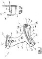
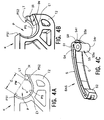
- FIG. 1 shows a known blade-type tensioner apparatus T' comprising a bracket K' typically defined from a metal stamping and a tensioner blade assembly BAS' operably secured to the bracket.
- the bracket K' is fixedly secured to an associated engine block EB as part of a chain drive system that is provided to phase or "time" the rotational position of one or more camshaft sprockets CMS with respect to the rotational position of the crankshaft sprocket CKS.
- One or more bolts or other fasteners BT' extend through mounting apertures KA' in a main wall MW' of the bracket K' and are threaded into the engine block EB or other associated support structure to fixedly secure the bracket K' in its operative position.
- a chain 15 such as a roller/bush chain or inverted tooth chain is engaged with the crankshaft sprocket CKS and the camshaft sprocket(s) CMS and phases/times the camshaft sprocket(s) to the crankshaft sprocket.
- the crankshaft sprocket CKS rotates in a direction DIR, and the chain 15 includes a taut strand portion 16 and a slack strand portion 17.
- the illustrated known tensioner T' comprises an optional first portion T1' that comprises a fixed guide flange XF' that projects transversely from the main wall MW' of the bracket K' and that is engaged with and supports a fixed chain guide FG' defined from a polymeric resinous material.
- the fixed chain guide FG' includes a guide face that slidably engages and supports/guides the taut strand 16 of the chain as shown in FIG. 1B .
- the tensioner T' further comprises a second portion T2' comprising the blade assembly BAS'.
- the bracket K' comprises a cold-headed steel or other pin N' that projects perpendicularly outward from the main wall MW' and that is welded or otherwise securely affixed to the main wall MW'.
- FIG. 1A is a section view taken at line 1A - 1A of FIG. 1 (of the bracket K' only without showing the blade assembly BAS') that shows the pivot pin N' secured to the main wall MW' of the bracket by a resistance weld or other weld NW'.
- the bracket K' further comprises a support flange TF' that projects outwardly from the main wall MW'.
- An end of the support flange TF' forms or defines a ramp R', and an outer wall OW' extends transversely from an outer end of the ramp R' and extends parallel to the main wall MW' such that a channel CH' ( FIG, 1A ) is defined between the main wall MW', the outer wall OW', and the ramp R'.
- a known tensioner blade assembly BAS' is operatively connected to the bracket K' and includes a polymeric or "plastic" shoe S' and a metal spring G' releasably connected to the shoe S'.
- a first or pivot end S1' of the blade assembly BAS' includes a boss or barrel S4' that includes pivot bore SB' that is slidably received onto the pivot pin N'.
- An opposite second or free end S2' of the blade assembly BAS' is located in the channel CH' and supported on the ramp R'.
- a retaining pin RP' shown in FIG. 1 is used for shipping and handling only to secure the free end S2' on the ramp R' and is removed for operation of the blade assembly BAS' as shown in FIGS. 1B and 1C .
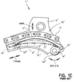
- the bracket K' maintains the blade assembly BAS' in its proper position with respect to the plane of the chain path while permitting sliding reciprocal translational motion of the second, free end S2' on the ramp R' as indicated by the arrow "TRANS” along with the related reciprocal angular or rotational movement of the blade assembly BAS' at the pivot end S1' as indicated by the arrow labeled "ROTATE" in response to changes in the tension and position of the slack strand 17 of the chain 15 and corresponding oscillatory movement of the slack strand 17 as indicated by the arrow "AMPL.”
- 1C is a partial view of the tensioner T' that shows this operative movement of the blade assembly BAS' using solid lines for a first (bowed) position of the blade assembly BAS' and phantom lines for a second (compressed) position of the blade assembly BAS'.
- the pivot pin N' can be replaced by a shoulder bolt or any other suitable fastener that extends through the shoe pivot bore SB' and through the bracket main wall MW' and that is threaded into the engine block EB or other associated support structure to allow rotation of the pivot end S1' of the shoe S' relative to the bracket K'.
- the tensioner T' comprises a pivot pin N' or a shoulder bolt
- the packaging environment is limited such that a stamped steel bracket with sufficient structural integrity cannot be packaged in the available space, or a stamped steel bracket K' is sometimes disfavored due to the required fixing/mounting point positions or for other packaging or design related reasons. As such, it has been deemed desirable to provide an alternative tensioner and tensioner bracket structure.
- a blade-type chain tensioner comprises a bracket including a main wall, a ramp projecting from the main wall, and a pivot pocket including an internal concave pivot surface.
- a tensioner blade assembly is operatively connected to the bracket.
- the tensioner blade assembly includes a polymeric shoe and a spring connected to the shoe.
- the shoe includes a free end supported on the ramp, a pivot end engaged with the pivot pocket, and a central body that extends between the free end and the pivot end.
- the pivot end of the shoe includes a pivot barrel including an external convex pivot surface.
- the pivot barrel is engaged with the pivot pocket and the external pivot surface of the pivot barrel is slidably abutted with the internal pivot surface of the pivot pocket such that the pivot barrel is reciprocally angularly movable in the pivot pocket.
- a blade-type chain tensioner includes a new bracket formed by injection molding a polymer or other polymeric or composite material such that the bracket includes a pocket pivot feature to permit relative rotation between the bracket and the pivot end of a tensioner blade assembly connected to the bracket.
- the pocket pivot feature includes a locking tab that captures the pivot end of the tensioner blade assembly to the bracket.
- Fiber glass filler or other filler material known in the art is normally added to the base polymer resin from which the bracket is defined (e.g., nylon or other resin) for improved strength of the bracket.
- the exemplary bracket provides advantages over known polymer brackets and over known brackets K' defined from steel stampings such as that described above in relation to FIGS. 1 - 1C .
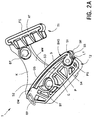
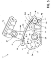
- FIG. 2A shows a front isometric view of an assembled tensioner T provided in accordance with the present development
- FIG. 2B provides a rear isometric view of the tensioner T
- FIG. 3 shows a front view of the tensioner T
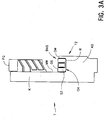
- FIG. 3A shows a side view of the tensioner T as taken according to the arrow 3A in FIG. 3
- FIGS. 2A shows a removable pin RP temporarily connected to the tensioner T for shipping and handling purposes. The removable pin RP is removed for operative use of the tensioner T.
- the tensioner T includes a bracket K defined from a nylon or other suitable polymeric or "plastic" material that typically includes glass fiber filler or other filler added thereto.
- the bracket K is a one-piece structure formed by injection molding or other like process.
- the bracket K includes a main wall MW.
- the tensioner T includes optional first portion or fixed guide portion T1 connected to a first end of the main wall MW, and a second portion or tensioner portion T2 connected to a second end of the main wall MW.
- the first portion T1 comprises a fixed guide flange XF that projects transversely from the main wall MW and that is engaged with and supports a fixed chain guide FG also defined from a polymeric resinous material.
- the fixed chain guide FG includes a guide face that slidably engages and supports the taut strand 16 of the chain 15 as described above in relation the known tensioner T' as shown in FIG. 1B .
- the second portion T2 of the tensioner T comprises a support flange or support ledge TF that projects outwardly from the main wall MW.
- an outer end of the support ledge TF forms or defines a ramp R
- an outer wall OW extends transversely from an outer end of the ramp R parallel to the main wall MW such that a channel CH is defined between the main wall MW, the outer wall OW, and the ramp R.
- the support ledge TF is provided by a surface of a support block KB portion of the bracket K that is connected to and extends or projects outwardly from the main wall MW.
- a tensioner blade assembly BAS provided in accordance with the present development is operatively connected to the bracket K as part of the second tensioner portion T2.
- the tensioner blade assembly BAS comprises a polymeric blade or "shoe” S and a metal spring G connected to the shoe S.
- the shoe S is a one-piece molded polymeric construction and the spring G is a one-piece spring steel part or similar leaf-spring structure.
- the shoe S includes a pivot end S1 and a free end S2 that define respective slots SL1,SL2 ( FIG. 5 ) for respectively receiving and retaining opposite ends of the spring G.
- the shoe S includes a central body S3 that extends along a chain travel axis between and interconnects the pivot and free ends S1,S2.
- An upper or outer surface OS of the central body S3 provides a chain contact surface for being slidably engaged by a chain being tensioned.
- the central body S3 includes a lower or inner surface located opposite the outer surface OS and that is contacted by an arched central portion of the spring G.
- the free end S2 of the shoe S is located in the channel CH and is supported on the ramp R (see also FIG. 3A ).
- the tensioner apparatus T is installed as part of an engine timing chain drive system in the same manner as described above for the known tensioner apparatus T' and as shown in FIG. 1B .
- One or more bolts BT are used to secure the bracket K to the associated engine block or other associated support structure of FIG. 1B such that a taut strand 16 of the chain 15 is guided by the fixed guide face FG and a slack strand 17 of the chain 15 is tensioned by the blade assembly BAS.
- the chain slack strand 17 sliding on the outer surface OS of the blade assembly BAS will cause the central body S3 of the shoe S to flatten and bow in an oscillatory manner such that the free end S2 of the shoe slides back-and-forth on the ramp R while the pivot end S1 of the shoe rotates or pivots with reciprocal angular movement in first and second angular directions relative to the bracket K.
- FIGS. 4A and 4B provide greatly enlarged partial views of the bracket K in the region of the pivot pocket P.
- the pivot pocket P comprises a concave pivot surface PS that includes or is defined by a cylindrical arc segment surface, i.e., a cylindrical surface that extends for less than 360 degrees about an arc center axis X.
- the pivot pocket P thus includes or defines an open mouth PM of width "d" defined between opposite first and second circumferential ends PS1,PS2 of the pivot surface PS at a point on the pivot surface PS where the width "d” is minimized, i.e., the width "d” is the minimum width open mouth defined between opposite circumferential ends PS1,PS2 of the pivot surface PS at the longest circumferential extent of the pivot surface.
- the pivot pocket P is defined in the support block KB, through or adjacent the support ledge TF at a location spaced from but aligned with the ramp R along the chain travel axis.
- the support block KB includes a recess KR to accommodate one of fastener bolts BT, and the recess KR intersects the support ledge TF and divides it into a first portion that comprises the ramp R and a second portion in which or adjacent to which the pivot pocket P is defined.
- the concave pivot surface PS is sometimes referred to herein as the internal pivot surface.
- the pivot end S1 of the shoe S correspondingly includes a pivot boss or pivot barrel S4 comprising a convex external cylindrical arc segment pivot surface S5, which comprises a cylindrical surface that extends circumferentially for less than 360 degrees.
- a primary region S5a of the external pivot surface S5 it extends substantially continuously from a front edge S4f to a rear edge S4r of the pivot barrel S4.
- the external pivot surface S5 is divided into front and rear sections S5f,S5r (see also FIG.
- an external strengthening rib SR that projects outwardly from the pivot barrel S4 in the region where the central portion S3 joins the pivot barrel S4, typically midway between the front and rear edges S4f,S4r of the pivot barrel.
- the front and rear sections S5f,S5r of the external pivot surface extend from the external strengthening rib to the front and rear edges, respectively.
- an outside diameter D is defined between any two diametrically opposed locations on said external pivot surface S5.
- the internal pivot surface PS of the pivot pocket P is conformed and dimensioned to correspond to the external pivot surface S5 of the pivot barrel S4, such that the outside diameter D defined by the pivot surface S5 fits closely into the pivot pocket P, with the external convex pivot surface S5 of the barrel S4 and the internal concave pivot surface PS of the pivot pocket P arranged coaxially about the pocket central axis X and slidably engaged or slidably abutted with each other.
- the pivot barrel S4 is able to rotate or pivot angularly in a reciprocal manner in first and second directions about the central axis X relative to the bracket K.
- the term “rotate” is not intended to mean 360 degrees of rotation. Instead, “rotation” is intended to mean angular movement along an arc segment, which will be less than 360 degrees.
- the pivot pocket P is defined such that the width "d" of the open mouth PM ( FIG. 4A ) is less than the pivot barrel outside diameter D, because the pivot surface PS extends for more than 180 degrees from its first end PS1 to its second end PS2 at its maximum circumferential length.
- the pivot barrel S4 is installed in the pivot pocket P by axial sliding movement of the pivot barrel S4 into the pivot pocket P along the pivot axis X.
- the pivot barrel S4 is interlocked to the bracket K and cannot move in any direction transverse to the pivot axis X, but the pivot barrel S4 can pivot relative to the bracket K in a reciprocal manner about the pivot axis X.
- an install notch IN ( FIG. 4B ) including an install ramp IR that provides clearance for the external rib SR of the shoe S when the pivot barrel S4 is moved axially along the pivot axis X into the pivot pocket P during its installation.
- the remaining portion of the second end PS2 of the pivot surface PS defines a locking tab LT that projects outwardly relative to the install ramp IR.
- the install ramp IR is sized such that upon axial insertion of the pivot barrel S4 into the pivot pocket P, the external rib SR will abut the locking tab LT when the pivot barrel S4 is fully axially installed into the pivot pocket P.
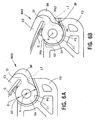
- FIGS. 5 and 6A show the tensioner blade assembly BAS oriented in an install position as required for axial insertion of the pivot barrel S4 into the pivot pocket P.
- the illustrated install position with the free end S2 of the shoe positioned spaced from the outer wall OW of the channel CH, is required in order for the free end S2 of the shoe S to move past or "clear" the outer channel wall OW when the pivot barrel S4 is axially inserted into the pivot pocket P.
- the external rib S5 is located parallel to and abutted with the "install" ramp IR such that the install ramp IR provides a reference location for the proper angular position of the tensioner blade assembly BAS for its installation.
- the pivot pocket P can optionally include a lead-in chamfer E1 adjacent its front edge to facilitate sliding insertion of the shoe pivot barrel S4.
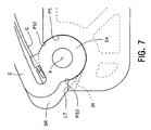
- FIGS. 6B and 7 show the tensioner blade assembly BAS installed in its operative position on the bracket K. It can be seen in FIG. 6B that when the tensioner blade assembly BAS is installed in its operative position, at least part of the external strengthening rib SR of the shoe S extends beyond the internal concave pivot surface PS of the pivot pocket P into the install notch IN and lies adjacent the locking tab LT. As such, the install notch IN provides clearance for the external strengthening rib SR.
Landscapes
- Engineering & Computer Science (AREA)
- General Engineering & Computer Science (AREA)
- Mechanical Engineering (AREA)
- Devices For Conveying Motion By Means Of Endless Flexible Members (AREA)
Applications Claiming Priority (2)
| Application Number | Priority Date | Filing Date | Title |
|---|---|---|---|
| US37830610P | 2010-08-30 | 2010-08-30 | |
| PCT/US2011/049520 WO2012030702A1 (en) | 2010-08-30 | 2011-08-29 | Blade tensioner and bracket for blade tensioner including pocket pivot feature |
Publications (2)
| Publication Number | Publication Date |
|---|---|
| EP2612054A1 EP2612054A1 (en) | 2013-07-10 |
| EP2612054B1 true EP2612054B1 (en) | 2016-04-20 |
Family
ID=44543894
Family Applications (1)
| Application Number | Title | Priority Date | Filing Date |
|---|---|---|---|
| EP11751779.7A Not-in-force EP2612054B1 (en) | 2010-08-30 | 2011-08-29 | Blade tensioner and bracket for blade tensioner including pocket pivot feature |
Country Status (5)
| Country | Link |
|---|---|
| US (1) | US8672785B2 (enExample) |
| EP (1) | EP2612054B1 (enExample) |
| JP (1) | JP5813115B2 (enExample) |
| CN (1) | CN103119330B (enExample) |
| WO (1) | WO2012030702A1 (enExample) |
Families Citing this family (14)
| Publication number | Priority date | Publication date | Assignee | Title |
|---|---|---|---|---|
| US9790817B2 (en) | 2012-10-22 | 2017-10-17 | Litens Automotive Partnership | Tensioner with increased damping |
| JP5997022B2 (ja) * | 2012-11-29 | 2016-09-21 | 株式会社椿本チエイン | チェーンガイド |
| JP5902873B2 (ja) * | 2012-12-09 | 2016-04-13 | クロイズ ギア アンド プロダクツ インコーポレイテッド | チェーンテンショナ |
| JP5848277B2 (ja) * | 2013-03-12 | 2016-01-27 | 株式会社椿本チエイン | チェーンガイド |
| JP5952225B2 (ja) * | 2013-06-26 | 2016-07-13 | 株式会社椿本チエイン | チェーンテンショナ |
| WO2015035508A1 (en) * | 2013-09-11 | 2015-03-19 | Litens Automotive Partnership | Tensioner with increased damping and arm on base cup configuration |
| WO2016144959A1 (en) * | 2015-03-09 | 2016-09-15 | Cloyes Gear And Products, Inc. | Chain tensioner plastic blade with improved structural rigidity at the spring-end reaction surfaces of the blade |
| DE102015011318A1 (de) * | 2015-08-28 | 2017-03-02 | Iwis Motorsysteme Gmbh & Co. Kg | Kettentrieb mit Kombinationsschiene |
| JP6408974B2 (ja) * | 2015-10-21 | 2018-10-17 | 株式会社椿本チエイン | チェーンガイド |
| US10487921B2 (en) * | 2016-12-21 | 2019-11-26 | Harley-Davidson Motor Company Group, LLC | Engine with inboard cam drive tensioner |
| JP6906840B2 (ja) * | 2017-04-07 | 2021-07-21 | 株式会社椿本チエイン | チェーンガイド機構 |
| JP7177343B2 (ja) * | 2018-10-16 | 2022-11-24 | 株式会社椿本チエイン | チェーンテンショナ |
| JP7525791B2 (ja) * | 2021-01-15 | 2024-07-31 | 株式会社椿本チエイン | チェーンガイド機構 |
| US11815180B2 (en) * | 2021-08-24 | 2023-11-14 | Schaeffler Technologies AG & Co. KG | Tensioner with stamped pivot pin |
Family Cites Families (17)
| Publication number | Priority date | Publication date | Assignee | Title |
|---|---|---|---|---|
| US3358522A (en) * | 1965-08-16 | 1967-12-19 | Morse Chain Co | Cam chain tensioner |
| US4155342A (en) * | 1977-11-02 | 1979-05-22 | Traweek Lowell E | Lasso gun |
| US5055088A (en) * | 1990-06-08 | 1991-10-08 | Borg-Warner Automotive, Inc. | Spring blade chain tensioner |
| US5425680A (en) | 1994-07-19 | 1995-06-20 | Cloyes Gear & Products, Inc. | Snap-fit chain tensioner apparatus and method |
| US5730674A (en) * | 1996-02-16 | 1998-03-24 | Ott; Vern D. | Primary drive chain tension adjuster |
| DE19717409A1 (de) | 1997-04-25 | 1998-10-29 | Schaeffler Waelzlager Ohg | Kettenspanner |
| JP2002536609A (ja) | 1999-02-10 | 2002-10-29 | クロイズ ギア アンド プロダクツ インコーポレイテッド | 限定された空間で使用するためのチェーンテンショナ装置 |
| JP2000230611A (ja) | 1999-02-15 | 2000-08-22 | Borg Warner Automotive Kk | ブレードテンショナ |
| US6238311B1 (en) * | 1999-10-27 | 2001-05-29 | Borgwarner Inc. | Blade tensioner with retaining pin and bracket |
| US6322469B1 (en) * | 2000-04-21 | 2001-11-27 | Borgwarner Inc. | Dual arm chain tensioner for contacting multiple chain strands |
| US6902505B2 (en) * | 2002-02-26 | 2005-06-07 | Borgwarner Morse Tec Japan K.K. | Blade-type tensioner |
| US7537533B2 (en) * | 2003-10-15 | 2009-05-26 | Borgwarner Inc. | Chain tensioning device linking two strands of a chain drive |
| US20060100048A1 (en) | 2004-11-08 | 2006-05-11 | Borgwarner Inc. | Tensioning device |
| US7641577B2 (en) * | 2005-06-28 | 2010-01-05 | Borgwarner Inc. | Mechanical chain tensioner with compliant blade spring |
| CN101415968B (zh) * | 2006-04-11 | 2013-12-18 | 博格华纳公司 | 串联弹簧叶片张紧器 |
| US7806034B1 (en) * | 2010-01-20 | 2010-10-05 | Lee Richard J | Safety prime feeding device |
| JP5813113B2 (ja) * | 2010-08-09 | 2015-11-17 | クロイズ ギア アンド プロダクツインコーポレイテッド | ばね保持機構を有するブレードテンショナ |
-
2011
- 2011-08-29 WO PCT/US2011/049520 patent/WO2012030702A1/en not_active Ceased
- 2011-08-29 JP JP2013527158A patent/JP5813115B2/ja not_active Expired - Fee Related
- 2011-08-29 CN CN201180041815.9A patent/CN103119330B/zh not_active Expired - Fee Related
- 2011-08-29 EP EP11751779.7A patent/EP2612054B1/en not_active Not-in-force
- 2011-08-29 US US13/220,021 patent/US8672785B2/en not_active Expired - Fee Related
Also Published As
| Publication number | Publication date |
|---|---|
| JP5813115B2 (ja) | 2015-11-17 |
| EP2612054A1 (en) | 2013-07-10 |
| US8672785B2 (en) | 2014-03-18 |
| WO2012030702A1 (en) | 2012-03-08 |
| JP2013538996A (ja) | 2013-10-17 |
| US20120052997A1 (en) | 2012-03-01 |
| CN103119330B (zh) | 2016-09-07 |
| CN103119330A (zh) | 2013-05-22 |
Similar Documents
| Publication | Publication Date | Title |
|---|---|---|
| EP2612054B1 (en) | Blade tensioner and bracket for blade tensioner including pocket pivot feature | |
| EP2603717B1 (en) | Blade tensioner with spring retaining features | |
| US7874950B2 (en) | Tensioner with reinstallation feature | |
| EP1157223B1 (en) | Chain tensioner device for use in a confined space | |
| US6623391B2 (en) | Blade-type mechanical chain tensioner with external strengthening rib | |
| US20100173738A1 (en) | Automatic Belt Tensioner | |
| US8465385B2 (en) | Chain guide mechanism | |
| CN1232530A (zh) | 汽车皮带张紧装置 | |
| MXPA04000457A (es) | Tensor de correa de transmision con pasador de instalacion. | |
| KR20160010499A (ko) | 댐핑이 개선된 텐셔너 | |
| JP4384663B2 (ja) | 調整可能なテンショナ | |
| JP2016520183A (ja) | 固定された支持体、プーリ、ベルト及びベルト・テンショナを含む組立体 | |
| JPH0712648U (ja) | オートテンショナ | |
| EP2929214B1 (en) | Chain tensioner | |
| WO2022182809A1 (en) | High-offset belt tensioner with counterbalance torsion spring force | |
| EP3987197B1 (en) | Tensioner | |
| US20130150192A1 (en) | Compliant guide device | |
| WO2001040682A1 (en) | Timing belt tensioner having a floating backstop | |
| JP5873381B2 (ja) | エンジンのチェーンガイド構造 | |
| JPH0687758U (ja) | オートテンショナ |
Legal Events
| Date | Code | Title | Description |
|---|---|---|---|
| PUAI | Public reference made under article 153(3) epc to a published international application that has entered the european phase |
Free format text: ORIGINAL CODE: 0009012 |
|
| 17P | Request for examination filed |
Effective date: 20130326 |
|
| AK | Designated contracting states |
Kind code of ref document: A1 Designated state(s): AL AT BE BG CH CY CZ DE DK EE ES FI FR GB GR HR HU IE IS IT LI LT LU LV MC MK MT NL NO PL PT RO RS SE SI SK SM TR |
|
| DAX | Request for extension of the european patent (deleted) | ||
| 17Q | First examination report despatched |
Effective date: 20141015 |
|
| GRAP | Despatch of communication of intention to grant a patent |
Free format text: ORIGINAL CODE: EPIDOSNIGR1 |
|
| INTG | Intention to grant announced |
Effective date: 20151112 |
|
| GRAS | Grant fee paid |
Free format text: ORIGINAL CODE: EPIDOSNIGR3 |
|
| GRAA | (expected) grant |
Free format text: ORIGINAL CODE: 0009210 |
|
| AK | Designated contracting states |
Kind code of ref document: B1 Designated state(s): AL AT BE BG CH CY CZ DE DK EE ES FI FR GB GR HR HU IE IS IT LI LT LU LV MC MK MT NL NO PL PT RO RS SE SI SK SM TR |
|
| REG | Reference to a national code |
Ref country code: GB Ref legal event code: FG4D |
|
| REG | Reference to a national code |
Ref country code: CH Ref legal event code: EP |
|
| REG | Reference to a national code |
Ref country code: AT Ref legal event code: REF Ref document number: 792810 Country of ref document: AT Kind code of ref document: T Effective date: 20160515 |
|
| REG | Reference to a national code |
Ref country code: IE Ref legal event code: FG4D |
|
| REG | Reference to a national code |
Ref country code: DE Ref legal event code: R096 Ref document number: 602011025638 Country of ref document: DE |
|
| REG | Reference to a national code |
Ref country code: LT Ref legal event code: MG4D |
|
| REG | Reference to a national code |
Ref country code: AT Ref legal event code: MK05 Ref document number: 792810 Country of ref document: AT Kind code of ref document: T Effective date: 20160420 |
|
| REG | Reference to a national code |
Ref country code: NL Ref legal event code: MP Effective date: 20160420 |
|
| PG25 | Lapsed in a contracting state [announced via postgrant information from national office to epo] |
Ref country code: NO Free format text: LAPSE BECAUSE OF FAILURE TO SUBMIT A TRANSLATION OF THE DESCRIPTION OR TO PAY THE FEE WITHIN THE PRESCRIBED TIME-LIMIT Effective date: 20160720 Ref country code: LT Free format text: LAPSE BECAUSE OF FAILURE TO SUBMIT A TRANSLATION OF THE DESCRIPTION OR TO PAY THE FEE WITHIN THE PRESCRIBED TIME-LIMIT Effective date: 20160420 Ref country code: PL Free format text: LAPSE BECAUSE OF FAILURE TO SUBMIT A TRANSLATION OF THE DESCRIPTION OR TO PAY THE FEE WITHIN THE PRESCRIBED TIME-LIMIT Effective date: 20160420 Ref country code: FI Free format text: LAPSE BECAUSE OF FAILURE TO SUBMIT A TRANSLATION OF THE DESCRIPTION OR TO PAY THE FEE WITHIN THE PRESCRIBED TIME-LIMIT Effective date: 20160420 Ref country code: NL Free format text: LAPSE BECAUSE OF FAILURE TO SUBMIT A TRANSLATION OF THE DESCRIPTION OR TO PAY THE FEE WITHIN THE PRESCRIBED TIME-LIMIT Effective date: 20160420 |
|
| PG25 | Lapsed in a contracting state [announced via postgrant information from national office to epo] |
Ref country code: LV Free format text: LAPSE BECAUSE OF FAILURE TO SUBMIT A TRANSLATION OF THE DESCRIPTION OR TO PAY THE FEE WITHIN THE PRESCRIBED TIME-LIMIT Effective date: 20160420 Ref country code: HR Free format text: LAPSE BECAUSE OF FAILURE TO SUBMIT A TRANSLATION OF THE DESCRIPTION OR TO PAY THE FEE WITHIN THE PRESCRIBED TIME-LIMIT Effective date: 20160420 Ref country code: RS Free format text: LAPSE BECAUSE OF FAILURE TO SUBMIT A TRANSLATION OF THE DESCRIPTION OR TO PAY THE FEE WITHIN THE PRESCRIBED TIME-LIMIT Effective date: 20160420 Ref country code: SE Free format text: LAPSE BECAUSE OF FAILURE TO SUBMIT A TRANSLATION OF THE DESCRIPTION OR TO PAY THE FEE WITHIN THE PRESCRIBED TIME-LIMIT Effective date: 20160420 Ref country code: GR Free format text: LAPSE BECAUSE OF FAILURE TO SUBMIT A TRANSLATION OF THE DESCRIPTION OR TO PAY THE FEE WITHIN THE PRESCRIBED TIME-LIMIT Effective date: 20160721 Ref country code: AT Free format text: LAPSE BECAUSE OF FAILURE TO SUBMIT A TRANSLATION OF THE DESCRIPTION OR TO PAY THE FEE WITHIN THE PRESCRIBED TIME-LIMIT Effective date: 20160420 Ref country code: ES Free format text: LAPSE BECAUSE OF FAILURE TO SUBMIT A TRANSLATION OF THE DESCRIPTION OR TO PAY THE FEE WITHIN THE PRESCRIBED TIME-LIMIT Effective date: 20160420 Ref country code: PT Free format text: LAPSE BECAUSE OF FAILURE TO SUBMIT A TRANSLATION OF THE DESCRIPTION OR TO PAY THE FEE WITHIN THE PRESCRIBED TIME-LIMIT Effective date: 20160822 |
|
| PG25 | Lapsed in a contracting state [announced via postgrant information from national office to epo] |
Ref country code: BE Free format text: LAPSE BECAUSE OF FAILURE TO SUBMIT A TRANSLATION OF THE DESCRIPTION OR TO PAY THE FEE WITHIN THE PRESCRIBED TIME-LIMIT Effective date: 20160420 Ref country code: IT Free format text: LAPSE BECAUSE OF FAILURE TO SUBMIT A TRANSLATION OF THE DESCRIPTION OR TO PAY THE FEE WITHIN THE PRESCRIBED TIME-LIMIT Effective date: 20160420 |
|
| REG | Reference to a national code |
Ref country code: DE Ref legal event code: R097 Ref document number: 602011025638 Country of ref document: DE |
|
| PG25 | Lapsed in a contracting state [announced via postgrant information from national office to epo] |
Ref country code: CZ Free format text: LAPSE BECAUSE OF FAILURE TO SUBMIT A TRANSLATION OF THE DESCRIPTION OR TO PAY THE FEE WITHIN THE PRESCRIBED TIME-LIMIT Effective date: 20160420 Ref country code: SK Free format text: LAPSE BECAUSE OF FAILURE TO SUBMIT A TRANSLATION OF THE DESCRIPTION OR TO PAY THE FEE WITHIN THE PRESCRIBED TIME-LIMIT Effective date: 20160420 Ref country code: EE Free format text: LAPSE BECAUSE OF FAILURE TO SUBMIT A TRANSLATION OF THE DESCRIPTION OR TO PAY THE FEE WITHIN THE PRESCRIBED TIME-LIMIT Effective date: 20160420 Ref country code: RO Free format text: LAPSE BECAUSE OF FAILURE TO SUBMIT A TRANSLATION OF THE DESCRIPTION OR TO PAY THE FEE WITHIN THE PRESCRIBED TIME-LIMIT Effective date: 20160420 Ref country code: DK Free format text: LAPSE BECAUSE OF FAILURE TO SUBMIT A TRANSLATION OF THE DESCRIPTION OR TO PAY THE FEE WITHIN THE PRESCRIBED TIME-LIMIT Effective date: 20160420 |
|
| PLBE | No opposition filed within time limit |
Free format text: ORIGINAL CODE: 0009261 |
|
| STAA | Information on the status of an ep patent application or granted ep patent |
Free format text: STATUS: NO OPPOSITION FILED WITHIN TIME LIMIT |
|
| PG25 | Lapsed in a contracting state [announced via postgrant information from national office to epo] |
Ref country code: SM Free format text: LAPSE BECAUSE OF FAILURE TO SUBMIT A TRANSLATION OF THE DESCRIPTION OR TO PAY THE FEE WITHIN THE PRESCRIBED TIME-LIMIT Effective date: 20160420 |
|
| 26N | No opposition filed |
Effective date: 20170123 |
|
| PG25 | Lapsed in a contracting state [announced via postgrant information from national office to epo] |
Ref country code: MC Free format text: LAPSE BECAUSE OF FAILURE TO SUBMIT A TRANSLATION OF THE DESCRIPTION OR TO PAY THE FEE WITHIN THE PRESCRIBED TIME-LIMIT Effective date: 20160420 |
|
| REG | Reference to a national code |
Ref country code: CH Ref legal event code: PL |
|
| PG25 | Lapsed in a contracting state [announced via postgrant information from national office to epo] |
Ref country code: CH Free format text: LAPSE BECAUSE OF NON-PAYMENT OF DUE FEES Effective date: 20160831 Ref country code: LI Free format text: LAPSE BECAUSE OF NON-PAYMENT OF DUE FEES Effective date: 20160831 |
|
| REG | Reference to a national code |
Ref country code: FR Ref legal event code: ST Effective date: 20170428 |
|
| PG25 | Lapsed in a contracting state [announced via postgrant information from national office to epo] |
Ref country code: SI Free format text: LAPSE BECAUSE OF FAILURE TO SUBMIT A TRANSLATION OF THE DESCRIPTION OR TO PAY THE FEE WITHIN THE PRESCRIBED TIME-LIMIT Effective date: 20160420 |
|
| REG | Reference to a national code |
Ref country code: IE Ref legal event code: MM4A |
|
| PG25 | Lapsed in a contracting state [announced via postgrant information from national office to epo] |
Ref country code: IE Free format text: LAPSE BECAUSE OF NON-PAYMENT OF DUE FEES Effective date: 20160829 Ref country code: FR Free format text: LAPSE BECAUSE OF NON-PAYMENT OF DUE FEES Effective date: 20160831 |
|
| PG25 | Lapsed in a contracting state [announced via postgrant information from national office to epo] |
Ref country code: LU Free format text: LAPSE BECAUSE OF NON-PAYMENT OF DUE FEES Effective date: 20160829 |
|
| PGFP | Annual fee paid to national office [announced via postgrant information from national office to epo] |
Ref country code: GB Payment date: 20170725 Year of fee payment: 7 Ref country code: DE Payment date: 20170825 Year of fee payment: 7 |
|
| PG25 | Lapsed in a contracting state [announced via postgrant information from national office to epo] |
Ref country code: CY Free format text: LAPSE BECAUSE OF FAILURE TO SUBMIT A TRANSLATION OF THE DESCRIPTION OR TO PAY THE FEE WITHIN THE PRESCRIBED TIME-LIMIT Effective date: 20160420 Ref country code: HU Free format text: LAPSE BECAUSE OF FAILURE TO SUBMIT A TRANSLATION OF THE DESCRIPTION OR TO PAY THE FEE WITHIN THE PRESCRIBED TIME-LIMIT; INVALID AB INITIO Effective date: 20110829 |
|
| PG25 | Lapsed in a contracting state [announced via postgrant information from national office to epo] |
Ref country code: MT Free format text: LAPSE BECAUSE OF NON-PAYMENT OF DUE FEES Effective date: 20160831 Ref country code: TR Free format text: LAPSE BECAUSE OF FAILURE TO SUBMIT A TRANSLATION OF THE DESCRIPTION OR TO PAY THE FEE WITHIN THE PRESCRIBED TIME-LIMIT Effective date: 20160420 Ref country code: IS Free format text: LAPSE BECAUSE OF FAILURE TO SUBMIT A TRANSLATION OF THE DESCRIPTION OR TO PAY THE FEE WITHIN THE PRESCRIBED TIME-LIMIT Effective date: 20160420 Ref country code: MK Free format text: LAPSE BECAUSE OF FAILURE TO SUBMIT A TRANSLATION OF THE DESCRIPTION OR TO PAY THE FEE WITHIN THE PRESCRIBED TIME-LIMIT Effective date: 20160420 |
|
| PG25 | Lapsed in a contracting state [announced via postgrant information from national office to epo] |
Ref country code: BG Free format text: LAPSE BECAUSE OF FAILURE TO SUBMIT A TRANSLATION OF THE DESCRIPTION OR TO PAY THE FEE WITHIN THE PRESCRIBED TIME-LIMIT Effective date: 20160420 |
|
| PG25 | Lapsed in a contracting state [announced via postgrant information from national office to epo] |
Ref country code: AL Free format text: LAPSE BECAUSE OF FAILURE TO SUBMIT A TRANSLATION OF THE DESCRIPTION OR TO PAY THE FEE WITHIN THE PRESCRIBED TIME-LIMIT Effective date: 20160420 |
|
| REG | Reference to a national code |
Ref country code: DE Ref legal event code: R119 Ref document number: 602011025638 Country of ref document: DE |
|
| GBPC | Gb: european patent ceased through non-payment of renewal fee |
Effective date: 20180829 |
|
| PG25 | Lapsed in a contracting state [announced via postgrant information from national office to epo] |
Ref country code: DE Free format text: LAPSE BECAUSE OF NON-PAYMENT OF DUE FEES Effective date: 20190301 |
|
| PG25 | Lapsed in a contracting state [announced via postgrant information from national office to epo] |
Ref country code: GB Free format text: LAPSE BECAUSE OF NON-PAYMENT OF DUE FEES Effective date: 20180829 |