EP2610443A1 - Actuating Device for the Rotation of a Turbine Shaft Train - Google Patents
Actuating Device for the Rotation of a Turbine Shaft Train Download PDFInfo
- Publication number
- EP2610443A1 EP2610443A1 EP12197678.1A EP12197678A EP2610443A1 EP 2610443 A1 EP2610443 A1 EP 2610443A1 EP 12197678 A EP12197678 A EP 12197678A EP 2610443 A1 EP2610443 A1 EP 2610443A1
- Authority
- EP
- European Patent Office
- Prior art keywords
- cylinder
- actuating device
- rod
- actuator
- wheel
- Prior art date
- Legal status (The legal status is an assumption and is not a legal conclusion. Google has not performed a legal analysis and makes no representation as to the accuracy of the status listed.)
- Granted
Links
Images



Classifications
-
- F—MECHANICAL ENGINEERING; LIGHTING; HEATING; WEAPONS; BLASTING
- F16—ENGINEERING ELEMENTS AND UNITS; GENERAL MEASURES FOR PRODUCING AND MAINTAINING EFFECTIVE FUNCTIONING OF MACHINES OR INSTALLATIONS; THERMAL INSULATION IN GENERAL
- F16H—GEARING
- F16H35/00—Gearings or mechanisms with other special functional features
-
- F—MECHANICAL ENGINEERING; LIGHTING; HEATING; WEAPONS; BLASTING
- F01—MACHINES OR ENGINES IN GENERAL; ENGINE PLANTS IN GENERAL; STEAM ENGINES
- F01D—NON-POSITIVE DISPLACEMENT MACHINES OR ENGINES, e.g. STEAM TURBINES
- F01D25/00—Component parts, details, or accessories, not provided for in, or of interest apart from, other groups
- F01D25/34—Turning or inching gear
-
- F—MECHANICAL ENGINEERING; LIGHTING; HEATING; WEAPONS; BLASTING
- F01—MACHINES OR ENGINES IN GENERAL; ENGINE PLANTS IN GENERAL; STEAM ENGINES
- F01D—NON-POSITIVE DISPLACEMENT MACHINES OR ENGINES, e.g. STEAM TURBINES
- F01D25/00—Component parts, details, or accessories, not provided for in, or of interest apart from, other groups
- F01D25/34—Turning or inching gear
- F01D25/36—Turning or inching gear using electric motors
-
- F—MECHANICAL ENGINEERING; LIGHTING; HEATING; WEAPONS; BLASTING
- F16—ENGINEERING ELEMENTS AND UNITS; GENERAL MEASURES FOR PRODUCING AND MAINTAINING EFFECTIVE FUNCTIONING OF MACHINES OR INSTALLATIONS; THERMAL INSULATION IN GENERAL
- F16H—GEARING
- F16H1/00—Toothed gearings for conveying rotary motion
- F16H1/02—Toothed gearings for conveying rotary motion without gears having orbital motion
- F16H1/04—Toothed gearings for conveying rotary motion without gears having orbital motion involving only two intermeshing members
- F16H1/06—Toothed gearings for conveying rotary motion without gears having orbital motion involving only two intermeshing members with parallel axes
-
- F—MECHANICAL ENGINEERING; LIGHTING; HEATING; WEAPONS; BLASTING
- F16—ENGINEERING ELEMENTS AND UNITS; GENERAL MEASURES FOR PRODUCING AND MAINTAINING EFFECTIVE FUNCTIONING OF MACHINES OR INSTALLATIONS; THERMAL INSULATION IN GENERAL
- F16H—GEARING
- F16H31/00—Other gearings with freewheeling members or other intermittently driving members
- F16H31/003—Step-by-step mechanisms for rotary motion
- F16H31/005—Step-by-step mechanisms for rotary motion with pawls driven by a reciprocating or oscillating transmission member
-
- F—MECHANICAL ENGINEERING; LIGHTING; HEATING; WEAPONS; BLASTING
- F05—INDEXING SCHEMES RELATING TO ENGINES OR PUMPS IN VARIOUS SUBCLASSES OF CLASSES F01-F04
- F05B—INDEXING SCHEME RELATING TO WIND, SPRING, WEIGHT, INERTIA OR LIKE MOTORS, TO MACHINES OR ENGINES FOR LIQUIDS COVERED BY SUBCLASSES F03B, F03D AND F03G
- F05B2220/00—Application
- F05B2220/30—Application in turbines
- F05B2220/301—Application in turbines in steam turbines
-
- F—MECHANICAL ENGINEERING; LIGHTING; HEATING; WEAPONS; BLASTING
- F05—INDEXING SCHEMES RELATING TO ENGINES OR PUMPS IN VARIOUS SUBCLASSES OF CLASSES F01-F04
- F05B—INDEXING SCHEME RELATING TO WIND, SPRING, WEIGHT, INERTIA OR LIKE MOTORS, TO MACHINES OR ENGINES FOR LIQUIDS COVERED BY SUBCLASSES F03B, F03D AND F03G
- F05B2260/00—Function
- F05B2260/85—Starting
-
- F—MECHANICAL ENGINEERING; LIGHTING; HEATING; WEAPONS; BLASTING
- F05—INDEXING SCHEMES RELATING TO ENGINES OR PUMPS IN VARIOUS SUBCLASSES OF CLASSES F01-F04
- F05D—INDEXING SCHEME FOR ASPECTS RELATING TO NON-POSITIVE-DISPLACEMENT MACHINES OR ENGINES, GAS-TURBINES OR JET-PROPULSION PLANTS
- F05D2220/00—Application
- F05D2220/30—Application in turbines
- F05D2220/31—Application in turbines in steam turbines
-
- F—MECHANICAL ENGINEERING; LIGHTING; HEATING; WEAPONS; BLASTING
- F05—INDEXING SCHEMES RELATING TO ENGINES OR PUMPS IN VARIOUS SUBCLASSES OF CLASSES F01-F04
- F05D—INDEXING SCHEME FOR ASPECTS RELATING TO NON-POSITIVE-DISPLACEMENT MACHINES OR ENGINES, GAS-TURBINES OR JET-PROPULSION PLANTS
- F05D2260/00—Function
- F05D2260/85—Starting
-
- F—MECHANICAL ENGINEERING; LIGHTING; HEATING; WEAPONS; BLASTING
- F15—FLUID-PRESSURE ACTUATORS; HYDRAULICS OR PNEUMATICS IN GENERAL
- F15B—SYSTEMS ACTING BY MEANS OF FLUIDS IN GENERAL; FLUID-PRESSURE ACTUATORS, e.g. SERVOMOTORS; DETAILS OF FLUID-PRESSURE SYSTEMS, NOT OTHERWISE PROVIDED FOR
- F15B15/00—Fluid-actuated devices for displacing a member from one position to another; Gearing associated therewith
- F15B15/02—Mechanical layout characterised by the means for converting the movement of the fluid-actuated element into movement of the finally-operated member
- F15B15/06—Mechanical layout characterised by the means for converting the movement of the fluid-actuated element into movement of the finally-operated member for mechanically converting rectilinear movement into non- rectilinear movement
- F15B15/061—Mechanical layout characterised by the means for converting the movement of the fluid-actuated element into movement of the finally-operated member for mechanically converting rectilinear movement into non- rectilinear movement by unidirectional means
-
- Y—GENERAL TAGGING OF NEW TECHNOLOGICAL DEVELOPMENTS; GENERAL TAGGING OF CROSS-SECTIONAL TECHNOLOGIES SPANNING OVER SEVERAL SECTIONS OF THE IPC; TECHNICAL SUBJECTS COVERED BY FORMER USPC CROSS-REFERENCE ART COLLECTIONS [XRACs] AND DIGESTS
- Y10—TECHNICAL SUBJECTS COVERED BY FORMER USPC
- Y10T—TECHNICAL SUBJECTS COVERED BY FORMER US CLASSIFICATION
- Y10T74/00—Machine element or mechanism
- Y10T74/19—Gearing
- Y10T74/19637—Gearing with brake means for gearing
-
- Y—GENERAL TAGGING OF NEW TECHNOLOGICAL DEVELOPMENTS; GENERAL TAGGING OF CROSS-SECTIONAL TECHNOLOGIES SPANNING OVER SEVERAL SECTIONS OF THE IPC; TECHNICAL SUBJECTS COVERED BY FORMER USPC CROSS-REFERENCE ART COLLECTIONS [XRACs] AND DIGESTS
- Y10—TECHNICAL SUBJECTS COVERED BY FORMER USPC
- Y10T—TECHNICAL SUBJECTS COVERED BY FORMER US CLASSIFICATION
- Y10T74/00—Machine element or mechanism
- Y10T74/19—Gearing
- Y10T74/19642—Directly cooperating gears
Definitions
- the present invention relates to the field of turbine-generator sets. It concerns steam turbines in particular, although it could also be applied to gas turbines. Turbines of this kind are utilized in electricity generation plants, each turbine driving an alternator for generating electricity. This may be a plant operating on the basis of energy of fossil or nuclear origin.
- the invention relates to an actuating device for causing a turbine shaft train to rotate.
- the shaft train comprises the rotors of each turbine module, as well as that of the alternator.
- the rotation of the shaft train also referred to as turning, is generally achieved with the help of an electric motor capable of overcoming the resistive torque of the shaft train.
- the electric motor drives a reduction gear which actuates the shaft train. It is necessary to maintain the rotation of the shaft train during periods of starting and stopping the turbine-generator set in order to equalize the temperatures of the rotor and thereby to avoid all bending of the shaft train under the effect of thermal dissymmetry.
- the electric motor also allows the rotation of the shaft train to be initiated during a starting phase ahead of the injection of steam into the turbine.
- the speed of rotation of the shaft train is low and constant during these phases. It varies from a few revolutions per minute to a few tens of revolutions per minute depending on the turbine-generator sets concerned.
- a turning gear controlled by an electric motor does not allow a very low speed of rotation to be achieved, or the low-amplitude angular displacements of the shaft train that are necessary during maintenance operations.
- the object of the present invention is thus to overcome these disadvantages by proposing an actuating device for a turbine shaft train as well as a turbine-generator set.
- the actuating device for causing the turbine shaft train to rotate comprises an electrically operated principal turning gear and a hydraulically operated auxiliary turning gear.
- the auxiliary turning gear permits the achievement of angular displacements of the shaft train that are controlled and of low amplitude.
- the auxiliary turning gear exhibits the advantage that it is possible in this way to have an emergency turning gear at one's disposal in the event of failure of the principal turning gear. It also permits the inertia of the shaft train to be overcome and the latter to be released from the bearings. In addition, it is possible to position the auxiliary turning gear at any point on the shaft train, which allows considerable flexibility in the layout of the plant.
- the auxiliary turning gear is controlled by the rod of a double-acting hydraulic cylinder. This characteristic permits the rotation of the shaft train to be controlled precisely.
- the auxiliary turning gear comprises a wheel that is integral with the shaft train and an actuator connected to the rod of the cylinder, the actuator being capable of engaging driving means arranged on the periphery of the wheel and being capable of displacement between a retracted position disengaged from the wheel and a position of engagement with one of the driving means, in which an extension movement of the rod of the cylinder controls the rotation of the wheel.
- the invention also relates to a turbine-generator set for the generation of electricity comprising an actuating device having all or some of the aforementioned characteristics.
- Figure 1 depicts a turbine-generator set for the generation of electricity comprising a group of steam turbine modules, in this case being three turbine modules T1,T2,T3, driving an alternator 3.
- This turbine-generator set rests on a rigid supporting structure 4, generally made of concrete.
- the rotors of the turbine modules drive the alternator 3 causing it to rotate about the shaft A, the alternator being situated behind the turbine-generator set.
- the shaft train 1 extends forwards, at its opposite extremity to the alternator 3, as far as a housing comprising an actuating device consisting on the one hand of a principal turning gear and on the other hand of an auxiliary turning gear.
- the principal electrically operated turning gear is actuated by an electric motor permitting the shaft train 1 to be driven via a clutch system.
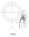
- the auxiliary turning gear 5 illustrated in figure 2 has hydraulic control by means of a cylinder 6.
- the auxiliary turning gear permits the shaft train to be caused to rotate through small portions of an angle and the shaft train to be positioned accurately during maintenance operations. It also permits the shaft train to be caused to rotate at a constant speed of a few revolutions per hour.
- the auxiliary turning gear can serve as an emergency turning gear in the event of failure of the principal turning gear, and particularly in the case of its turning for the stopping phase.
- the auxiliary turning gear will preferably perform a discontinuous rotation.
- a step-by-step rotation is preferable in this case. Its angle will be in the order of 5 to 10 degrees. Its speed of rotation will favorably lie in the range between 1 and 10 revolutions/hour.
- the speed of rotation of the principal turning gear will favorably be higher than that of the auxiliary turning gear.
- the speed of the auxiliary turning gear will thus permit the maintenance operations and will, in particular, make it possible to cause the rotor to rotate at a desired angle.
- Both the principal turning gear and the auxiliary turning gear may be positioned between two turbine modules (T1,T2,T3) or between the final turbine module (T3) and the alternator 3.
- the auxiliary turning gear 5 ( figure 2 ) is controlled by the rod 61 of the hydraulic cylinder 6, which is a double-acting cylinder.
- the auxiliary turning gear comprises a wheel 10 that is integral with the shaft train 1 and an actuator 8 connected to the rod 61 of the cylinder 6.
- the actuator 8 is capable of engaging driving means 11 arranged on the periphery of the wheel.
- Each driving means 11 exhibits a hollow part 110 adapted to receive a complementary form 19 of the actuator 8.
- the hollow part 110 and the form 19 have complementary cylindrical forms in order to ensure satisfactory engagement.
- the actuator 8 is connected via an articulation 9 to the rod 61 of the cylinder 6.
- the actuator 8 is capable of displacement between a retracted position disengaged from the wheel 10 ( figures 2 and 5a ) and an engagement position with the driving means 11 ( figure 5b ).
- the engagement position the extension movement of the rod 61 from the cylinder 6 controls the rotation of the wheel 10 and consequently that of the shaft train 1.
- the amplitude of the rotation is controlled with precision by the displacement of the cylinder rod 61.
- the body of the cylinder 62 is fixed to a carrier plate 12, which is itself fixed to a component 14.
- the whole assembly is fixed to the component 13 that is connected rigidly to the supporting structure 4, advantageously at the level of a housing.
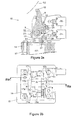
- the carrier plate 12 supports the actuating mechanism 15 for the auxiliary turning gear 5, which is illustrated in detail in figures 3a, 3b and 4 .
- the actuating mechanism 15 is supported by a plate 14 fixed by means of screws to the carrier plate 12.
- the plate 14 exhibits two columns 16a,16b provided with guiding means 161A, 161b for a slide 17 that is integral with the rod 61 of the cylinder 6.
- the actuator 8 is connected to the rod of the cylinder by means of an articulation comprising a shaft 9 supported by the slide 17 in such a way as to be capable of pivoting between the retracted position and the engagement position.
- the slide 17 is guided in translational movement by the guiding means 161a, 161b supported by the plate 14 that is integral with the body of the cylinder via the carrier plate 12.
- the guiding means 161a, 161b are constituted by plates applied to the columns 16a, 16b.
- the slide 17 has a U-shaped form ( figure 4 ), of which the bottom part is fixed to the rod 61 of the cylinder 6.
- the lateral uprights 17a,17b of the U support the pivot shaft 9 for the articulation.
- These lateral uprights exhibit a complementary part 171a,171b bearing against the guiding means 161a,161b.
- the actuator 8 exhibits the form of a slightly bent connecting rod, of which the lower part is pivotally mounted on the shaft 9. Its upper part exhibits a cylindrical form 19 which will lodge in one of the hollow parts 110 arranged on the periphery of the wheel 10.
- the bottom part of the actuator 8 exhibits in the vicinity of the shaft 9 a surface 20 which will bear against a first fixed stop 21 that is integral with the plate 14 during a retraction movement of the rod 61 of the cylinder 6.
- the first stop 21 is situated on the side of the wheel 10.
- a spring 22 is arranged between the actuator 8 and the plate 14. It is positioned in the interior of a housing 23 provided in the actuator 8 on the side opposite the stop 21 in relation to the shaft 9. The spring pushes against a finger 24 that is slidably mounted in the housing 23.
- the finger 24 exhibits a bottom part 25 which projects towards the bottom out of the housing 23.
- the bottom part 25 normally rests on a supporting member 26 that is integral with the slide 17.
- the spring 22 causes the actuator 8 to tilt towards the position of engagement with one of the driving means 11 in a hollow part 110 of the wheel 10 as illustrated in figure 5b .
- the surface 20 comes into contact with the first stop 21 ( figure 5a ), the effect of which is to displace the actuator 8 towards the retracted position disengaged from the wheel 10.
- Figure 5c illustrates the case in which, the rod of the cylinder 61 being in an extended position, the speed V of rotation of the shaft train 1 begins to increase, as is the case, for example, when the turbines are being driven by steam.
- an inclined part 111 of a driving means 11 will eject (arrow E) the cylindrical form 19 towards the exterior of the wheel 10.
- the actuator 8 then tilts towards the ejection position represented in figure 5c , in which the part 25 of the finger 24 pushed back by the spring 22 will lodge in a cavity 27 in the slide 17. Once it has lodged in this cavity 27, the finger 24 immobilizes the actuator 8 in the ejection position.
- the part 25 of the finger 24 enters into contact ( figure 5a ) with a second fixed stop 28 that is integral with the plate 14.
- the effect of the contact with this second stop 28 is to place the part 25 of the finger 24 in contact on the supporting member 26 ( figures 5a and 3 ).
- the actuating mechanism 15 is then ready to function normally as described in relation to figures 5a and 5b .
- the second fixed stop 28 is arranged on the side opposite the first fixed stop 21 in relation to the rod 61.
- the actuating mechanism is provided with two end of travel detecting devices 31,32.
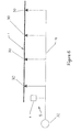
- Illustrated schematically in figure 6 is an oil circuit under high pressure which supplies bearings 30 of the shaft train 1.
- auxiliary turning gear 5, in particular its hydraulic cylinder 6, is supplied with oil under high pressure by this circuit 70 for supplying oil to the bearings.
- the rotor must be subjected to lifting during any turning phase. This lifting is achieved by the injection of oil under high pressure at the site of the bearings 30.
- the operation of the hydraulic cylinder 6 also requires an oil under high pressure.
- the high-pressure oil utilized by the cylinder 6 will arrive by preference from a pump 32 on the circuit 70 which permits the lifting of the shaft train, and all the more so given that this circuit is active when the cylinder is in operation, since it supplies oil to the bearings.
Landscapes
- Engineering & Computer Science (AREA)
- General Engineering & Computer Science (AREA)
- Mechanical Engineering (AREA)
- Connection Of Motors, Electrical Generators, Mechanical Devices, And The Like (AREA)
- Transmission Devices (AREA)
- Mechanical Operated Clutches (AREA)
Abstract
Description
- The present invention relates to the field of turbine-generator sets. It concerns steam turbines in particular, although it could also be applied to gas turbines. Turbines of this kind are utilized in electricity generation plants, each turbine driving an alternator for generating electricity. This may be a plant operating on the basis of energy of fossil or nuclear origin.
- More particularly, the invention relates to an actuating device for causing a turbine shaft train to rotate. The shaft train comprises the rotors of each turbine module, as well as that of the alternator. The rotation of the shaft train, also referred to as turning, is generally achieved with the help of an electric motor capable of overcoming the resistive torque of the shaft train. The electric motor drives a reduction gear which actuates the shaft train. It is necessary to maintain the rotation of the shaft train during periods of starting and stopping the turbine-generator set in order to equalize the temperatures of the rotor and thereby to avoid all bending of the shaft train under the effect of thermal dissymmetry. The electric motor also allows the rotation of the shaft train to be initiated during a starting phase ahead of the injection of steam into the turbine. The speed of rotation of the shaft train is low and constant during these phases. It varies from a few revolutions per minute to a few tens of revolutions per minute depending on the turbine-generator sets concerned.
- However, a turning gear controlled by an electric motor does not allow a very low speed of rotation to be achieved, or the low-amplitude angular displacements of the shaft train that are necessary during maintenance operations.
- The object of the present invention is thus to overcome these disadvantages by proposing an actuating device for a turbine shaft train as well as a turbine-generator set.
- According to a first characteristic, the actuating device for causing the turbine shaft train to rotate comprises an electrically operated principal turning gear and a hydraulically operated auxiliary turning gear. The auxiliary turning gear permits the achievement of angular displacements of the shaft train that are controlled and of low amplitude. The auxiliary turning gear exhibits the advantage that it is possible in this way to have an emergency turning gear at one's disposal in the event of failure of the principal turning gear. It also permits the inertia of the shaft train to be overcome and the latter to be released from the bearings. In addition, it is possible to position the auxiliary turning gear at any point on the shaft train, which allows considerable flexibility in the layout of the plant.
- According to one particular characteristic, the auxiliary turning gear is controlled by the rod of a double-acting hydraulic cylinder. This characteristic permits the rotation of the shaft train to be controlled precisely.
- According to another characteristic, the auxiliary turning gear comprises a wheel that is integral with the shaft train and an actuator connected to the rod of the cylinder, the actuator being capable of engaging driving means arranged on the periphery of the wheel and being capable of displacement between a retracted position disengaged from the wheel and a position of engagement with one of the driving means, in which an extension movement of the rod of the cylinder controls the rotation of the wheel.
- The invention also relates to a turbine-generator set for the generation of electricity comprising an actuating device having all or some of the aforementioned characteristics.
- Other characteristics and advantages of the invention will become apparent from reading the following description with reference to the figures attached hereto, which illustrate the following by way of example:
-
figure 1 is a perspective view of a turbine-generator set for the generation of electricity according to the invention, -
figure 2 depicts the auxiliary turning gear according to the invention, -
figure 3a depicts the actuator for the auxiliary turning gear according to section IIIa infigure 3b , -
figure 3b depicts the actuator of the auxiliary turning gear in plan view, -
figure 4 depicts the actuator in perspective and as an exploded view, -
figures 5a,5b,5c depict the actuator in different positions, - and
figure 6 shows an oil circuit under high pressure supplying the bearings of a shaft train. -
Figure 1 depicts a turbine-generator set for the generation of electricity comprising a group of steam turbine modules, in this case being three turbine modules T1,T2,T3, driving analternator 3. This turbine-generator set rests on a rigid supportingstructure 4, generally made of concrete. The rotors of the turbine modules drive thealternator 3 causing it to rotate about the shaft A, the alternator being situated behind the turbine-generator set. Theshaft train 1 extends forwards, at its opposite extremity to thealternator 3, as far as a housing comprising an actuating device consisting on the one hand of a principal turning gear and on the other hand of an auxiliary turning gear. The principal electrically operated turning gear is actuated by an electric motor permitting theshaft train 1 to be driven via a clutch system. Theauxiliary turning gear 5 illustrated infigure 2 has hydraulic control by means of acylinder 6. The auxiliary turning gear permits the shaft train to be caused to rotate through small portions of an angle and the shaft train to be positioned accurately during maintenance operations. It also permits the shaft train to be caused to rotate at a constant speed of a few revolutions per hour. The auxiliary turning gear can serve as an emergency turning gear in the event of failure of the principal turning gear, and particularly in the case of its turning for the stopping phase. The auxiliary turning gear will preferably perform a discontinuous rotation. A step-by-step rotation is preferable in this case. Its angle will be in the order of 5 to 10 degrees. Its speed of rotation will favorably lie in the range between 1 and 10 revolutions/hour. - As far as the principal turning gear is concerned, its rotation will preferably be continuous. Its speed of rotation will favorably lie in the range between 1 and 100 revolutions/minute.
- The speed of rotation of the principal turning gear will favorably be higher than that of the auxiliary turning gear. The speed of the auxiliary turning gear will thus permit the maintenance operations and will, in particular, make it possible to cause the rotor to rotate at a desired angle.
- In the course of the generation of electricity, the shaft train is disconnected from the principal turning gear and from the auxiliary turning gear. Both the principal turning gear and the auxiliary turning gear may be positioned between two turbine modules (T1,T2,T3) or between the final turbine module (T3) and the
alternator 3. - The auxiliary turning gear 5 (
figure 2 ) is controlled by therod 61 of thehydraulic cylinder 6, which is a double-acting cylinder. The auxiliary turning gear comprises awheel 10 that is integral with theshaft train 1 and anactuator 8 connected to therod 61 of thecylinder 6. Theactuator 8 is capable of engaging driving means 11 arranged on the periphery of the wheel. Each driving means 11 exhibits ahollow part 110 adapted to receive acomplementary form 19 of theactuator 8. Thehollow part 110 and theform 19 have complementary cylindrical forms in order to ensure satisfactory engagement. Theactuator 8 is connected via anarticulation 9 to therod 61 of thecylinder 6. Thanks to thecylinder 6, theactuator 8 is capable of displacement between a retracted position disengaged from the wheel 10 (figures 2 and5a ) and an engagement position with the driving means 11 (figure 5b ). In the engagement position, the extension movement of therod 61 from thecylinder 6 controls the rotation of thewheel 10 and consequently that of theshaft train 1. The amplitude of the rotation is controlled with precision by the displacement of thecylinder rod 61. The body of thecylinder 62 is fixed to acarrier plate 12, which is itself fixed to acomponent 14. The whole assembly is fixed to thecomponent 13 that is connected rigidly to the supportingstructure 4, advantageously at the level of a housing. - The
carrier plate 12 supports theactuating mechanism 15 for theauxiliary turning gear 5, which is illustrated in detail infigures 3a, 3b and4 . Theactuating mechanism 15 is supported by aplate 14 fixed by means of screws to thecarrier plate 12. Theplate 14 exhibits twocolumns means 161A, 161b for aslide 17 that is integral with therod 61 of thecylinder 6. Theactuator 8 is connected to the rod of the cylinder by means of an articulation comprising ashaft 9 supported by theslide 17 in such a way as to be capable of pivoting between the retracted position and the engagement position. At the time of a displacement of therod 61 of thecylinder 6, theslide 17 is guided in translational movement by the guiding means 161a, 161b supported by theplate 14 that is integral with the body of the cylinder via thecarrier plate 12. The guiding means 161a, 161b are constituted by plates applied to thecolumns - The
slide 17 has a U-shaped form (figure 4 ), of which the bottom part is fixed to therod 61 of thecylinder 6. Thelateral uprights pivot shaft 9 for the articulation. These lateral uprights exhibit acomplementary part actuator 8 exhibits the form of a slightly bent connecting rod, of which the lower part is pivotally mounted on theshaft 9. Its upper part exhibits acylindrical form 19 which will lodge in one of thehollow parts 110 arranged on the periphery of thewheel 10. The bottom part of theactuator 8 exhibits in the vicinity of the shaft 9 asurface 20 which will bear against a first fixedstop 21 that is integral with theplate 14 during a retraction movement of therod 61 of thecylinder 6. Thus, during a movement towards the bottom of therod 61, and thus of theslide 17, theactuator 8 is displaced towards the retracted position disengaged from the wheel illustrated infigures 3a and5a . Thefirst stop 21 is situated on the side of thewheel 10. Aspring 22 is arranged between theactuator 8 and theplate 14. It is positioned in the interior of ahousing 23 provided in theactuator 8 on the side opposite thestop 21 in relation to theshaft 9. The spring pushes against afinger 24 that is slidably mounted in thehousing 23. Thefinger 24 exhibits abottom part 25 which projects towards the bottom out of thehousing 23. Thebottom part 25 normally rests on a supportingmember 26 that is integral with theslide 17. Thus, during an extension movement (towards the top) of therod 61, thespring 22 causes theactuator 8 to tilt towards the position of engagement with one of the driving means 11 in ahollow part 110 of thewheel 10 as illustrated infigure 5b . Conversely, during a movement of therod 61 towards the bottom, thesurface 20 comes into contact with the first stop 21 (figure 5a ), the effect of which is to displace theactuator 8 towards the retracted position disengaged from thewheel 10. -
Figure 5c illustrates the case in which, the rod of thecylinder 61 being in an extended position, the speed V of rotation of theshaft train 1 begins to increase, as is the case, for example, when the turbines are being driven by steam. In this case, an inclined part 111 of a driving means 11 will eject (arrow E) thecylindrical form 19 towards the exterior of thewheel 10. Theactuator 8 then tilts towards the ejection position represented infigure 5c , in which thepart 25 of thefinger 24 pushed back by thespring 22 will lodge in acavity 27 in theslide 17. Once it has lodged in thiscavity 27, thefinger 24 immobilizes theactuator 8 in the ejection position. Consequently, a movement of thefinger 24, which is mounted movably in relation to theactuator 8, permits onepart 25 of the finger to engage in thecavity 27 in theslide 17 in such a way as to immobilize theactuator 8 in the ejection position away from thewheel 10, thereby protecting theactuating mechanism 15 from any damage which may result from contact with the driving means 11. - In conjunction with the retraction of the
rod 61 as it leaves the position illustrated infigure 5c , thepart 25 of thefinger 24 enters into contact (figure 5a ) with a secondfixed stop 28 that is integral with theplate 14. The effect of the contact with thissecond stop 28 is to place thepart 25 of thefinger 24 in contact on the supporting member 26 (figures 5a and3 ). Theactuating mechanism 15 is then ready to function normally as described in relation tofigures 5a and 5b . The secondfixed stop 28 is arranged on the side opposite the first fixedstop 21 in relation to therod 61. - In order to limit the movements of the
slide 17, the actuating mechanism is provided with two end oftravel detecting devices - Illustrated schematically in
figure 6 , identified here as 70, is an oil circuit under high pressure which suppliesbearings 30 of theshaft train 1. - It can be appreciated that the
auxiliary turning gear 5, in particular itshydraulic cylinder 6, is supplied with oil under high pressure by thiscircuit 70 for supplying oil to the bearings. - The rotor must be subjected to lifting during any turning phase. This lifting is achieved by the injection of oil under high pressure at the site of the
bearings 30. The operation of thehydraulic cylinder 6 also requires an oil under high pressure. - For the sake of the simplification of the oil circuits, the high-pressure oil utilized by the
cylinder 6 will arrive by preference from apump 32 on thecircuit 70 which permits the lifting of the shaft train, and all the more so given that this circuit is active when the cylinder is in operation, since it supplies oil to the bearings.
Claims (11)
- An actuating device for causing a turbine shaft train (1) to rotate, characterized in that it comprises:- an electrically operated principal turning gear,- an hydraulically operated auxiliary turning gear (5).
- The actuating device as claimed in claim 1, characterized in that the auxiliary turning gear (5) is controlled by a rod (61) of a double-acting hydraulic cylinder (6).
- The actuating device as claimed in claim 2, characterized in that the auxiliary turning gear (5) comprises a wheel (10) that is integral with the shaft train (1) and an actuator (8) connected to the rod (61) of the cylinder (6), the actuator (8) being capable of engaging driving means (11) arranged on the periphery of the wheel (10) and being capable of displacement between a retracted position disengaged from the wheel and a position of engagement with one of the driving means (11), in which an extension movement of the rod (61) of the cylinder (6) controls the rotation of the wheel (10).
- The actuating device as claimed in claim 3, characterized in that the actuator (8) is connected to the rod (61) of the cylinder (6) by means of an articulation supported by a slide (17) that is integral with the rod (61) of the cylinder (6) in such a way as to be capable of pivoting between the said retracted position and the said engagement position.
- The actuating device as claimed in claim 4, characterized in that, at the time of the displacement of the rod (61) of the cylinder (6), the slide (17) is guided in translational movement by guiding means (161a,161b) supported by a plate (14) that is integral with the cylinder (6).
- The actuating device as claimed in claim 5, characterized in that the slide (17) has a U-shaped form, of which the bottom part is fixed to the rod of the cylinder, the uprights (17a,17b) of the U supporting a pivot shaft (9) for the said articulation and exhibiting guiding means (171a,171b) that are complementary to the said guiding means (161a,161b) supported by the plate (14).
- The actuating device as claimed in one of claims 3 to 6, characterized in that the actuator (8) exhibits a surface (20) which bears against a first fixed stop (21) that is integral with the plate (14) during a retraction movement of the rod (61) of the cylinder (6) in such a way as to displace the actuator (8) towards the said retracted position disengaged from the wheel (10).
- The actuating device as claimed in one of claims 3 to 7, characterized in that during a retraction movement of the rod (61) of the cylinder (6), a spring (22) causes the actuator (8) to tilt towards the said position of engagement with one of the driving means (11) of the wheel (10).
- The actuating device as claimed in one of claims 3 to 8, characterized in that a finger (24) is mounted movably in relation to the actuator (8), a movement of the finger permitting one part (25) of the finger to engage in a cavity (27) in the slide (17) in such a way as to immobilize the actuator (8) in an ejection position away from the wheel (10).
- The actuating device as claimed in one of claims 1 to 9, in which an oil circuit under high pressure supplies bearings of the shaft train (1), characterized in that the auxiliary turning gear (5), in particular its hydraulic cylinder (6), is supplied with oil under high pressure by the said circuit for supplying oil to the bearings.
- Turbine-generator set for the generation of electricity comprising an actuating device as claimed in one of claims 1 to 10.
Applications Claiming Priority (1)
| Application Number | Priority Date | Filing Date | Title |
|---|---|---|---|
| FR1162552A FR2985285A1 (en) | 2011-12-29 | 2011-12-29 | DEVICE FOR ACTUATING ROTATION OF A TURBINE SHAFT LINE. |
Publications (2)
| Publication Number | Publication Date |
|---|---|
| EP2610443A1 true EP2610443A1 (en) | 2013-07-03 |
| EP2610443B1 EP2610443B1 (en) | 2020-10-07 |
Family
ID=47351528
Family Applications (1)
| Application Number | Title | Priority Date | Filing Date |
|---|---|---|---|
| EP12197678.1A Active EP2610443B1 (en) | 2011-12-29 | 2012-12-18 | Actuating Device for the Rotation of a Turbine Shaft Train |
Country Status (4)
| Country | Link |
|---|---|
| US (1) | US9353839B2 (en) |
| EP (1) | EP2610443B1 (en) |
| FR (1) | FR2985285A1 (en) |
| RU (1) | RU2556730C2 (en) |
Cited By (2)
| Publication number | Priority date | Publication date | Assignee | Title |
|---|---|---|---|---|
| WO2020167889A1 (en) * | 2019-02-14 | 2020-08-20 | Saudi Arabian Oil Company | Method for aligning a rotor of a rotary equipment |
| RU2808187C1 (en) * | 2023-05-19 | 2023-11-24 | Акционерное общество "Силовые машины - ЗТЛ, ЛМЗ, Электросила, Энергомашэкспорт" (АО "Силовые машины") | Turning engine |
Families Citing this family (7)
| Publication number | Priority date | Publication date | Assignee | Title |
|---|---|---|---|---|
| GB0916189D0 (en) * | 2009-09-15 | 2009-10-28 | Ricardo Uk Ltd | Bearing for wind turbine |
| EP2796670B1 (en) * | 2013-04-23 | 2017-11-29 | Ansaldo Energia Switzerland AG | Gas turbine rotor positioning device |
| JPWO2017138040A1 (en) * | 2016-02-10 | 2018-10-18 | 三菱重工コンプレッサ株式会社 | Turning device |
| US10648368B2 (en) * | 2017-03-29 | 2020-05-12 | Hamilton Sundstrand Corporation | Drive assembly for a gas turbine engine |
| FR3067763B1 (en) * | 2017-06-20 | 2019-10-18 | Safran Aircraft Engines | ROTATIONAL DRIVE SYSTEM FOR TURBOMACHINE ROTOR AND TURBOMACHINE ROTOR |
| JP6958420B2 (en) * | 2018-02-22 | 2021-11-02 | 中国電力株式会社 | Turbine rotor rotor |
| US20230129383A1 (en) * | 2021-10-21 | 2023-04-27 | Raytheon Technologies Corporation | System and method for gas turbine engine rotor bow mitigation |
Citations (9)
| Publication number | Priority date | Publication date | Assignee | Title |
|---|---|---|---|---|
| FR887535A (en) * | 1941-11-22 | 1943-11-16 | Escher Wyss & Cie Const Mec | Device for rotating the rotors of turbo-machines in order to prevent them from heating up or cooling down on one side |
| GB762577A (en) * | 1952-06-30 | 1956-11-28 | Renault | Improvements in or relating to mesh facilitating devices for engine or turbine driven vehicles having mechanical or hydraulic transmission |
| US3141384A (en) * | 1962-12-03 | 1964-07-21 | Gen Electric | Hydraulic reciprocating device |
| US3791231A (en) * | 1972-04-03 | 1974-02-12 | Carrier Corp | Turbine turning mechanism |
| FR2284804A1 (en) * | 1974-09-11 | 1976-04-09 | Bbc Sulzer Turbomaschinen | DEVICE FOR INTERMITTENTLY TURNING A SHAFT, IN PARTICULAR OF A TURBINE |
| FR2329846A1 (en) * | 1975-10-28 | 1977-05-27 | Europ Turb Vapeur | Slow rotation system for heavy shafts - uses ratchet wheel displaced via levers by hydraulic jack, with spring return |
| JPS5614809A (en) * | 1979-07-13 | 1981-02-13 | Hitachi Ltd | Oil turbine type turning apparatus |
| US4919039A (en) * | 1988-07-25 | 1990-04-24 | General Electric Company | Hydraulic turning gear |
| CN202081924U (en) * | 2010-11-05 | 2011-12-21 | 阿尔斯通技术有限公司 | Barring component and steamship alternating-current generator set |
Family Cites Families (9)
| Publication number | Priority date | Publication date | Assignee | Title |
|---|---|---|---|---|
| US4090409A (en) | 1974-12-04 | 1978-05-23 | Siemens Aktiengesellschaft | Apparatus for turning a turbine shaft |
| CH622061A5 (en) * | 1977-06-24 | 1981-03-13 | Bbc Brown Boveri & Cie | |
| US4336727A (en) * | 1980-02-28 | 1982-06-29 | Junkers John K | Hydraulic wrench for limited space application |
| US4458563A (en) * | 1982-02-01 | 1984-07-10 | Raymond Engineering Inc. | Torque wrenches |
| JP3201749B2 (en) | 1999-05-27 | 2001-08-27 | 西日本プラント工業株式会社 | Rotating equipment for maintenance of large rotating bodies such as turbine rotors |
| CN201581942U (en) | 2009-04-15 | 2010-09-15 | 谭志 | Bottom mounted barring device for steam turbine maintenance |
| CN201461005U (en) | 2009-05-25 | 2010-05-12 | 成都发动机(集团)有限公司 | Hydraulic power turning gear for TRT |
| KR101192105B1 (en) * | 2010-06-22 | 2012-10-16 | 한전케이피에스 주식회사 | A s/t rotor turning device |
| CN202300553U (en) | 2011-11-15 | 2012-07-04 | 浙江杰特优动力机械有限公司 | Hydraulic turning device |
-
2011
- 2011-12-29 FR FR1162552A patent/FR2985285A1/en active Pending
-
2012
- 2012-12-18 EP EP12197678.1A patent/EP2610443B1/en active Active
- 2012-12-26 US US13/726,941 patent/US9353839B2/en active Active
- 2012-12-26 RU RU2012157282/06A patent/RU2556730C2/en active
Patent Citations (9)
| Publication number | Priority date | Publication date | Assignee | Title |
|---|---|---|---|---|
| FR887535A (en) * | 1941-11-22 | 1943-11-16 | Escher Wyss & Cie Const Mec | Device for rotating the rotors of turbo-machines in order to prevent them from heating up or cooling down on one side |
| GB762577A (en) * | 1952-06-30 | 1956-11-28 | Renault | Improvements in or relating to mesh facilitating devices for engine or turbine driven vehicles having mechanical or hydraulic transmission |
| US3141384A (en) * | 1962-12-03 | 1964-07-21 | Gen Electric | Hydraulic reciprocating device |
| US3791231A (en) * | 1972-04-03 | 1974-02-12 | Carrier Corp | Turbine turning mechanism |
| FR2284804A1 (en) * | 1974-09-11 | 1976-04-09 | Bbc Sulzer Turbomaschinen | DEVICE FOR INTERMITTENTLY TURNING A SHAFT, IN PARTICULAR OF A TURBINE |
| FR2329846A1 (en) * | 1975-10-28 | 1977-05-27 | Europ Turb Vapeur | Slow rotation system for heavy shafts - uses ratchet wheel displaced via levers by hydraulic jack, with spring return |
| JPS5614809A (en) * | 1979-07-13 | 1981-02-13 | Hitachi Ltd | Oil turbine type turning apparatus |
| US4919039A (en) * | 1988-07-25 | 1990-04-24 | General Electric Company | Hydraulic turning gear |
| CN202081924U (en) * | 2010-11-05 | 2011-12-21 | 阿尔斯通技术有限公司 | Barring component and steamship alternating-current generator set |
Cited By (3)
| Publication number | Priority date | Publication date | Assignee | Title |
|---|---|---|---|---|
| WO2020167889A1 (en) * | 2019-02-14 | 2020-08-20 | Saudi Arabian Oil Company | Method for aligning a rotor of a rotary equipment |
| US11105202B2 (en) | 2019-02-14 | 2021-08-31 | Saudi Arabian Oil Company | Method for aligning a rotor of a rotary equipment |
| RU2808187C1 (en) * | 2023-05-19 | 2023-11-24 | Акционерное общество "Силовые машины - ЗТЛ, ЛМЗ, Электросила, Энергомашэкспорт" (АО "Силовые машины") | Turning engine |
Also Published As
| Publication number | Publication date |
|---|---|
| RU2012157282A (en) | 2014-07-10 |
| FR2985285A1 (en) | 2013-07-05 |
| EP2610443B1 (en) | 2020-10-07 |
| US9353839B2 (en) | 2016-05-31 |
| RU2556730C2 (en) | 2015-07-20 |
| US20130167679A1 (en) | 2013-07-04 |
Similar Documents
| Publication | Publication Date | Title |
|---|---|---|
| EP2610443B1 (en) | Actuating Device for the Rotation of a Turbine Shaft Train | |
| CN101905414B (en) | Installation device | |
| EP2791501B1 (en) | A yawing system comprising a preload mechanism | |
| EP2635774B1 (en) | Turbo-alternator group having a barring gear assembly for rotating a shaft thereof | |
| KR102174114B1 (en) | Turbine with yaw brake mechanism with rotor lock and corresponding receptacle | |
| EP2597304B1 (en) | Wind turbine with a mechanism for synchronously varying the pitch of a multi-blade rotor | |
| JP2009526164A (en) | Wind turbine blade control device | |
| CN101690998A (en) | Pipe weld tracking shifter | |
| EP3420230B1 (en) | Energy storage apparatus | |
| US10361604B1 (en) | Electromagnetic gravity driven generator | |
| US20110038730A1 (en) | Device for Changing a Pitch of a Blade of an Impeller/Propeller and a Fan Comprising the Device | |
| WO2010069450A3 (en) | Stationary energy conversion plant having a device for damping mechanical vibrations | |
| CN104018893B (en) | For the actuation gear of the rotation of turbine shaft system | |
| CN105384120A (en) | Automatic leveling method and device based on gravity self-balance | |
| RU2520676C1 (en) | Electro-mechanical drive with hydraulic control and landing gear equipped with such drive to control its movement | |
| KR20140000039A (en) | Windmill and imbalance compensation unit for windmill blade | |
| JP2013527366A (en) | Wind power generator-azimuth or pitch control device | |
| EP3163073A1 (en) | Device for changing the angle of inclination in wind turbines | |
| WO2008110915A3 (en) | System for generating electric power | |
| US20110226555A1 (en) | Wheel arm displacing center of gravity | |
| EP3152435B1 (en) | Water current power generation systems | |
| EP3224470B1 (en) | Tidal current power generation systems with clamping arrangement | |
| RU2480619C2 (en) | Mechanism to rotate wind wheel blades | |
| JP2001336595A (en) | Prime mover reducing power source | |
| CN201146667Y (en) | Lifting/lowering device for electronic private facilities worktable |
Legal Events
| Date | Code | Title | Description |
|---|---|---|---|
| PUAI | Public reference made under article 153(3) epc to a published international application that has entered the european phase |
Free format text: ORIGINAL CODE: 0009012 |
|
| AK | Designated contracting states |
Kind code of ref document: A1 Designated state(s): AL AT BE BG CH CY CZ DE DK EE ES FI FR GB GR HR HU IE IS IT LI LT LU LV MC MK MT NL NO PL PT RO RS SE SI SK SM TR |
|
| AX | Request for extension of the european patent |
Extension state: BA ME |
|
| 17P | Request for examination filed |
Effective date: 20130925 |
|
| RBV | Designated contracting states (corrected) |
Designated state(s): AL AT BE BG CH CY CZ DE DK EE ES FI FR GB GR HR HU IE IS IT LI LT LU LV MC MK MT NL NO PL PT RO RS SE SI SK SM TR |
|
| 17Q | First examination report despatched |
Effective date: 20150218 |
|
| RAP1 | Party data changed (applicant data changed or rights of an application transferred) |
Owner name: GENERAL ELECTRIC TECHNOLOGY GMBH |
|
| STAA | Information on the status of an ep patent application or granted ep patent |
Free format text: STATUS: EXAMINATION IS IN PROGRESS |
|
| GRAP | Despatch of communication of intention to grant a patent |
Free format text: ORIGINAL CODE: EPIDOSNIGR1 |
|
| STAA | Information on the status of an ep patent application or granted ep patent |
Free format text: STATUS: GRANT OF PATENT IS INTENDED |
|
| INTG | Intention to grant announced |
Effective date: 20191118 |
|
| GRAJ | Information related to disapproval of communication of intention to grant by the applicant or resumption of examination proceedings by the epo deleted |
Free format text: ORIGINAL CODE: EPIDOSDIGR1 |
|
| STAA | Information on the status of an ep patent application or granted ep patent |
Free format text: STATUS: EXAMINATION IS IN PROGRESS |
|
| GRAP | Despatch of communication of intention to grant a patent |
Free format text: ORIGINAL CODE: EPIDOSNIGR1 |
|
| INTC | Intention to grant announced (deleted) | ||
| STAA | Information on the status of an ep patent application or granted ep patent |
Free format text: STATUS: GRANT OF PATENT IS INTENDED |
|
| INTG | Intention to grant announced |
Effective date: 20200507 |
|
| GRAS | Grant fee paid |
Free format text: ORIGINAL CODE: EPIDOSNIGR3 |
|
| GRAA | (expected) grant |
Free format text: ORIGINAL CODE: 0009210 |
|
| STAA | Information on the status of an ep patent application or granted ep patent |
Free format text: STATUS: THE PATENT HAS BEEN GRANTED |
|
| AK | Designated contracting states |
Kind code of ref document: B1 Designated state(s): AL AT BE BG CH CY CZ DE DK EE ES FI FR GB GR HR HU IE IS IT LI LT LU LV MC MK MT NL NO PL PT RO RS SE SI SK SM TR |
|
| REG | Reference to a national code |
Ref country code: GB Ref legal event code: FG4D |
|
| REG | Reference to a national code |
Ref country code: AT Ref legal event code: REF Ref document number: 1321367 Country of ref document: AT Kind code of ref document: T Effective date: 20201015 Ref country code: CH Ref legal event code: EP |
|
| REG | Reference to a national code |
Ref country code: IE Ref legal event code: FG4D |
|
| REG | Reference to a national code |
Ref country code: DE Ref legal event code: R096 Ref document number: 602012072649 Country of ref document: DE |
|
| REG | Reference to a national code |
Ref country code: FI Ref legal event code: FGE |
|
| REG | Reference to a national code |
Ref country code: NL Ref legal event code: MP Effective date: 20201007 |
|
| REG | Reference to a national code |
Ref country code: AT Ref legal event code: MK05 Ref document number: 1321367 Country of ref document: AT Kind code of ref document: T Effective date: 20201007 |
|
| PG25 | Lapsed in a contracting state [announced via postgrant information from national office to epo] |
Ref country code: NL Free format text: LAPSE BECAUSE OF FAILURE TO SUBMIT A TRANSLATION OF THE DESCRIPTION OR TO PAY THE FEE WITHIN THE PRESCRIBED TIME-LIMIT Effective date: 20201007 Ref country code: NO Free format text: LAPSE BECAUSE OF FAILURE TO SUBMIT A TRANSLATION OF THE DESCRIPTION OR TO PAY THE FEE WITHIN THE PRESCRIBED TIME-LIMIT Effective date: 20210107 Ref country code: PT Free format text: LAPSE BECAUSE OF FAILURE TO SUBMIT A TRANSLATION OF THE DESCRIPTION OR TO PAY THE FEE WITHIN THE PRESCRIBED TIME-LIMIT Effective date: 20210208 Ref country code: RS Free format text: LAPSE BECAUSE OF FAILURE TO SUBMIT A TRANSLATION OF THE DESCRIPTION OR TO PAY THE FEE WITHIN THE PRESCRIBED TIME-LIMIT Effective date: 20201007 Ref country code: GR Free format text: LAPSE BECAUSE OF FAILURE TO SUBMIT A TRANSLATION OF THE DESCRIPTION OR TO PAY THE FEE WITHIN THE PRESCRIBED TIME-LIMIT Effective date: 20210108 |
|
| REG | Reference to a national code |
Ref country code: LT Ref legal event code: MG4D |
|
| RAP4 | Party data changed (patent owner data changed or rights of a patent transferred) |
Owner name: GENERAL ELECTRIC TECHNOLOGY GMBH |
|
| PG25 | Lapsed in a contracting state [announced via postgrant information from national office to epo] |
Ref country code: IS Free format text: LAPSE BECAUSE OF FAILURE TO SUBMIT A TRANSLATION OF THE DESCRIPTION OR TO PAY THE FEE WITHIN THE PRESCRIBED TIME-LIMIT Effective date: 20210207 Ref country code: PL Free format text: LAPSE BECAUSE OF FAILURE TO SUBMIT A TRANSLATION OF THE DESCRIPTION OR TO PAY THE FEE WITHIN THE PRESCRIBED TIME-LIMIT Effective date: 20201007 Ref country code: SE Free format text: LAPSE BECAUSE OF FAILURE TO SUBMIT A TRANSLATION OF THE DESCRIPTION OR TO PAY THE FEE WITHIN THE PRESCRIBED TIME-LIMIT Effective date: 20201007 Ref country code: LV Free format text: LAPSE BECAUSE OF FAILURE TO SUBMIT A TRANSLATION OF THE DESCRIPTION OR TO PAY THE FEE WITHIN THE PRESCRIBED TIME-LIMIT Effective date: 20201007 Ref country code: ES Free format text: LAPSE BECAUSE OF FAILURE TO SUBMIT A TRANSLATION OF THE DESCRIPTION OR TO PAY THE FEE WITHIN THE PRESCRIBED TIME-LIMIT Effective date: 20201007 Ref country code: AT Free format text: LAPSE BECAUSE OF FAILURE TO SUBMIT A TRANSLATION OF THE DESCRIPTION OR TO PAY THE FEE WITHIN THE PRESCRIBED TIME-LIMIT Effective date: 20201007 Ref country code: BG Free format text: LAPSE BECAUSE OF FAILURE TO SUBMIT A TRANSLATION OF THE DESCRIPTION OR TO PAY THE FEE WITHIN THE PRESCRIBED TIME-LIMIT Effective date: 20210107 |
|
| PG25 | Lapsed in a contracting state [announced via postgrant information from national office to epo] |
Ref country code: HR Free format text: LAPSE BECAUSE OF FAILURE TO SUBMIT A TRANSLATION OF THE DESCRIPTION OR TO PAY THE FEE WITHIN THE PRESCRIBED TIME-LIMIT Effective date: 20201007 |
|
| REG | Reference to a national code |
Ref country code: DE Ref legal event code: R119 Ref document number: 602012072649 Country of ref document: DE |
|
| PG25 | Lapsed in a contracting state [announced via postgrant information from national office to epo] |
Ref country code: SK Free format text: LAPSE BECAUSE OF FAILURE TO SUBMIT A TRANSLATION OF THE DESCRIPTION OR TO PAY THE FEE WITHIN THE PRESCRIBED TIME-LIMIT Effective date: 20201007 Ref country code: RO Free format text: LAPSE BECAUSE OF FAILURE TO SUBMIT A TRANSLATION OF THE DESCRIPTION OR TO PAY THE FEE WITHIN THE PRESCRIBED TIME-LIMIT Effective date: 20201007 Ref country code: LT Free format text: LAPSE BECAUSE OF FAILURE TO SUBMIT A TRANSLATION OF THE DESCRIPTION OR TO PAY THE FEE WITHIN THE PRESCRIBED TIME-LIMIT Effective date: 20201007 Ref country code: SM Free format text: LAPSE BECAUSE OF FAILURE TO SUBMIT A TRANSLATION OF THE DESCRIPTION OR TO PAY THE FEE WITHIN THE PRESCRIBED TIME-LIMIT Effective date: 20201007 Ref country code: EE Free format text: LAPSE BECAUSE OF FAILURE TO SUBMIT A TRANSLATION OF THE DESCRIPTION OR TO PAY THE FEE WITHIN THE PRESCRIBED TIME-LIMIT Effective date: 20201007 Ref country code: CZ Free format text: LAPSE BECAUSE OF FAILURE TO SUBMIT A TRANSLATION OF THE DESCRIPTION OR TO PAY THE FEE WITHIN THE PRESCRIBED TIME-LIMIT Effective date: 20201007 |
|
| REG | Reference to a national code |
Ref country code: CH Ref legal event code: PL |
|
| PLBE | No opposition filed within time limit |
Free format text: ORIGINAL CODE: 0009261 |
|
| STAA | Information on the status of an ep patent application or granted ep patent |
Free format text: STATUS: NO OPPOSITION FILED WITHIN TIME LIMIT |
|
| PG25 | Lapsed in a contracting state [announced via postgrant information from national office to epo] |
Ref country code: MC Free format text: LAPSE BECAUSE OF FAILURE TO SUBMIT A TRANSLATION OF THE DESCRIPTION OR TO PAY THE FEE WITHIN THE PRESCRIBED TIME-LIMIT Effective date: 20201007 Ref country code: DK Free format text: LAPSE BECAUSE OF FAILURE TO SUBMIT A TRANSLATION OF THE DESCRIPTION OR TO PAY THE FEE WITHIN THE PRESCRIBED TIME-LIMIT Effective date: 20201007 |
|
| REG | Reference to a national code |
Ref country code: BE Ref legal event code: MM Effective date: 20201231 |
|
| 26N | No opposition filed |
Effective date: 20210708 |
|
| PG25 | Lapsed in a contracting state [announced via postgrant information from national office to epo] |
Ref country code: LU Free format text: LAPSE BECAUSE OF NON-PAYMENT OF DUE FEES Effective date: 20201218 Ref country code: IE Free format text: LAPSE BECAUSE OF NON-PAYMENT OF DUE FEES Effective date: 20201218 Ref country code: IT Free format text: LAPSE BECAUSE OF FAILURE TO SUBMIT A TRANSLATION OF THE DESCRIPTION OR TO PAY THE FEE WITHIN THE PRESCRIBED TIME-LIMIT Effective date: 20201007 Ref country code: AL Free format text: LAPSE BECAUSE OF FAILURE TO SUBMIT A TRANSLATION OF THE DESCRIPTION OR TO PAY THE FEE WITHIN THE PRESCRIBED TIME-LIMIT Effective date: 20201007 |
|
| PG25 | Lapsed in a contracting state [announced via postgrant information from national office to epo] |
Ref country code: CH Free format text: LAPSE BECAUSE OF NON-PAYMENT OF DUE FEES Effective date: 20201231 Ref country code: DE Free format text: LAPSE BECAUSE OF NON-PAYMENT OF DUE FEES Effective date: 20210701 Ref country code: SI Free format text: LAPSE BECAUSE OF FAILURE TO SUBMIT A TRANSLATION OF THE DESCRIPTION OR TO PAY THE FEE WITHIN THE PRESCRIBED TIME-LIMIT Effective date: 20201007 Ref country code: LI Free format text: LAPSE BECAUSE OF NON-PAYMENT OF DUE FEES Effective date: 20201231 |
|
| PG25 | Lapsed in a contracting state [announced via postgrant information from national office to epo] |
Ref country code: IS Free format text: LAPSE BECAUSE OF FAILURE TO SUBMIT A TRANSLATION OF THE DESCRIPTION OR TO PAY THE FEE WITHIN THE PRESCRIBED TIME-LIMIT Effective date: 20210207 Ref country code: MT Free format text: LAPSE BECAUSE OF FAILURE TO SUBMIT A TRANSLATION OF THE DESCRIPTION OR TO PAY THE FEE WITHIN THE PRESCRIBED TIME-LIMIT Effective date: 20201007 Ref country code: CY Free format text: LAPSE BECAUSE OF FAILURE TO SUBMIT A TRANSLATION OF THE DESCRIPTION OR TO PAY THE FEE WITHIN THE PRESCRIBED TIME-LIMIT Effective date: 20201007 |
|
| PG25 | Lapsed in a contracting state [announced via postgrant information from national office to epo] |
Ref country code: MK Free format text: LAPSE BECAUSE OF FAILURE TO SUBMIT A TRANSLATION OF THE DESCRIPTION OR TO PAY THE FEE WITHIN THE PRESCRIBED TIME-LIMIT Effective date: 20201007 |
|
| PG25 | Lapsed in a contracting state [announced via postgrant information from national office to epo] |
Ref country code: BE Free format text: LAPSE BECAUSE OF NON-PAYMENT OF DUE FEES Effective date: 20201231 |
|
| P01 | Opt-out of the competence of the unified patent court (upc) registered |
Effective date: 20230523 |
|
| REG | Reference to a national code |
Ref country code: FI Ref legal event code: PCE Owner name: ARABELLE TECHNOLOGIES |
|
| REG | Reference to a national code |
Ref country code: GB Ref legal event code: 732E Free format text: REGISTERED BETWEEN 20250213 AND 20250219 |
|
| REG | Reference to a national code |
Ref country code: GB Ref legal event code: 732E Free format text: REGISTERED BETWEEN 20250619 AND 20250625 |
|
| PGFP | Annual fee paid to national office [announced via postgrant information from national office to epo] |
Ref country code: GB Payment date: 20251120 Year of fee payment: 14 |
|
| PGFP | Annual fee paid to national office [announced via postgrant information from national office to epo] |
Ref country code: FI Payment date: 20251119 Year of fee payment: 14 |
|
| PGFP | Annual fee paid to national office [announced via postgrant information from national office to epo] |
Ref country code: FR Payment date: 20251120 Year of fee payment: 14 |
|
| PGFP | Annual fee paid to national office [announced via postgrant information from national office to epo] |
Ref country code: TR Payment date: 20251126 Year of fee payment: 14 |
|
| REG | Reference to a national code |
Ref country code: FI Ref legal event code: PCE Owner name: ARABELLE SOLUTIONS FRANCE, FR |