EP2597304B1 - Wind turbine with a mechanism for synchronously varying the pitch of a multi-blade rotor - Google Patents
Wind turbine with a mechanism for synchronously varying the pitch of a multi-blade rotor Download PDFInfo
- Publication number
- EP2597304B1 EP2597304B1 EP11852207.7A EP11852207A EP2597304B1 EP 2597304 B1 EP2597304 B1 EP 2597304B1 EP 11852207 A EP11852207 A EP 11852207A EP 2597304 B1 EP2597304 B1 EP 2597304B1
- Authority
- EP
- European Patent Office
- Prior art keywords
- wind turbine
- driven shaft
- pitch
- rotor
- link hub
- Prior art date
- Legal status (The legal status is an assumption and is not a legal conclusion. Google has not performed a legal analysis and makes no representation as to the accuracy of the status listed.)
- Active
Links
- 230000007246 mechanism Effects 0.000 title claims description 53
- 230000005540 biological transmission Effects 0.000 claims description 25
- 230000007704 transition Effects 0.000 claims description 15
- 230000033001 locomotion Effects 0.000 claims description 12
- 230000008878 coupling Effects 0.000 claims description 6
- 238000010168 coupling process Methods 0.000 claims description 6
- 238000005859 coupling reaction Methods 0.000 claims description 6
- 230000000717 retained effect Effects 0.000 claims description 6
- 230000006870 function Effects 0.000 description 4
- 230000008901 benefit Effects 0.000 description 3
- 238000005516 engineering process Methods 0.000 description 3
- 230000036961 partial effect Effects 0.000 description 3
- 238000009987 spinning Methods 0.000 description 3
- 230000007812 deficiency Effects 0.000 description 2
- 238000001514 detection method Methods 0.000 description 2
- 238000006073 displacement reaction Methods 0.000 description 2
- 238000010248 power generation Methods 0.000 description 2
- 230000008859 change Effects 0.000 description 1
- 238000005265 energy consumption Methods 0.000 description 1
- 230000001050 lubricating effect Effects 0.000 description 1
- 238000000034 method Methods 0.000 description 1
- 230000004048 modification Effects 0.000 description 1
- 238000012986 modification Methods 0.000 description 1
- 230000008569 process Effects 0.000 description 1
- 230000002035 prolonged effect Effects 0.000 description 1
- 230000001681 protective effect Effects 0.000 description 1
- 230000002829 reductive effect Effects 0.000 description 1
- 230000008439 repair process Effects 0.000 description 1
- 230000003068 static effect Effects 0.000 description 1
- 230000009466 transformation Effects 0.000 description 1
- XLYOFNOQVPJJNP-UHFFFAOYSA-N water Substances O XLYOFNOQVPJJNP-UHFFFAOYSA-N 0.000 description 1
Images


Classifications
-
- F—MECHANICAL ENGINEERING; LIGHTING; HEATING; WEAPONS; BLASTING
- F01—MACHINES OR ENGINES IN GENERAL; ENGINE PLANTS IN GENERAL; STEAM ENGINES
- F01D—NON-POSITIVE DISPLACEMENT MACHINES OR ENGINES, e.g. STEAM TURBINES
- F01D7/00—Rotors with blades adjustable in operation; Control thereof
-
- F—MECHANICAL ENGINEERING; LIGHTING; HEATING; WEAPONS; BLASTING
- F03—MACHINES OR ENGINES FOR LIQUIDS; WIND, SPRING, OR WEIGHT MOTORS; PRODUCING MECHANICAL POWER OR A REACTIVE PROPULSIVE THRUST, NOT OTHERWISE PROVIDED FOR
- F03D—WIND MOTORS
- F03D7/00—Controlling wind motors
- F03D7/02—Controlling wind motors the wind motors having rotation axis substantially parallel to the air flow entering the rotor
- F03D7/022—Adjusting aerodynamic properties of the blades
- F03D7/0224—Adjusting blade pitch
-
- F—MECHANICAL ENGINEERING; LIGHTING; HEATING; WEAPONS; BLASTING
- F05—INDEXING SCHEMES RELATING TO ENGINES OR PUMPS IN VARIOUS SUBCLASSES OF CLASSES F01-F04
- F05B—INDEXING SCHEME RELATING TO WIND, SPRING, WEIGHT, INERTIA OR LIKE MOTORS, TO MACHINES OR ENGINES FOR LIQUIDS COVERED BY SUBCLASSES F03B, F03D AND F03G
- F05B2260/00—Function
- F05B2260/70—Adjusting of angle of incidence or attack of rotating blades
- F05B2260/76—Adjusting of angle of incidence or attack of rotating blades the adjusting mechanism using auxiliary power sources
-
- F—MECHANICAL ENGINEERING; LIGHTING; HEATING; WEAPONS; BLASTING
- F05—INDEXING SCHEMES RELATING TO ENGINES OR PUMPS IN VARIOUS SUBCLASSES OF CLASSES F01-F04
- F05B—INDEXING SCHEME RELATING TO WIND, SPRING, WEIGHT, INERTIA OR LIKE MOTORS, TO MACHINES OR ENGINES FOR LIQUIDS COVERED BY SUBCLASSES F03B, F03D AND F03G
- F05B2260/00—Function
- F05B2260/70—Adjusting of angle of incidence or attack of rotating blades
- F05B2260/79—Bearing, support or actuation arrangements therefor
-
- Y—GENERAL TAGGING OF NEW TECHNOLOGICAL DEVELOPMENTS; GENERAL TAGGING OF CROSS-SECTIONAL TECHNOLOGIES SPANNING OVER SEVERAL SECTIONS OF THE IPC; TECHNICAL SUBJECTS COVERED BY FORMER USPC CROSS-REFERENCE ART COLLECTIONS [XRACs] AND DIGESTS
- Y02—TECHNOLOGIES OR APPLICATIONS FOR MITIGATION OR ADAPTATION AGAINST CLIMATE CHANGE
- Y02E—REDUCTION OF GREENHOUSE GAS [GHG] EMISSIONS, RELATED TO ENERGY GENERATION, TRANSMISSION OR DISTRIBUTION
- Y02E10/00—Energy generation through renewable energy sources
- Y02E10/70—Wind energy
- Y02E10/72—Wind turbines with rotation axis in wind direction
Definitions
- the present invention relates to a pitch-variable rotor being applied in wind generators or hydraulic generators, and more particularly relates to a mechanism for synchronously varying pitch of a multi-blade rotor.
- Rotor blades as key elements for driving rotors of wind or hydraulic generators are very important in that their profile and shape are rather decisive to the efficiency of the power generation.
- rotors with pitch-variable technology are now the first preference in the market.
- pitch-variable rotor is to provide each blade with a separate set of pitch varying mechanism, which is synchronously controlled by one controller.
- Those types of conventional pitch varying mechanisms usually include a servo motor connected with a gearing transmission, and a direct-driven electric cylinder, etc.
- a servo motor connected with a gearing transmission
- a direct-driven electric cylinder etc.
- EP 2 343 455 A1 describes a wind energy power plant having a rotor blade pitch actuator.
- the pitch actuator comprises a driving motor.
- the rotational motion of the driving motor is translated into a translational movement utilized for adjusting the pitch of all rotor blades.
- the rotor blade pitch actuator is accommodated in the rotor blade hub of the wind energy power plant.
- the present invention provides a wind turbine with a new mechanism for synchronously varying pitch of a multi-blade rotor for the purpose of removing all the above mentioned deficiencies and problems of the prior arts.
- Said mechanism of the present invention employs a single driver to drive a transmission and a linkage in order to perform a sync-pitch-varying of the multiple blades of the rotor.
- Said single driver sync-pitch-varying mechanism is configured to be suitable in various small-medium-sized multi-blade rotors.
- the present invention provides a wind turbine including a generator arranged in a nacelle and a new single driver sync-pitch-varying mechanism for a multi-blade rotor having a rotor hub with multiple blades, wherein said multiple blades are equally spaced mounted around said rotor hub through means of corresponding bearing seats, each one of which includes a bearing having an outer ring and an inner ring being rotatably movable with respect to said outer ring.
- Said mechanism includes a driver, a transmission accommodated in the nacelle, a linkage and a control unit, wherein said transmission includes a shaft coupling, a ballscrew, an intermediate cylinder, a driven shaft and a transition cylinder; said linkage includes a link hub, a guide support and multiple links; said control unit includes a speed sensor, a position sensor, a switch and a programmable controller, characterized in that a rotatory driving force output by said driver through the shaft coupling is transmitted to the driven shaft through a screw-and-nut transmission between the ballscrew and the intermediate cylinder of said transmission so as to drive the driven shaft to move in a linear motion which is then transferred from the driven shaft to the link hub of the linkage through means of the transition cylinder; said controller is configured to enable the driven shaft to move reciprocally within a predefined range of length in order to move the link hub back and forth along the guide support in an axial direction thereof, and therefore said multiple inner rings are rotatably movable in same angle speed synchronously with
- the single driver sync-pitch-varying mechanism for a multi-blade rotor is capable of simultaneously control pitch varying of multiple blades of a rotor through the means of the transmission and the multiple links of the linkage corresponding to the multiple bearing seats of the multiple blades, thereby driving the link hub of the linkage to move linearly by the single driver so as to simultaneously control pitch varying of the multiple blades of the rotor.
- the structure of the sync-pitch-varying mechanism of the present invention is simple and compact, and the control of the sync-pitch-varying mechanism for the multi-blade rotor is precise, consistent and highly reliable.
- the present invention first relates to a mechanism for synchronously varying pitch of a rotor applicable in various technology domains. It is understandable that the following description of an embodiment of a single driver sync-pitch-varying mechanism is only one practical application of the present invention as for exemplary illustrating the mechanism and the principle of the invention, but not for limitation of the protection scope of the invention.
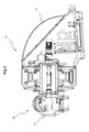
- Fig. 1 is cross sectional view illustrating a general structure of a wind turbine having a generator and a rotor with a single driver sync-pitch-varying mechanism installed therein in accordance with the present invention.
- a typical wind turbine normally comprises two parts, a generator 10 arranged in a nacelle 11 and a rotor 20, which includes a rotor hub 21 and multiple blades (not shown in the figure) equally spaced mounted around the rotor hub 21.
- the single driver sync-pitch-varying mechanism for synchronously varying pitch of this type of multi-blade rotor 20 in accordance with the present invention is accommodated in the rotor hub 21 and the nacelle 11 of the wind turbine 10.
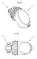
- Figs. 2A and 2B are perspective view and top view of the wind turbine as shown in Fig. 1 .
- Fig.3 is a plan view showing a single driver sync-pitch-varying mechanism 100 of present invention from the top with the generator 10 shown in Fig.1 omitted herein in order to exhibit its structure clearly.
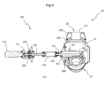
- Fig.4 is a cross-sectional view along a line A-A in Fig.3 illustrating the single driver sync-pitch-varying mechanism of the present invention.
- Fig.5 is an enlarged cross-sectional view illustrating the situation in more detail when the single driver sync-pitch-varying mechanism 100 of the present invention is installed in the wind turbine, wherein a first part of the wind turbine indicated in doted line in the drawing represents the generator 10 of the wind turbine, which includes a generator rotor 12 and a generator stator 13, and a second part of the wind turbine indicated in solid line includes a rotor hub 21 of the rotor 20 and the single driver sync-pitch-varying mechanism 100 accommodated in the rotor hub 21 and the nacelle 11 of the wind turbine 10.
- the rotor hub 21 has multiple fixing openings equally spaced defined there around, each fixing opening is fixed with a bearing seat 22 for corresponding blade to be installed thereto.
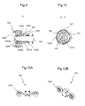
- Fig.6 is a cross sectional view along line B-B in Fig.5 showing the rotor 20 of the wind turbine.
- Fig.7 is a schematic perspective view of the sync-pitch-varying mechanism 100, showing only one bearing seat while the rotor hub 21 being omitted.
- Fig.8 is a schematic perspective view of the sync-pitch-varying mechanism 100 showing the bearing seat 22 in an exploded manner.
- Figs. 5 and 6 clearly show the structural relationship between the bearing seat 22 and the rotor hub 21, while Figs. 7 and 8 shows more clearly the connection between the bearing seat 22 and the sync-pitch-varying mechanism 100.
- Said bearing seat 22 includes a joint flange 221, a bearing 222 and a hood 223.
- One end of the joint flange 221 is fixedly connected with a blade root (not shown) by means of multiple fasteners.
- Another end of the joint flange 221 is fixedly connected with an inner ring of the bearing 222.
- An outer ring of the bearing 222 is fixedly connected with the periphery of the fixing opening.
- the inner ring of the bearing 222 is rotatable with respect to the outer ring of the bearing 222, and thereby allowing the corresponding blade to be rotatable with respective to the rotor hub 21.
- the sync-pitch-varying mechanism 100 of the present invention mainly comprises a driver 110, a transmission 120, a linkage 130, and a control unit.
- Said driver 110 preferably uses a common frequency-variable motor in combination with a planetary gear, also called as the planetary gear motor.
- Said transmission 120 mainly consists of a shaft coupling 121, a ballscrew 122, a supporting structure 123, an intermediate cylinder 124, a driven shaft 125 and a transition cylinder 126.
- Said linkage 130 includes a link hub 131, a guide support 132 and multiple links 133 corresponding to the multiple blades.
- control unit generally includes a speed sensor for measuring speed output from the planetary gear motor, a position sensor for detecting moving position of the intermediate cylinder 124, a switch for shifting spinning orientation of the ballscrew 122, and a programmable controller for controlling rotational speed and orientation of the ballscrew 122 of sync-pitch-varying mechanism 100.
- the driver 110 i.e. the frequency-variable planetary gear motor has an output shaft fixedly connected with respect to a first end of the ballscrew 122 through the shaft coupling 121, therefore the ballscrew 122 is rotatable together with the output shaft of the planetary gear motor.
- the first end portion of the ballscrew 122 is supported by means of the supporting structure 123 provided at a rear end of the generator rotor 12.
- said supporting structure 123 is designed with a double-layer bearing, which takes advantage of the generator rotor 12 as a supporting means to support an end portion of said ballscrew 122 of the transmission 120 in a way that it is not only simplified in the structure but also highly safeguarded in the operation.
- Another end of the ballscrew 122 is connected with a first end of the intermediate cylinder 124 in a screw-and-nut transmission.
- a rotatory motion in either clockwise or anti-clockwise direction output from the ballscrew 122 is firstly transferred to the intermediate cylinder 124 to move the intermediate cylinder 124 with respect to the ballscrew 122 reciprocally through the screw-and-nut transmission between the ballscrew 122 and the intermediate cylinder 124, and then transferred to the driven shaft 125 through the intermediate cylinder 124.
- a first end of the driven shaft 125 is connected to a second end of the intermediate cylinder 124 through the transition cylinder 126 in a way that allows the driven shaft 125 to be only rotatable but not linearly movable in axial direction with respect to the intermediate cylinder 124, of which the detailed structure will be described in the following description with reference to Fig.9 .
- a second end of the driven shaft 125 is connected with front end portions of the link hub 131 and guide support 132 by means of a pin 127 extending through the link hub 131 and guide support 132, of which the detailed structure will be described in the following description with reference to Fig.10 .
- Fig.9 is an enlarged cross sectional view of part I as shown in Fig.5 .
- the first end of a driven shaft 125 is connected to the second end of an intermediate cylinder 124 through the means of the transition cylinder 126.
- Said transition cylinder 126 includes a case having a flange fixedly mounted on the second end of the intermediate cylinder 124 by threaded bolts, a first bearing 1261 and a second bearing 1262 and a third bearing 1263 being sequentially arranged inside of this case, and a first washer 1261a and a second washer 1262a and a third washer 1263a being respectively provided aside the first bearing 1261 and the second bearing 1262 and third bearing 1263.
- a portion of the first end of said driven shaft 125 is designed with two stages.
- a first stage of the driven shaft 125 is extended through a closed end wall of the case of said transition cylinder 126 and retained by the side surface of said first bearing 1261.
- the first end portion of the driven shaft 125 extends throughout the first bearing 1261 and the second bearing 1262 and third bearing 1263 and a cover 1264 provided at a rear opening end of the transition cylinder 126 and extended a short length into the intermediate cylinder 124 and fixed by a screw nut 1265.
- a second stage of the driven shaft 125 is retained by a front side of the screw nut 1265, which is retained by the cover 1264 pressed against the screw nut 1265.
- the driven shaft 125 is connected to the transition cylinder 124 in a way that is rotatable but not linearly movable with respect to the transition cylinder 124, thus the linear motion of the transition cylinder 124 is transferred to the driven shaft 125, so as to move the link hub 131 linearly and simultaneously with rotatory motion about an axis thereof.
- Fig. 10 is an enlarged cross sectional view along line C-C in Fig.5 in order to more clearly show the connection relation between the second end of the driven shaft 125 with the link hub 131, the guide support 132 and the pin 127 of the linkage 130.
- Fig.11A is a front view of the link hub 131
- Fig.11B is a cross sectional view along line D-D in Fig.11A
- Fig.11C is a partial side view from II direction as indicated in Fig.11A showing a front end portion of the link hub 131
- Fig.11D is a cross sectional view along line E-E in Fig.11A showing a bolt hole defined in a connecting end of the link hub 131.
- Said link hub 131 shown in the drawings as an embodiment of the invention is integrally formed with a disc-shaped base 1311, a sleeve 1312 and a pair of connecting lugs 1313 protruded from the sleeve 1312.
- a central axis of each one bolt hole 1316 is substantively parallel to a rotatory central axis of a corresponding bearing 222.
- Said sleeve 1312 has two annual grooves 1314 defined therein at two opposite ends thereof for receiving oil seals in said annual grooves 1314.
- Said two connecting lugs 1313 have two pin holes 1315 respectively defined therein facing towards each other.
- the structure of the guide support 132 is better seen from Fig.12A to Fig.12D .
- Fig.12A is a cross sectional view of the guide support 132.
- Fig.12B is a side view of the guide support of the guide support 132.
- Fig.12C is a cross sectional view along line F-F in Fig.12A of the guide support 132.
- Fig.12D is a perspective view of the guide support 132.
- Said guide support 132 is integrally formed with a fixing base 1321 fixedly mounted at a rear end of the rotor hub 21, and a guide sleeve 1322 extending horizontally from a center of the fixing base 1321 into a middle portion of the rotor hub 21 towards a front end of the rotor hub 21.
- Said guide sleeve 1322 is defined with a pair of elongated guide slots 1323 near a free end thereof corresponding to the two pin holes 1315 on the sleeve 1312 of the link hub 131.
- the guide sleeve 1322 has an end cover 1324 provided at a rear end thereof facing towards the transmission cylinder 124, and a lubricating bearing being provided between said end cover 1324 and the driven shaft 125.
- the pin 127 is inserted through the pin holes 1315 (as seen in Fig.11 ) of the connecting lugs 1313 of the link hub 131, the guide slots 1323 (as seen in Fig.12 ) of the guide sleeve 1322 of the guide support 132, a slide 1325, and a c pin hole defined in the second end of the driven shaft 125 for connection.
- the driven shaft 125 moves linearly along an axial direction together with the pin 127 moving along the elongated guide slots 1323 of the guide sleeve 1322, and therefore, said link hub 131 surrounding said guide sleeve 1322 is carried by said driven shaft 125 to move along the elongated guide slots 1323 of said guide sleeve 1322, in such a way, said the elongated guide slots 1323 functions as a orientation guide to the pin 127 and the link hub 131.
- said driven shaft 125 rotatably functions together with the blades and the rotor hub 21 accompanying said link hub 131, and in the meanwhile said link hub 131 carried by said driven shaft 125 is also linearly movable along said guide sleeve 1322 of the guide support 132 under the driving force output from the frequency-variable planetary gear motor 110.
- each one of said link 133 has two opposite ends which are respectively formed with two link holes 1316.
- a first end of said link 133 is pivotally connected with the disc-shaped base 1311 of the link hub 131 via a first connecting bolt, and a second end of said link 133 is pivotally connected with a connecting block 134 which is fixed to the inner ring 2222 by multiple screws as can be seen in Fig.8 .
- Said link hub 131 is movable in axial direction within a predetermined range which is configured in any applicable instructions or programs via the programmable controller and controlled through the means of the position sensor and the switch, and thus the inner rings 2222 of the bearings 222 is rotatably with respect to the outer rings 2221 of the bearings 222 within a rotabable angle range which is determined as a function of the predetermined movable length range of said link hub 131.
- the frequency-variable planetary gear motor 110 starts running, the driven shaft 125 driven by the motor 110 moves linearly so as to drive said link hub 131 to move along the guide sleeve 1322.
- the speed sensor can be provided aside the gear of the frequency-variable planetary gear motor, as it can be seen from drawings, so that the speed output from this planetary gear motor is measurable by the speed sensor, therefore, a pitch or angle of the blade can be calculated by the controller, and thus the speed output from the frequency-variable planetary gear motor is controllable so as to change the speed of varying of the pitch.
- the position sensor are intended to detect the displacement of the link hub 131, so that the controlling process can be simplified by measuring a displacement of the link hub 131 and determining a target angle range to be changed through an application program embedded in the programmable controller, therefore a high precise control and reliable operation of the sync-pitch-varying mechanism of the present invention are realized.
- the present invention also advantageously provides a mechanism for synchronously varying pitch of a rotor with a self-feathering function. Since the driver of the sync-pitch-varying mechanism of the invention is not only connected to the grid power but also connected to a power supply output of a generator, for instance, a wind generator, the generator provides an on-line type power supply as a backup instead of conventional battery sets to the driver of the sync-pitch-varying mechanism to perform feathering in the case when the grid power is failed. Further, the mechanism for synchronously varying pitch of a rotor of the invention provided with the frequency-variable brake motor is also capable of retaining its pitch angle in operation after an adjustment of the pitch.
- the mechanism for varying pitch of a rotor in accordance with the present invention transforms a rotatory motion output from the single driver to a linear motion of the transmission, through which the linear motion is in turn transmitted to the linkage to move the multiple links synchronously with the link hub of the linkage, and then through the connection between the multiple links and the corresponding multiple bearings, a driving force output from a single driver is transmitted to the multiple bearings to move the inner rings of the bearings with respect to the outer rings of the bearings for pitch varying.
- the transmission and linkage of the inventive mechanism the varying of pitch for the rotor is easily controlled under the control unit with high precision, consistency and reliability.
- the mechanism for varying pitch of a rotor of according to the invention has the advantage that the transmission 120 is accommodated in the nacelle 11, therefore, it is possible to fix those electronic components and circuits for normal detection on static parts in the nacelle 11, and in that only light weight small size mechanical parts of the linkage 130 are fitted in limited internal space of the rotor hub 21, and also in that the ballscrew of the transmission 120 is supported by a double-layer bearing, therefore, the operation reliability and stability of the transmission 120 is secured, and the wiring of the circuit of the control unit is optimized in its safety and stability, and also convenient to be fixed and maintained. Thus the life span of the whole system using this mechanism is prolonged.
Description
- The present invention relates to a pitch-variable rotor being applied in wind generators or hydraulic generators, and more particularly relates to a mechanism for synchronously varying pitch of a multi-blade rotor.
- Along with the rapid growing of economics, energy demand in the industry and our daily life is increasing continuously, while on the other hand the environment protection is facing a tremendous challenge. Since the wind power and hydraulic power are renewable clean power, wind generators and hydraulic generators are more and more applied over the world.
- Rotor blades as key elements for driving rotors of wind or hydraulic generators are very important in that their profile and shape are rather decisive to the efficiency of the power generation. For the sake of sufficiently using the energy and increasing the rate of the power transformation, rotors with pitch-variable technology are now the first preference in the market.
- Presently, one most commonly used conventional type of pitch-variable rotor is to provide each blade with a separate set of pitch varying mechanism, which is synchronously controlled by one controller. Those types of conventional pitch varying mechanisms usually include a servo motor connected with a gearing transmission, and a direct-driven electric cylinder, etc. However, there are still some deficiencies in the conventional pitch varying mechanisms of the rotors as follows.
- Most of those conventional pitch varying mechanisms are designed in a complicated structure with a large size, and therefore not only costly but also not suitable to be installed in small-medium sized generators;
- The energy consumption is big due to their multiple driving manner;
- The operation reliability is low because a rotary joint must be used for cable connection in all kinds of control circuits in the conventional pitch varying mechanism, and therefore it is difficult to ensure the precision of detection in order to control the operation;
The weight and inertia of the rotor of the generator are both increased because many mechanical parts are accommodated inside of the rotor hub, therefore the rate of failure of the blade varying is increased, and the efficiency of the power generation is reduced; - When a system failure occurs, it is difficult to inspect and repair in a short time in those conventional types of pitch varying mechanism ;
- An external power supply is indispensable for those conventional pitch varying mechanisms to perform protective blade reinstatement in case of system halt, therefore there is still a risk when this external power supply fails.
-
EP 2 343 455 A1 describes a wind energy power plant having a rotor blade pitch actuator. The pitch actuator comprises a driving motor. The rotational motion of the driving motor is translated into a translational movement utilized for adjusting the pitch of all rotor blades. The rotor blade pitch actuator is accommodated in the rotor blade hub of the wind energy power plant. - There remains a desire for a wind turbine with a new type of mechanism for synchronously varying pitch of a multi-blade rotor into a simple and compact structure which is easy to be controlled.
- The present invention provides a wind turbine with a new mechanism for synchronously varying pitch of a multi-blade rotor for the purpose of removing all the above mentioned deficiencies and problems of the prior arts. Said mechanism of the present invention employs a single driver to drive a transmission and a linkage in order to perform a sync-pitch-varying of the multiple blades of the rotor. Said single driver sync-pitch-varying mechanism is configured to be suitable in various small-medium-sized multi-blade rotors.
- In particular, the present invention provides a wind turbine including a generator arranged in a nacelle and a new single driver sync-pitch-varying mechanism for a multi-blade rotor having a rotor hub with multiple blades, wherein said multiple blades are equally spaced mounted around said rotor hub through means of corresponding bearing seats, each one of which includes a bearing having an outer ring and an inner ring being rotatably movable with respect to said outer ring. Said mechanism includes a driver, a transmission accommodated in the nacelle, a linkage and a control unit, wherein said transmission includes a shaft coupling, a ballscrew, an intermediate cylinder, a driven shaft and a transition cylinder; said linkage includes a link hub, a guide support and multiple links; said control unit includes a speed sensor, a position sensor, a switch and a programmable controller, characterized in that a rotatory driving force output by said driver through the shaft coupling is transmitted to the driven shaft through a screw-and-nut transmission between the ballscrew and the intermediate cylinder of said transmission so as to drive the driven shaft to move in a linear motion which is then transferred from the driven shaft to the link hub of the linkage through means of the transition cylinder; said controller is configured to enable the driven shaft to move reciprocally within a predefined range of length in order to move the link hub back and forth along the guide support in an axial direction thereof, and therefore said multiple inner rings are rotatably movable in same angle speed synchronously with respect to said corresponding multiple outer rings of said multiple bearing under the driving of the link hub through the corresponding multiple links.
- The single driver sync-pitch-varying mechanism for a multi-blade rotor according to the present invention is capable of simultaneously control pitch varying of multiple blades of a rotor through the means of the transmission and the multiple links of the linkage corresponding to the multiple bearing seats of the multiple blades, thereby driving the link hub of the linkage to move linearly by the single driver so as to simultaneously control pitch varying of the multiple blades of the rotor. Advantageously, the structure of the sync-pitch-varying mechanism of the present invention is simple and compact, and the control of the sync-pitch-varying mechanism for the multi-blade rotor is precise, consistent and highly reliable.
- The above and other objects and features of the invention will now be described in detail according to the embodiments, and the concept and thought of the technical features and effectiveness of the present invention will become apparent from the following detailed description considered in conjunction with the accompanying drawings.
-
-
Fig.1 is a cross sectional view of a wind turbine including a generator and a rotor provided with a sync-pitch-varying mechanism according to the present invention; -
Fig.2A is a perspective view of the wind turbine as shown inFig. 1 ; -
Fig.2B is a top view of the wind turbine as shown inFig. 1 ; -
Fig.3 is a top view showing the sync-pitch-varying mechanism installed in the wind turbine with a main part of the generator omitted; -
Fig.4 is a cross sectional view along line A-A inFig.3 showing the sync-pitch-varying mechanism in accordance with the present invention; -
Fig.5 is an enlarged schematic cross-sectional view showing the sync-pitch-varying mechanism installed in the wind turbine in accordance with the present invention; -
Fig.6 is a cross sectional view along line B-B inFig.5 showing the sync-pitch-varying mechanism in accordance with the present invention; -
Fig.7 is a schematic perspective view of the sync-pitch-varying mechanism in accordance with the present invention, showing only one bearing seat; -
Fig.8 is a schematic perspective view of the sync-pitch-varying mechanism in accordance with the present invention, showing one bearing seat in an exploded manner; -
Fig.9 is an enlarged cross sectional view of part I as indicated inFig.5 , showing a connection between a first end of a driven shaft and a second end of an intermediate cylinder in a transmission of the sync-pitch-varying mechanism according to the present invention; -
Fig.10 is a cross sectional view along line C-C inFig.5 showing a connection between a second end of the driven shaft and a link hub and a guide support of the linkage of the present invention; -
Fig.11A is a front view showing a link hub of the linkage in accordance with the embodiment of the invention; -
Fig.11B is a cross sectional view along line D-D inFig.11A showing the link hub of the linkage in accordance with the embodiment of the invention; -
Fig.11C is a partial side view from II direction as indicated inFig.11A showing a connecting lug of the link hub of the linkage in accordance with the embodiment of the invention; -
Fig.11D is a cross sectional view along line E-E inFig.11A showing the link hub of the linkage in accordance with the embodiment of the invention; -
Fig.12A is a cross sectional view showing an embodiment of a guide support of the linkage in accordance with the present invention; -
Fig.12B is a side view showing the embodiment of the guide support of the linkage in accordance with the present invention; -
Fig.12C is a cross sectional view along line F-F inFig. 12A showing the embodiment of the guide support of the linkage in accordance with the present invention; -
Fig.12D is a perspective view showing the embodiment of the guide support of the linkage in accordance with the present invention; -
Fig.13A is a schematic side view with a partial cross section showing an embodiment of a link of the linkage in accordance with the present invention; and -
Fig.13B is a perspective view showing the embodiment of the link of the linkage in accordance with the present invention. - Now the present invention will be described in detail in conjunction with embodiments as illustrated in the accompanying drawings. Since the pitch varying technology is applicable in various rotors, such as rotors of wind or water turbine and helicopter etc., the present invention first relates to a mechanism for synchronously varying pitch of a rotor applicable in various technology domains. It is understandable that the following description of an embodiment of a single driver sync-pitch-varying mechanism is only one practical application of the present invention as for exemplary illustrating the mechanism and the principle of the invention, but not for limitation of the protection scope of the invention.
-
Fig. 1 is cross sectional view illustrating a general structure of a wind turbine having a generator and a rotor with a single driver sync-pitch-varying mechanism installed therein in accordance with the present invention. A typical wind turbine normally comprises two parts, agenerator 10 arranged in anacelle 11 and arotor 20, which includes arotor hub 21 and multiple blades (not shown in the figure) equally spaced mounted around therotor hub 21. The single driver sync-pitch-varying mechanism for synchronously varying pitch of this type ofmulti-blade rotor 20 in accordance with the present invention is accommodated in therotor hub 21 and thenacelle 11 of thewind turbine 10.Figs. 2A and 2B are perspective view and top view of the wind turbine as shown inFig. 1 . -
Fig.3 is a plan view showing a single driver sync-pitch-varying mechanism 100 of present invention from the top with thegenerator 10 shown inFig.1 omitted herein in order to exhibit its structure clearly.Fig.4 is a cross-sectional view along a line A-A inFig.3 illustrating the single driver sync-pitch-varying mechanism of the present invention. Further,Fig.5 is an enlarged cross-sectional view illustrating the situation in more detail when the single driver sync-pitch-varying mechanism 100 of the present invention is installed in the wind turbine, wherein a first part of the wind turbine indicated in doted line in the drawing represents thegenerator 10 of the wind turbine, which includes a generator rotor 12 and a generator stator 13, and a second part of the wind turbine indicated in solid line includes arotor hub 21 of therotor 20 and the single driver sync-pitch-varying mechanism 100 accommodated in therotor hub 21 and thenacelle 11 of thewind turbine 10. Therotor hub 21 has multiple fixing openings equally spaced defined there around, each fixing opening is fixed with a bearingseat 22 for corresponding blade to be installed thereto. - The detailed structure of said bearing
seat 22 can be shown more apparently with reference toFigs. 6 ,7 and8 .Fig.6 is a cross sectional view along line B-B inFig.5 showing therotor 20 of the wind turbine.Fig.7 is a schematic perspective view of the sync-pitch-varyingmechanism 100, showing only one bearing seat while therotor hub 21 being omitted.Fig.8 is a schematic perspective view of the sync-pitch-varyingmechanism 100 showing the bearingseat 22 in an exploded manner.Figs. 5 and6 clearly show the structural relationship between the bearingseat 22 and therotor hub 21, whileFigs. 7 and8 shows more clearly the connection between the bearingseat 22 and the sync-pitch-varyingmechanism 100. Said bearingseat 22 includes ajoint flange 221, abearing 222 and ahood 223. One end of thejoint flange 221 is fixedly connected with a blade root (not shown) by means of multiple fasteners. Another end of thejoint flange 221 is fixedly connected with an inner ring of thebearing 222. An outer ring of thebearing 222 is fixedly connected with the periphery of the fixing opening. The inner ring of thebearing 222 is rotatable with respect to the outer ring of thebearing 222, and thereby allowing the corresponding blade to be rotatable with respective to therotor hub 21. - With reference to
Fig.5 ,Figs. 7 and8 , the sync-pitch-varyingmechanism 100 of the present invention mainly comprises adriver 110, atransmission 120, alinkage 130, and a control unit. Saiddriver 110 preferably uses a common frequency-variable motor in combination with a planetary gear, also called as the planetary gear motor. Saidtransmission 120 mainly consists of ashaft coupling 121, aballscrew 122, a supportingstructure 123, anintermediate cylinder 124, a drivenshaft 125 and atransition cylinder 126.Said linkage 130 includes alink hub 131, aguide support 132 andmultiple links 133 corresponding to the multiple blades. Further, the control unit generally includes a speed sensor for measuring speed output from the planetary gear motor, a position sensor for detecting moving position of theintermediate cylinder 124, a switch for shifting spinning orientation of theballscrew 122, and a programmable controller for controlling rotational speed and orientation of theballscrew 122 of sync-pitch-varyingmechanism 100. - In particular, the
driver 110, i.e. the frequency-variable planetary gear motor has an output shaft fixedly connected with respect to a first end of the ballscrew 122 through theshaft coupling 121, therefore theballscrew 122 is rotatable together with the output shaft of the planetary gear motor. It can be seen fromFig.1 that the first end portion of theballscrew 122 is supported by means of the supportingstructure 123 provided at a rear end of the generator rotor 12. Preferably, said supportingstructure 123 is designed with a double-layer bearing, which takes advantage of the generator rotor 12 as a supporting means to support an end portion of saidballscrew 122 of thetransmission 120 in a way that it is not only simplified in the structure but also highly safeguarded in the operation. Another end of theballscrew 122 is connected with a first end of theintermediate cylinder 124 in a screw-and-nut transmission. A rotatory motion in either clockwise or anti-clockwise direction output from theballscrew 122 is firstly transferred to theintermediate cylinder 124 to move theintermediate cylinder 124 with respect to theballscrew 122 reciprocally through the screw-and-nut transmission between the ballscrew 122 and theintermediate cylinder 124, and then transferred to the drivenshaft 125 through theintermediate cylinder 124. A first end of the drivenshaft 125 is connected to a second end of theintermediate cylinder 124 through thetransition cylinder 126 in a way that allows the drivenshaft 125 to be only rotatable but not linearly movable in axial direction with respect to theintermediate cylinder 124, of which the detailed structure will be described in the following description with reference toFig.9 . A second end of the drivenshaft 125 is connected with front end portions of thelink hub 131 and guidesupport 132 by means of apin 127 extending through thelink hub 131 and guidesupport 132, of which the detailed structure will be described in the following description with reference toFig.10 . -
Fig.9 is an enlarged cross sectional view of part I as shown inFig.5 . The first end of a drivenshaft 125 is connected to the second end of anintermediate cylinder 124 through the means of thetransition cylinder 126. Saidtransition cylinder 126 includes a case having a flange fixedly mounted on the second end of theintermediate cylinder 124 by threaded bolts, afirst bearing 1261 and asecond bearing 1262 and athird bearing 1263 being sequentially arranged inside of this case, and afirst washer 1261a and asecond washer 1262a and athird washer 1263a being respectively provided aside thefirst bearing 1261 and thesecond bearing 1262 andthird bearing 1263. A portion of the first end of said drivenshaft 125 is designed with two stages. A first stage of the drivenshaft 125 is extended through a closed end wall of the case of saidtransition cylinder 126 and retained by the side surface of saidfirst bearing 1261. The first end portion of the drivenshaft 125 extends throughout thefirst bearing 1261 and thesecond bearing 1262 andthird bearing 1263 and acover 1264 provided at a rear opening end of thetransition cylinder 126 and extended a short length into theintermediate cylinder 124 and fixed by ascrew nut 1265. A second stage of the drivenshaft 125 is retained by a front side of thescrew nut 1265, which is retained by thecover 1264 pressed against thescrew nut 1265. Therefore, the drivenshaft 125 is connected to thetransition cylinder 124 in a way that is rotatable but not linearly movable with respect to thetransition cylinder 124, thus the linear motion of thetransition cylinder 124 is transferred to the drivenshaft 125, so as to move thelink hub 131 linearly and simultaneously with rotatory motion about an axis thereof. -
Fig. 10 is an enlarged cross sectional view along line C-C inFig.5 in order to more clearly show the connection relation between the second end of the drivenshaft 125 with thelink hub 131, theguide support 132 and thepin 127 of thelinkage 130. - The structure of the
link hub 131 is better shown inFig.11A to Fig.11D. Fig.11A is a front view of thelink hub 131,Fig.11B is a cross sectional view along line D-D inFig.11A, Fig.11C is a partial side view from II direction as indicated inFig.11A showing a front end portion of thelink hub 131, andFig.11D is a cross sectional view along line E-E inFig.11A showing a bolt hole defined in a connecting end of thelink hub 131. Saidlink hub 131 shown in the drawings as an embodiment of the invention is integrally formed with a disc-shapedbase 1311, asleeve 1312 and a pair of connectinglugs 1313 protruded from thesleeve 1312. There aremultiple bolt holes 1316 defined in side surface of the disc-shapedbase 1311 corresponding to the multiple the blades. A central axis of each onebolt hole 1316 is substantively parallel to a rotatory central axis of acorresponding bearing 222. Saidsleeve 1312 has twoannual grooves 1314 defined therein at two opposite ends thereof for receiving oil seals in saidannual grooves 1314. Said two connectinglugs 1313 have twopin holes 1315 respectively defined therein facing towards each other. - The structure of the
guide support 132 is better seen fromFig.12A to Fig.12D . -
Fig.12A is a cross sectional view of theguide support 132.Fig.12B is a side view of the guide support of theguide support 132.Fig.12C is a cross sectional view along line F-F inFig.12A of theguide support 132.Fig.12D is a perspective view of theguide support 132. Saidguide support 132 is integrally formed with afixing base 1321 fixedly mounted at a rear end of therotor hub 21, and aguide sleeve 1322 extending horizontally from a center of thefixing base 1321 into a middle portion of therotor hub 21 towards a front end of therotor hub 21. Saidguide sleeve 1322 is defined with a pair ofelongated guide slots 1323 near a free end thereof corresponding to the twopin holes 1315 on thesleeve 1312 of thelink hub 131. - The
guide sleeve 1322 has anend cover 1324 provided at a rear end thereof facing towards thetransmission cylinder 124, and a lubricating bearing being provided between saidend cover 1324 and the drivenshaft 125. - Now returning back to
Fig.10 and with reference toFigs. 7 and8 , thepin 127 is inserted through the pin holes 1315 (as seen inFig.11 ) of the connectinglugs 1313 of thelink hub 131, the guide slots 1323 (as seen inFig.12 ) of theguide sleeve 1322 of theguide support 132, aslide 1325, and a c pin hole defined in the second end of the drivenshaft 125 for connection. Thus, the drivenshaft 125 moves linearly along an axial direction together with thepin 127 moving along theelongated guide slots 1323 of theguide sleeve 1322, and therefore, saidlink hub 131 surrounding saidguide sleeve 1322 is carried by said drivenshaft 125 to move along theelongated guide slots 1323 of saidguide sleeve 1322, in such a way, said theelongated guide slots 1323 functions as a orientation guide to thepin 127 and thelink hub 131. Therefore, through the above described structure, said drivenshaft 125 rotatably functions together with the blades and therotor hub 21 accompanying saidlink hub 131, and in the meanwhile saidlink hub 131 carried by said drivenshaft 125 is also linearly movable along saidguide sleeve 1322 of theguide support 132 under the driving force output from the frequency-variableplanetary gear motor 110. - The above described
linkage 130 according to the invention is operatively connected to theinner rings 2222 of themultiple bearings 222 via the correspondingmultiple links 133, the structure of which are illustrated in a front side view as shown inFig.13A and a perspective view as shown inFig.13B . Specially, as referred toFig.5 to Fig.8 , each one of saidlink 133 has two opposite ends which are respectively formed with two link holes 1316. A first end of saidlink 133 is pivotally connected with the disc-shapedbase 1311 of thelink hub 131 via a first connecting bolt, and a second end of saidlink 133 is pivotally connected with a connectingblock 134 which is fixed to theinner ring 2222 by multiple screws as can be seen inFig.8 . - Now referring to
Figs. 7 and8 , the working principle of the single driver sync-pitch-varying mechanism of multi-blade rotor of the present invention will be introduced. When the motor of thedriver 110 starts running, a rotatory motion output through the gear from the frequency-variable planetary gear motor is transmitted to a linear motion of the drivenshaft 125 through thetransmission 124, thus thelink hub 131 carried by the drivenshaft 125 moves linearly in axial direction along theguide sleeve 1322. Saidlink hub 131 is movable in axial direction within a predetermined range which is configured in any applicable instructions or programs via the programmable controller and controlled through the means of the position sensor and the switch, and thus theinner rings 2222 of thebearings 222 is rotatably with respect to theouter rings 2221 of thebearings 222 within a rotabable angle range which is determined as a function of the predetermined movable length range of saidlink hub 131. Through the above described mechanism, when the rotor is spinning, the drivenshaft 125 driven by thepin 127 is also spinning along with the rotor, when the driver, i.e. the frequency-variableplanetary gear motor 110 starts running, the drivenshaft 125 driven by themotor 110 moves linearly so as to drive saidlink hub 131 to move along theguide sleeve 1322. The speed sensor can be provided aside the gear of the frequency-variable planetary gear motor, as it can be seen from drawings, so that the speed output from this planetary gear motor is measurable by the speed sensor, therefore, a pitch or angle of the blade can be calculated by the controller, and thus the speed output from the frequency-variable planetary gear motor is controllable so as to change the speed of varying of the pitch. According to the present invention, the position sensor are intended to detect the displacement of thelink hub 131, so that the controlling process can be simplified by measuring a displacement of thelink hub 131 and determining a target angle range to be changed through an application program embedded in the programmable controller, therefore a high precise control and reliable operation of the sync-pitch-varying mechanism of the present invention are realized. - In addition, the present invention also advantageously provides a mechanism for synchronously varying pitch of a rotor with a self-feathering function. Since the driver of the sync-pitch-varying mechanism of the invention is not only connected to the grid power but also connected to a power supply output of a generator, for instance, a wind generator, the generator provides an on-line type power supply as a backup instead of conventional battery sets to the driver of the sync-pitch-varying mechanism to perform feathering in the case when the grid power is failed. Further, the mechanism for synchronously varying pitch of a rotor of the invention provided with the frequency-variable brake motor is also capable of retaining its pitch angle in operation after an adjustment of the pitch.
- In summary, the mechanism for varying pitch of a rotor in accordance with the present invention transforms a rotatory motion output from the single driver to a linear motion of the transmission, through which the linear motion is in turn transmitted to the linkage to move the multiple links synchronously with the link hub of the linkage, and then through the connection between the multiple links and the corresponding multiple bearings, a driving force output from a single driver is transmitted to the multiple bearings to move the inner rings of the bearings with respect to the outer rings of the bearings for pitch varying. Advantageously, by taking advantage of one single driver, the transmission and linkage of the inventive mechanism, the varying of pitch for the rotor is easily controlled under the control unit with high precision, consistency and reliability.
- The mechanism for varying pitch of a rotor of according to the invention has the advantage that the
transmission 120 is accommodated in thenacelle 11, therefore, it is possible to fix those electronic components and circuits for normal detection on static parts in thenacelle 11, and in that only light weight small size mechanical parts of thelinkage 130 are fitted in limited internal space of therotor hub 21, and also in that the ballscrew of thetransmission 120 is supported by a double-layer bearing, therefore, the operation reliability and stability of thetransmission 120 is secured, and the wiring of the circuit of the control unit is optimized in its safety and stability, and also convenient to be fixed and maintained. Thus the life span of the whole system using this mechanism is prolonged. - Although the foregoing examples which have already been illustrated as preferred embodiments of present invention, those people who are skilled in the art may better understand that any possible changes, modifications and amendments for carrying out the same purpose of the present invention are readily perceivable under the teaching of this invention.
Claims (8)
- A wind turbine including a generator (10) arranged in a nacelle (11) and a mechanism for synchronously varying the pitch of a multi-blade rotor (20) having a rotor hub (21) with multiple blades, wherein said multiple blades are equally-spaced mounted around said rotor hub (21) through means of corresponding bearing seats (22), each one of which includes a bearing (222) having an outer ring (2221) and an inner ring (2222) being rotatably movable with respect to said outer ring (2221), characterized in that
said mechanism includes a driver (110), a transmission (120) being accommodated in the nacelle (11), a linkage (130), and a control unit; wherein said transmission (120) includes a shaft coupling (121), a ballscrew (122), an intermediate cylinder (124), a driven shaft (125) and a transition cylinder (126);
said linkage (130) includes a link hub (131), a guide support (132) and multiple links (133);
said control unit includes a speed sensor, a position sensor, a switch and a programmable controller,
a rotatory driving force output by said driver (110) through the shaft coupling (121) is transmitted to the driven shaft (125) through a screw-and-nut transmission between the ballscrew (122) and the intermediate cylinder (124) of said transmission (120) so as to drive the driven shaft (125) to move in a linear motion which is then transferred from the driven shaft (125) to the link hub (131) of the linkage (130) through means of the transition cylinder (126);
said controller is configured to enable the driven shaft (125) to move reciprocally within a predefined range of length in order to move the link hub (131) back and forth along the guide support (132) in an axial direction thereof, and therefore
said multiple inner rings (2222) are rotatably movable in same angle speed synchronously with respect to said corresponding multiple outer rings (2221) of said multiple bearing (222) under the driving of the link hub (131) through the corresponding multiple links (133). - The wind turbine as claimed in claim 1, characterized in that said transmission (120) further includes a supporting structure (123) with a double-layer bearing for supporting the ballscrew (122).
- The wind turbine as claimed in claim 1, characterized in that the link hub (131) is integrally formed with a disc-shaped base (1311) and a sleeve (1312) extending therefrom, wherein a pair of connecting lugs (1313) are protruded from a front end of said sleeve (1312) and respectively defined with two pin holes (1315) therein opposite to the each other.
- The wind turbine as claimed in claim 3, characterized in that two annual grooves (1314) are respectively defined in an inner surface of said sleeve (1312) of said link hub (131) near two opposite ends thereof for receiving oil seal therein.
- The wind turbine as claimed in claim 3, characterized in that said base (1311) of the link hub (131) has multiple screw holes (1316) defined there around in equal space corresponding to the multiple blades, each said screw hole (1316) has a central axis extending substantively parallel to a central axis of a corresponding bearing (222).
- The wind turbine as claimed in claim 1, characterized in that said guide support (132) is integrally formed with a base (1321) and a guide sleeve (1322), wherein a free end of said guide sleeve (1322) extending from the base (1321) into the rotor hub (21) is defined with a pair of guide slots (1323) opposite to the each other.
- The wind turbine as claimed in claim 1, characterized in that a first end of said driven shaft (125) is rotatably connected with said intermediate cylinder (124) but not movably with respect to said intermediate cylinder (124) in an axial direction thereof.
- The wind turbine as claimed in claim 7, characterized in that the first end of said driven shaft (125) is connected with said intermediate cylinder (124) through said transition cylinder (126), which has a first, second and third bearings (1261, 1262, 1263) arranged therein in sequence, and a first, second and third washers (1261a, 1262a, 1263a) provided aside said corresponding first, second and third bearings (1261, 1262, 1263), respectively, a portion of the first end of said driven shaft (125) is configured in two stages, a first stage extending through a closed end wall of said transition cylinder (126) and being retained by a side of said first bearing (1261), a second stage extending throughout the first, second, third bearings (1261, 1262, 1263) and a cover (1264) into the intermediate cylinder (124) and then being fastened by a screw nut (1265) so as to be retained by a side of said screw nut (1265), which is retained against the cover (1264).
Priority Applications (1)
| Application Number | Priority Date | Filing Date | Title |
|---|---|---|---|
| PL11852207T PL2597304T3 (en) | 2011-09-02 | 2011-09-02 | Wind turbine with a mechanism for synchronously varying the pitch of a multi-blade rotor |
Applications Claiming Priority (1)
| Application Number | Priority Date | Filing Date | Title |
|---|---|---|---|
| PCT/CN2011/079295 WO2013029277A1 (en) | 2011-09-02 | 2011-09-02 | Multi-blade single-drive synchronous pitch-changing device |
Publications (3)
| Publication Number | Publication Date |
|---|---|
| EP2597304A1 EP2597304A1 (en) | 2013-05-29 |
| EP2597304A4 EP2597304A4 (en) | 2013-11-13 |
| EP2597304B1 true EP2597304B1 (en) | 2015-05-27 |
Family
ID=46950457
Family Applications (1)
| Application Number | Title | Priority Date | Filing Date |
|---|---|---|---|
| EP11852207.7A Active EP2597304B1 (en) | 2011-09-02 | 2011-09-02 | Wind turbine with a mechanism for synchronously varying the pitch of a multi-blade rotor |
Country Status (5)
| Country | Link |
|---|---|
| US (1) | US9322284B2 (en) |
| EP (1) | EP2597304B1 (en) |
| DK (1) | DK2597304T3 (en) |
| PL (1) | PL2597304T3 (en) |
| WO (1) | WO2013029277A1 (en) |
Families Citing this family (10)
| Publication number | Priority date | Publication date | Assignee | Title |
|---|---|---|---|---|
| EP2597304B1 (en) | 2011-09-02 | 2015-05-27 | Shanghai Ghrepower Green Energy Co., Ltd. | Wind turbine with a mechanism for synchronously varying the pitch of a multi-blade rotor |
| ES2435340B1 (en) * | 2012-06-15 | 2014-12-05 | Gamesa Innovation & Technology, S.L. | Fixing system for wind turbines and method of placement |
| CN103670920B (en) * | 2012-09-06 | 2016-06-01 | 台达电子工业股份有限公司 | The blade zero point backup of wind-driven variable pitch system and wind-driven variable pitch system and restoration methods |
| ITVR20130105A1 (en) * | 2013-05-03 | 2014-11-04 | Treccani Engineering S R L | WIND TURBINE |
| PL225683B1 (en) * | 2014-07-31 | 2017-05-31 | Ząber Zdzisław Przedsiębiorstwo Produkcyjno Usługowe Dr Ząber | Method for the wind power station control and the wind power station control system |
| US20180023543A1 (en) * | 2015-03-30 | 2018-01-25 | Vestas Wind Systems A/S | A wind turbine comprising two or more rotors |
| BR112017019060A2 (en) * | 2015-03-30 | 2018-04-17 | Vestas Wind Sys As | wind turbine with a rotor comprising a hollow king pin |
| DE102015105249B3 (en) * | 2015-04-07 | 2016-09-29 | Technische Universität Berlin | Rotor and method for adjusting a blade pitch of a rotor blade on the rotor |
| EP3845760A1 (en) * | 2019-12-31 | 2021-07-07 | Nordex Energy Spain, S.A.U. | Pitch bearing of a wind turbine, wind turbine and method of limiting the stresses in the reinforcement plates of a pitch bearing |
| CN115750207B (en) * | 2022-11-24 | 2024-02-20 | 华能四平风力发电有限公司 | Overspeed yaw prevention lifting device for wind turbine generator |
Family Cites Families (16)
| Publication number | Priority date | Publication date | Assignee | Title |
|---|---|---|---|---|
| US4183715A (en) * | 1978-02-01 | 1980-01-15 | First National Bank Of Lubbock | Adjustable vane windmills |
| US4490093A (en) * | 1981-07-13 | 1984-12-25 | U.S. Windpower, Inc. | Windpower system |
| US4435646A (en) | 1982-02-24 | 1984-03-06 | North Wind Power Company, Inc. | Wind turbine rotor control system |
| US4623051A (en) * | 1984-05-02 | 1986-11-18 | Roton Products, Inc. | Load bearing, one-way, spring clutch assembly |
| JP3581918B2 (en) * | 1998-08-21 | 2004-10-27 | 東洋機械金属株式会社 | Nozzle touch mechanism of injection molding machine |
| KR100306208B1 (en) * | 1998-09-16 | 2001-12-20 | 조한원 | Wing angle control apparatus of rotatable body |
| JP2000145914A (en) * | 1998-11-17 | 2000-05-26 | Tsubakimoto Chain Co | Bearing linear actuator with backstop mechanism |
| JP2001120599A (en) * | 1999-10-29 | 2001-05-08 | Nissan Shatai Co Ltd | Seat lifter |
| EP1719812B1 (en) * | 2004-02-09 | 2018-04-04 | NTN Corporation | Grease |
| CN101037988A (en) | 2006-03-16 | 2007-09-19 | 沈阳风电设备发展有限责任公司 | Wind-driven generator variable propeller pitch device |
| NZ555848A (en) | 2007-06-12 | 2010-04-30 | Storm Rider Holdings Ltd | Improved wind generator |
| CN201334986Y (en) * | 2008-10-23 | 2009-10-28 | 宁波欣达(集团)有限公司 | Propeller pitch adjusting mechanism of wind-power generator |
| EP2343455A1 (en) * | 2010-01-07 | 2011-07-13 | Vestas Wind Systems A/S | Wind energy power plant having a rotor blade pitch actuator |
| CN201881049U (en) * | 2010-11-09 | 2011-06-29 | 苏州德龙激光有限公司 | Laser spiral rotation optical module applied to laser processing device |
| CN201953567U (en) | 2011-03-29 | 2011-08-31 | 三一电气有限责任公司 | Wind generating set and pitch-regulating mechanism thereof |
| EP2597304B1 (en) | 2011-09-02 | 2015-05-27 | Shanghai Ghrepower Green Energy Co., Ltd. | Wind turbine with a mechanism for synchronously varying the pitch of a multi-blade rotor |
-
2011
- 2011-09-02 EP EP11852207.7A patent/EP2597304B1/en active Active
- 2011-09-02 PL PL11852207T patent/PL2597304T3/en unknown
- 2011-09-02 DK DK11852207.7T patent/DK2597304T3/en active
- 2011-09-02 WO PCT/CN2011/079295 patent/WO2013029277A1/en active Application Filing
- 2011-09-02 US US13/520,733 patent/US9322284B2/en active Active
Also Published As
| Publication number | Publication date |
|---|---|
| CN102725519A (en) | 2012-10-10 |
| EP2597304A1 (en) | 2013-05-29 |
| US9322284B2 (en) | 2016-04-26 |
| WO2013029277A1 (en) | 2013-03-07 |
| US20130216380A1 (en) | 2013-08-22 |
| DK2597304T3 (en) | 2015-08-31 |
| PL2597304T3 (en) | 2015-12-31 |
| EP2597304A4 (en) | 2013-11-13 |
Similar Documents
| Publication | Publication Date | Title |
|---|---|---|
| EP2597304B1 (en) | Wind turbine with a mechanism for synchronously varying the pitch of a multi-blade rotor | |
| CA2560815C (en) | Actuator for adjusting a rotor blade pitch angle | |
| CN101927497B (en) | Rotating and swinging joint module of robot of single degree of freedom | |
| EP3296564B1 (en) | Drive device for wind turbines, drive device unit for wind turbines, and wind turbine | |
| US9683553B2 (en) | System and method for monitoring wind turbine loading | |
| EP2886858B2 (en) | Wind turbine with blade pitch system | |
| RU2523515C2 (en) | Device for moving power cylinder for control over turboprop fan vanes | |
| CN101913150B (en) | Robot revolute joint module with single degree of freedom | |
| JP6832237B2 (en) | Bicycle electric derailleur | |
| KR20140072561A (en) | Rotor shaft locking apparatus for wind power generator | |
| US20100296927A1 (en) | Eolic turbine and adjusting device of the blade pitch | |
| US20140369836A1 (en) | Turbine with hydraulic variable pitch system | |
| CN203847326U (en) | Electric direct-driven wind power variable pitch device | |
| US9410531B2 (en) | Wind turbine generator | |
| JP7146580B2 (en) | Wind power generator and wind power generation system | |
| CN103953504B (en) | Electric direct-driven type wind power variable-pitch device | |
| CN108869190B (en) | Electric barring gear for wind generating set | |
| JPH04101074A (en) | Windmill | |
| CN104534041A (en) | Electric execution device of dual-redundancy direct-drive type roller lead screw pair | |
| CN101978170B (en) | Device for changing a pitch of a blade of an impeller/propeller and a fan comprising the device | |
| ITCO20100049A1 (en) | CENTERING DEVICE AND GUIDE RING SYSTEM | |
| IES20090973A2 (en) | A wind turbine blade assembly | |
| CN101907515B (en) | Fully-digital functional experiment table of electric variable pitch system | |
| CN104128903A (en) | Quick nut dismantling mechanism | |
| KR101505435B1 (en) | Wind power generator |
Legal Events
| Date | Code | Title | Description |
|---|---|---|---|
| PUAI | Public reference made under article 153(3) epc to a published international application that has entered the european phase |
Free format text: ORIGINAL CODE: 0009012 |
|
| 17P | Request for examination filed |
Effective date: 20120816 |
|
| AK | Designated contracting states |
Kind code of ref document: A1 Designated state(s): AL AT BE BG CH CY CZ DE DK EE ES FI FR GB GR HR HU IE IS IT LI LT LU LV MC MK MT NL NO PL PT RO RS SE SI SK SM TR |
|
| RAP1 | Party data changed (applicant data changed or rights of an application transferred) |
Owner name: SHANGHAI GHREPOWER GREEN ENERGY CO., LTD. |
|
| A4 | Supplementary search report drawn up and despatched |
Effective date: 20131014 |
|
| RIC1 | Information provided on ipc code assigned before grant |
Ipc: F03D 7/02 20060101AFI20131008BHEP |
|
| GRAP | Despatch of communication of intention to grant a patent |
Free format text: ORIGINAL CODE: EPIDOSNIGR1 |
|
| DAX | Request for extension of the european patent (deleted) | ||
| INTG | Intention to grant announced |
Effective date: 20140825 |
|
| GRAP | Despatch of communication of intention to grant a patent |
Free format text: ORIGINAL CODE: EPIDOSNIGR1 |
|
| INTG | Intention to grant announced |
Effective date: 20150108 |
|
| GRAS | Grant fee paid |
Free format text: ORIGINAL CODE: EPIDOSNIGR3 |
|
| GRAA | (expected) grant |
Free format text: ORIGINAL CODE: 0009210 |
|
| AK | Designated contracting states |
Kind code of ref document: B1 Designated state(s): AL AT BE BG CH CY CZ DE DK EE ES FI FR GB GR HR HU IE IS IT LI LT LU LV MC MK MT NL NO PL PT RO RS SE SI SK SM TR |
|
| REG | Reference to a national code |
Ref country code: GB Ref legal event code: FG4D |
|
| REG | Reference to a national code |
Ref country code: CH Ref legal event code: EP |
|
| REG | Reference to a national code |
Ref country code: AT Ref legal event code: REF Ref document number: 729007 Country of ref document: AT Kind code of ref document: T Effective date: 20150615 |
|
| REG | Reference to a national code |
Ref country code: IE Ref legal event code: FG4D |
|
| REG | Reference to a national code |
Ref country code: DE Ref legal event code: R096 Ref document number: 602011016849 Country of ref document: DE |
|
| REG | Reference to a national code |
Ref country code: DK Ref legal event code: T3 Effective date: 20150827 |
|
| REG | Reference to a national code |
Ref country code: NO Ref legal event code: T2 Effective date: 20150527 Ref country code: LT Ref legal event code: MG4D |
|
| PG25 | Lapsed in a contracting state [announced via postgrant information from national office to epo] |
Ref country code: ES Free format text: LAPSE BECAUSE OF FAILURE TO SUBMIT A TRANSLATION OF THE DESCRIPTION OR TO PAY THE FEE WITHIN THE PRESCRIBED TIME-LIMIT Effective date: 20150527 Ref country code: PT Free format text: LAPSE BECAUSE OF FAILURE TO SUBMIT A TRANSLATION OF THE DESCRIPTION OR TO PAY THE FEE WITHIN THE PRESCRIBED TIME-LIMIT Effective date: 20150928 Ref country code: HR Free format text: LAPSE BECAUSE OF FAILURE TO SUBMIT A TRANSLATION OF THE DESCRIPTION OR TO PAY THE FEE WITHIN THE PRESCRIBED TIME-LIMIT Effective date: 20150527 Ref country code: LT Free format text: LAPSE BECAUSE OF FAILURE TO SUBMIT A TRANSLATION OF THE DESCRIPTION OR TO PAY THE FEE WITHIN THE PRESCRIBED TIME-LIMIT Effective date: 20150527 |
|
| REG | Reference to a national code |
Ref country code: NL Ref legal event code: MP Effective date: 20150527 |
|
| PG25 | Lapsed in a contracting state [announced via postgrant information from national office to epo] |
Ref country code: LV Free format text: LAPSE BECAUSE OF FAILURE TO SUBMIT A TRANSLATION OF THE DESCRIPTION OR TO PAY THE FEE WITHIN THE PRESCRIBED TIME-LIMIT Effective date: 20150527 Ref country code: GR Free format text: LAPSE BECAUSE OF FAILURE TO SUBMIT A TRANSLATION OF THE DESCRIPTION OR TO PAY THE FEE WITHIN THE PRESCRIBED TIME-LIMIT Effective date: 20150828 Ref country code: RS Free format text: LAPSE BECAUSE OF FAILURE TO SUBMIT A TRANSLATION OF THE DESCRIPTION OR TO PAY THE FEE WITHIN THE PRESCRIBED TIME-LIMIT Effective date: 20150527 Ref country code: BG Free format text: LAPSE BECAUSE OF FAILURE TO SUBMIT A TRANSLATION OF THE DESCRIPTION OR TO PAY THE FEE WITHIN THE PRESCRIBED TIME-LIMIT Effective date: 20150827 Ref country code: IS Free format text: LAPSE BECAUSE OF FAILURE TO SUBMIT A TRANSLATION OF THE DESCRIPTION OR TO PAY THE FEE WITHIN THE PRESCRIBED TIME-LIMIT Effective date: 20150927 |
|
| REG | Reference to a national code |
Ref country code: PL Ref legal event code: T3 |
|
| PG25 | Lapsed in a contracting state [announced via postgrant information from national office to epo] |
Ref country code: EE Free format text: LAPSE BECAUSE OF FAILURE TO SUBMIT A TRANSLATION OF THE DESCRIPTION OR TO PAY THE FEE WITHIN THE PRESCRIBED TIME-LIMIT Effective date: 20150527 |
|
| REG | Reference to a national code |
Ref country code: AT Ref legal event code: UEP Ref document number: 729007 Country of ref document: AT Kind code of ref document: T Effective date: 20150527 |
|
| PG25 | Lapsed in a contracting state [announced via postgrant information from national office to epo] |
Ref country code: CZ Free format text: LAPSE BECAUSE OF FAILURE TO SUBMIT A TRANSLATION OF THE DESCRIPTION OR TO PAY THE FEE WITHIN THE PRESCRIBED TIME-LIMIT Effective date: 20150527 Ref country code: SK Free format text: LAPSE BECAUSE OF FAILURE TO SUBMIT A TRANSLATION OF THE DESCRIPTION OR TO PAY THE FEE WITHIN THE PRESCRIBED TIME-LIMIT Effective date: 20150527 Ref country code: RO Free format text: LAPSE BECAUSE OF NON-PAYMENT OF DUE FEES Effective date: 20150527 |
|
| REG | Reference to a national code |
Ref country code: DE Ref legal event code: R097 Ref document number: 602011016849 Country of ref document: DE |
|
| PLBE | No opposition filed within time limit |
Free format text: ORIGINAL CODE: 0009261 |
|
| STAA | Information on the status of an ep patent application or granted ep patent |
Free format text: STATUS: NO OPPOSITION FILED WITHIN TIME LIMIT |
|
| 26N | No opposition filed |
Effective date: 20160301 |
|
| PG25 | Lapsed in a contracting state [announced via postgrant information from national office to epo] |
Ref country code: SI Free format text: LAPSE BECAUSE OF FAILURE TO SUBMIT A TRANSLATION OF THE DESCRIPTION OR TO PAY THE FEE WITHIN THE PRESCRIBED TIME-LIMIT Effective date: 20150527 |
|
| REG | Reference to a national code |
Ref country code: DE Ref legal event code: R082 Ref document number: 602011016849 Country of ref document: DE Representative=s name: LINDEMANN, ROBERT, DIPL.-ING., DE |
|
| REG | Reference to a national code |
Ref country code: FR Ref legal event code: PLFP Year of fee payment: 6 |
|
| PG25 | Lapsed in a contracting state [announced via postgrant information from national office to epo] |
Ref country code: MT Free format text: LAPSE BECAUSE OF FAILURE TO SUBMIT A TRANSLATION OF THE DESCRIPTION OR TO PAY THE FEE WITHIN THE PRESCRIBED TIME-LIMIT Effective date: 20150527 |
|
| PG25 | Lapsed in a contracting state [announced via postgrant information from national office to epo] |
Ref country code: HU Free format text: LAPSE BECAUSE OF FAILURE TO SUBMIT A TRANSLATION OF THE DESCRIPTION OR TO PAY THE FEE WITHIN THE PRESCRIBED TIME-LIMIT; INVALID AB INITIO Effective date: 20110902 Ref country code: SM Free format text: LAPSE BECAUSE OF FAILURE TO SUBMIT A TRANSLATION OF THE DESCRIPTION OR TO PAY THE FEE WITHIN THE PRESCRIBED TIME-LIMIT Effective date: 20150527 |
|
| PG25 | Lapsed in a contracting state [announced via postgrant information from national office to epo] |
Ref country code: SE Free format text: LAPSE BECAUSE OF FAILURE TO SUBMIT A TRANSLATION OF THE DESCRIPTION OR TO PAY THE FEE WITHIN THE PRESCRIBED TIME-LIMIT Effective date: 20150527 Ref country code: NL Free format text: LAPSE BECAUSE OF FAILURE TO SUBMIT A TRANSLATION OF THE DESCRIPTION OR TO PAY THE FEE WITHIN THE PRESCRIBED TIME-LIMIT Effective date: 20150527 Ref country code: CY Free format text: LAPSE BECAUSE OF FAILURE TO SUBMIT A TRANSLATION OF THE DESCRIPTION OR TO PAY THE FEE WITHIN THE PRESCRIBED TIME-LIMIT Effective date: 20150527 |
|
| REG | Reference to a national code |
Ref country code: FR Ref legal event code: PLFP Year of fee payment: 7 |
|
| PG25 | Lapsed in a contracting state [announced via postgrant information from national office to epo] |
Ref country code: TR Free format text: LAPSE BECAUSE OF FAILURE TO SUBMIT A TRANSLATION OF THE DESCRIPTION OR TO PAY THE FEE WITHIN THE PRESCRIBED TIME-LIMIT Effective date: 20150527 Ref country code: MK Free format text: LAPSE BECAUSE OF FAILURE TO SUBMIT A TRANSLATION OF THE DESCRIPTION OR TO PAY THE FEE WITHIN THE PRESCRIBED TIME-LIMIT Effective date: 20150527 |
|
| REG | Reference to a national code |
Ref country code: FR Ref legal event code: PLFP Year of fee payment: 8 |
|
| PG25 | Lapsed in a contracting state [announced via postgrant information from national office to epo] |
Ref country code: AL Free format text: LAPSE BECAUSE OF FAILURE TO SUBMIT A TRANSLATION OF THE DESCRIPTION OR TO PAY THE FEE WITHIN THE PRESCRIBED TIME-LIMIT Effective date: 20150527 |
|
| PGFP | Annual fee paid to national office [announced via postgrant information from national office to epo] |
Ref country code: MC Payment date: 20190930 Year of fee payment: 9 Ref country code: FI Payment date: 20190926 Year of fee payment: 9 Ref country code: LU Payment date: 20190925 Year of fee payment: 9 |
|
| PGFP | Annual fee paid to national office [announced via postgrant information from national office to epo] |
Ref country code: PL Payment date: 20190823 Year of fee payment: 9 Ref country code: BE Payment date: 20190925 Year of fee payment: 9 |
|
| PGFP | Annual fee paid to national office [announced via postgrant information from national office to epo] |
Ref country code: AT Payment date: 20190926 Year of fee payment: 9 |
|
| PGFP | Annual fee paid to national office [announced via postgrant information from national office to epo] |
Ref country code: CH Payment date: 20190925 Year of fee payment: 9 |
|
| REG | Reference to a national code |
Ref country code: FI Ref legal event code: MAE |
|
| PG25 | Lapsed in a contracting state [announced via postgrant information from national office to epo] |
Ref country code: MC Free format text: LAPSE BECAUSE OF NON-PAYMENT OF DUE FEES Effective date: 20200930 Ref country code: FI Free format text: LAPSE BECAUSE OF NON-PAYMENT OF DUE FEES Effective date: 20200902 |
|
| REG | Reference to a national code |
Ref country code: CH Ref legal event code: PL |
|
| REG | Reference to a national code |
Ref country code: AT Ref legal event code: MM01 Ref document number: 729007 Country of ref document: AT Kind code of ref document: T Effective date: 20200902 |
|
| REG | Reference to a national code |
Ref country code: BE Ref legal event code: MM Effective date: 20200930 |
|
| PG25 | Lapsed in a contracting state [announced via postgrant information from national office to epo] |
Ref country code: LU Free format text: LAPSE BECAUSE OF NON-PAYMENT OF DUE FEES Effective date: 20200902 |
|
| PG25 | Lapsed in a contracting state [announced via postgrant information from national office to epo] |
Ref country code: LI Free format text: LAPSE BECAUSE OF NON-PAYMENT OF DUE FEES Effective date: 20200930 Ref country code: AT Free format text: LAPSE BECAUSE OF NON-PAYMENT OF DUE FEES Effective date: 20200902 Ref country code: CH Free format text: LAPSE BECAUSE OF NON-PAYMENT OF DUE FEES Effective date: 20200930 Ref country code: BE Free format text: LAPSE BECAUSE OF NON-PAYMENT OF DUE FEES Effective date: 20200930 |
|
| PG25 | Lapsed in a contracting state [announced via postgrant information from national office to epo] |
Ref country code: PL Free format text: LAPSE BECAUSE OF NON-PAYMENT OF DUE FEES Effective date: 20200902 |
|
| PGFP | Annual fee paid to national office [announced via postgrant information from national office to epo] |
Ref country code: NO Payment date: 20230822 Year of fee payment: 13 Ref country code: IT Payment date: 20230823 Year of fee payment: 13 Ref country code: IE Payment date: 20230821 Year of fee payment: 13 Ref country code: GB Payment date: 20230821 Year of fee payment: 13 |
|
| PGFP | Annual fee paid to national office [announced via postgrant information from national office to epo] |
Ref country code: FR Payment date: 20230821 Year of fee payment: 13 Ref country code: DK Payment date: 20230821 Year of fee payment: 13 Ref country code: DE Payment date: 20230822 Year of fee payment: 13 |