EP2610407A2 - Vorrichtung und verfahren zur steuerung einer baumaschine - Google Patents
Vorrichtung und verfahren zur steuerung einer baumaschine Download PDFInfo
- Publication number
- EP2610407A2 EP2610407A2 EP11820159.9A EP11820159A EP2610407A2 EP 2610407 A2 EP2610407 A2 EP 2610407A2 EP 11820159 A EP11820159 A EP 11820159A EP 2610407 A2 EP2610407 A2 EP 2610407A2
- Authority
- EP
- European Patent Office
- Prior art keywords
- pattern
- frequency
- probability model
- analysis unit
- reference value
- Prior art date
- Legal status (The legal status is an assumption and is not a legal conclusion. Google has not performed a legal analysis and makes no representation as to the accuracy of the status listed.)
- Withdrawn
Links
- 238000010276 construction Methods 0.000 title claims abstract description 39
- 238000000034 method Methods 0.000 title claims abstract description 16
- 238000009825 accumulation Methods 0.000 claims abstract description 14
- 238000003909 pattern recognition Methods 0.000 claims abstract description 10
- 239000000284 extract Substances 0.000 claims 2
- 238000009412 basement excavation Methods 0.000 description 38
- 239000000446 fuel Substances 0.000 description 10
- 230000000694 effects Effects 0.000 description 2
- 239000004576 sand Substances 0.000 description 2
- 239000002689 soil Substances 0.000 description 2
- 238000010586 diagram Methods 0.000 description 1
- 239000000463 material Substances 0.000 description 1
Images




Classifications
-
- G—PHYSICS
- G05—CONTROLLING; REGULATING
- G05B—CONTROL OR REGULATING SYSTEMS IN GENERAL; FUNCTIONAL ELEMENTS OF SUCH SYSTEMS; MONITORING OR TESTING ARRANGEMENTS FOR SUCH SYSTEMS OR ELEMENTS
- G05B11/00—Automatic controllers
- G05B11/01—Automatic controllers electric
-
- E—FIXED CONSTRUCTIONS
- E02—HYDRAULIC ENGINEERING; FOUNDATIONS; SOIL SHIFTING
- E02F—DREDGING; SOIL-SHIFTING
- E02F9/00—Component parts of dredgers or soil-shifting machines, not restricted to one of the kinds covered by groups E02F3/00 - E02F7/00
- E02F9/26—Indicating devices
- E02F9/264—Sensors and their calibration for indicating the position of the work tool
- E02F9/265—Sensors and their calibration for indicating the position of the work tool with follow-up actions (e.g. control signals sent to actuate the work tool)
-
- E—FIXED CONSTRUCTIONS
- E02—HYDRAULIC ENGINEERING; FOUNDATIONS; SOIL SHIFTING
- E02F—DREDGING; SOIL-SHIFTING
- E02F3/00—Dredgers; Soil-shifting machines
- E02F3/04—Dredgers; Soil-shifting machines mechanically-driven
- E02F3/28—Dredgers; Soil-shifting machines mechanically-driven with digging tools mounted on a dipper- or bucket-arm, i.e. there is either one arm or a pair of arms, e.g. dippers, buckets
- E02F3/36—Component parts
- E02F3/42—Drives for dippers, buckets, dipper-arms or bucket-arms
- E02F3/43—Control of dipper or bucket position; Control of sequence of drive operations
- E02F3/435—Control of dipper or bucket position; Control of sequence of drive operations for dipper-arms, backhoes or the like
- E02F3/438—Memorising movements for repetition, e.g. play-back capability
Definitions
- the present invention relates to an apparatus and a method for controlling construction machinery. More specifically, the present invention relates to an apparatus and a method for controlling construction machinery, capable of improving fuel efficiency by controlling each operation apparatus of construction machinery such as an excavator in accordance with operation patterns.
- Construction machinery refers to equipment used to excavate and convey soil and sand at construction sites such as civil operation sites.
- the excavator as one type of the construction machinery includes a traveling body for moving the equipment, an upper revolving body mounted on the traveling body to be rotated 360°, and a front operation apparatus such as a boom, an arm, and a bucket installed at a front side of the equipment in order to do operation.
- the excavator is classified into a caterpillar track type crawler excavator and a tire type wheel excavator according to a traveling manner of the traveling body. Because the crawler excavator is more stable for operation and has higher operation productivity than the wheel excavator, the crawler excavatorshaving equipment weight ranging from 1 ton to more than 100 ton, that is, an ultra large crawler excavator, are widely used at various operation sites. Meanwhile, while the wheel excavator has lower stability for operation than the crawler excavator due to a tire supporting structure, the wheel excavator allows the possibility of road traveling so as to be able to be moved to an operation site without using a trailer for transport and thus is mainly used at operation sites where operation and movement are frequently required.
- the construction machinery such as the excavator or the like carries out operation such as excavation operation for digging into the ground at civil operation sites, lifting operation for conveying heavy weight materials, demolishing operation for dismantling buildings, and groung leveling operation for land grading.
- operation such as excavation operation for digging into the ground at civil operation sites, lifting operation for conveying heavy weight materials, demolishing operation for dismantling buildings, and groung leveling operation for land grading.
- an optimum operation state corresponding to each of type of operation having operation properties that are different from each other may not be maintained. Accordingly, a problem occurs in that unnecessary fuel consumption is increased and it is difficult to reduce fuel expenses.
- the present invention has been made in an effort to solve the aforementioned problem and provide an apparatus and a method for controlling construction machinery, capable of improving fuel efficiency of the construction machinery by enabling an optimized control in accordance with properties of various types of operation that is being performed.
- an apparatus for controlling construction machinery includes: an operation pattern recognition device configured to analyze operation being performed by the construction machinery; and a driving control apparatus configured to control individual equipment of the construction machinery to match the operation pattern analyzed by the operation pattern recognitiondevice,
- the operation pattern recognition device includes: a data accumulation unit configured to receive and accumulate a manipulation signal of an operator; an operation pattern analysis unit configured to determine a present operation pattern by analyzing data of the accumulated manipulation signal; a probability model analysis unit configured to analyze data, which has not been analized, from the operation pattern analysis unit, by using a probability model; and a pattern result output unit configured to output operation determined from the operation pattern analysis unit and the probability model analysis unit to the driving control device.
- the operation pattern analysis unit may include a first operation group pattern analysis unit configured to determine whether or not the operation pattern corresponds to at least one operation pattern included in a preset first operation group, and a second operation group pattern analysis unit configured to determine whether or not the operation patterns, which are not determined by the first operation group pattern analysis unit, correspond to at least one operation pattern included in a preset second operation group.
- the probability model analysis unit may analyze frequency of operation with respect to the accumulated data, and determine present operation by applying the analyzed frequency of operation to a probability model according to each operation.
- a operation pattern control method includes: receiving and accumulating a manipulation signal of individual equipment from a joystick through a data accumulation unit; determining a present operation pattern by analyzing data of the accumulated manipulation signal, through an operation pattern analysis unit; analyzing data, which has not been analized, from the operation pattern analysis unit, by using a probability model, through a probability model analysis unit; and outputting operation determined from the operation pattern analysis unit and the probability model analysis unit to a driving control device, which controls individual equipment, through a pattern result output unit.
- the construction machinery may be controlled to correspond to a pattern of operation that the construction machinery performs at present. Accordingly, unnecessary fuel consumption of the construction machinery may be reduced, and therefore fuel efficiency of the construction machinery may be improved.
- the present invention may distinguish even an operation pattern, which is difficult to be determined, by using a probability model, and thereby may maximize an effect of reducing fuel expenses.
- the present invention may output an analyzed operation pattern to a screen display unit and thus provide an operator with information on the operation pattern that is performed at present.
- FIG. 1 is a block diagram illustrating a schematic configuration of an apparatus of controlling construction machinery, according to an exemplary embodiment of the present invention.
- FIG. 2 is a flow chart illustrating a method of controlling construction machinery, according to an exemplary embodiment of the present invention.
- FIG. 3 is a flow chart illustrating a method of controlling a probability model analysis unit which is illustrated in FIG. 1 .
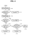
- FIG. 4 is a flow chart which determines an operation pattern by applying a probability model for excavation operation of the construction machinery, according to an exemplary embodiment of the present invention.
- FIG. 5 is a flow chart which determines an operation pattern by applying a probability model for ground leveling operation of the construction machinery, according to an exemplary embodiment of the present invention.
- FIG. 6 is a flow chart which determines an operation pattern by applying a probability model for lifting operation of the construction machinery, according to an exemplary embodiment of the present invention.
- FIG. 1 illustrates a configuration of an apparatus for controlling construction machinery, according to an exemplary embodiment of the present invention.
- the aforementioned construction machinery includes various types of equipment, but an excavator will be described as an example in the present exemplary embodiment.
- the apparatus for controlling construction machinery analyzes operation that is being currently performed by the excavator and controls each operation apparatus to match an operation pattern.
- the apparatus for controlling construction machinery includes an operation pattern recognition apparatus 110, a driving control apparatus 126, and a screen display unit 124.
- the operation pattern control apparatus may be used in the construction machinery such as a forklift or a crane as well as the excavator to control individual equipment in accordance with the operation pattern.
- the operation pattern recognition apparatus includes a data accumulation unit 112 which receives a manipulation signal of each operation apparatus from a joystick 100 and accumulates the manipulation signal, an operation pattern analysis unit 114 which analyzes data of the accumulated manipulation signal and determines the present operation pattern, a probability model analysis unit 122 which determines data of which an operation pattern is not determined by the operation pattern analysis unit 114 by using a probability model, and a pattern result output unit 120 which outputs operation determined by the operation pattern analysis unit 114 and the probability model analysis unit 122 to the driving control apparatus 126 and the screen display unit 124.
- the present exemplary embodiment has described as an example that the data accumulation unit 112 accumulates the manipulation signal, but the present invention is not limited thereto.
- the data accumulation unit 112 may be used in an aspect in which a signal outputted from the driving control apparatus 126 to each operation apparatus or a signal outputted from a sensor that measures an acutal drive amount of each operation apparatus is accumulated in the data accumulation unit 112.
- the operation pattern analysis unit 114 includes a first operation group pattern analysis unit 116 which determines the accumulated manipulation signal as a first operation group, and a second operation group pattern analysis unit 118 which determines the accumulated manipulation signal as a second operation group.
- the first operation group may include first operation, and the first operation may be lifting operation for conveying soil and sand.
- the second operation group may include second and third operation, the second operation may be excavation operation for digging into the ground, and the third operation may be ground leveling operation for land grading.
- the first to third operation are not limited to the lifting operation, the excavation operation, and the ground leveling operation, but will be described as examples.
- the first operation group pattern analysis unit 116 analyzes data of the accumulated manipulation signal and determines the result as the first operation (lifting operation).
- the first operation group pattern analysis unit 116 outputs the data, which is determined as the first operation (lifting operation), to the pattern result output unit 120, and outputs the data, which is not determined as the first operation (lifting operation), to the second operation group pattern analysis unit 118.
- the second operation group pattern analysis unit 118 analyzes the data outputted from the first operation group pattern analysis unit 116 and determines the result as the second operation (excavation operation) or the third operation (ground leveling operation).
- the second operation group pattern analysis unit 118 outputs the data, which is determined as the second operation (excavation operation) or the third operation (ground leveling operation), to the pattern result output unit 120, and outputs the data, which is not determined as the second operation (excavation operation) or the third operation (ground leveling operation), to the probability model analysis unit 122.
- the probability model analysis unit 122 determines the data, which is not analyzed by the operation pattern analysis unit 114, as first to fourth operation (lifting operation, excavation operation, ground leveling operation, and trenching operation) by using a probability model, and then outputs the result to the pattern result output unit 120.
- the fourth operation may be trenching operation which is difficult to be distinguished as one of the second operation and the third operation because the second operation (excavation operation) and the third operation (ground leveling operation) are combined.
- the probability model analysis unit 122 determines an operation pattern of the data by applying the probability model according to the third operation (ground leveling operation).
- the probability model according to each operation may be illustrated as Table 1.
- A means the excavation operation (second operation)
- B means the ground leveling operation (third operation)
- C means the lifting operation (first operation)
- D means the trenching operation (fourth operation)
- a ⁇ 0.8 means that the frequency of the an operation is equal to or more than 80% of the whole data
- B all means that the whole data is the B operation
- B! all means that the whole data is not the B operation
- N.D Not Distinguishable
- the pattern result output unit 120 transmits the first to fourth operation (lifting operation, excavation operation, ground leveling operation, and trenching operation) determined from the operation pattern analysis unit 114 and the probability model analysis unit 122 to the screen display unit 124 and the driving control apparatus 126.
- the driving control apparatus 126 controls the individual equipment, and includes an engine driving control unit 130, a pump driving control unit 132, and a valve driving control unit 134.
- the driving control apparatus 126 controls the individual equipment according to the operation pattern result received from the pattern result output unit 120.
- FIG. 2 is a flow chart illustrating an operation pattern control method according to the present invention.
- the data accumulation unit 112 receives the manipulation signal of the individual equipment from the joystick 100, and accumulates the manipulation signal (S20 and S22). At this time, the first operation group pattern analysis unit 116 determines whether or not the accumulated signal is present in the data accumulation unit 112 (S24).
- the first operation group pattern analysis unit 116 outputs a stop signal to the screen display unit 124 and the driving control apparatus 126 (S42).
- the first operation group pattern analysis unit 116 analyzes whether or not the whole data is a travel signal or whether or not there is another signal other than the travel signal (S26).
- the first operation group pattern analysis unit 116 determines whether or not the immediately previous operation was the first operation (lifting operation) (S44). When the immediately previous operation is the first operation (lifting operation), the first operation group pattern analysis unit 116 determines the data as the first operation group. In the present exemplary embodiment, because only the case in which the "lifting operation" is included in the first operation group is set and described, the first operation group pattern analysis unit 116 determines the present operation as the "lifting operation" and outputs the result to the screen display unit 124 and the driving control apparatus 126.
- the first operation group pattern analysis unit 116 determines whether or not the data is the first operation (lifting operation) (S28).
- the first operation group pattern analysis unit 116 determines the present operation as the "lifting operation” and outputs the result to the screen display unit 124 and the driving control apparatus 126 (S48).
- the "first operation (lifting operation)” is displayed on the screen display unit 124 (S36), and the driving control apparatus 126 controls the individual equipment to match the lifting operation pattern (S38).
- the first operation group pattern analysis unit 116 outputs the data to the second operation group pattern analysis unit 118. Because most of the operation of the excavator starts by operation of an arm, and therefore operation patterns may be differentiated according to a drive pattern of the arm, the second operation group pattern analysis unit 118 analyzes the data for each period based on a signal of the arm (S30).
- the second operation group pattern analysis unit 118 determines whether or not the data is the second operation group (S32). It is preferred that the second operation group includes operation that is not included in the first operation group. In the present exemplary embodiment, only the case in which the second operation group includes the second operation (excavation operation) and the third operation (ground leveling operation) will be described.
- the second operation group pattern analysis unit 118 determines the present operation as the "excavation operation” or the "ground leveling operation”, and outputs the result to the screen display unit 124 and the driving control apparatus 126 (S50). Accordingly, the "excavation operation” or the “ground leveling operation” is displayed on the screen display unit 124 (S36), and the driving control apparatus 126 controls the individual equipment to match the operation pattern of the excavation operation or the ground leveling operation (S38).
- the second operation group pattern analysis unit 118 outputs the data, which is not determined, to the probability model analysis unit 122.
- the probability model analysis unit 122 determines the data, which is not analyzed by the operation pattern analysis unit 114, as the first to fourth operation (lifting operation, excavation operation, ground leveling operation, and trenching operation) by using the probability model, and supplies the determined data to the screen display unit 124 and the driving control apparatus 126. Accordingly, the data is displayed on the screen display unit 124 in accordance with the first to fourth operation patterns determined through the probability model analysis unit 122 (S36), and the driving control apparatus 126 controls the individual equipment in accordance with the first to fourth operation patterns (S38).
- the fourth operation may be trenching operation which is difficult to be distinguished as one of the second operation and the third operation because the second operation (excavation operation) and the third operation (ground leveling operation) are combined.
- the present invention controls the individual equipment in accordance with each operation pattern, and as a result, fuel efficiency may be improved, and unnecessary fuel consumption may be reduced.
- FIG. 3 is a flow chart according to the probability model analysis unit illustrated in FIG. 1 .
- the probability model analysis unit 122 analyzes frequency of operation with respect to the data that is not determined from the operation pattern analysis unit 114 (S50).
- the probability model analysis unit 122 determines the operation having high frequency among the data, and determines the data as the first to fourth operation (lifting operation, excavation operation, ground leveling operation, and trenching operation) in accordance with the operation having maximum frequency by applying the probability model according to each operation, and outputs the result.
- the probability model analysis unit 122 determines whether or not the operation having a mode value is the second operation (excavation operation) (S60). In a case in which the operation having a mode value is the second operation (excavation operation), the probability model analysis unit 122 determines the data by applying the probability model according to the second operation (excavation operation) (S62).
- the probability model analysis unit 122 determines whether or not the operation having a mode value is the third operation (ground leveling operation) (S70). In a case in which the operation having a mode value is the third operation (ground leveling operation), the probability model analysis unit 122 determines the data by applying the probability model according to the third operation (ground leveling operation) (S72).
- the probability model analysis unit 122 determines whether or not the operation having a mode value is the first operation (lifting operation) (S 80). In a case in which the operation having a mode value is the first operation (lifting operation), the probability model analysis unit 122 determines the data by applying the probability model according to the first operation (lifting operation) (S82).
- FIG. 4 is a flow chart which determines an operation pattern by applying data to excavation probability model when excavation operation has a mode value.
- the first reference value means the frequency of operation equal to or more than 80% (S 160 and S 162)
- the probability model analysis unit 122 determines the present operation as the "excavation operation", and outputs the result to the screen display unit 124 and the driving control apparatus 126 (S 172). Accordingly, the outputted operation is displayed on the screen display unit 124, and the driving control apparatus 126 controls the individual equipment in accordance with the excavation operation pattern.
- the probability model analysis unit 122 analyzes the frequency of the lifting operation (S 164). That is, whether or not the frequency of the lifting operation is equal to or more than a second reference value is determined (S166).
- the second reference value means the number of times of the lifting operation that is equal to or more than two.
- the probability model analysis unit 122 determines the present operation as "impossible to determine", and outputs the result to the screen display unit 124 and the driving control apparatus 126 (S 174).
- the probability model analysis unit 122 determines whether or not the frequency of the lifting operation is a third reference value (S 168).
- the third reference value means the number of times of the lifting operation that is one.
- the probability model analysis unit 122 determines the present operation as the fourth operation, that is, the "trenching operation”, and outputs the result to the screen display unit 124 and the driving control apparatus 126 (S 170). Accordingly, the "trenching operation” is displayed on the screen display unit 124, and the driving control apparatus 126 controls the individual equipment in accordance with the "trenching operation".
- the fourth reference value means the frequency of operation that is equal to or more than 85%.
- the probability model analysis unit determines the present operation as the "excavation operation”, and outputs the result (S 180).
- the probability model analysis unit determines the present operation as the "trenching operation", and outputs the result (S178).
- FIG. 5 is a flow chart which determines an operation pattern by applying data to a ground leveling probability model, when the ground leveling operation has a mode value.
- the fifth reference value means the frequency of operation of 100%.
- the probability model analysis unit 122 determines the present operation as the "ground leveling operation", and outputs the result to the screen display unit 124 and the driving control apparatus 126. Accordingly, the "ground leveling operation” is displayed on the screen display unit 124, and the driving control apparatus 126 controls the individual equipment in accordance in accordance with a ground leveling operation pattern (S 196).
- the probability model analysis unit 122 determines whether or not the immediately previous operation is the trenching operation (S 184).
- the probability model analysis unit 122 determines whether or not the frequency of the lifting operation is equal to or more than a sixth reference value (S198 and S200).
- the sixth reference value means the number of times of the lifting operation that is equal to or more than two.
- the probability model analysis unit 122 determines the present operation as "impossible to determine", and outputs the result to the screen display unit 124 and the driving control apparatus 126 (S206).
- the probability model analysis unit 122 determines whether or not the frequency of the lifting operation is a seventh reference value (S202).
- the seventh reference value means the number of times of the lifting operation that is one.
- the probability model analysis unit 122 determines the present operation as the "trenching operation”, and outputs the result to the screen display unit 124 and the driving control apparatus 126 (S208). Accordingly, the "trenching operation” is displayed on the screen display unit 124, and the driving control apparatus 126 controls the individual equipment in accordance with the "trenching operation".
- the probability model analysis unit 122 determines whether or not all the data except for the lifting operation are the ground leveling operation (S204). In a case in which all the data except for the lifting operation are the ground leveling operation, the probability model analysis unit 122 determines the data as the "ground leveling operation” and outputs the result (S212). In a case in which no data except for the lifting operation are the ground leveling operation, the probability model analysis unit 122 determines the data as the "trenching operation" and outputs the result (S210).
- the probability model analysis unit 122 determines whether or not the frequency of the lifting operation is equal to or more than an eighth reference value (S186 and S188).
- the eighth reference value means the number of times of the lifting operation that is equal to or more than two.
- the probability model analysis unit 122 determines the present operation as "impossible to determine", and outputs the result to the screen display unit 124 and the driving control apparatus 126 (S214).
- the probability model analysis unit 122 determines whether or not the frequency of the lifting operation is a ninth reference value (S 190).
- the ninth reference value means the number of times of the lifting operation that is one.
- the probability model analysis unit 122 determines whether or not a ratio of the ground leveling operation is equal to or more than a tenth reference value.
- the tenth reference value is 85% (S192).
- the probability model analysis unit 122 determines the present operation as the "ground leveling operation”, and outputs the result (S222).
- the probability model analysis unit 122 determines the present operation as the "trenching operation", and outputs the result S 194).
- the probability model analysis unit 122 determines whether or not all the data except for the lifting operation are the ground leveling operation (S216). In a case in which all the data except for the lifting operation are the ground leveling operation, the probability model analysis unit 122 determines the present operation as the "ground leveling operation", and outputs the result S218). In a case in which no data except for the lifting operation are the ground leveling operation, the probability model analysis unit 122 determines the present operation as the "trenching operation", and outputs the result (S220).
- FIG. 6 is a flow chart which determines an operation pattern by applying data to a lifting probability model in a case in which lifting operation has a mode value.
- the eleventh reference value means the number of times of the lifting operation that is equal to or more than six.
- the probability model analysis unit 122 determines the present operation as the "lifting operation”, and outputs the result to the screen display unit 124 and the driving control apparatus 126 (S234). Accordingly, the outputted operation is displayed on the screen display unit 124, and the driving control apparatus 126 controls the individual equipment in accordance with a lifting operation pattern.
- the probability model analysis unit 122 determines the present operation as "impossible to determine", and outputs the result to the screen display unit 124 and the driving control apparatus 126 (S236).
- the method of controlling construction machinery may improve fuel efficiency by controlling each operation apparatus of the construction machinery such as an excavator in accordance with operation patterns.
Landscapes
- Engineering & Computer Science (AREA)
- Mining & Mineral Resources (AREA)
- Civil Engineering (AREA)
- General Engineering & Computer Science (AREA)
- Structural Engineering (AREA)
- Mechanical Engineering (AREA)
- Physics & Mathematics (AREA)
- General Physics & Mathematics (AREA)
- Automation & Control Theory (AREA)
- Operation Control Of Excavators (AREA)
- Component Parts Of Construction Machinery (AREA)
Applications Claiming Priority (2)
| Application Number | Priority Date | Filing Date | Title |
|---|---|---|---|
| KR1020100081222A KR101799101B1 (ko) | 2010-08-23 | 2010-08-23 | 건설기계의 작업 패턴 인식 장치 및 작업 패턴 인식 방법 |
| PCT/KR2011/006203 WO2012026732A2 (ko) | 2010-08-23 | 2011-08-23 | 건설기계의 제어 장치 및 제어방법 |
Publications (1)
| Publication Number | Publication Date |
|---|---|
| EP2610407A2 true EP2610407A2 (de) | 2013-07-03 |
Family
ID=45723916
Family Applications (1)
| Application Number | Title | Priority Date | Filing Date |
|---|---|---|---|
| EP11820159.9A Withdrawn EP2610407A2 (de) | 2010-08-23 | 2011-08-23 | Vorrichtung und verfahren zur steuerung einer baumaschine |
Country Status (5)
| Country | Link |
|---|---|
| US (1) | US20130158679A1 (de) |
| EP (1) | EP2610407A2 (de) |
| KR (1) | KR101799101B1 (de) |
| CN (1) | CN103069083B (de) |
| WO (1) | WO2012026732A2 (de) |
Families Citing this family (4)
| Publication number | Priority date | Publication date | Assignee | Title |
|---|---|---|---|---|
| CN103857844B (zh) * | 2011-10-05 | 2016-11-23 | 沃尔沃建造设备有限公司 | 用于控制使用挖掘机的土地平整工作的系统 |
| KR102425743B1 (ko) * | 2015-08-21 | 2022-07-28 | 현대두산인프라코어(주) | 건설기계 및 건설기계의 제어 방법 |
| JP7328212B2 (ja) * | 2018-03-30 | 2023-08-16 | 住友重機械工業株式会社 | 建設機械の運転支援システム、建設機械 |
| US11697917B2 (en) * | 2019-07-26 | 2023-07-11 | Deere & Company | Anticipatory modification of machine settings based on predicted operational state transition |
Family Cites Families (9)
| Publication number | Priority date | Publication date | Assignee | Title |
|---|---|---|---|---|
| JPH0526089Y2 (de) * | 1987-07-10 | 1993-07-01 | ||
| KR940000039B1 (ko) * | 1987-08-19 | 1994-01-05 | 가부시기가이샤 히다찌세이사꾸쇼 | 전자식 엔진 제어장치 |
| US5065326A (en) * | 1989-08-17 | 1991-11-12 | Caterpillar, Inc. | Automatic excavation control system and method |
| CA2125375C (en) * | 1994-06-07 | 1999-04-20 | Andrew Dasys | Tactile control for automated bucket loading |
| US5999872A (en) * | 1996-02-15 | 1999-12-07 | Kabushiki Kaisha Kobe Seiko Sho | Control apparatus for hydraulic excavator |
| KR20030025473A (ko) * | 2001-09-21 | 2003-03-29 | 현대중공업 주식회사 | 굴삭기의 작업량 산출을 위한 작업 모드 구분 방법 |
| WO2004029435A1 (ja) * | 2002-09-26 | 2004-04-08 | Hitachi Construction Machinery Co., Ltd. | 建設機械の原動機制御装置 |
| JP5275658B2 (ja) * | 2008-03-27 | 2013-08-28 | 株式会社小松製作所 | 作業車両の作業量推定システム及び作業車両 |
| KR101428099B1 (ko) * | 2008-11-19 | 2014-08-08 | 두산인프라코어 주식회사 | 건설기계의 유압회로 |
-
2010
- 2010-08-23 KR KR1020100081222A patent/KR101799101B1/ko not_active Expired - Fee Related
-
2011
- 2011-08-23 WO PCT/KR2011/006203 patent/WO2012026732A2/ko not_active Ceased
- 2011-08-23 CN CN201180041004.9A patent/CN103069083B/zh not_active Expired - Fee Related
- 2011-08-23 EP EP11820159.9A patent/EP2610407A2/de not_active Withdrawn
- 2011-08-23 US US13/818,621 patent/US20130158679A1/en not_active Abandoned
Non-Patent Citations (1)
| Title |
|---|
| See references of WO2012026732A3 * |
Also Published As
| Publication number | Publication date |
|---|---|
| US20130158679A1 (en) | 2013-06-20 |
| CN103069083A (zh) | 2013-04-24 |
| CN103069083B (zh) | 2016-11-02 |
| KR101799101B1 (ko) | 2017-11-20 |
| KR20120021920A (ko) | 2012-03-09 |
| WO2012026732A2 (ko) | 2012-03-01 |
| WO2012026732A3 (ko) | 2012-05-18 |
Similar Documents
| Publication | Publication Date | Title |
|---|---|---|
| DE112011100307B4 (de) | Maschinensteuerungs- und Leitsystem mit einer tragbaren digitalen Datenträgervorrichtung | |
| EP2610407A2 (de) | Vorrichtung und verfahren zur steuerung einer baumaschine | |
| DE102020110306A1 (de) | System und Verfahren zur Aufrechterhaltung einer Arbeitsfläche auf einer Baustelle | |
| US20080162004A1 (en) | Machine control system and method | |
| US20130230212A1 (en) | Automated track surveying and ditching | |
| CN104847262A (zh) | 一种可移动式专业土壤修复综合钻机及环境修复的方法 | |
| KR102045263B1 (ko) | 굴삭기 고장 예측 장치 및 이의 동작 방법 | |
| CN105992850A (zh) | 作业车辆的控制系统、控制方法以及作业车辆 | |
| CN108049393A (zh) | 用于富水厚砂层条件下的地铁车站附属围护结构施工工艺 | |
| CN107091097A (zh) | 一种矩形顶管机 | |
| KR101626657B1 (ko) | 굴삭기 버켓의 위치 제어 시스템 | |
| US20160349733A1 (en) | Machine Performance Evaluation and Feedback System | |
| WO2023027855A1 (en) | Loading machine with visual reference system | |
| CN114411843A (zh) | 正铲式挖掘机提升及推压机构的零位标定装置和方法 | |
| CN112962691A (zh) | 一种基于北斗定位的挤密桩质量管控信息化系统 | |
| CN112211551A (zh) | 一种带有实时垂直度检测的旋挖机及其实现方法 | |
| CN112031052A (zh) | 推土机施工管控系统及方法 | |
| KR102363728B1 (ko) | 건설현장의 미세먼지 배출량 예측 방법 및 장치 | |
| WO2022215414A1 (ja) | 掘削システム | |
| CN102561415A (zh) | 挖掘机 | |
| CN223991396U (zh) | 一种基于可调式定型挖斗的排水沟高效开挖装置 | |
| JPH03295934A (ja) | 切盛土工事における法面整形施工法及び施工装置 | |
| KR20170046356A (ko) | 건설기계의 유압 제어 시스템 | |
| EP4253669B1 (de) | Vermessungssystem für eine bau- und arbeitsmaschine | |
| CN112431188A (zh) | 一种湿陷性黄土地质非适宜材料复合地基施工工法 |
Legal Events
| Date | Code | Title | Description |
|---|---|---|---|
| PUAI | Public reference made under article 153(3) epc to a published international application that has entered the european phase |
Free format text: ORIGINAL CODE: 0009012 |
|
| 17P | Request for examination filed |
Effective date: 20130314 |
|
| AK | Designated contracting states |
Kind code of ref document: A2 Designated state(s): AL AT BE BG CH CY CZ DE DK EE ES FI FR GB GR HR HU IE IS IT LI LT LU LV MC MK MT NL NO PL PT RO RS SE SI SK SM TR |
|
| RIN1 | Information on inventor provided before grant (corrected) |
Inventor name: JANG, DAL SIK Inventor name: KIM, KI YOUNG Inventor name: OH, JOONHO Inventor name: HONG, DAEHIE |
|
| RIN1 | Information on inventor provided before grant (corrected) |
Inventor name: JANG, DAL SIK Inventor name: OH, JOONHO Inventor name: KIM, KI YOUNG Inventor name: HONG, DAEHIE |
|
| DAX | Request for extension of the european patent (deleted) | ||
| STAA | Information on the status of an ep patent application or granted ep patent |
Free format text: STATUS: THE APPLICATION HAS BEEN WITHDRAWN |
|
| 18W | Application withdrawn |
Effective date: 20160706 |