-
The invention relates to a laundry dryer having a steam generation unit and a nozzle unit for supplying steam into a laundry treatment compartment for steam treatment.
-
US 4,207,683 A suggests a laundry dryer with a laundry storing compartment defined by a cylindrical rotatable drum, a loading opening at the front end of the drum and a stationary back wall at the rear end. For removing of wrinkles from or static electricity on the laundry, water is applied to the laundry from a water container or steam is supplied from a steam generator in form of a heated boiler. The steam from the boiler is injected into the laundry storing compartment through a nozzle that is arranged at the upper end of the stationary back wall.
-
It is an object of the invention, to provide a laundry dryer in which the steam treatment of laundry is further improved.
-
The invention is defined in claim 1. Particular embodiments of the invention are set out in the dependent claims.
-
According to claim 1 a laundry dryer is provided which has a laundry storing compartment that is defined by a - preferably horizontally supported - rotatable drum that has an open front side and preferably an open back side. The open front side of the drum is used to load laundry into the laundry storing compartment through a loading opening formed in the front wall of the dryer. The dryer comprises a steam generation unit for generating steam which is supplied into the laundry storing compartment for laundry steam treatment. The steam is flowing from a nozzle unit into the laundry storing compartment, wherein the nozzle unit has at least one or a plurality of outlets for injecting the steam into the laundry storing compartment. The nozzle unit is arranged at the back wall of the laundry storing compartment opposite to the loading opening, wherein the back wall may be a rotating back wall connected to and rotating with the drum. Preferably the back wall is a stationary back wall.
-
The steam generating unit may be any steam generating unit, like a boiler-type steam generator or preferably a flow-through steam generator that transforms the supplied liquid into steam with a rate corresponding to the liquid supply rate. The steam generator is preferably arranged in the cabinet of the dryer, more preferably is arranged at a lower region of the dryer, e.g. below the laundry storing compartment and/or at a basement cover shell - for example of a heat pump system dryer.
-
The dryer may be any type of dryer, like an exhaust type dryer that exhausts the drying air to the outside of the dryer body after the process air has passed the laundry storing compartment. Preferably the dryer is a condenser type in which the processing air is (substantially or the most time) circulated in a closed loop and the humidity from the laundry is condensed at a process air heat exchanger or condenser and collected in at least one condensate collection tank. The condenser type dryer may use ambient or outside air for heat exchanging or may use a heat pump system.
-
In the invention the nozzle unit comprises a nozzle body which is projecting from the back wall of the laundry storing compartment so as to extend into the laundry storing compartment. By the protrusion of the nozzle into the laundry storing compartment, the steam can be supplied at a location that is placed 'deeper' in the laundry treatment volume of the storing compartment so that the steam is more intensely and evenly distributed among the laundry. Thus it is e.g. prevented that laundry which adheres to a compartment wall may cover one or more nozzles of the nozzle body and prevents steam release into the compartment.
-
Further the nozzle unit provides a steam/liquid separator function in that the nozzle body comprises a hollow internal volume, a steam inlet fluidly connected to the steam generation unit and at least one steam outlet (nozzle) fluidly connected to the laundry storing compartment. Due to the hollow internal volume, the speed of the steam is reduced and liquid transported with the steam through steam supply line or condensate formed in the supply line can be separated from the steam. In particular when the hollow internal volume is or is essentially arranged in the storing compartment (i.e. in the protruding nozzle body) and/or is extending directly to the steam nozzle outlet(s) of the nozzle body, the liquid is effectively prevented from entering the storing compartment and contacting the laundry therein. Preferably the nozzle unit provides a or this steam/liquid separator arrangement in a way such that the steam/liquid separator is located or is completely located within the laundry treatment compartment.
-
In an embodiment the drum has a cylindrical or essentially cylindrical body rotatably mounted in the dryer, wherein the back wall is stationary and the open rear end of the drum is rotatably coupled to the stationary back wall. Preferably a sealing arrangement is provided between the rear end of the drum and the back wall or a rear frame.
-
Preferably the nozzle body has one or a plurality of nozzle outlets, wherein the majority of the nozzle outlets or all of the (plurality) of nozzle outlets are (essentially) arranged at the upper half of the nozzle body. The 'facing upward' of the nozzles at the nozzle body directs the steam into a volume region of the storing compartment where the steam can distribute without less obstacles (laundry) and at the same time light weight steam escapes from the nozzle body while heavy droplets are withhold in the nozzle body to prevent direct contact between hot liquid and laundry.
-
In an embodiment the projection of the nozzle body provides a detangling function for the laundry or reduces tangling of the laundry during any treatment process in which the drum is rotated. Such processes are for example a drying process and the steam treatment process in which the drum is rotated at least temporally. The projecting nozzle body deflects the laundry during tumbling and thus redistributes the laundry to avoid clustering and to provide a slackening.
-
In an embodiment the liquid separated and collected in the nozzle body is held therein until being transformed back to steam and removed from the nozzle body via the steam outlet(s) or nozzle(s). Evaporation heat may be provided by the heat of the supplied steam or during a process air circulation period, for example during a drying process. More preferably the nozzle body comprises a liquid or water outlet to drain condensate liquid or water formed in the hollow internal volume of the nozzle body out of the hollow internal volume. This avoids an overflow of collected liquid from the nozzle body into the storing compartment. Draining the liquid also removes a cooling source for fresh steam flowing through the nozzle body.
-
Draining of the liquid is improved when the nozzle body comprises a hollow internal volume and a water collector adapted to collect condensate liquid or water formed in the hollow internal volume or present in the steam flow. The water collector further has the function to guide the condensate liquid or water to a liquid outlet of the nozzle body. Thus the liquid is continuously removed out of the nozzle body with its formation and an overflow or dripping of liquid out of the nozzle body into the laundry storing compartment is prevented. Preferably the liquid outlet for draining the liquid from the nozzle body is arranged at a lowest point of the water collector. Preferably the liquid outlet of the nozzle body is in fluid connection with a condensate liquid collection container or a water tank where the liquid is collected to be removed manually or drained to an external drain. Alternatively or additionally the condensed liquid is re-used in that it is supplied to the steam generation unit. This can be done either in that the condensed liquid drained from the nozzle body is supplied directly to the steam generator. Or it can first be collected in a condensate container or tank from where it is re-fed to the steam generator. Examples of a condensate container for intermediate collection is the tank in the bottom of the dryer that e.g. also collects condensate from the drying process and/or a condensate drawer that collects condensate for manual deposit by the user.
-
In an embodiment a or the hollow internal volume of the nozzle body is arranged in a head region of the nozzle body, which is disposed with a distance or with an axial distance from the back wall of the laundry storing compartment surrounding the nozzle body. This 'spacing' of the hollow internal volume and of the steam outlet nozzles from the basis of the nozzle body at the back wall further improves steam injection into deeper regions of the storing compartment volume. This steam distribution is further assisted when one or more process air inlets of the back wall are arranged close to or preferably at least partially surrounding the nozzle body.
-
Preferably a process air channel is arranged at the backside of the back wall of the laundry storing compartment. Preferably further a condensate drainage conduit adapted to drain condensed liquid out of the nozzle body and/or a steam supply conduit adapted to supply steam from the steam generation unit to the nozzle body are passing from the nozzle body through the process air channel to the outside of the process air channel. Alternatively the conduit connector can be arranged in the process air channel such that the following correspondingly applies for a conduit connector arranged in the process air channel. In this way the supply to /draining from the nozzle body is provided such that process air can be supplied to the storing compartment with essentially no restriction by providing the nozzle unit and its infrastructure at the back wall. In particular when the process air inlet to the storing compartment is arranged close to or around the nozzle body, the process air can be supplied through the hollow channel structure behind the nozzle body.
-
Connecting the nozzle unit can be conveniently provided in that the nozzle unit further comprises a conduit connector which is arranged at the backside of the back wall and/or at the outside of the process air channel arranged at the backside of the back wall. The conduit connector is preferably in fluid connection with the nozzle body or the hollow internal volume of the nozzle body and/or is adapted to provide one or two connection sites for connecting one or two conduits for supplying steam to the nozzle body or the hollow internal volume of the nozzle body or to drain condensate liquid from the nozzle body or the hollow internal volume of the nozzle body, respectively. Preferably the conduit connector and the nozzle body provide a plug connection with one or two fluid connection conduits between the hollow internal volume of the nozzle body and the one or two connection sites. Additionally or alternatively the nozzle body or the conduit connector has one or two sockets for receiving the one or the two fluid connection conduits in a sealing manner. Preferably the one or two conduits are arranged at the nozzle rear wall or are integrally formed with the nozzle rear wall or the nozzle rear wall has one or two plug sockets for receiving the one or two conduits in a sealing manner, respectively.
-
In an embodiment the nozzle body is hollow and comprises a or the nozzle rear wall which defines the hollow internal volume in the nozzle body and which comprises a steam inlet to the hollow internal volume or a steam inlet to and a condensate outlet from the hollow internal volume, wherein the nozzle body and the nozzle rear wall are formed of two separate parts that are fitted or fixed together. Alternatively or additionally the steam inlet fluidly connects the hollow internal volume to the steam generating unit and/or the liquid outlet is adapted to drain liquid or water from the hollow internal volume. In a preferred configuration, the steam inlet is arranged above the liquid outlet or the steam inlet is arranged at the same or essentially the same horizontal level. Thus it is prevented that liquid or liquid droplets pass the way of the steam supplied to the hollow internal volume which would cool down or condensate the steam.
-
Preferably the outer shape of the nozzle body, which is protruding into the laundry storing compartment, has the form or has essentially the form of a dome or cone. This form improves the detangling function of the nozzle body. Alternatively or additionally the nozzle unit is arranged in the center or at a central region of the back wall - which also improves the detangling function and which also improves distribution of steam to the storing compartment volume, in particular when the nozzle body is at least partially surrounded by process air inlets a the back wall.
-
In an embodiment the nozzle unit comprises a mounting base which is adapted to be mounted on the back wall of the laundry storing compartment and which is adapted for mounting the nozzle body thereon. Preferably the mounting base or the nozzle body comprises at least one spacer that is protruding from the rear side of the mounting base or nozzle body. Preferably the at least one spacer is adapted to run across the or a process air channel arranged at the backside of the back wall to provide a predefined minimum gap across the process air channel in the direction of the one or more spacers. This prevents a compression of the process air channel by the tumbling laundry in the drum and provides more stability against pressing forces applied from the backside of the dryer.
-
The dryer may further comprise a back frame extending from a base region to an upper region at the back region of the dryer. Preferably the back frame comprises one, two or more passages or openings adapted to guide one or both of a steam supply line to or a condensate back flow line from the nozzle unit through the back frame.
-
Reference is made in detail to a preferred embodiment of the invention, an example of which is illustrated in the accompanying figures, which show:
- Fig. 1
- a perspective view of a partially disassembled condenser dryer,
- Fig. 2
- the front view of the dryer of Fig. 1,
- Fig. 3
- a perspective view of a front wall, a front frame and portion of a front panel of the dryer of Fig. 1,
- Fig. 4
- the perspective view with the front wall and the front frame where the front panel and a lid are shown in exploded illustration,
- Fig. 5
- the front view with the condensate drawer taken out from the drawer compartment of the dryer,
- Fig. 6
- a cross section perpendicular to the front plane in an upper front area taken along the line A-A shown in Fig. 5 where the filter/valve unit of a reservoir is arranged,
- Fig. 7
- in top view from left to right the front frame, the reservoir, a filling unit of the reservoir and the front wall,
- Fig. 8
- an exploded view of the front frame, the reservoir, the filling unit and the front wall,
- Fig. 9
- a perspective view of the front frame with mounted reservoir and filling unit, and a fluff filter partially lifted in the process air channel,
- Fig. 10
- the perspective view of Fig. 9 with the fluff filter completely inserted in the process air channel,
- Fig. 11
- a front view of the front frame with the reservoir and reservoir piping mounted,
- Fig. 12
- a perspective view of the front frame, a rear frame and a steam generator arranged between on a base section cover shell,
- Fig. 13
- a side view of the front frame, the steam generator and further reservoir piping,
- Fig. 14
- a rear view of the front frame showing conduit passages and an overflow pipe,
- Fig. 15a
- the reservoir in more detail in exploded view,
- Fig. 15b
- the reservoir in assembled state with the filling unit disassembled,
- Fig. 16a to 16c
- a front view, a left side view and a top view of the reservoir,
- Fig. 17a
- the sectional view of the reservoir along line A-A in Fig. 16a,
- Fig. 17b
- the sectional view of the reservoir along line B-B in Fig. 16a,
- Fig. 17c
- the sectional view of the reservoir along line C-C in Fig. 16a,
- Fig. 17d
- the sectional view of the reservoir along line D-D in Fig. 16a,
- Fig. 17e
- the sectional view of the reservoir along horizontal line E-E in Fig. 16a,
- Fig. 17f
- a detail of a level detector and PCB holder as detail A from Fig. 15a,
- Fig. 18a
- a detail view of the filling area in exploded view as detail A from Fig. 4,
- Fig. 18b and 18c
- the detail view of the filling area as enlarged detail A from Fig. 3 with a valve switch in valve open position (18b) and valve closed position (18c),
- Fig. 19a and 19b
- sectional views through the filling unit of the reservoir with a valve filter open (19a) and closed (19b),
- Fig. 20a and 20b
- a top view to the front frame and the front wall with (20a) and without (20b) a portion of the front panel where the drawer opening is arranged,
- Fig. 21
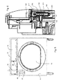
- a detail view of the laundry compartment back wall with a steam inlet cone as a detail A from Fig. 12,
- Fig. 22
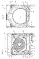
- the front frame, the rear frame and the basement top cover at the battery channel in cross section along section B-B in Fig. 11,
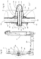
- Fig. 23
- a steam inlet unit with the steam inlet cone in cross section as detail C from Fig. 22 or cross section similar to the section A-A of Fig. 27,
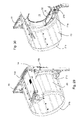
- Fig. 24
- the steam inlet unit in exploded view,
- Fig. 25
- a rear perspective view of the dryer with the bottom unit and right side wall removed,
- Fig. 26
- the rear view of the steam inlet unit mounted as detail B from Fig. 25,
- Fig. 27
- a front view of the steam inlet unit with the rear frame and back wall shell removed,
- Fig. 28
- a block diagram showing some of the components of the dryer and their functional or connection relation to each other,
- Fig. 29
- a rear perspective view to the drum, a condensate container housing and the front frame,
- Fig. 30
- the view of Fig. 29 with the condensate container and a portion of the drum wall removed,
- Fig. 31
- detail view B of Fig. 30 showing the front drum sealing, and
- Fig. 32
- another embodiment of the floater and the floater cage corresponding to Fig. 17d.
-
In the following a detailed embodiment of the invention is described using here as an exemplary home appliance or domestic appliance a dryer 2 of the condenser type.
-
Implementing the invention or portions of the invention in a condenser type dryer is preferred, however, the invention can also be implemented in any other type of dryer or in any other type of domestic appliance. For example the home appliance may be a washing machine having drying function with or without a heat exchanger or condensing unit.
-
Preferably the home appliance uses a heat exchanger in which condensate is collected and preferably supplied to the liquid reservoir (62 below). In the embodiments of the above examples of home appliances or in a further embodiment of a home appliance in which the invention may be implemented in a whole or in parts thereof is a laundry treatment machine in which steam is supplied to the laundry. The steam may be generated from water, fragrance, a deodorant, a sterilizer, liquid detergent, a waterproofing agent or any other agent, or any combination of these agents.
-
The following groups or sub-units of the domestic appliance can be implemented individually in the domestic appliance or in any combination of the groups:
- a front frame which has at least one passage or opening therein for guiding at least one liquid conduit therethrough;
- a front wall of the home appliance having an opening or window for inspection of a water level in a liquid reservoir arranged behind the opening or window, the reservoir preferably adapted to supply water to a steam generator;
- an upper front panel in which a panel window is provided to have access to servicing elements of a liquid reservoir (like a filling inlet for manually filling liquid, a filter and/or a valve); preferably the panel window is arranged at a frame for a drawer opening (opening to a drawer compartment, e.g. for condensate drawer); more preferably the drawer has a handling or grip portion that is arranged at a position adjacent to the panel window and/or the panel window is not part of a drawer housing or compartment in which a drawer is received;
- a steam supplying nozzle unit having a nozzle body extending into an interior of a preferably horizontally rotating laundry chamber, wherein the nozzle unit preferably provides a detangling function;
- a nozzle unit to supply steam into a laundry storing and treatment chamber having a nozzle body with a volume inside the laundry treatment chamber, wherein the nozzle volume provides a steam and droplet separation function in the interior of the laundry treatment chamber;
- a liquid reservoir storing treatment liquid adapted to treat laundry, wherein the reservoir is composed of at least two reservoir wall shells, wherein, when the wall shells are combined to provide the liquid storing container, a floater element is captured in a cage which is formed of at least a first cage part arranged at a first of the shells and of a second cage part which is formed at a second of the shells;
- a liquid reservoir for storing a treatment liquid adapted to treat laundry, wherein the liquid reservoir has a transparent element at an outer area thereof, adapted for visual inspection of a floater or the liquid level through the transparent element, and wherein the liquid reservoir further has a detector to detect the liquid level in the reservoir, preferably by using the floater;
- a condensate water filter element that is adapted to catch debris or fluff in a fluff trap to avoid insufficient sealing of a valve element; and/or
- a condensate water filter having a filter grid structure that reduces the filter flow resistance by providing an opening close to a filtered water outlet.
-
The following figures are not drawn to scale and are provided for illustrative purposes.
-
Fig. 1 shows a front perspective view of a partially disassembled condenser dryer that uses a heat pump system. In the shown state the loading door of the dryer 2, the right cover, the lower shell of a bottom unit and a bottom panel are removed. The outer appearance of the depicted dryer 2 is defined by a top cover 4, a left cover or wall 6, a front cover 8 having a loading opening 10 and a front top panel 12. The front top panel 12 frames a drawer cover 14, wherein here the drawer has a condensate container that is completely pushed in a drawer compartment located at the upper part of the dryer. The right portion of the front top panel 12 forms an input section 16 wherein here the details of the input section 16 are not shown (like indicators, a display, switches and so on).
-
The loading opening 10 is surrounded by a loading frame 18 which is formed in the front cover 8. In loading direction behind the bottom section of the loading frame 18 a filter compartment/process air channel 32 is arranged which is adapted to receive a fluff filter 34 and which is formed in a front frame 30 (compare Figs. 9 and 10). At the back side of the loading opening in the front frame 30 a drum 20 is arranged. In the embodiment shown the drum 20 is a rotating drum cylinder that is extending between the back side of the front frame 30 and the front side of a rear frame 31. The open rear end of cylindrical rotatable drum 20 is closed by a compartment back wall 26 (Fig. 2) which is mounted at the rear frame 31 (Fig. 12). Back wall 26 is preferably provided as a separate element to the rear frame 31, formed for example from a metal plate. In the shown embodiment the rotation axis of the drum is horizontal, however, the rotation axis may be inclined with respect to the horizontal axis or may be even vertical with some modifications to the shown embodiment, however without the requirement to modify other groups of the dryer.
-
Fig. 29 shows in perspective back view the drum 20, the front frame 30 and the drawer housing or compartment 15a in which the condensate drawer 15a is completely inserted. Below the condensate drawer compartment 15a and adjacent to the left upper corner of the front cover 8 or left above middle of the loading opening 10, a window panel 22 is inserted into a front cover window opening 52 (Fig. 4). The window opening 52 and the window panel 22 allow visual inspection into the inside of the dryer outer body where a liquid reservoir 62 is arranged to check the liquid level (see more detail below).
-
As indicated in Fig. 2 showing the dryer of Fig. 1 in front view, the condensate drawer has a draw handle 24 at the drawer cover 14 to be gripped by the user for pushing the condensate drawer in or pulling it out of the condensate drawer compartment that is extending into the interior of the dryer 2. Fig. 2 gives a view onto the compartment back wall 26 which has a plurality of air inlet openings 28 through which processing air enters the laundry storing compartment from the back side or rear side of the drum 20. In the center of the compartment back wall 26 and surrounded by the air inlet openings 28 a cone 252 is arranged which has in this embodiment laundry detangling function and further supplies steam into the interior of the laundry compartment formed by the drum 20, the back wall 26, the loading frames in the front frame 30 and the loading door (not shown). Fig. 3 shows a perspective front view of the front frame 30 with the front cover 8 mounted thereon. From the front top panel 12 only the drawer portion 13 with the drawer opening 36 is shown mounted at the upper section of the front frame 30. The condensate drawer and thus the drawer cover 14 are removed such that one can see details of the lower frame section of the drawer portion 13 which is surrounded by circle A. More details of view A can be seen in Figs. 18b and 18c and are described below. In the meantime it is mentioned that the lower frame section of the drawer opening 36 is exposed after extracting the condensate drawer, also exposing a user filling section 38. The user filling section 38 is covered by a lid 40 which is pivotably mounted at the lower frame of the drawer opening 36 of the drawer portion 13 via hinges 48 arranged at the lower drawer portion 13. The section 42 covered by lid 40 has a filter opening 44 in which a filter is inserted and has a filling opening 46 used to fill in water into the water reservoir 62 storing the water for steam generation. A typical value for the water storing volume in reservoir 62 is about 1.9 liters, preferably the volume is in a range of 1 to 3 liters, more preferably from 1 to 2, 2 to 3, 1.5 to 2.5 or 1.75 to 2.25 liters. Typically 0.7 liters are required for a steam treatment such that about 3 steam treatment cycles can be executed with the dryer 2 without manually replenishing liquid into the reservoir when no other liquid (e.g. condensate water) is supplied thereto.
-
It is to be noted that arranging the user filling section 38 in a lower frame portion of the drawer opening 36 allows a simple modification of standardized dryers for models that use steam generation and models that do not use steam generation. For models with steam generation the front top panel 12 with the user filling section 38 is used, while for models without steam generation there is no user filling section 38 and instead the lower portion of the frame of the drawer opening 36 is just a flat plate without any openings and/or lid.
-
Fig. 4 shows the arrangement of Fig. 3 partially exploded in that the front top panel 12 is lifted off from the front frame 30 and the lid 40 covering the section 42 of the user filling section 38 is also taken away. In Fig. 4 the user filling section 38 is a modified embodiment in which there is no separate division bar or rib which is dividing the filter opening 44 and the filling opening 46 as compared to the embodiment of Fig. 3. Instead there is a single opening which exposes the openings for filling in the water for steam generation and for exchanging or servicing the filter of the reservoir 62. In the exploded view one can see that there is an opening 50 in the top frame of the front cover 8. The opening 50 overlaps with the opening 44/46 when the front top panel 12 is mounted on the front frame 30, wherein the lower frame of the drawer opening 36 is arranged close to or abutting to and parallel to the front cover top frame. In another embodiment the front top panel 12, more specifically the drawer portion 13 forming the panel frame around drawer opening 36 just has a recess or gap over the filling inlet 136 and/or filter access 134 instead of the separate openings 44 and 46 in the drawer portion 13.
-
Further in Fig. 4 the window panel 22 is removed such that one can see the front cover window opening 52 which allows a view to the interior of the dryer just behind the front cover 8 where the reservoir 62 is arranged behind the window opening 52. The dryer models which use mainly the same components (for example the heat pump system, the base section, the front frame 30, the rear frame 31 and the drum) can be modified from between steam type by exchanging the front cover 8 having the opening 50 and 52 and the front cover having neither opening 50 nor 52. Also the front top panel 12 having the user filling section 38 or not can be exchanged between the models using the same standardized dryer (home appliance platform). In a modification the front cover 8 shown in Fig. 4 can be used always with the opening 50, while for example the opening 52 is closed by a closed or window-less panel (e.g. the window panel 22 without window) or the opening 52 may be provided by punching it, if the dryer model is provided with a steam generation unit and the reservoir 62. Fig. 18a shows the section A indicated in Fig. 4 in more detail.
-
Fig. 5 shows a front view of the front frame 30, the front cover 8 and the front top panel 12 without details of the input section 16 and with the condensate drawer removed such that the drawer opening 36 to the drawer compartment can be seen. Through the window panel 22 and the front cover window opening 52 a level window 68 of the reservoir 62 can be seen. The section A-A of Fig. 5 is shown in Fig. 6 which will be described in detail below.
-
Fig. 7 shows in top view from left to right the front frame 30, the reservoir 62, a reservoir inlet unit 70, the front cover 8 and the window panel 22. The reservoir 62 and the reservoir inlet unit 70 form together a reservoir unit 60 which has the function to store water to be supplied to a steam generator, to receive water filled in by a user manually and to filter condensate water which is pumped from a condensate collector of a condensate unit 92 to the reservoir 62. The reservoir 62 is forming a container composed of a front or first shell 64 and a rear or second shell 66 which are glued, welded, ultrasonic welded or otherwise mounted together. The level window 68 is protruding at the front side of the front shell 64 such that it is arranged immediately behind the front cover window opening 52 in the front cover 8 in the assembled state. At least the level window 68, preferably the complete front shell 64 or both shells 64 and 66 are made of a transparent material, like transparent PP, PE or acrylic glass.
-
The reservoir inlet unit 70 is a pluggable component that can be plugged into the reservoir 62 and provides the manual filling, condensate filling and filtering function to the reservoir 62. The reservoir inlet unit 70 has a condensate plug 132 that is protruding from the (back)surface of the unit 70 and is adapted to be inserted in a respective coupling or socket 106 (Fig. 15a) at the front side of the front shell 64. Condensate which was pumped from a condensate reservoir to the filter in the unit 70 exits the unit 70 towards the interior of reservoir 62 during a filling process for filling the reservoir with condensate water. A second plug is a filling plug 138 which protrudes at the back side of unit 70 and is adapted to be inserted in a respective coupling or socket 108 at the front shell 64. Liquid filled in manually into the unit 70 flows into the reservoir 62 via the filling plug 138.
-
It is to be mentioned that the individual elements or groups of elements of the reservoir inlet unit 70 may be integrated into the front and/or rear shell 64, 66 of the reservoir 62. The reservoir 62 and the reservoir inlet unit 70 are provided as two separate components in this embodiment for simplifying the manufacturing process of the front and rear shells 64, 66, as otherwise a more complex molding process would be required to integrate the functionality of unit 70 into the reservoir 62. However, the reservoir may be easily modified, for example in providing the shell separation in a horizontal plane instead of a vertical plane and the filter and filling openings may be arranged then in the upper shell for example.
-
Fig. 8 shows an exploded perspective view of the front frame 30, the reservoir 62, the filling unit 70, the front cover 8 and the panel 22. The front frame 30 has a reservoir mounting bracket 72 adapted to receive reservoir 62.
-
Fig. 9 shows the state in which the reservoir 62 is mounted at the front side of the front frame 30 and the unit 70 is mounted at the front side of reservoir 62. The reservoir and the unit 70 are dimensioned such that these make use of the hollow space or dead volume which is present in the dryer between the front side of front frame 30 and the back side of the front cover 8. This means that the structure of the front frame 30 is optimized for the supporting function of the frame in respect of mounting the components and cover elements of the dryer and the structure is further optimized and adapted such as to receive the reservoir unit 60 without compromising the required mechanical stability and by integrating the reservoir unit 60 under reduction of extra-space for it. In the embodiment - for further contributing to this optimization - the back side of reservoir 62 (here the rear shell 66) is adapted in a way to match the front structure of the front frame 30 and distribute the volume required for containing the liquid in the reservoir to areas and spaces between the frame 30 and the cover 8 where the respective space is available under preservation of the mechanical function of the front frame design elements and the front cover 8.
-
This means that the front frame 30 can be used in unmodified form as a platform element for a dryer model that has a reservoir unit (e.g. for the steam generation unit) as well as for a dryer model that does not make use of the reservoir unit (and the steam generation and steam treatment of the laundry). In the design optimizing process the front frame 30 is adapted to receive the reservoir unit (at least partially) such that no defective mechanical properties for the general purpose function of the front frame 30 are implemented, for example a riser feed through 74 is provided in a base area of the front frame without having an effect on its structural stability, while the feed through 74 provides an important liquid passage and/or pipe supporting function without requiring additional elements. This correspondingly applies for the overflow feed through 86 shown in Fig. 14.
-
Figs. 9 and 10 further show the arrangement of the fluff filter 34 in the process air channel section which is formed in the lower region of the front frame 30. The process air that has crossed the drum 20 is leaving the laundry treatment compartment at the lower section just in front of the loading frame 18 which is closed by a loading door through the channel section formed in frame 30 towards a battery channel 78 (Fig 11 shows upper part of battery channel as part of the upper basement shell or battery top cover 230) which provides another process air channel section formed in the base unit of the drum. The air in the process air channel section of the frame 30 is passing the fluff filter 34 to remove the fluff. Fluff filter 34 can be taken out of the process air channel section by pulling it upward as is indicated by the filter position shown in Fig. 9 as compared to the one in Fig. 10, where the filter is completely inserted for proper operation.
-
Fig. 11 shows a front view of the dryer with cover 8 and top cover 4 as well as left cover 6 removed and without a lower portion of the base section. On the bottom an upper portion or cover shell 230 of the base section 76 is shown which includes the upper portion 78 of the battery channel where the process air enters which comes through the process air channel section going through the front frame 30. The fluff filter 34 is also removed in this figure. As in Fig. 9 the reservoir unit 60 is mounted and the pipes connecting the unit to other elements are shown. A riser pipe 82 comes from the back side of the front frame 30 and is guided through the riser feed through 74 from where it goes upward to a filter inlet 98 (Fig. 15b) of the reservoir inlet unit 70. A feed pipe 84 is connected to a feed outlet 100 at the lower end of reservoir 62 and goes down at the front side of frame 30 and through a supply feed recess 75 formed at the lower edge of front frame 30. The riser pipe 82 and the feed pipe 84 are clamped by clamps 89 mounted at the front side of frame 30. The cross-sectional view indicated by section B-B in Fig. 11 is shown in Fig. 22 (similarly in Fig. 13).
-
Fig. 14 is a view to the back side of the front frame 30. An overflow pipe 88 is guided from an overflow feed through 86 in the upper region of the frame 30 to the lower region of the frame. The pipe 88 is mechanically fixed to the frame by clamps 89 provided at the backside of frame 30. The overflow feed through 86 is a passage from the front side to the rear side of frame 30 below the drawer opening 36 and is coinciding or overlapping with a overflow connection at the back side of the reservoir 62 (in front projection - compare overflow outlet 102 shown in Fig. 17c.)
-
The outlet of overflow pipe 88 is connected to a battery inlet 90 as can be seen from Figs. 12 and 13. Fig. 12 shows at 78 the upper shell of the battery channel. Overflow liquid that is descending in overflow pipe 88 enters the battery channel at 90 and is guided within the battery channel towards a condensate pump unit 92 where the condensate water that has condensed from the process air at the evaporator of the heat pump system is collected together with the liquid coming down the overflow pipe 88. The condensate pump unit 92 is assigned to the battery channel 78 and collects the condensate water and the overflow water from reservoir 62 in a condensate container (304 in Fig. 28). The pump (306 in Fig. 28) of the condensate pump unit 92 pumps the condensate from the condensate container to a liquid branch which has a first pump outlet 94, which is connected to the riser pipe 82, and a second pump outlet 96, which is connected to a pipe which supplies the condensate into the container (302 in Fig. 28) of the condensate drawer.
-
The respective flow resistances from the branch 94/96 through the pipes and vertical height difference to the reservoir inlet unit 70 and the condensate drawer (compare 15a in Fig. 29 or 302 in Fig. 28) are designed such that about 20% to 40% of the condensate water is supplied to reservoir 62 via unit 70 and the remainder of the condensate water is pumped to the condensate drawer (unless the filter valve 198 of the filter 190 in the reservoir inlet unit 70 is closed). Under normal operation conditions - as an average over several laundry treatment processes - the water consumed by steam generator 140 is less than the condensate water which is pumped from the condensate pump unit 92 into the reservoir 62. This guarantees that the reservoir 62 is always filled and normally needs not to be manually filled by the user. Further, as there is a higher condensate water amount pumped to the reservoir 62 than consumed by the steam generator 140, there is a steady or periodic overflow of condensate water which is flowing back through overflow pipe 88 from reservoir 62 into the battery channel 78 and from there back into the condensate pump unit 92. However, the circulation of this pumped and returned condensate water stops after a while as the higher proportion of the pumped condensate water finally collects in the condensate drawer until the condensate water level in the condensate pump unit 92 drops to a level where no condensate water will be pumped.
-
On the other hand, if the maximum level in the reservoir 62 and the maximum level in the condensate drawer 15a/302 are both reached or exceeded, the condensate pump unit 92 provides a signal initiated by a second maximum level in the condensate tank (304 in Fig. 28) to the control unit 300 which then stops operation of the dryer and/or stops a laundry drying process in which the condensate is formed by the laundry drying. The control unit 300 waits for the user draining the condensate drawer 15a/302 such that pump 306 can again pump condensate into the condensate tank of drawer 15a. In another embodiment a maximum filling level in the condensate drawer 15a/302 can be monitored instead or in addition to the second maximum level for the condensate tank 304 and the dryer or the drying process may be stopped as beforehand.
-
As next the reservoir 62 and inlet unit 70 will be described in more detail, while the steam generator 140 is described in more detail below. Fig. 15a shows an exploded view of the reservoir in more detail. The reservoir is composed of a front shell 64 and a rear shell 66 which are to be joined together in a vertical plane. The feed outlet 100 which supplies the water to the steam generator 140 via pipe 84 is formed at the bottom end of the front shell 64. The overflow outlet 102 is formed in an upper region of rear shell 66 and is to be connected to the overflow pipe 88 which is arranged at the back side of front frame 30. The front shell 64 further has a condensate coupling 106 adapted to couple with the condensate plug 132 protruding at unit 70 (see Fig. 15b), and has a filling coupling 108 adapted to couple with the filling plug 138 of unit 70 (shown in Fig. 7). In the openings of overflow outlet 102, condensate coupling 106 and filling coupling 108 a seal 104 is inserted which has the form of a cylindrical sleeve with a collar. After insertion of seal 104 into the respective openings, the plugs 132 and 138 as well as an adaptor pipe connecting the overflow outlet 102 to the inlet of the overflow pipe 88 through the overflow feed through 86 are inserted to provide a sealed coupling.
-
On the front side of front shell 64 an inlet unit recess 110 is formed which contour is adapted to receive a portion of the volume of reservoir inlet unit 70. Preferably, the inlet unit recess 110 is formed such that when the unit 70 is mounted on the front shell 64, the unit 70 is received flush or nearly flush with the main front surface of front shell 64 (in this case without considering the protruding level window 68). At the lower end of the inlet unit recess 110 a pipe recess 112 is formed which receives a filter housing 130 of unit 70 and the upper portion of the riser pipe 82 which is connected to the filter inlet 98.
-
The rear shell 66 has mounting grooves 114 formed on its back side which are adapted to receive ribs 115 which are formed on the front side of front frame 30 (see Fig. 8) and which serve to provide mechanical stability for the front frame structure. The wall parts of the rear shell 66, which form the grooves 114, partially separate the internal volume of reservoir 62 such that it can be said that the volume of the reservoir is split into partial volumes fluidly connected to each other so that the different portions of the split volume fit into recesses of the front frame for minimizing the space requirement for the container 62 by using dead volume in the structure of the front frame 30.
-
For determining the liquid level within the reservoir 62, the reservoir provides the level window 68 through which a floater 116 can be visually observed by the user. In addition to this human detection, the level is also detected electronically by using a detector unit 126 which is mounted on a side wall of the front shell 64 close to the level window 68 and adapted to detect the floater 116. In this embodiment, the floater 116 is detected magnetically, using a respective sensor of the detector unit 126 (see below) and a magnet head 117 being part of the floater 116. The floater 116 is received in a cage 124 formed by respective portions of the front and rear shell 64, 66. On the side of the front shell 64 the cage 124 is formed by a channel that is open at one side (here the back side) and on the side of the rear shell 66 the cage section is formed by a floater cam 118 which protrudes as a small rib vertically extending at the inner front side of shell 66. The upper section of the open channel formed in the front shell is closed by the protruding level window 68 which has a top wall section representing the upper limit. The front window section of window 68 forms the front wall restriction and two side walls of window 68 form the side restrictions for floater 116. Correspondingly, the floater cam 118 has a window section 120 which is protruding farther from the inner surface of rear shell 66 to guide the path of the floater 116 in its level changing path within the level window inner volume. As the cage 124 is formed of parts of the shells that have to be assembled anyway, there is no need for additional assembling steps for separately assembling the cage for the floater. Before assembling the shells 64, 66 for reservoir 62, the floater is for example inserted in the inner volume of window 68 (one cage part) and by combining the shells the cage is simultaneously closed for the floater.
-
Underneath the window section 120 there is a detector section 122 of cam 118 subsequent to a slope or slanted section 121 from the front side of window section 120 to the detector section 122 which is recessed from the front side to the back side. According to the invention the detector unit 126 is arranged completely outside the water storing volume or walls such that no sealing or gasket is required for passing electrical connections to the interior of water volume or for providing an inner sealed volume for the detector unit 126 or parts thereof. This simplifies the design of reservoir 62 and reduces costs or assembling effort.
-
Fig. 17d shows a cross-section through the reservoir along the section line D-D as indicated in Fig. 16a. Fig. 17d shows the floater 116 in its upper position (116a) and in its lowest position (116b) within the floater cage 124. The front side with respect to reservoir 62 is shown at the right side, while the rear side is shown at the left side of Fig. 17d. So it can be seen that along the window 68 the path of floater 116 is guided parallel to window 68 and a slope is going to the recessed position within the cage 124 from the pathway going from upside to downside, wherein finally in the lowest position 116b the floater path has again a vertical direction. The detector unit 126 is arranged in the region of the lower position 116b. Thus, the floater 116 can be visually observed by the user in the normal water level range within container 62, while the electronic detection by the detector unit 126 detects the floater in or close to the lowest position to indicate the critical low water level or the run low of the water in reservoir 62.
-
Corresponding to the cross section of Fig. 17d, Fig. 32 shows an embodiment of the reservoir 62 where the floater 116 is modified to floater 116'. Also the relative position of the limitations in the floater cage 124 are slightly modified in that the relative length or position of the cage portion in level window 68, the window section 120, the slanted section 121 and the detector section 122 are changed. In the floater 116' the magnet head 117' is arranged at the bottom side. As compared to floater 116, the barycenter is shifted to a deeper position within the floater 116'. This has the advantage that the risk of blocking the floater movement during descending and rising of the floater with liquid level change is significantly reduced. Further the depth of the horizontal cross-section within the cage is enlarged in the front-rear direction which allows the floater 116' to move without being tilted when passing the slanted section 121, i.e. in the region at and close to the position 116'c. Again positions 116'a and 116'b indicate the upper and lower position of floater 116' in cage 124, respectively.
-
Fig. 15a further shows cable clips 128 arranged at the front side of the front shell 64 adapted to receive the electrical wires connecting the detector unit 126 to the control unit (300 in Fig. 28) of dryer 2. The wire path is running from left to right in front of reservoir 62 and from there further to the right where the control unit 300 is arranged on the right upper side of dryer behind the input section 16 of the front top panel 12.
-
Fig. 15b shows the reservoir 62 with the front end rear shells 64, 66 welded together, while the reservoir inlet unit 70 is shown in the non-mounted state. Unit 70 has the vertically downward extending filter housing 130 for receiving a filter 190 that is filtering the fluff from the condensate water which is pumped from the condensate pump unit 92 to the reservoir 62. A filter access or opening 134 is arranged at the top side of unit 70 wherein the filter access 134 provides an access to remove the filter 190 and to actuate a filter switch 192. At the top surface of unit 70 a filling inlet 136 is arranged neighboring to the filter access 134, which is used to fill in water manually by a user. In an assembled state of the dryer 2 the filling inlet 136 overlaps or coincides with the filling opening 46 shown in Fig. 4 and the filter access 134 overlaps or coincides with the filter opening 44.
-
The condensate plug 132 extends from the rear side of the filter housing 130 such as to be plugged into the condensate coupling 106 when mounting the unit 70 on the front shell 64. The filling plug 138 (Fig. 7) extends at the rear side of unit 70 and is adapted to be plugged into the filling coupling 108 at the front side of front shell 64. By providing the two separate plugs 132, 138 alignment of unit 70 relatively to reservoir 62 is achieved during mounting unit 70 at reservoir 62. As mentioned above, for example the filling inlet 136 may be formed directly at the front or rear shell 64, 66 such that it is not necessary to provide a separate inlet unit 70 for manually filling. Correspondingly, the filter access 134 may be formed in the front or rear shell with the filter body at least partially formed therein for receiving the filter 190. In an embodiment filter access 134 in front or rear shell provides receiving of the filter switch 192 with the function to switch on and off the condensate water supply into the filter. If the filter unit 130 is integrated within the front or rear shell, an additional opening for connecting the riser pipe 82 is then arranged at the outside of the front or rear shell (i.e. the filter inlet 98 is then arranged at the front or rear shell). In the embodiment shown, the unit 70 is screwed to the front shell 64 using screws; however, it may be fixed in any other way to the front shell 64, for example by clamping or welding or using a glue.
-
Fig. 16a shows a front view of the assembled reservoir 62, Fig. 16b shows a side view and Fig. 16c a top view of the reservoir. In the front view the condensate coupling 106 and the filling coupling 108 can be seen, each with one of seals 104. In the top view, the overflow outlet 102 can be seen with the seal 104 inserted.
-
Fig. 17a shows a section through the reservoir 62 along section line A-A of Fig. 16a. This section intersects the reservoir in the region where the filling coupling 108 is arranged. Fig. 17b shows the cross-section along section line B-B in Fig. 16a including a section through the condensate coupling 106. Fig. 17c shows a sectional view through reservoir 62 along section C-C in Fig. 16a intersecting the overflow outlet 102 formed in the rear shell 66 and projecting from its rear side. Fig. 17d is a section through reservoir 62 along section line D-D in Fig. 16a. As described above, this section goes through the floater cage 124. While the sections in Figs. 17a to 17d are vertical plane sections through reservoir, Fig, 17e shows a horizontal plane section through the reservoir along the section line E-E in Fig. 16a. It is taken in a (vertical) height where the floater 116 has its flow path within the cage 124 that is partially formed by the level window 68. At the left side of level window 68 the section goes through the detector unit 126 which has its detector sensitive zone below the travel path of floater 116 in the floater cage 124 at floater position 116b shown in Fig. 17d.
-
Fig. 17f shows an enlarged view of the level detector unit 126 taken from the area indicated by A in Fig. 15a. The printed circuit board 160 of the detector unit 126 is shown in the disassembled state. A REED sensor 162 is arranged at the PCB 160 adapted to detect the magnetic field of the magnet head 117 from floater 116 in floater position 116b (low water level). A socket 164 is provided at the lower end of PCB 160 adapted to couple with a connector plug arranged at the end of wires for connecting the sensor to the control unit 300 of the dryer for evaluating the signal provided by the REED sensor 162. As mentioned above, the electrical wires connecting the sensor unit 126 to the control unit of the dryer are held by cable clips 128 arranged along the front side of the reservoir 62. When the REED sensor 162 detects the presence of magnetic fields, the control unit 300 recognizes that the water level in the reservoir is low and upon detecting this signal the steam generation by steam generator 140 is switched off. Additional measures can be taken by the control unit upon detecting the low liquid level, for example an acoustic or visual indication can be activated to inform the user that the water level is low. Further upon detecting the low level, the control unit can stop the steam supply too during the running process and finish the running process without modification except steam supply stopped, or it can stop the running process completely or an alternative process can be run, which does not need steam treatment for the laundry. Also, the control unit can interrupt the running program and wait for replenishing the water in reservoir 62 by the user.
-
Instead of using a REED sensor 162, any other sensor can be used that detects the magnetic field from the floater 116, for example a Hall sensor. Alternatively or additionally, the detector unit 126 can be provided with another detector detecting another feature of floater 116, for example which is adapted to detect presence or absence of the floater 116 in the region where the low level is to be detected. For example, an optical sensor could be provided which detects the reflection of light emitted to the floater 116, such that the presence of the floater and absence of the floater is detected optically from the reflected light. Alternatively or additionally, an ultrasonic reflection can be detected from the floater to sense the low liquid level. In a further embodiment, a light source like an LED, a lamp or something else could be arranged on the detector unit 126 or its PCB 160 to illuminate at least a portion of the interior of the reservoir 62 such that the user can more easily visually recognize whether the floater 116 is in the region of the level window 68 or not.
-
The seat 168 for the PCB 160 is provided at the side of the front shell 64. The PCB 160 has lateral protrusions 166 which are adapted to snap into latches of a second bracket 172 of the seat 168 while the opposing back side of PCB 160 is latched by elastic detents 174 provided in a first bracket 170 of seat 168. When mounting PCB 160 in seat 168, the protrusions 166 are fixed in the latches by further detents 174 provided at the second bracket 172. The seat 168 thus provides a socket or holder for the PCB 160 to mount it in a fixed position at a side wall of reservoir 62 to be able to detect the floater 116 in a reliable manner.
-
The detail view of Fig. 17f further shows a shield 176 which is arranged above the seat 168 and the PCB 160 inserted therein and being adapted to shield the PCB against liquid that may drip from above or may run along the outer face of reservoir 62 towards the PCB. The PCB shield 176 has a roof section 178 and a side wall 180 to guide water around the PCB. The side wall 180 has a deflector 182 extending at its lower end, which is inclined away from PCB to further assist in keeping liquid off from PCB 160. In this embodiment, the shield 176 and the seat 168 are formed as monolithic parts of the front shell 64, i.e. are injection molded together with the material of the front shell 64 in one run. Thus, no separate assembling step is required to provide PCB seat 168. However, the seat 168 and/or the shield 176 may be mounted at the side wall of the reservoir 62 in a separate assembling step.
-
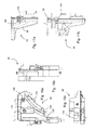
Fig. 18a shows a detail view of the filling area in exploded view as a detail A from Fig. 4 and as already described above. Fig. 18b again shows the filling area for the reservoir 62 with the condensate drawer 302 being extracted and the lid 40 being open. It shows the embodiment where the filter opening 44 is separate from the filling opening separated by a rib and wherein the filling inlet 136 of the unit 70 is just below the filling opening 46 and the filter access 134 of unit 70 is just below the filter opening 44. The filter switch 192 in Fig. 18b is at the left position within the filter access or opening 134, which means that a filer valve 198 is closed, while in Fig. 18c the filter switch 192 is in a middle position of the filter access 134 such that the filter valve 198 is open.
-
Figs. 19a and 19b are detailed cross-sectional views through the reservoir inlet unit 70 in the mounted state, corresponding to Figs. 18b and c, respectively, wherein in Fig. 19a the filter valve 198 is open, while it is closed in Fig. 19b. The cross-sections of Fig. 19a and b are taken in a plane parallel to the front of the dryer through the center of unit 70, wherein the section plane is a vertical plane. The filter housing 130 and the filter 190 housed therein are shown in cross-section, wherein the filter extends in vertical direction and basically has rotational symmetry in a horizontal section plane. At the upper region the filter 190 has a coarse filter grid 194 forming a cylindrical basket at the upper end. A fine filter mesh (not shown) is supported by the coarse filter grid 194, wherein the fine filter mesh is adapted to filter the fluff out of the condensate water passing the filter 190. The filter has a round passage or opening 196 which is arranged neighboring to the opening for the condensate coupling 106 which is protruding at the rear side of unit 70. Thus, no rib of the coarse filter grid 194 crosses the opening for the connector 106 and the flow resistance for the condensate water coming from the inside volume of the filter passing towards the connector 106 into the reservoir 62 is minimized.
-
At the lower end the filter housing 130 has a section with a lower diameter over which the upper end of the riser pipe 82 is drawn. Thus, the inner of the riser pipe 82 communicates with passages 208 formed at the lower end of the filter 190 between a valve seat 206 and a valve head 200 of the filter valve 198. Fig. 19a shows the valve 198 in the open state such that the passages 208 are open (the filter switch 192 is in the left position when seen in Fig. 19a). In Fig. 19b the passages 208 are closed as the valve seat 206 abuts against an O-ring 202 arranged at the valve head 200. In this position the filter switch 192 is at the right position (in the middle position within the filter access 134). In the closed valve state no condensate water pumped from the condensate pump unit 92 enters into the inner volume or space 214 of filter 190 and no filtered condensate water is flowing into reservoir 62. In the opened valve state (Fig. 19a) the condensate water coming from the pump unit 92 enters into the filter housing 130 and the interior 214 of filter 190 through passages 208 and flows upwards through the fine filter and filter grid 194 such that filtered condensate water is flowing in the space 216 between the outside of fine filter and filter grid 194 and inside of filter housing 130 from where it leaves through the condensate coupling 106.
-
During phases in which no condensate water is pumped through filter 130, fluff filtered by the filter may sink down towards the filter valve 198 where it may eventually block or prevent a proper closing and sealing between the valve 206 and the valve head 200 (at the O-ring 202). To avoid such blocking, the valve head 200 has a collector recess 210 which is arranged lower than the valve head 200 such that fluff or other debris released from the inside of the fine filter collects there without blocking the valve seats. At the upper end of filter housing 130 an O-ring 212 seals the cylindrical ring gap between the outside of the fine mesh (outer space 216) and filter grid 194 and the inside of filter housing 130 such that no unfiltered condensate water can pass the filter towards the reservoir 62 or towards the filter access region 134.
-
In the lower section of the filter 190 a helix-shaped spring 204 is arranged between the outside of filter 190 and the inside of filter housing 130. The spring 204 is biased when the valve is open. When filter switch 192 is shifted to the right side (Fig. 19b), the compression force compressing spring 204 is released and the spring 204 lifts the lower section of the filter (the cylindrical pipe section below the filter grid 194) such that the valve 198 is closed.
-
The top end of filter 190 above the filter grid 194 is formed by the filter cap 217 which provides a hinge and cam connection 218 to a cam 220 which is formed at the lower side of filter switch 192. The cam 220 has a cam curve 222 which interacts with pins arranged at the filter cap 217. When the filter 192 is in the left position, a lower section of cam curve 222 acts on the pins of the filter cap 217 (not shown) and presses the filter 190 to its lowest position within filter housing 130 such that the valve 198 is open. When the filter switch 192 is moved to its right position as shown in Fig. 19b, the pins at the filter 217 move upwards along the cam curve 222 due to the bias force of spring 204. Along this cam curve movement of filter 190 the valve 198 comes to its closed position such that no condensate water enters through passages 208 into filter 190. In this position and orientation of filter switch 192, the filter 190 is fixed in its closed position. If starting from the position in Fig. 19b, the filter switch is swung upward with the rotation axis at the pins of the filter cap 217, the filter switch 192 is released from its position within the filter access 134 and the filter switch 192 can be pulled upwards, thereby pulling filter 190 out of the filter housing 130 for cleaning the fine mesh and filter grid 194 from fluff and debris. Thus filter switch 192 also serves as handle or grip for removing the upper filter part from or insert it into the filter housing 130. When filter 190 is removed from filter housing 130, the lower cylindrical part or piston 224 that is surrounded by the spring 204 remains within the filter housing 130 such that the valve portion of the filter is still within filter housing 130 such as to close the valve 198 with the upper portion of filter removed.
-
When the upper section of the filter 190 is removed from filter housing 130 or when the filter 192 is in the position of Fig. 19b (valve 198 closed), no filtered condensate water is delivered to reservoir 62 and the user can manually fill reservoir 62 by supplying water or another liquid through the filling inlet 136. This gives the user the possibility to exclude condensate water from being supplied to the steam generation unit 140. Instead of filling water or decalcified water into the reservoir, the user may also fill in water with an additive or an additive liquid as such into the reservoir. The additive or additive liquid may be for example a treatment agent for dry cleaning, for waterproofing the laundry, for disinfecting the laundry, for softening the laundry or the like.
-
Fig. 6 shows the cross-section through unit 70 along the section line A-A in Fig. 5. The cross-section is taken through the center of filter 190 and filter housing 130. The cross-section is in a vertical plane perpendicular to the front of the dryer 2. Here it can be seen that the opening 196 of the filter grid 194 overlaps or coincides with the opening of the condensate plug 132. As the other filter grid 194 also the opening 196 in the coarse filter grid 194 is covered by the fine mesh of the filter.
-
Fig. 20a and 20b show top views to the front frame 30 and the filling area and filter access 134 of the reservoir inlet unit 70 as described above.
-
Returning now to Figs. 12 and 13, more details of steam generator 140 are described now. The steam generator 140 is arranged at the upper side of the upper shell or upper cover of the battery channel 78. The generator 140 has a heater body 142 for heating the liquid supplied from reservoir 62, wherein the heater body 142 is of the continuous-flow heater type in this embodiment, which only heats small amounts of liquid in a pipe leading through the heater. However, the steam generator 140 may also be a boiler-type steam generator having a container with a heater inside or outside the container to heat up larger amounts of liquid therein. An inlet 144 of the heater is connected to a pump 148 which in turn is connected to the feed pipe 84 coming from reservoir 62. Pump 148 has dosing function in that it pumps an amount of liquid into the heater body 142 in a controlled way (closed loop control or open loop control provided by control unit 300) such as to guarantee that nearly droplet-free steam leaves the heater body 142. Instead of pump 148 a controlled valve could also be provided to dose the liquid amount to be supplied to the heater 142. The heater body 142 has a steam outlet 146 where the steam generated in the heater body 142 exits towards the laundry storing compartment.
-
In the embodiment shown, the steam generator unit 140 uses an inline or flow-through heater in which the water is heated and evaporated to steam while the water is flowing through the heater. However in an embodiment a boiler-type steam generator may be used in which an amount of water is supplied to a boiler container and is heated therein to generate the steam which is drained or exhausted from the liquid surface to the outlet of the boiler chamber.
-
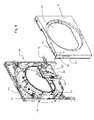
Figs. 12 and 13 further show at the rear end of the upper section or upper cover of the base or battery top cover 230 a wheel bearing 232 on which a wheel (not shown) is rotatably mounted at wheel axis 234. Only one of four wheel bearings with wheels is shown on which the cylindrically-shaped drum 20 is rotatably supported. The rotatable drum is open at the front and rear side, which are closed to form the laundry storing compartment by the compartment back wall 26 and the back side of the front frame and the loading door. At the back side of the front frame 30 and at the front side of compartment back wall 26 sealing structures are arranged, to which the front and rear edges of the drum are provided in a mating manner to each other to form a sealing to prevent escape of laundry or process air from the laundry storing compartment. Figs. 29 and 30 show rear perspective views of the drum 20 and the front frame 30, wherein the front edge 21a and the rear edge 21b of the cylindrical drum wall are shown. In Fig. 30 a portion of the drum cylinder is cut out to have a cross-sectional view to a drum sealing 236 provided at the front side of the drum. The drum sealing 236 is shown in more detail in Fig. 31 which is similar to the cross section detail B of Fig. 30. The front edge 21a of drum 20 extends into a groove 238 formed at the backside of front frame 30. For sealing between the groove 238 and the front edge 21a an O-ring 240 having a rectangular cross-section is inserted into groove and abuts against the front edge. A similar sealing arrangement is provided at the front side of the rear frame 31 or the compartment back wall 26. The circular groove for receiving the rear edge 21b of drum is arranged at the rear frame 31 or the back wall 26 and an O-ring is inserted therein similar to O-ring 240 for sealing against process air or steam escape from the drum to the outside thereof or against invading of outside air into the drum. Additionally the sealing arrangement prevents jamming of laundry in the junction between drum and back wall 26 or loading opening frame and prevents escape of steam from the drum interior.
-
Fig. 21 shows a detailed view of a steam inlet unit 250 with the cone 252 corresponding to an enlargement of the circle section A in Fig. 12. Steam outlets 254 are provided at the free-standing end or the front section of cone 252 at the upper side thereof. It is to be noted that the outlets 254 do not supply processing air to the laundry storing compartment and that the rear wall openings 28 do not supply steam into the laundry storing compartment.
-
Fig. 22 shows a cross-section along the section line B-B in Fig. 11 such that the front frame 30 and the rear frame 31 are vertically intersected in their respective centers where the steam inlet unit 250 is mounted at the center of the compartment back wall 26 which is mounted at the rear frame 31. The rear frame 31 preferably is formed of a plate-material, like a metal plate, which is structured by pressing. The center region of the rear frame 31 forms a back channel wall 256 or back shell of a process air rear channel 258 which extends from the bottom section to a center region of the dryer back side. The process air rear channel 258 is formed between the inner side of back channel wall 256 and the rear side of the compartment back wall 26 which is mounted to the rear frame 31. The process air rear channel 258 guides process air from a blower, which is arranged in a base section of the dryer, upward toward the center of the dryer at the back side where the process air enters the laundry storing chamber through the air inlet openings 28 (compare Fig. 2). Fig. 22 further shows the inner side of the upper battery channel 78. The battery channel 78 is formed between an upper and lower shell forming the basement of the dryer, wherein the figures show only the upper shell as battery top cover 230. The inner side of the battery channel is here shown by battery inner wall 260 of the basement upper shell 230 (lower basement shell or lower battery cover is not shown).
-
Fig. 23 shows an enlarged view of the steam inlet unit 250 arranged at the rear frame corresponding to the detail of circle C in Fig. 22. In the vertical cross-section plane from the front to the back side it is seen that the cone 252 has a hollow interior wherein a separation chamber 264 is arranged at the front or free-standing end section of cone 252. The separation chamber 264 is designed to separate steam, which is supplied into the separation chamber 264, from droplets that are transported with the steam into the chamber or which are formed at or in the separation chamber 264. In the shown embodiment the separation chamber is defined at the front end side by the inner wall of the cone 252, while the back side of the chamber is restricted by a partition wall 278. Due to the partition wall the steam does not distribute in all the volume of the cone, but only in the separation chamber 264 from where it enters into the laundry treatment compartment formed by the drum and the front and rear walls thereof through the steam outlets 254. By this projected or overhanging construction where the steam outlets 254 are distant or offset to the walls defining the laundry storing compartment, the steam is introduced closer and more efficient to the inner or center of the storing compartment which results in a more efficient steam distribution in the compartment volume.
-
Steam is supplied into separation chamber via an inlet line 266 which has an opening in the partition wall 278. An outlet line 268 is guiding condensed steam or collected droplets to the outside of the separation chamber 264. At the back side of the partition wall 278 the lines 266 and 268 are formed as a channel feed through 270 which is guided through the process air rear channel 258 to the back side of the back channel wall 256. The feed through 270 guides the two lines 266, 268 separately to the back side such that steam can flow from the back side of wall or shell 256 to the inside of chamber 246 and condensate water is guided out from chamber 264 through the channel 258 to the back side of the wall 256, i.e. backside of rear frame 31. Correspondingly, the feed through 270 has a steam inlet 273 to line 266 connecting to steam inlet 272 at chamber 264. And feed through 270 has a condensate outlet 274 at chamber 264 and a rear outlet 275 at the rear end of feed through 270. Preferably inlet 272 is arranged above outlet 274, however they may also be arranged side by side. Also they need not end at the same plane and can be axially (with respect to the opening plane) offset to each other. I.e. inlet 272 may protrude farther into chamber 264 than outlet 274. Additionally a droplet deflector or catcher may be assigned to the steam inlet 272 which assists in separating droplets from the introduced steam. For example a shield or plate may be arranged between the inlet 272 and the outlets 254 which the steam on its path from 272 has to bypass before reaching outlets 254.
-
In the embodiment shown, a rear connector 286 is mounted at the back channel wall 256 such that it receives the rear end of the feed through 270. The rear connector 286 has a recess which mates in contour to the outer contour of feed through 270 with O-rings 276 arranged between the outside of feed through 270 and the inside of the recess such to seal the lines 266 and 268 at the rear end. The rear connector 286 has a steam passage 288 through which steam is supplied to the inlet line 266 and has a condensate passage 290 which receives the condensate from the outlet line 268.
-
The bottom of the separation chamber 264 is defined or restricted by a collector plate 280 which may be formed as part of the cone 252, as part of the partition wall 278 or may be formed as a separate part which is mounted when assembling the steam inlet unit 250. The collector 280 collects the condensate water and guides it to the condensate outlet 274 in the partition wall 278 to guide it out of the cone via the outlet line 268. The partition wall 278 in this embodiment is monolithically formed with the channel feed through 270 (for example in a blow mold or injection mold process), it may be part of the cone 252 or it may be a separate element which is mounted to feed through 270 or to cone 252.
-
The cone 252 is mounted to the front side of the rear frame 31 using a mounting flange 282 which is glued, screwed, welded or otherwise mounted to the compartment back wall 26. The mounting flange 282 has a bayonet connector 283 such as to mount the cone 252 on the flange 282 in a bayonet lock. However, other ways of mounting cone on the flange may be provided or the flange 282 may be omitted and the cone 252 may be directly mounted, welded, glued or fixed to the back wall 26.
-
Fig. 24 shows the steam inlet unit 250 in an exploded view without showing the back frame 31 (back channel wall 256) and the compartment back wall 26. In this view, the notches of the bayonet connector 283 and a latch 285 for locking cone 252 in the rotation end position of the bayonet connector 283 are shown. As can be seen in the exploded view of Fig. 24 and from cross-section in Fig. 23, spacer bars 284 extend from the back side of the bayonet connector 283. The length or depth of the spacer bars 284 is selected such that they bridge the depth of the process air rear channel 258 to prevent a narrowing of the rear channel during drying operation where the laundry may press against the cone 252, or to stabilize the rear channel for example when the dryer is placed in position in the user's home.
-
Fig. 25 shows a rear perspective view of the dryer 2, where the lower section of the base unit and the right side wall are removed. The rear connector 286 is mounted on the rear side of back channel wall 256 and a steam pipe 292 is fluidly connected with the steam passage 288 in the rear connector 286. The steam pipe 292 in turn is connected to the steam outlet 146 of the steam generator 140 shown in Fig. 13. Thus, steam can be supplied from the steam generator 140 through steam pipe 292, through rear connector 286, through inlet line 266 and steam inlet 272 into separation chamber 264 and from there to the interior of drum 20. Further, a condensate pipe 294 is fluidly connected to the condensate passage 290 of rear connector 286 and guides the condensate water down along the pipe 294 into the condensate container 304 of the condensate pump unit 92 arranged at the back end of the battery channel (compare Fig. 13).
-
Fig. 26 is an enlarged view of the detail B of Fig. 25 where the mounting of pipes 286 and 294 to respective stubs of the rear connector 286 can be seen.
-
Fig. 27 shows a front view of the steam inlet unit 250 in the assembled state, but with the rear frame 31 with its center portion back channel wall 256 removed.
-
Fig. 28 shows as a block diagram some of the components of the dryer 2 and their mutual functional relation. The reservoir 62 holds liquid which preferably is water. The liquid level in reservoir 62 can be visually detected by a user through the level window 68 arranged at a (front) side wall of the reservoir. For improving visual detection, the floater 116 is floating at the liquid surface where it is shifted up and down along its moving path within the floater cage. When the level drops below the range or to the lower end of the range which is observable through window 68, the "liquid low" level can be detected by detector unit 126. The detector unit provides a respective signal to the control unit 300 of the dryer 2. If required, sensor power supply voltage is delivered from control unit 300 to sensor 126 and/or power for operating an illumination device (e.g. LED or lamp) to illuminate the reservoir such that the liquid level can be more easily detected by the user. In an embodiment the detector unit 126 has the control line or has an additional control line connected to the steam generator 140 to have a security switch-off provided to heater body 142 in case of low water level. This serves as security measure at a control level below the controller 300.
-
The user can manually fill the reservoir 62 through filling inlet 136. In normal operation, condensate produced by the laundry drying process is sufficient to provide enough liquid to reservoir 62, wherein the condensate is provided from condensate pump unit 92 through the valve 198 and filter 190 to the interior or reservoir 62. Filling inlet 136, valve 198 and filter 190 are provided in the reservoir inlet unit 70 in this embodiment, however, these elements can all or partially be integrated in the body (e.g. one of the shells 64, 66) of reservoir 62. The user can manually close valve 198 to stop condensate supply to the reservoir such that the filling of the reservoir is made through filling inlet 136 only manually. Valve 198 may be integrated in unit 70 or directly in the reservoir 62 or it may be arranged at another position in the supply line from the condensate pump unit 92 to the reservoir 62. Valve may for example be a controllable valve, like a solenoid valve which is controlled (closed and opened) under the control of control unit 300.
-
Condensate pump unit 92 is fluidly connected to the battery channel 78 to collect the condensate water which is formed during the drying process at the heat exchanger where the process air is cooled down to remove air humidity therein. Optionally, the condensate tank 304 in the condensate pump unit 92 also collects condensate that has condensed in the steam inlet unit 250 and/or which comes along overflow pipe 88 from reservoir 62. The liquid from steam inlet unit 250 and/or from reservoir 62 can be supplied directly into the condensate tank 304 or via the battery channel 78 where it may be introduced at any arbitrary position. The pump 306 sucks in condensate from condensate tank 304 and pumps it through the branch which has the first pump outlet 94 to the riser pipe 82 for supplying condensate into reservoir 62, and through the second pump outlet 96 through a drain pipe 83 into the drawer 302. As mentioned above, a second maximum level detector may be associated to the tank 304 to detect that condensate rises to or above a maximum level of normal operation where all condensate can be pumped to drawer 302. Thus when the second maximum level is reached, the abnormal state indicated thereby may have its origin in the drawer capacity being full and no condensate can be drained by pump 306 into the drawer (or the reservoir 62). Then at least the drying process is stopped to prevent further formation of condensate and the user is informed that the drawer 302 has to be emptied. In an alternative embodiment or additionally, drawer 302 has another liquid level indicator which sends a signal to control unit 300 to indicate to the user that the condensate collected in drawer 302 has to be manually removed. As described before, the branch 94/96 splits the condensate flow rate such that e.g. about one third is supplied to the reservoir 62 and two thirds are supplied to drawer 302.
-
Through feed pipe 84 the liquid from reservoir 62 is supplied to the pump 148 in the steam generator 140 which supplies controllable amounts of liquid using a control operation of the control unit 300 for the pump 148 operation. The liquid from pump is supplied into the heater body 142. The steam from heater body 142 is supplied through steam pipe 292 into the steam inlet unit 250 from where the steam is blown through cone 252 to the interior of drum 20. Energizing and de-energizing of the heater 142 is made via control unit 300 which also monitors overheating and/or overpressure in the heater body 142.
-
User program selections and program option selections are made via the input section 16 which is connected to control unit 300, wherein the input section further indicates a status of the dryer, like selected program, remaining drying time, or any malfunction like low liquid level in reservoir 62, over-temperature in steam generator 140 or drawer 302 full with condensate to be removed.
-
Reference Numeral List:
- 2
- condenser dryer
- 4
- top cover
- 6
- left cover
- 8
- front cover
- 10
- loading opening
- 12
- front top panel
- 13
- drawer portion
- 14
- drawer cover
- 15a
- condensate drawer
- 15b
- drawer housing
- 16
- input section
- 18
- loading frame
- 20
- drum
- 21a
- front edge
- 21b
- rear edge
- 22
- window panel
- 24
- drawer handle
- 26
- compartment back wall
- 28
- air inlet openings
- 30
- front frame
- 31
- rear frame
- 32
- filter compartment / process air channel
- 34
- fluff filter
- 36
- drawer opening
- 38
- user filling section
- 40
- lid
- 42
- covered section
- 44
- filter opening
- 46
- filling opening
- 48
- hinge
- 50
- front cover top opening
- 52
- front cover window opening
- 60
- reservoir unit
- 62
- reservoir
- 64
- front (first) shell
- 66
- rear (second) shell
- 68
- level window
- 70
- reservoir inlet unit
- 72
- reservoir mounting bracket
- 74
- riser feed through
- 75
- supply feed recess
- 76
- base section
- 78
- battery channel (upper portion in cover shell)
- 82
- riser pipe
- 83
- drain pipe
- 84
- feed pipe
- 86
- overflow feed through
- 88
- overflow pipe
- 89
- fixing clamps
- 90
- battery inlet
- 92
- condensate pump unit
- 94
- first pump outlet
- 96
- second pump outlet
- 98
- filter inlet
- 100
- feed outlet
- 102
- overflow outlet
- 104
- seal
- 106
- condensate coupling
- 108
- filling coupling
- 110
- inlet unit recess
- 112
- pipe recess
- 114
- mounting grooves
- 115
- front frame rib
- 116, 116'
- floater
- 116a, b, c
- floater positions
- 117, 117'
- magnet head
- 118
- floater cam
- 120
- window section
- 121
- slanted section
- 122
- detector section
- 124
- floater cage
- 126
- detector unit
- 128
- cable clip
- 130
- filter housing
- 132
- condensate plug
- 134
- filter access
- 136
- filling inlet
- 138
- filling plug
- 140
- steam generator
- 142
- heater body
- 144
- inlet
- 146
- steam outlet
- 148
- pump
- 160
- printed circuit board
- 162
- REED sensor
- 164
- socket
- 166
- protrusion
- 168
- seat
- 170
- first bracket
- 172
- second bracket
- 174
- detent
- 176
- shield
- 178
- roof
- 180
- side wall
- 182
- deflector
- 190
- filter
- 192
- filter switch
- 194
- filter grid
- 196
- opening
- 198
- filter valve
- 200
- valve head
- 202
- O-ring
- 204
- spring
- 206
- valve seat
- 208
- passage
- 210
- collector
- 212
- O-ring
- 214
- inner space
- 216
- outer space
- 217
- filter cap
- 218
- hinge connection
- 220
- cam
- 222
- cam curve
- 224
- cylinder piston
- 230
- battery top cover
- 232
- wheel bearing
- 234
- wheel axis
- 236
- drum sealing
- 238
- groove
- 240
- O-ring
- 250
- steam inlet unit
- 252
- cone
- 254
- steam outlet
- 256
- back channel wall
- 258
- process air rear channel
- 260
- battery inner wall
- 264
- separation chamber
- 266
- inlet line
- 268
- outlet line
- 270
- channel feed through
- 272
- steam inlet
- 273
- rear inlet
- 274
- condensate outlet
- 275
- rear outlet
- 276
- O-ring
- 278
- partition wall
- 280
- collector
- 282
- mounting flange
- 283
- bayonet connector
- 284
- spacer bar
- 285
- latch
- 286
- rear connector
- 288
- steam passage
- 290
- condensate passage
- 292
- steam pipe
- 294
- condensate pipe
- 300
- control unit
- 302
- condensate collector/drawer
- 304
- condensate tank
- 306
- pump