EP2610392A1 - Appareil domestique pour sécher le linge doté d'une unité de buse de vapeur - Google Patents
Appareil domestique pour sécher le linge doté d'une unité de buse de vapeur Download PDFInfo
- Publication number
- EP2610392A1 EP2610392A1 EP11195958.1A EP11195958A EP2610392A1 EP 2610392 A1 EP2610392 A1 EP 2610392A1 EP 11195958 A EP11195958 A EP 11195958A EP 2610392 A1 EP2610392 A1 EP 2610392A1
- Authority
- EP
- European Patent Office
- Prior art keywords
- laundry
- steam
- nozzle body
- condensate
- unit
- Prior art date
- Legal status (The legal status is an assumption and is not a legal conclusion. Google has not performed a legal analysis and makes no representation as to the accuracy of the status listed.)
- Withdrawn
Links
Images


Classifications
-
- D—TEXTILES; PAPER
- D06—TREATMENT OF TEXTILES OR THE LIKE; LAUNDERING; FLEXIBLE MATERIALS NOT OTHERWISE PROVIDED FOR
- D06F—LAUNDERING, DRYING, IRONING, PRESSING OR FOLDING TEXTILE ARTICLES
- D06F58/00—Domestic laundry dryers
- D06F58/02—Domestic laundry dryers having dryer drums rotating about a horizontal axis
- D06F58/04—Details
-
- D—TEXTILES; PAPER
- D06—TREATMENT OF TEXTILES OR THE LIKE; LAUNDERING; FLEXIBLE MATERIALS NOT OTHERWISE PROVIDED FOR
- D06F—LAUNDERING, DRYING, IRONING, PRESSING OR FOLDING TEXTILE ARTICLES
- D06F58/00—Domestic laundry dryers
- D06F58/20—General details of domestic laundry dryers
- D06F58/203—Laundry conditioning arrangements
-
- D—TEXTILES; PAPER
- D06—TREATMENT OF TEXTILES OR THE LIKE; LAUNDERING; FLEXIBLE MATERIALS NOT OTHERWISE PROVIDED FOR
- D06F—LAUNDERING, DRYING, IRONING, PRESSING OR FOLDING TEXTILE ARTICLES
- D06F58/00—Domestic laundry dryers
- D06F58/20—General details of domestic laundry dryers
-
- D—TEXTILES; PAPER
- D06—TREATMENT OF TEXTILES OR THE LIKE; LAUNDERING; FLEXIBLE MATERIALS NOT OTHERWISE PROVIDED FOR
- D06F—LAUNDERING, DRYING, IRONING, PRESSING OR FOLDING TEXTILE ARTICLES
- D06F58/00—Domestic laundry dryers
- D06F58/20—General details of domestic laundry dryers
- D06F58/24—Condensing arrangements
Definitions
- the nozzle body has one or a plurality of nozzle outlets, wherein the majority of the nozzle outlets or all of the (plurality) of nozzle outlets are (essentially) arranged at the upper half of the nozzle body.
- the 'facing upward' of the nozzles at the nozzle body directs the steam into a volume region of the storing compartment where the steam can distribute without less obstacles (laundry) and at the same time light weight steam escapes from the nozzle body while heavy droplets are withhold in the nozzle body to prevent direct contact between hot liquid and laundry.
- the projection of the nozzle body provides a detangling function for the laundry or reduces tangling of the laundry during any treatment process in which the drum is rotated.
- Such processes are for example a drying process and the steam treatment process in which the drum is rotated at least temporally.
- the projecting nozzle body deflects the laundry during tumbling and thus redistributes the laundry to avoid clustering and to provide a slackening.
- the nozzle body is hollow and comprises a or the nozzle rear wall which defines the hollow internal volume in the nozzle body and which comprises a steam inlet to the hollow internal volume or a steam inlet to and a condensate outlet from the hollow internal volume, wherein the nozzle body and the nozzle rear wall are formed of two separate parts that are fitted or fixed together.
- the steam inlet fluidly connects the hollow internal volume to the steam generating unit and/or the liquid outlet is adapted to drain liquid or water from the hollow internal volume.
- the steam inlet is arranged above the liquid outlet or the steam inlet is arranged at the same or essentially the same horizontal level.
- the dryer may further comprise a back frame extending from a base region to an upper region at the back region of the dryer.
- the back frame comprises one, two or more passages or openings adapted to guide one or both of a steam supply line to or a condensate back flow line from the nozzle unit through the back frame.
- the invention can also be implemented in any other type of dryer or in any other type of domestic appliance.
- the home appliance may be a washing machine having drying function with or without a heat exchanger or condensing unit.
- the following groups or sub-units of the domestic appliance can be implemented individually in the domestic appliance or in any combination of the groups:
- Fig. 1 shows a front perspective view of a partially disassembled condenser dryer that uses a heat pump system.
- the outer appearance of the depicted dryer 2 is defined by a top cover 4, a left cover or wall 6, a front cover 8 having a loading opening 10 and a front top panel 12.
- the front top panel 12 frames a drawer cover 14, wherein here the drawer has a condensate container that is completely pushed in a drawer compartment located at the upper part of the dryer.
- the right portion of the front top panel 12 forms an input section 16 wherein here the details of the input section 16 are not shown (like indicators, a display, switches and so on).
- Back wall 26 is preferably provided as a separate element to the rear frame 31, formed for example from a metal plate.
- the rotation axis of the drum is horizontal, however, the rotation axis may be inclined with respect to the horizontal axis or may be even vertical with some modifications to the shown embodiment, however without the requirement to modify other groups of the dryer.
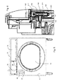
- Fig. 29 shows in perspective back view the drum 20, the front frame 30 and the drawer housing or compartment 15a in which the condensate drawer 15a is completely inserted.
- a window panel 22 is inserted into a front cover window opening 52 ( Fig. 4 ).
- the window opening 52 and the window panel 22 allow visual inspection into the inside of the dryer outer body where a liquid reservoir 62 is arranged to check the liquid level (see more detail below).
- arranging the user filling section 38 in a lower frame portion of the drawer opening 36 allows a simple modification of standardized dryers for models that use steam generation and models that do not use steam generation.
- models with steam generation the front top panel 12 with the user filling section 38 is used, while for models without steam generation there is no user filling section 38 and instead the lower portion of the frame of the drawer opening 36 is just a flat plate without any openings and/or lid.
- the opening 50 overlaps with the opening 44/46 when the front top panel 12 is mounted on the front frame 30, wherein the lower frame of the drawer opening 36 is arranged close to or abutting to and parallel to the front cover top frame.
- the front top panel 12, more specifically the drawer portion 13 forming the panel frame around drawer opening 36 just has a recess or gap over the filling inlet 136 and/or filter access 134 instead of the separate openings 44 and 46 in the drawer portion 13.
- the window panel 22 is removed such that one can see the front cover window opening 52 which allows a view to the interior of the dryer just behind the front cover 8 where the reservoir 62 is arranged behind the window opening 52.
- the dryer models which use mainly the same components (for example the heat pump system, the base section, the front frame 30, the rear frame 31 and the drum) can be modified from between steam type by exchanging the front cover 8 having the opening 50 and 52 and the front cover having neither opening 50 nor 52. Also the front top panel 12 having the user filling section 38 or not can be exchanged between the models using the same standardized dryer (home appliance platform). In a modification the front cover 8 shown in Fig.
- Fig. 18a shows the section A indicated in Fig. 4 in more detail.
- Fig. 5 shows a front view of the front frame 30, the front cover 8 and the front top panel 12 without details of the input section 16 and with the condensate drawer removed such that the drawer opening 36 to the drawer compartment can be seen.
- a level window 68 of the reservoir 62 can be seen.
- the section A-A of Fig. 5 is shown in Fig. 6 which will be described in detail below.
- Fig. 7 shows in top view from left to right the front frame 30, the reservoir 62, a reservoir inlet unit 70, the front cover 8 and the window panel 22.
- the reservoir 62 and the reservoir inlet unit 70 form together a reservoir unit 60 which has the function to store water to be supplied to a steam generator, to receive water filled in by a user manually and to filter condensate water which is pumped from a condensate collector of a condensate unit 92 to the reservoir 62.
- the reservoir 62 is forming a container composed of a front or first shell 64 and a rear or second shell 66 which are glued, welded, ultrasonic welded or otherwise mounted together.
- the reservoir inlet unit 70 is a pluggable component that can be plugged into the reservoir 62 and provides the manual filling, condensate filling and filtering function to the reservoir 62.
- the reservoir inlet unit 70 has a condensate plug 132 that is protruding from the (back)surface of the unit 70 and is adapted to be inserted in a respective coupling or socket 106 ( Fig. 15a ) at the front side of the front shell 64.
- Condensate which was pumped from a condensate reservoir to the filter in the unit 70 exits the unit 70 towards the interior of reservoir 62 during a filling process for filling the reservoir with condensate water.
- a second plug is a filling plug 138 which protrudes at the back side of unit 70 and is adapted to be inserted in a respective coupling or socket 108 at the front shell 64. Liquid filled in manually into the unit 70 flows into the reservoir 62 via the filling plug 138.
- the individual elements or groups of elements of the reservoir inlet unit 70 may be integrated into the front and/or rear shell 64, 66 of the reservoir 62.
- the reservoir 62 and the reservoir inlet unit 70 are provided as two separate components in this embodiment for simplifying the manufacturing process of the front and rear shells 64, 66, as otherwise a more complex molding process would be required to integrate the functionality of unit 70 into the reservoir 62.
- the reservoir may be easily modified, for example in providing the shell separation in a horizontal plane instead of a vertical plane and the filter and filling openings may be arranged then in the upper shell for example.
- Fig. 8 shows an exploded perspective view of the front frame 30, the reservoir 62, the filling unit 70, the front cover 8 and the panel 22.
- the front frame 30 has a reservoir mounting bracket 72 adapted to receive reservoir 62.
- Fig. 9 shows the state in which the reservoir 62 is mounted at the front side of the front frame 30 and the unit 70 is mounted at the front side of reservoir 62.
- the reservoir and the unit 70 are dimensioned such that these make use of the hollow space or dead volume which is present in the dryer between the front side of front frame 30 and the back side of the front cover 8.
- the structure of the front frame 30 is optimized for the supporting function of the frame in respect of mounting the components and cover elements of the dryer and the structure is further optimized and adapted such as to receive the reservoir unit 60 without compromising the required mechanical stability and by integrating the reservoir unit 60 under reduction of extra-space for it.
- the back side of reservoir 62 (here the rear shell 66) is adapted in a way to match the front structure of the front frame 30 and distribute the volume required for containing the liquid in the reservoir to areas and spaces between the frame 30 and the cover 8 where the respective space is available under preservation of the mechanical function of the front frame design elements and the front cover 8.
- the front frame 30 can be used in unmodified form as a platform element for a dryer model that has a reservoir unit (e.g. for the steam generation unit) as well as for a dryer model that does not make use of the reservoir unit (and the steam generation and steam treatment of the laundry).
- the front frame 30 is adapted to receive the reservoir unit (at least partially) such that no defective mechanical properties for the general purpose function of the front frame 30 are implemented, for example a riser feed through 74 is provided in a base area of the front frame without having an effect on its structural stability, while the feed through 74 provides an important liquid passage and/or pipe supporting function without requiring additional elements. This correspondingly applies for the overflow feed through 86 shown in Fig. 14 .
- Figs. 9 and 10 further show the arrangement of the fluff filter 34 in the process air channel section which is formed in the lower region of the front frame 30.
- the process air that has crossed the drum 20 is leaving the laundry treatment compartment at the lower section just in front of the loading frame 18 which is closed by a loading door through the channel section formed in frame 30 towards a battery channel 78 ( Fig 11 shows upper part of battery channel as part of the upper basement shell or battery top cover 230) which provides another process air channel section formed in the base unit of the drum.
- the air in the process air channel section of the frame 30 is passing the fluff filter 34 to remove the fluff.
- Fluff filter 34 can be taken out of the process air channel section by pulling it upward as is indicated by the filter position shown in Fig. 9 as compared to the one in Fig. 10 , where the filter is completely inserted for proper operation.
- Fig. 11 shows a front view of the dryer with cover 8 and top cover 4 as well as left cover 6 removed and without a lower portion of the base section.
- On the bottom an upper portion or cover shell 230 of the base section 76 is shown which includes the upper portion 78 of the battery channel where the process air enters which comes through the process air channel section going through the front frame 30.
- the fluff filter 34 is also removed in this figure.
- the reservoir unit 60 is mounted and the pipes connecting the unit to other elements are shown.
- a riser pipe 82 comes from the back side of the front frame 30 and is guided through the riser feed through 74 from where it goes upward to a filter inlet 98 ( Fig. 15b ) of the reservoir inlet unit 70.
- a feed pipe 84 is connected to a feed outlet 100 at the lower end of reservoir 62 and goes down at the front side of frame 30 and through a supply feed recess 75 formed at the lower edge of front frame 30.
- the riser pipe 82 and the feed pipe 84 are clamped by clamps 89 mounted at the front side of frame 30.
- the cross-sectional view indicated by section B-B in Fig. 11 is shown in Fig. 22 (similarly in Fig. 13 ).
- Fig. 14 is a view to the back side of the front frame 30.
- An overflow pipe 88 is guided from an overflow feed through 86 in the upper region of the frame 30 to the lower region of the frame.
- the pipe 88 is mechanically fixed to the frame by clamps 89 provided at the backside of frame 30.
- the overflow feed through 86 is a passage from the front side to the rear side of frame 30 below the drawer opening 36 and is coinciding or overlapping with a overflow connection at the back side of the reservoir 62 (in front projection - compare overflow outlet 102 shown in Fig. 17c .)
- overflow pipe 88 The outlet of overflow pipe 88 is connected to a battery inlet 90 as can be seen from Figs. 12 and 13.
- Fig. 12 shows at 78 the upper shell of the battery channel.
- Overflow liquid that is descending in overflow pipe 88 enters the battery channel at 90 and is guided within the battery channel towards a condensate pump unit 92 where the condensate water that has condensed from the process air at the evaporator of the heat pump system is collected together with the liquid coming down the overflow pipe 88.
- the condensate pump unit 92 is assigned to the battery channel 78 and collects the condensate water and the overflow water from reservoir 62 in a condensate container (304 in Fig. 28 ).
- the pump (306 in Fig.
- the condensate pump unit 92 pumps the condensate from the condensate container to a liquid branch which has a first pump outlet 94, which is connected to the riser pipe 82, and a second pump outlet 96, which is connected to a pipe which supplies the condensate into the container (302 in Fig. 28 ) of the condensate drawer.
- the respective flow resistances from the branch 94/96 through the pipes and vertical height difference to the reservoir inlet unit 70 and the condensate drawer are designed such that about 20% to 40% of the condensate water is supplied to reservoir 62 via unit 70 and the remainder of the condensate water is pumped to the condensate drawer (unless the filter valve 198 of the filter 190 in the reservoir inlet unit 70 is closed).
- the water consumed by steam generator 140 is less than the condensate water which is pumped from the condensate pump unit 92 into the reservoir 62.
- the condensate pump unit 92 provides a signal initiated by a second maximum level in the condensate tank (304 in Fig. 28 ) to the control unit 300 which then stops operation of the dryer and/or stops a laundry drying process in which the condensate is formed by the laundry drying.
- the control unit 300 waits for the user draining the condensate drawer 15a/302 such that pump 306 can again pump condensate into the condensate tank of drawer 15a.
- a maximum filling level in the condensate drawer 15a/302 can be monitored instead or in addition to the second maximum level for the condensate tank 304 and the dryer or the drying process may be stopped as beforehand.
- Fig. 15a shows an exploded view of the reservoir in more detail.
- the reservoir is composed of a front shell 64 and a rear shell 66 which are to be joined together in a vertical plane.
- the feed outlet 100 which supplies the water to the steam generator 140 via pipe 84 is formed at the bottom end of the front shell 64.
- the overflow outlet 102 is formed in an upper region of rear shell 66 and is to be connected to the overflow pipe 88 which is arranged at the back side of front frame 30.
- the front shell 64 further has a condensate coupling 106 adapted to couple with the condensate plug 132 protruding at unit 70 (see Fig.
- a seal 104 is inserted which has the form of a cylindrical sleeve with a collar. After insertion of seal 104 into the respective openings, the plugs 132 and 138 as well as an adaptor pipe connecting the overflow outlet 102 to the inlet of the overflow pipe 88 through the overflow feed through 86 are inserted to provide a sealed coupling.
- an inlet unit recess 110 is formed which contour is adapted to receive a portion of the volume of reservoir inlet unit 70.
- the inlet unit recess 110 is formed such that when the unit 70 is mounted on the front shell 64, the unit 70 is received flush or nearly flush with the main front surface of front shell 64 (in this case without considering the protruding level window 68).
- a pipe recess 112 is formed which receives a filter housing 130 of unit 70 and the upper portion of the riser pipe 82 which is connected to the filter inlet 98.
- the rear shell 66 has mounting grooves 114 formed on its back side which are adapted to receive ribs 115 which are formed on the front side of front frame 30 (see Fig. 8 ) and which serve to provide mechanical stability for the front frame structure.
- the wall parts of the rear shell 66, which form the grooves 114, partially separate the internal volume of reservoir 62 such that it can be said that the volume of the reservoir is split into partial volumes fluidly connected to each other so that the different portions of the split volume fit into recesses of the front frame for minimizing the space requirement for the container 62 by using dead volume in the structure of the front frame 30.
- the reservoir For determining the liquid level within the reservoir 62, the reservoir provides the level window 68 through which a floater 116 can be visually observed by the user.
- the level is also detected electronically by using a detector unit 126 which is mounted on a side wall of the front shell 64 close to the level window 68 and adapted to detect the floater 116.
- the floater 116 is detected magnetically, using a respective sensor of the detector unit 126 (see below) and a magnet head 117 being part of the floater 116.
- the floater 116 is received in a cage 124 formed by respective portions of the front and rear shell 64, 66.
- the cage 124 On the side of the front shell 64 the cage 124 is formed by a channel that is open at one side (here the back side) and on the side of the rear shell 66 the cage section is formed by a floater cam 118 which protrudes as a small rib vertically extending at the inner front side of shell 66.
- the upper section of the open channel formed in the front shell is closed by the protruding level window 68 which has a top wall section representing the upper limit.
- the front window section of window 68 forms the front wall restriction and two side walls of window 68 form the side restrictions for floater 116.
- the floater cam 118 has a window section 120 which is protruding farther from the inner surface of rear shell 66 to guide the path of the floater 116 in its level changing path within the level window inner volume.
- the cage 124 is formed of parts of the shells that have to be assembled anyway, there is no need for additional assembling steps for separately assembling the cage for the floater.
- the floater is for example inserted in the inner volume of window 68 (one cage part) and by combining the shells the cage is simultaneously closed for the floater.
- Fig. 17d shows a cross-section through the reservoir along the section line D-D as indicated in Fig. 16a .
- Fig. 17d shows the floater 116 in its upper position (116a) and in its lowest position (116b) within the floater cage 124.
- the front side with respect to reservoir 62 is shown at the right side, while the rear side is shown at the left side of Fig. 17d . So it can be seen that along the window 68 the path of floater 116 is guided parallel to window 68 and a slope is going to the recessed position within the cage 124 from the pathway going from upside to downside, wherein finally in the lowest position 116b the floater path has again a vertical direction.
- the detector unit 126 is arranged in the region of the lower position 116b.
- the floater 116 can be visually observed by the user in the normal water level range within container 62, while the electronic detection by the detector unit 126 detects the floater in or close to the lowest position to indicate the critical low water level or the run low of the water in reservoir 62.
- Fig. 16a shows a front view of the assembled reservoir 62
- Fig. 16b shows a side view
- Fig. 16c a top view of the reservoir.
- the condensate coupling 106 and the filling coupling 108 can be seen, each with one of seals 104.
- the overflow outlet 102 can be seen with the seal 104 inserted.
- FIG. 17a to 17d are vertical plane sections through reservoir
- Fig, 17e shows a horizontal plane section through the reservoir along the section line E-E in Fig. 16a . It is taken in a (vertical) height where the floater 116 has its flow path within the cage 124 that is partially formed by the level window 68. At the left side of level window 68 the section goes through the detector unit 126 which has its detector sensitive zone below the travel path of floater 116 in the floater cage 124 at floater position 116b shown in Fig. 17d .
- Fig. 17f shows an enlarged view of the level detector unit 126 taken from the area indicated by A in Fig. 15a .
- the printed circuit board 160 of the detector unit 126 is shown in the disassembled state.
- a REED sensor 162 is arranged at the PCB 160 adapted to detect the magnetic field of the magnet head 117 from floater 116 in floater position 116b (low water level).
- a socket 164 is provided at the lower end of PCB 160 adapted to couple with a connector plug arranged at the end of wires for connecting the sensor to the control unit 300 of the dryer for evaluating the signal provided by the REED sensor 162.
- the electrical wires connecting the sensor unit 126 to the control unit of the dryer are held by cable clips 128 arranged along the front side of the reservoir 62.
- the control unit 300 recognizes that the water level in the reservoir is low and upon detecting this signal the steam generation by steam generator 140 is switched off. Additional measures can be taken by the control unit upon detecting the low liquid level, for example an acoustic or visual indication can be activated to inform the user that the water level is low. Further upon detecting the low level, the control unit can stop the steam supply too during the running process and finish the running process without modification except steam supply stopped, or it can stop the running process completely or an alternative process can be run, which does not need steam treatment for the laundry. Also, the control unit can interrupt the running program and wait for replenishing the water in reservoir 62 by the user.
- any other sensor can be used that detects the magnetic field from the floater 116, for example a Hall sensor.
- the detector unit 126 can be provided with another detector detecting another feature of floater 116, for example which is adapted to detect presence or absence of the floater 116 in the region where the low level is to be detected.
- an optical sensor could be provided which detects the reflection of light emitted to the floater 116, such that the presence of the floater and absence of the floater is detected optically from the reflected light.
- an ultrasonic reflection can be detected from the floater to sense the low liquid level.
- a light source like an LED, a lamp or something else could be arranged on the detector unit 126 or its PCB 160 to illuminate at least a portion of the interior of the reservoir 62 such that the user can more easily visually recognize whether the floater 116 is in the region of the level window 68 or not.
- the seat 168 for the PCB 160 is provided at the side of the front shell 64.
- the PCB 160 has lateral protrusions 166 which are adapted to snap into latches of a second bracket 172 of the seat 168 while the opposing back side of PCB 160 is latched by elastic detents 174 provided in a first bracket 170 of seat 168.
- the protrusions 166 are fixed in the latches by further detents 174 provided at the second bracket 172.
- the seat 168 thus provides a socket or holder for the PCB 160 to mount it in a fixed position at a side wall of reservoir 62 to be able to detect the floater 116 in a reliable manner.
- the detail view of Fig. 17f further shows a shield 176 which is arranged above the seat 168 and the PCB 160 inserted therein and being adapted to shield the PCB against liquid that may drip from above or may run along the outer face of reservoir 62 towards the PCB.
- the PCB shield 176 has a roof section 178 and a side wall 180 to guide water around the PCB.
- the side wall 180 has a deflector 182 extending at its lower end, which is inclined away from PCB to further assist in keeping liquid off from PCB 160.
- the shield 176 and the seat 168 are formed as monolithic parts of the front shell 64, i.e. are injection molded together with the material of the front shell 64 in one run.
- the seat 168 and/or the shield 176 may be mounted at the side wall of the reservoir 62 in a separate assembling step.
- Fig. 18a shows a detail view of the filling area in exploded view as a detail A from Fig. 4 and as already described above.
- Fig. 18b again shows the filling area for the reservoir 62 with the condensate drawer 302 being extracted and the lid 40 being open. It shows the embodiment where the filter opening 44 is separate from the filling opening separated by a rib and wherein the filling inlet 136 of the unit 70 is just below the filling opening 46 and the filter access 134 of unit 70 is just below the filter opening 44.
- the filter switch 192 in Fig. 18b is at the left position within the filter access or opening 134, which means that a filer valve 198 is closed, while in Fig. 18c the filter switch 192 is in a middle position of the filter access 134 such that the filter valve 198 is open.
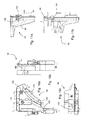
- Figs. 19a and 19b are detailed cross-sectional views through the reservoir inlet unit 70 in the mounted state, corresponding to Figs. 18b and c , respectively, wherein in Fig. 19a the filter valve 198 is open, while it is closed in Fig. 19b .
- the cross-sections of Fig. 19a and b are taken in a plane parallel to the front of the dryer through the center of unit 70, wherein the section plane is a vertical plane.
- the filter housing 130 and the filter 190 housed therein are shown in cross-section, wherein the filter extends in vertical direction and basically has rotational symmetry in a horizontal section plane.
- the filter 190 has a coarse filter grid 194 forming a cylindrical basket at the upper end.
- a fine filter mesh (not shown) is supported by the coarse filter grid 194, wherein the fine filter mesh is adapted to filter the fluff out of the condensate water passing the filter 190.
- the filter has a round passage or opening 196 which is arranged neighboring to the opening for the condensate coupling 106 which is protruding at the rear side of unit 70.
- the filter housing 130 has a section with a lower diameter over which the upper end of the riser pipe 82 is drawn.
- the inner of the riser pipe 82 communicates with passages 208 formed at the lower end of the filter 190 between a valve seat 206 and a valve head 200 of the filter valve 198.
- Fig. 19a shows the valve 198 in the open state such that the passages 208 are open (the filter switch 192 is in the left position when seen in Fig. 19a ).
- the passages 208 are closed as the valve seat 206 abuts against an O-ring 202 arranged at the valve head 200. In this position the filter switch 192 is at the right position (in the middle position within the filter access 134).
- valve head 200 has a collector recess 210 which is arranged lower than the valve head 200 such that fluff or other debris released from the inside of the fine filter collects there without blocking the valve seats.
- an O-ring 212 seals the cylindrical ring gap between the outside of the fine mesh (outer space 216) and filter grid 194 and the inside of filter housing 130 such that no unfiltered condensate water can pass the filter towards the reservoir 62 or towards the filter access region 134.
- a helix-shaped spring 204 is arranged between the outside of filter 190 and the inside of filter housing 130.
- the spring 204 is biased when the valve is open.
- filter switch 192 is shifted to the right side ( Fig. 19b )
- the compression force compressing spring 204 is released and the spring 204 lifts the lower section of the filter (the cylindrical pipe section below the filter grid 194) such that the valve 198 is closed.
- the top end of filter 190 above the filter grid 194 is formed by the filter cap 217 which provides a hinge and cam connection 218 to a cam 220 which is formed at the lower side of filter switch 192.
- the cam 220 has a cam curve 222 which interacts with pins arranged at the filter cap 217.
- a lower section of cam curve 222 acts on the pins of the filter cap 217 (not shown) and presses the filter 190 to its lowest position within filter housing 130 such that the valve 198 is open.
- the filter switch 192 is moved to its right position as shown in Fig. 19b , the pins at the filter 217 move upwards along the cam curve 222 due to the bias force of spring 204.
- filter switch 192 also serves as handle or grip for removing the upper filter part from or insert it into the filter housing 130.
- the user can manually fill reservoir 62 by supplying water or another liquid through the filling inlet 136. This gives the user the possibility to exclude condensate water from being supplied to the steam generation unit 140.
- the user may also fill in water with an additive or an additive liquid as such into the reservoir.
- the additive or additive liquid may be for example a treatment agent for dry cleaning, for waterproofing the laundry, for disinfecting the laundry, for softening the laundry or the like.
- Fig. 6 shows the cross-section through unit 70 along the section line A-A in Fig. 5 .
- the cross-section is taken through the center of filter 190 and filter housing 130.
- the cross-section is in a vertical plane perpendicular to the front of the dryer 2.
- the opening 196 of the filter grid 194 overlaps or coincides with the opening of the condensate plug 132.
- the other filter grid 194 also the opening 196 in the coarse filter grid 194 is covered by the fine mesh of the filter.
- Fig. 20a and 20b show top views to the front frame 30 and the filling area and filter access 134 of the reservoir inlet unit 70 as described above.
- the steam generator 140 is arranged at the upper side of the upper shell or upper cover of the battery channel 78.
- the generator 140 has a heater body 142 for heating the liquid supplied from reservoir 62, wherein the heater body 142 is of the continuous-flow heater type in this embodiment, which only heats small amounts of liquid in a pipe leading through the heater.
- the steam generator 140 may also be a boiler-type steam generator having a container with a heater inside or outside the container to heat up larger amounts of liquid therein.
- An inlet 144 of the heater is connected to a pump 148 which in turn is connected to the feed pipe 84 coming from reservoir 62.
- Pump 148 has dosing function in that it pumps an amount of liquid into the heater body 142 in a controlled way (closed loop control or open loop control provided by control unit 300) such as to guarantee that nearly droplet-free steam leaves the heater body 142.
- a controlled valve could also be provided to dose the liquid amount to be supplied to the heater 142.
- the heater body 142 has a steam outlet 146 where the steam generated in the heater body 142 exits towards the laundry storing compartment.
- the steam generator unit 140 uses an inline or flow-through heater in which the water is heated and evaporated to steam while the water is flowing through the heater.
- a boiler-type steam generator may be used in which an amount of water is supplied to a boiler container and is heated therein to generate the steam which is drained or exhausted from the liquid surface to the outlet of the boiler chamber.
- Figs. 12 and 13 further show at the rear end of the upper section or upper cover of the base or battery top cover 230 a wheel bearing 232 on which a wheel (not shown) is rotatably mounted at wheel axis 234. Only one of four wheel bearings with wheels is shown on which the cylindrically-shaped drum 20 is rotatably supported.
- the rotatable drum is open at the front and rear side, which are closed to form the laundry storing compartment by the compartment back wall 26 and the back side of the front frame and the loading door.
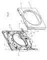
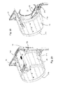
- FIGs. 29 and 30 show rear perspective views of the drum 20 and the front frame 30, wherein the front edge 21a and the rear edge 21b of the cylindrical drum wall are shown.
- a portion of the drum cylinder is cut out to have a cross-sectional view to a drum sealing 236 provided at the front side of the drum.
- the drum sealing 236 is shown in more detail in Fig. 31 which is similar to the cross section detail B of Fig. 30 .
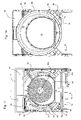
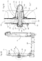
- Fig. 21 shows a detailed view of a steam inlet unit 250 with the cone 252 corresponding to an enlargement of the circle section A in Fig. 12 .
- Steam outlets 254 are provided at the free-standing end or the front section of cone 252 at the upper side thereof. It is to be noted that the outlets 254 do not supply processing air to the laundry storing compartment and that the rear wall openings 28 do not supply steam into the laundry storing compartment.
- the steam does not distribute in all the volume of the cone, but only in the separation chamber 264 from where it enters into the laundry treatment compartment formed by the drum and the front and rear walls thereof through the steam outlets 254.
- the steam outlets 254 are distant or offset to the walls defining the laundry storing compartment, the steam is introduced closer and more efficient to the inner or center of the storing compartment which results in a more efficient steam distribution in the compartment volume.
- Valve 198 may be integrated in unit 70 or directly in the reservoir 62 or it may be arranged at another position in the supply line from the condensate pump unit 92 to the reservoir 62.
- Valve may for example be a controllable valve, like a solenoid valve which is controlled (closed and opened) under the control of control unit 300.
Priority Applications (3)
| Application Number | Priority Date | Filing Date | Title |
|---|---|---|---|
| EP11195958.1A EP2610392A1 (fr) | 2011-12-28 | 2011-12-28 | Appareil domestique pour sécher le linge doté d'une unité de buse de vapeur |
| EP12199322.4A EP2610393A1 (fr) | 2011-12-28 | 2012-12-24 | Appareil domestique pour sécher le linge doté d'une unité de buse de vapeur |
| EP12199323.2A EP2610394B1 (fr) | 2011-12-28 | 2012-12-24 | Appareil domestique de séchage du linge doté d'une unité de buse à vapeur |
Applications Claiming Priority (1)
| Application Number | Priority Date | Filing Date | Title |
|---|---|---|---|
| EP11195958.1A EP2610392A1 (fr) | 2011-12-28 | 2011-12-28 | Appareil domestique pour sécher le linge doté d'une unité de buse de vapeur |
Publications (1)
| Publication Number | Publication Date |
|---|---|
| EP2610392A1 true EP2610392A1 (fr) | 2013-07-03 |
Family
ID=47358560
Family Applications (3)
| Application Number | Title | Priority Date | Filing Date |
|---|---|---|---|
| EP11195958.1A Withdrawn EP2610392A1 (fr) | 2011-12-28 | 2011-12-28 | Appareil domestique pour sécher le linge doté d'une unité de buse de vapeur |
| EP12199322.4A Withdrawn EP2610393A1 (fr) | 2011-12-28 | 2012-12-24 | Appareil domestique pour sécher le linge doté d'une unité de buse de vapeur |
| EP12199323.2A Active EP2610394B1 (fr) | 2011-12-28 | 2012-12-24 | Appareil domestique de séchage du linge doté d'une unité de buse à vapeur |
Family Applications After (2)
| Application Number | Title | Priority Date | Filing Date |
|---|---|---|---|
| EP12199322.4A Withdrawn EP2610393A1 (fr) | 2011-12-28 | 2012-12-24 | Appareil domestique pour sécher le linge doté d'une unité de buse de vapeur |
| EP12199323.2A Active EP2610394B1 (fr) | 2011-12-28 | 2012-12-24 | Appareil domestique de séchage du linge doté d'une unité de buse à vapeur |
Country Status (1)
| Country | Link |
|---|---|
| EP (3) | EP2610392A1 (fr) |
Cited By (1)
| Publication number | Priority date | Publication date | Assignee | Title |
|---|---|---|---|---|
| WO2020049122A1 (fr) * | 2018-09-06 | 2020-03-12 | Meiko Maschinenbau Gmbh & Co. Kg | Dispositif de nettoyage pour le nettoyage d'un produit à nettoyer et procédé de fabrication d'un dispositif de nettoyage |
Families Citing this family (3)
| Publication number | Priority date | Publication date | Assignee | Title |
|---|---|---|---|---|
| CN104342897B (zh) * | 2013-08-08 | 2016-11-23 | 苏州三星电子有限公司 | 一种干衣机蒸汽喷头的安装结构以及干衣机 |
| WO2015078512A1 (fr) * | 2013-11-29 | 2015-06-04 | Arcelik Anonim Sirketi | Appareil d'injection de vapeur destiné à être utilisé dans un sèche-linge vapeur et sèche-linge vapeur mettant en œuvre ledit appareil |
| US10299656B2 (en) | 2016-11-09 | 2019-05-28 | Electrolux Home Products, Inc. | Vent outlet for appliance having adjustable kickplate |
Citations (11)
| Publication number | Priority date | Publication date | Assignee | Title |
|---|---|---|---|---|
| US3242584A (en) * | 1963-04-29 | 1966-03-29 | Gen Motors Corp | Domestic clothes drying appliance |
| US3256720A (en) * | 1963-08-14 | 1966-06-21 | Ametek Inc | Laundry machine |
| US4207683A (en) | 1979-02-01 | 1980-06-17 | Horton Roberta J | Clothes dryer |
| DE4021533A1 (de) * | 1990-07-06 | 1992-01-09 | Bauknecht Hausgeraete | Trockner oder waschtrockner mit einer waeschetrommel |
| US20080000098A1 (en) * | 2006-02-20 | 2008-01-03 | Choi Chul J | Drying machine and method for controlling the same |
| WO2008038887A1 (fr) * | 2006-09-25 | 2008-04-03 | Lg Electronics Inc. | Sèche-linge |
| DE102006061210A1 (de) * | 2006-12-22 | 2008-06-26 | BSH Bosch und Siemens Hausgeräte GmbH | Trommel für ein Hausgerät zur Pflege von Wäschestücken |
| EP2042644A1 (fr) * | 2007-09-27 | 2009-04-01 | LG Electronics Inc. | Sèche-linge |
| US20100024243A1 (en) * | 2008-07-31 | 2010-02-04 | Electrolux Home Products | Laundry dryer providing moisture application during tumbling and reduced airflow |
| US20100115788A1 (en) * | 2005-11-10 | 2010-05-13 | Lg Electronics Inc. | Steam Generator and Laundry Dryer Having the Same and Controlling Method Thereof |
| US20100180465A1 (en) * | 2007-07-13 | 2010-07-22 | Electrolux Home Products Corporation N.V. | Method of determining clogging of the steam generator tank filter of a home laundry drier, and home laundry drier implementing such a method |
Family Cites Families (2)
| Publication number | Priority date | Publication date | Assignee | Title |
|---|---|---|---|---|
| DE10260151A1 (de) | 2002-12-20 | 2004-07-01 | BSH Bosch und Siemens Hausgeräte GmbH | Wäschetrockner und Verfahren zur Geruchsentfernung aus Textilien |
| PL1887127T3 (pl) | 2006-08-08 | 2017-03-31 | Electrolux Home Products Corporation N.V. | Maszyna do obróbki materiałów pranych |
-
2011
- 2011-12-28 EP EP11195958.1A patent/EP2610392A1/fr not_active Withdrawn
-
2012
- 2012-12-24 EP EP12199322.4A patent/EP2610393A1/fr not_active Withdrawn
- 2012-12-24 EP EP12199323.2A patent/EP2610394B1/fr active Active
Patent Citations (11)
| Publication number | Priority date | Publication date | Assignee | Title |
|---|---|---|---|---|
| US3242584A (en) * | 1963-04-29 | 1966-03-29 | Gen Motors Corp | Domestic clothes drying appliance |
| US3256720A (en) * | 1963-08-14 | 1966-06-21 | Ametek Inc | Laundry machine |
| US4207683A (en) | 1979-02-01 | 1980-06-17 | Horton Roberta J | Clothes dryer |
| DE4021533A1 (de) * | 1990-07-06 | 1992-01-09 | Bauknecht Hausgeraete | Trockner oder waschtrockner mit einer waeschetrommel |
| US20100115788A1 (en) * | 2005-11-10 | 2010-05-13 | Lg Electronics Inc. | Steam Generator and Laundry Dryer Having the Same and Controlling Method Thereof |
| US20080000098A1 (en) * | 2006-02-20 | 2008-01-03 | Choi Chul J | Drying machine and method for controlling the same |
| WO2008038887A1 (fr) * | 2006-09-25 | 2008-04-03 | Lg Electronics Inc. | Sèche-linge |
| DE102006061210A1 (de) * | 2006-12-22 | 2008-06-26 | BSH Bosch und Siemens Hausgeräte GmbH | Trommel für ein Hausgerät zur Pflege von Wäschestücken |
| US20100180465A1 (en) * | 2007-07-13 | 2010-07-22 | Electrolux Home Products Corporation N.V. | Method of determining clogging of the steam generator tank filter of a home laundry drier, and home laundry drier implementing such a method |
| EP2042644A1 (fr) * | 2007-09-27 | 2009-04-01 | LG Electronics Inc. | Sèche-linge |
| US20100024243A1 (en) * | 2008-07-31 | 2010-02-04 | Electrolux Home Products | Laundry dryer providing moisture application during tumbling and reduced airflow |
Cited By (3)
| Publication number | Priority date | Publication date | Assignee | Title |
|---|---|---|---|---|
| WO2020049122A1 (fr) * | 2018-09-06 | 2020-03-12 | Meiko Maschinenbau Gmbh & Co. Kg | Dispositif de nettoyage pour le nettoyage d'un produit à nettoyer et procédé de fabrication d'un dispositif de nettoyage |
| CN112638229A (zh) * | 2018-09-06 | 2021-04-09 | 迈科清洗科技集团公司 | 用于清洁待清洁物品的清洁装置和制造清洁装置的方法 |
| CN112638229B (zh) * | 2018-09-06 | 2024-04-30 | 迈科清洗科技集团公司 | 用于清洁待清洁物品的清洁装置和制造清洁装置的方法 |
Also Published As
| Publication number | Publication date |
|---|---|
| EP2610393A1 (fr) | 2013-07-03 |
| EP2610394B1 (fr) | 2015-04-15 |
| EP2610394A1 (fr) | 2013-07-03 |
Similar Documents
| Publication | Publication Date | Title |
|---|---|---|
| EP2610391B1 (fr) | Appareil domestique pour sécher le linge doté d'une unité de buse de vapeur | |
| EP2818593B1 (fr) | Appareil ménager pour le traitement du linge comportant un réservoir d'eau | |
| CN112714811B (zh) | 衣物护理装置 | |
| US7987616B2 (en) | Laundry machine | |
| EP2403985B1 (fr) | Module de pompe à chaleur et dispositif de traitement de linge l'utilisant | |
| RU2471026C2 (ru) | Машина для сухой чистки, использующая очищающую жидкость, с блоком комбинированного фильтра | |
| US20060075790A1 (en) | Washing machine and lint removing apparatus thereof | |
| US20090151193A1 (en) | Cloth treating apparatus | |
| EP2353487A2 (fr) | Lave-vaisselle | |
| JP4781287B2 (ja) | 電気洗濯機 | |
| EP2610392A1 (fr) | Appareil domestique pour sécher le linge doté d'une unité de buse de vapeur | |
| EP3237674B1 (fr) | Appareil de séchage du linge équipé d'une pompe de vidange de liquide | |
| US11260329B2 (en) | Laundry dryer | |
| EP2610399B1 (fr) | Appareil domestique pour sécher le linge doté d'un réservoir pour liquides | |
| KR20080070497A (ko) | 세탁기용 표시부 및 세탁기 | |
| EP2610395B1 (fr) | Réservoir pour liquides pour appareil domestique doté d'une unité d'indication du niveau de liquide | |
| EP2610396B1 (fr) | Appareil domestique pour sécher le linge doté d'un réservoir pour liquides | |
| EP2610397B1 (fr) | Appareil domestique pour sécher le linge doté d'un réservoir pour liquides avec une entrée de remplissage | |
| EP2610398B1 (fr) | Réservoir pour liquides pour appareil domestique doté d'un élément flottant du niveau de liquide | |
| EP2821540B1 (fr) | Appareil domestique de séchage du linge doté d'une unité de buse à vapeur | |
| EP3124683B1 (fr) | Seche-linge | |
| ES2614424T3 (es) | Máquina de tratamiento de la colada | |
| CN215887665U (zh) | 储水盒组件及具有其的干衣设备 | |
| CN218090206U (zh) | 衣物护理设备 | |
| KR101342364B1 (ko) | 스팀건조기 |
Legal Events
| Date | Code | Title | Description |
|---|---|---|---|
| PUAI | Public reference made under article 153(3) epc to a published international application that has entered the european phase |
Free format text: ORIGINAL CODE: 0009012 |
|
| AK | Designated contracting states |
Kind code of ref document: A1 Designated state(s): AL AT BE BG CH CY CZ DE DK EE ES FI FR GB GR HR HU IE IS IT LI LT LU LV MC MK MT NL NO PL PT RO RS SE SI SK SM TR |
|
| AX | Request for extension of the european patent |
Extension state: BA ME |
|
| STAA | Information on the status of an ep patent application or granted ep patent |
Free format text: STATUS: THE APPLICATION IS DEEMED TO BE WITHDRAWN |
|
| 18D | Application deemed to be withdrawn |
Effective date: 20140104 |