EP2610381A1 - Method and apparatus for generating knitting data for flat knitting machine - Google Patents
Method and apparatus for generating knitting data for flat knitting machine Download PDFInfo
- Publication number
- EP2610381A1 EP2610381A1 EP12007872.0A EP12007872A EP2610381A1 EP 2610381 A1 EP2610381 A1 EP 2610381A1 EP 12007872 A EP12007872 A EP 12007872A EP 2610381 A1 EP2610381 A1 EP 2610381A1
- Authority
- EP
- European Patent Office
- Prior art keywords
- carrier
- carriers
- knitting
- stop positions
- data
- Prior art date
- Legal status (The legal status is an assumption and is not a legal conclusion. Google has not performed a legal analysis and makes no representation as to the accuracy of the status listed.)
- Granted
Links
Images




Classifications
-
- D—TEXTILES; PAPER
- D04—BRAIDING; LACE-MAKING; KNITTING; TRIMMINGS; NON-WOVEN FABRICS
- D04B—KNITTING
- D04B7/00—Flat-bed knitting machines with independently-movable needles
- D04B7/24—Flat-bed knitting machines with independently-movable needles for producing patterned fabrics
- D04B7/26—Flat-bed knitting machines with independently-movable needles for producing patterned fabrics with colour patterns
-
- D—TEXTILES; PAPER
- D04—BRAIDING; LACE-MAKING; KNITTING; TRIMMINGS; NON-WOVEN FABRICS
- D04B—KNITTING
- D04B15/00—Details of, or auxiliary devices incorporated in, weft knitting machines, restricted to machines of this kind
- D04B15/94—Driving-gear not otherwise provided for
- D04B15/99—Driving-gear not otherwise provided for electrically controlled
-
- D—TEXTILES; PAPER
- D04—BRAIDING; LACE-MAKING; KNITTING; TRIMMINGS; NON-WOVEN FABRICS
- D04B—KNITTING
- D04B15/00—Details of, or auxiliary devices incorporated in, weft knitting machines, restricted to machines of this kind
- D04B15/30—Driving devices for thread-carrier rods
-
- D—TEXTILES; PAPER
- D04—BRAIDING; LACE-MAKING; KNITTING; TRIMMINGS; NON-WOVEN FABRICS
- D04B—KNITTING
- D04B15/00—Details of, or auxiliary devices incorporated in, weft knitting machines, restricted to machines of this kind
- D04B15/66—Devices for determining or controlling patterns ; Program-control arrangements
Definitions
- the present invention relates to generation of knitting data for a flat knitting machine, and particularly relates to determination of stop positions of carriers in knitting data while preventing interference between the carriers.
- a flat knitting machine includes, for example, a pair of elongated needle beds, wherein a knitted fabric is knitted by causing a carriage that travels back and forth on the needle beds to operate needles, and feeding a yarn from carriers to the needles.
- a plurality of carrier rails are arranged above the needle beds in parallel to the longitudinal direction of the needle beds.
- the carriers are also referred to as yarn feeders, each having a lower end as a yarn feeding port for feeding a yarn and an upper end supported by the carrier rail.
- the carriers are elastic such that they may be slightly bent in the front-and-rear direction of the flat knitting machine. The carriers are slidingly moved along the carrier rails when being conveyed by the carriage, and stopped when the conveyance is cancelled.
- the carriage includes not only cams for operating the needles but also other constituent elements such as stitch pressers, and these constituent elements are positioned above the gap between the needle beds. Accordingly, when a plurality of carriers are stopped at the same position, the yarn feeding ports are brought into contact with these other constituent elements such as stitch pressers. Thus, processing is performed such that carriers are not stopped at the same position, that is, carriers are stopped at positions on the outer side of the knitting width by parameters called reset correction.
- the reset correction values have to be manually input. Note that the reset correction values are part of the knitting data because they directly affect factors such as movement distance and operation of the carriers.
- Patent Literature 1 JP H5-93348A discloses correction of a position at which the conveyance of carriers is cancelled, in consideration of the slippage amount of the carriers.
- Patent Literature 2 JP 2011-106059A describes arrangement of carrier rails and carriers with respect to needle beds. However, automatic generation of data indicating a carrier stop position is not known.
- the present invention is directed to method for automatically generating knitting data for a flat knitting machine including at least a pair of front and rear needle beds, a carriage that operates needles on the needle beds, a plurality of carrier rails, and a plurality of carriers that are conveyed by the carriage along the respective carrier rails and feed at least a yarn to the needles on the needle beds, characterized by including:
- the present invention is directed to an apparatus for automatically generating knitting data for a flat knitting machine including at least a pair of front and rear needle beds, a carriage that operates needles on the needle beds, a plurality of carrier rails, and a plurality of carriers that are conveyed by the carriage along the respective carrier rails and feed at least a yarn to the needles on the needle beds, characterized by including:
- the stop positions of the carriers are automatically determined. Furthermore, the stop positions of the carriers are prevented from overlapping each other in a direction that is at a right angle to the longitudinal direction of the needle beds in a horizontal plane, and, thus, the carriers are prevented from interfering with each other.
- the stop positions of the carriers may be positions directly above the edge of the knitting width, as well as positions that is remote to the position directly above the edge of the knitting width obtained by the minimum value in FIG. 4 .
- the analysis means corresponds to, for example, the usage frequency extractor or the block extractor in FIG. 2
- the stop position determination means corresponds to, for example, the reset correction value allocation unit in FIG. 2 .
- the description regarding the knitting data generation method is applicable as it concerns the knitting data generation apparatus, and the description regarding the knitting data generation apparatus is applicable as it concerns the knitting data generation method.
- the stop position determination means determines the stop positions such that a carrier having a high usage frequency is stopped at a position close to an edge of a knitting width and a carrier having a low usage frequency is stopped at a position away from the edge of the knitting width.
- the usage frequency level may be obtained with an appropriate level of precision, and, for example, if the level of resolution is set to "three times", the numbers of times used of 51 and 49 are classified into the same usage frequency.
- the stop positions of carriers what matters are values of carriers having high usage frequencies, and the stop positions of carriers having, for example, the two lowest usage frequencies do not have to follow the order of usage frequency.
- the stop position determination means determines the stop positions based on the usage frequency in each part. With this configuration, the stop positions are easily determined. Furthermore, it is preferable that the analysis means divides one part into a plurality of blocks in a wale direction, and in that the stop position determination means determines the stop positions based on the usage frequency in each block. With this configuration, for example, when carriers that are to be used are changed along the wale direction, the stop positions are determined such that the total distance in which the carriers are conveyed is short.
- FIGS. 1 to 8 show an embodiment and its modified example.
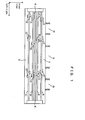
- FIG. 1 schematically shows carrier rails above needle beds, wherein reference numeral 2 denotes a front bed, 4 denotes a rear bed, and 6 denotes a gap between the beds.
- a plurality of carrier rails 8 to 11 are present above the beds 2 and 4, and carriers 12 are slidingly moved along the carrier rails 8 to 11 when being conveyed by a carriage (not shown).
- 14 reference numeral denotes a knitting width of a front body or the like
- 15 denotes a knitting width of a left sleeve or the like
- 16 denotes a knitting width of a right sleeve or the like.
- One garment is configured by a plurality of parts, and the knitting width of each part may be changed during knitting.
- a garment may have a fixed knitting width, and, furthermore, one garment may be configured by one part as in the case of non-sewing knitting.
- a direction that is parallel to the longitudinal direction of the beds 2 and 4 is referred to as a left-and-right direction, and a direction that is orthogonal to the longitudinal direction of the beds 2 and 4 is referred to as a front-and-rear direction.
- Reference numeral 20 denotes a knitting data generation apparatus
- 21 denotes a user interface that is configured by an input means such as a mouse, a track ball, a digitizer, and a keyboard, together with a color monitor
- 22 denotes a network interface that exchanges data and programs with a network.
- reference numeral 23 denotes a disc driver that exchanges data, programs, and the like with a disc (not shown)
- 24 denotes a memory that stores various type of data, in particular, knitting data
- 25 denotes a program memory that stores programs for the knitting data generation apparatus 20.
- a converter 26 converts knitted fabric design data input from the user interface 21, the network interface 22, the disc driver 23, or the like, to knitting data. In this conversion, data indicating stop positions of the carriers is not generated, or is allocated to an appropriate default value.
- a usage frequency extractor 27 extracts a usage frequency and a movement range in each course of each carrier used in knitting data.
- a block extractor 28 is used to execute the algorithm in FIG. 6 , and divides one part into a plurality of blocks based on which carrier to use. In the case where the algorithm in FIG. 3 is executed, the block extractor 28 is not necessary. One part is divided into blocks along the wale direction of the part, the block length along the wale direction is provided with a minimum value, and a block having a length less than the minimum value is merged into either its upper or lower block.
- a reset correction value allocation unit 29 allocates reset correction values to the carriers.
- the reset correction value may be fixed throughout knitting of one part, or may be changed during knitting of one part.
- An interference check unit 30 checks interference between the carriers, the interference being an event in which a plurality of carriers are stopped at positions that overlap each other in the front-and-rear direction of the flat knitting machine. When carriers interfere with each other, that is, when a plurality of carriers have been stopped in an overlapped manner in the front-and-rear direction, if the carriage (not shown) moves so as to cross the carriers, the stitch pressers and the like on the carriage may be damaged by interference with the carriers.
- the reset correction value allocation unit 29 initially allocates, for example, a reset correction value of 0 to each carrier. Then, when the interference check unit 30 detects that the carriers are to interfere with each other, the interference is eliminated, for example, by increasing a reset correction value for a carrier having a low usage frequency so as to avoid the interference.
- the knitting data generation apparatus 20 may be disposed inside a flat knitting machine, or may be disposed inside a design apparatus that generates design data of a garment or the like and converts it to knitting data.
- FIGS. 3 to 5 show a method for determining carrier stop positions.
- the knitting width, the stitch types, the number of courses, and which carrier is to be moved in which course over which range, and other types of data are determined.
- Step 1 for each carrier, courses using the carrier and a movement range in each course in one part are obtained.
- This processing is performed at least on carriers that are to be actually used.
- the usage frequency of the carriers in one part is determined for each carrier, and the stop position of each carrier is set to a minimum value. In other words, the reset correction value for each carrier is set at 0 (Step 2).
- Carriers that are not to be used are, for example, withdrawn to an end of the needle beds or the like.
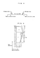
- FIG. 4 illustrates the reset correction values.
- the carriers are moved back and forth along the left and the right of the knitting width, and the carrier stop position is a position that is away from an edge of the knitting width by a distance of a minimum value corresponding to approximately zero to three needles.
- the minimum value is 0 in the case of intarsia knitting, and is a value corresponding to two or three needles in the case of other types of knitting.
- the carrier movement range in the knitting data is obtained by adding the knitting width and the minimum values.
- the reset correction value is 0 at a position shifted from an edge of the knitting width by the minimum value to the outer side, which corresponds to a minimum reset correction value.
- the reset correction value increases toward the outer side of the knitting width.
- the reset correction value is expressed by, for example, a width of one yarn feeding port.
- reset means cancellation of the conveyance of the carrier by the carriage
- correction value means the amount of shift from the minimum value.
- Steps 4 to 7 are performed on the carriers, for example, in descending order of the usage frequency (Steps 3 to 7).
- Step 4 the position of a carrier when it is stopped in each course is checked, and it is detected whether or not there is interference with any other carrier. If there is interference with any other carrier, the interference is eliminated by shifting the stop position to the outer sides, that is, by increasing the reset correction value (Step 5). If the stop positions of the carriers that are to cause interference are changed, interference with other carriers may occur as a chain reaction, and, thus, the stop positions of the carriers are changed until elimination of interference is completed.
- Steps 4 and 5 are performed on all the courses, for example, the same processing is performed on a carrier having the next highest usage frequency. The algorithm in FIG. 3 ends if the processing is completed for all the carriers that are to be used.
- FIG. 5 shows reset correction values (dashed dotted lines) and actual stop positions (dashed double dotted lines) of carriers a, b, and c during knitting of one part 32, wherein the reference symbols a, b, and c in the part 32 each indicate a carrier that is to be used.
- a course direction refers to a direction that is parallel to a direction in which a carriage travels back and forth
- a wale direction is a direction that is at a right angle to the course direction.
- the usage frequency of the carriers is in order of c > a > b, so that a smallest reset correction value is allocated to the carrier c, a second smallest reset correction value is allocated to the carrier a, and a largest reset correction value is allocated to the carrier b. If the knitting width of the part 32 does not increase or decrease, there is no interference between the carriers when the reset correction values are determined as above.
- the dashed dotted lines in FIG. 5 indicate the carrier stop positions following the reset correction values.
- the carrier stop positions may be the same even when the reset correction values are different from each other.
- the knitting width increases to the right side, but the carriers a and b are not used and are kept stationary in this block, and, thus, the carrier c interferes with the carriers a and b.
- the stop positions of the carriers a and b are automatically changed in Step 5 in FIG. 3 to positions as indicated by the dashed double dotted lines in FIG. 5 , or manually changed.
- the knitting width gradually decreases, and the carrier a interferes with the carrier c, and, thus, the stop position of the carrier c is changed, for example, to a position as indicated by the dashed double dotted line in FIG. 5 .
- FIG. 5 shows a case in which the carrier stop positions are shifted from the trajectories indicated by the dashed dotted lines to the trajectories indicated by the dashed double dotted lines in one pass of the carriage, the carrier stop positions may be gradually shifted between courses to avoid interference. Furthermore, it is sufficient that the carrier stop positions are shifted before a course where interference occurs.
- the reset correction values are variables that are allowed to change during knitting of one part, the reset correction values may be determined such that the trajectories are as indicated by the dashed double dotted lines on the right side in FIG. 5 .
- FIGS. 6 to 8 show a modified example that is the same as the embodiment in FIGS. 1 to 5 unless otherwise specified.
- Step 1 in FIG. 3 is performed, and the procedure advances to Step 11 where one part is divided into a plurality of blocks along the wale direction based on which carrier to use. At that time, it is preferable that a small block having a number of courses of a predetermined value or less is prevented from being formed, by setting a minimum value for the block length along the wale direction, for example.
- the usage frequency of the carriers is obtained for each block.
- the following process is performed in each block, and, in Step 12, the stop position of each carrier is set to a minimum value. Then, interference in the block is eliminated, for example, as in Steps 4 to 7 in FIG. 3 (Step 13).
- FIG. 7 shows reset correction values for one part 33 as dashed dotted lines, wherein X marks indicate switching of the reset correction values.
- the small block shown at the lowermost position using the carrier a and the following small block using the carriers a and b are merged into one block, and, thus, for example, four blocks are formed in total. Then, the reset correction values are switched for the unit of each block.
- the carrier a is mainly used, and the carrier b is also used, so that the reset correction value for the carrier a is set at 0, which is the minimum value, the reset correction value for the carrier b is set at 1, and the reset correction value for the carrier c is set at 2.
- the carrier a is not used, so that, for example, the reset correction values are switched between the carriers a and b.
- the carrier b is not used, so that the reset correction values are switched between the carriers b and c.
- the carrier c is not used, so that the reset correction values are switched between the carriers c and a.
- interference occurs, for example, between the carrier a whose stop position is fixed because it is not used, and the carriers b and c whose stop positions are shifted to the right side as the knitting width increases.
- interference is avoided by shifting the stop positions of the carriers that are to cause interference to a side away from the knitting width.
- FIG. 8 shows reset correction values in intarsia knitting according to the modified example, wherein carriers for intarsia knitting are allowed to be stopped at positions directly above an edge of the knitting width and directly above a yarn change point such that a yarn is oriented downward in the vertical direction.
- the area knitted by one carrier is taken as one knitting width, and one part 34 is processed as having two knitting widths in the course direction. Since the minimum value is 0, the stop positions with a reset correction value of 0 match the boundaries between both edges of the part 34 and the areas.
- the part 34 is divided into two upper and lower blocks. In the first block, the carriers a and b are used, so that small reset correction values are allocated to the carriers a and b.
- the carriers c and d are used, so that small reset correction values are allocated to the carriers c and d. If the fact that the block using the carriers a and b is larger than the block using the carriers c and d is focused, and the reset correction values for the lower block are taken as being effective also for the upper block, this processing is the same as that in the embodiment in FIGS. 1 to 5 .
Landscapes
- Engineering & Computer Science (AREA)
- Textile Engineering (AREA)
- Knitting Machines (AREA)
- Braiding, Manufacturing Of Bobbin-Net Or Lace, And Manufacturing Of Nets By Knotting (AREA)
Abstract
Description
- The present invention relates to generation of knitting data for a flat knitting machine, and particularly relates to determination of stop positions of carriers in knitting data while preventing interference between the carriers.
- A flat knitting machine includes, for example, a pair of elongated needle beds, wherein a knitted fabric is knitted by causing a carriage that travels back and forth on the needle beds to operate needles, and feeding a yarn from carriers to the needles. A plurality of carrier rails are arranged above the needle beds in parallel to the longitudinal direction of the needle beds. The carriers are also referred to as yarn feeders, each having a lower end as a yarn feeding port for feeding a yarn and an upper end supported by the carrier rail. The carriers are elastic such that they may be slightly bent in the front-and-rear direction of the flat knitting machine. The carriers are slidingly moved along the carrier rails when being conveyed by the carriage, and stopped when the conveyance is cancelled.
- Since the yarn feeding ports of the carriers move directly above a gap between the needle beds, when the carriers pass each other, the yarn feeding ports are brought into contact with each other. At that time, the carriers are slightly bent such that the yarn feeding ports are allowed to pass each other. The carriage includes not only cams for operating the needles but also other constituent elements such as stitch pressers, and these constituent elements are positioned above the gap between the needle beds. Accordingly, when a plurality of carriers are stopped at the same position, the yarn feeding ports are brought into contact with these other constituent elements such as stitch pressers. Thus, processing is performed such that carriers are not stopped at the same position, that is, carriers are stopped at positions on the outer side of the knitting width by parameters called reset correction. It is possible to prevent a plurality of carriers from being stopped at the same position, by providing different reset correction values for the respective carriers. However, for this purpose, the reset correction values have to be manually input. Note that the reset correction values are part of the knitting data because they directly affect factors such as movement distance and operation of the carriers.
- Patent Literature 1 (
JP H5-93348A JP 2011-106059A -
- [Patent Literature 1]
JP H5-93348A - [Patent Literature 2]
JP 2011-106059A - It is an object of the present invention to automatically generate knitting data including data indicating stop positions of carriers while preventing the carriers from interfering with each other.
- The present invention is directed to method for automatically generating knitting data for a flat knitting machine including at least a pair of front and rear needle beds, a carriage that operates needles on the needle beds, a plurality of carrier rails, and a plurality of carriers that are conveyed by the carriage along the respective carrier rails and feed at least a yarn to the needles on the needle beds, characterized by including:
- a step of obtaining, for each carrier used for knitting, data indicating at least a course of the carriage using the carrier and a movement range of the carrier in one part of a garment;
- a step of determining, for each carrier, a stop position of the carrier based on the data; and
- a step of, when it is detected that the stop positions of the carriers are to overlap each other in a direction that is at a right angle to a longitudinal direction of the needle beds in a horizontal plane, changing the stop positions such that the stop positions do not overlap each other.
- Furthermore, the present invention is directed to an apparatus for automatically generating knitting data for a flat knitting machine including at least a pair of front and rear needle beds, a carriage that operates needles on the needle beds, a plurality of carrier rails, and a plurality of carriers that are conveyed by the carriage along the respective carrier rails and feed at least a yarn to the needles on the needle beds, characterized by including:
- an analysis means for obtaining, for each carrier used for knitting, data indicating at least a course of the carriage using the carrier and a movement range of the carrier in one part of a garment; and
- a stop position determination means for determining, for each carrier, a stop position of the carrier based on the data, and, when it is detected that the stop positions of the carriers are to overlap each other in a direction that is at a right angle to a longitudinal direction of the needle beds in a horizontal plane, changing the stop positions such that the stop positions do not overlap each other.
- With this configuration, based on data indicating the usage frequency and the movement ranges of the carriers, the stop positions of the carriers are automatically determined. Furthermore, the stop positions of the carriers are prevented from overlapping each other in a direction that is at a right angle to the longitudinal direction of the needle beds in a horizontal plane, and, thus, the carriers are prevented from interfering with each other. The stop positions of the carriers may be positions directly above the edge of the knitting width, as well as positions that is remote to the position directly above the edge of the knitting width obtained by the minimum value in
FIG. 4 . The analysis means corresponds to, for example, the usage frequency extractor or the block extractor inFIG. 2 , and the stop position determination means corresponds to, for example, the reset correction value allocation unit inFIG. 2 . In this specification, the description regarding the knitting data generation method is applicable as it concerns the knitting data generation apparatus, and the description regarding the knitting data generation apparatus is applicable as it concerns the knitting data generation method. - It is preferable that the stop position determination means determines the stop positions such that a carrier having a high usage frequency is stopped at a position close to an edge of a knitting width and a carrier having a low usage frequency is stopped at a position away from the edge of the knitting width. With this configuration, since carriers having a high usage frequency are stopped at positions close to the edge of the knitting width, the distance in which the carriage moves the carriers is short. Accordingly, one part is knitted in a shorter period of time. Note that the usage frequency level may be obtained with an appropriate level of precision, and, for example, if the level of resolution is set to "three times", the numbers of times used of 51 and 49 are classified into the same usage frequency. Regarding the stop positions of carriers, what matters are values of carriers having high usage frequencies, and the stop positions of carriers having, for example, the two lowest usage frequencies do not have to follow the order of usage frequency.
- It is preferable that the stop position determination means determines the stop positions based on the usage frequency in each part. With this configuration, the stop positions are easily determined.
Furthermore, it is preferable that the analysis means divides one part into a plurality of blocks in a wale direction, and in that the stop position determination means determines the stop positions based on the usage frequency in each block. With this configuration, for example, when carriers that are to be used are changed along the wale direction, the stop positions are determined such that the total distance in which the carriers are conveyed is short. -
-
FIG. 1 is a plan view of needle beds and carrier rails. -
FIG. 2 is a block diagram of a knitting data generation apparatus according to an embodiment. -
FIG. 3 is a flowchart showing an algorithm for determining a carrier stop value according to the embodiment. -
FIG. 4 is a diagram showing a relationship between the knitting width of one part, the minimum value, and the reset correction value. -
FIG. 5 is a diagram schematically showing the stop positions of carriers a, b, and c with respect to one part. -
FIG. 6 is a flowchart showing an algorithm for determining a carrier stop value according to a modified example. -
FIG. 7 is a diagram schematically showing the stop positions of the carriers a, b, and c with respect to one part according to the modified example. -
FIG. 8 is a diagram schematically showing the stop positions of carriers a to d with respect to one part in intarsia knitting according to the modified example. - Hereinafter, an optimal embodiment for carrying out the present invention will be described.
-
FIGS. 1 to 8 show an embodiment and its modified example.FIG. 1 schematically shows carrier rails above needle beds, whereinreference numeral 2 denotes a front bed, 4 denotes a rear bed, and 6 denotes a gap between the beds. A plurality ofcarrier rails 8 to 11 are present above thebeds carriers 12 are slidingly moved along thecarrier rails 8 to 11 when being conveyed by a carriage (not shown). In this drawing, it is assumed that shaped knitting is performed, wherein 14 reference numeral denotes a knitting width of a front body or the like, 15 denotes a knitting width of a left sleeve or the like, and 16 denotes a knitting width of a right sleeve or the like. One garment is configured by a plurality of parts, and the knitting width of each part may be changed during knitting. A garment may have a fixed knitting width, and, furthermore, one garment may be configured by one part as in the case of non-sewing knitting. In this specification below, in a horizontal plane, a direction that is parallel to the longitudinal direction of thebeds beds -
Reference numeral 20 denotes a knitting data generation apparatus, 21 denotes a user interface that is configured by an input means such as a mouse, a track ball, a digitizer, and a keyboard, together with a color monitor, and 22 denotes a network interface that exchanges data and programs with a network. Furthermore, reference numeral 23 denotes a disc driver that exchanges data, programs, and the like with a disc (not shown), 24 denotes a memory that stores various type of data, in particular, knitting data, and 25 denotes a program memory that stores programs for the knittingdata generation apparatus 20. - A
converter 26 converts knitted fabric design data input from theuser interface 21, thenetwork interface 22, the disc driver 23, or the like, to knitting data. In this conversion, data indicating stop positions of the carriers is not generated, or is allocated to an appropriate default value. Ausage frequency extractor 27 extracts a usage frequency and a movement range in each course of each carrier used in knitting data. Ablock extractor 28 is used to execute the algorithm inFIG. 6 , and divides one part into a plurality of blocks based on which carrier to use. In the case where the algorithm inFIG. 3 is executed, theblock extractor 28 is not necessary. One part is divided into blocks along the wale direction of the part, the block length along the wale direction is provided with a minimum value, and a block having a length less than the minimum value is merged into either its upper or lower block. - A reset correction
value allocation unit 29 allocates reset correction values to the carriers. The reset correction value may be fixed throughout knitting of one part, or may be changed during knitting of one part. Aninterference check unit 30 checks interference between the carriers, the interference being an event in which a plurality of carriers are stopped at positions that overlap each other in the front-and-rear direction of the flat knitting machine. When carriers interfere with each other, that is, when a plurality of carriers have been stopped in an overlapped manner in the front-and-rear direction, if the carriage (not shown) moves so as to cross the carriers, the stitch pressers and the like on the carriage may be damaged by interference with the carriers. - The reset correction
value allocation unit 29 initially allocates, for example, a reset correction value of 0 to each carrier. Then, when theinterference check unit 30 detects that the carriers are to interfere with each other, the interference is eliminated, for example, by increasing a reset correction value for a carrier having a low usage frequency so as to avoid the interference. Note that the knittingdata generation apparatus 20 may be disposed inside a flat knitting machine, or may be disposed inside a design apparatus that generates design data of a garment or the like and converts it to knitting data. -
FIGS. 3 to 5 show a method for determining carrier stop positions. When a design of one part is determined and then converted to knitting data, the knitting width, the stitch types, the number of courses, and which carrier is to be moved in which course over which range, and other types of data are determined. Thus, inStep 1, for each carrier, courses using the carrier and a movement range in each course in one part are obtained. This processing is performed at least on carriers that are to be actually used. The usage frequency of the carriers in one part is determined for each carrier, and the stop position of each carrier is set to a minimum value. In other words, the reset correction value for each carrier is set at 0 (Step 2). Carriers that are not to be used are, for example, withdrawn to an end of the needle beds or the like. -
FIG. 4 illustrates the reset correction values. The carriers are moved back and forth along the left and the right of the knitting width, and the carrier stop position is a position that is away from an edge of the knitting width by a distance of a minimum value corresponding to approximately zero to three needles. For example, the minimum value is 0 in the case of intarsia knitting, and is a value corresponding to two or three needles in the case of other types of knitting. The carrier movement range in the knitting data is obtained by adding the knitting width and the minimum values. The reset correction value is 0 at a position shifted from an edge of the knitting width by the minimum value to the outer side, which corresponds to a minimum reset correction value. The reset correction value increases toward the outer side of the knitting width. Furthermore, the reset correction value is expressed by, for example, a width of one yarn feeding port. In the reset correction value, "reset" means cancellation of the conveyance of the carrier by the carriage, and "correction value" means the amount of shift from the minimum value. When the reset correction value is minimum, the carrier is stopped at a position shifted from an edge of the knitting width by the minimum value to the outer side, and, as the reset correction value increases, the carrier is stopped at a position shifted further away from the edge of the knitting width to the outer side. -
Steps 4 to 7 are performed on the carriers, for example, in descending order of the usage frequency (Steps 3 to 7). InStep 4, the position of a carrier when it is stopped in each course is checked, and it is detected whether or not there is interference with any other carrier. If there is interference with any other carrier, the interference is eliminated by shifting the stop position to the outer sides, that is, by increasing the reset correction value (Step 5). If the stop positions of the carriers that are to cause interference are changed, interference with other carriers may occur as a chain reaction, and, thus, the stop positions of the carriers are changed until elimination of interference is completed. AfterSteps FIG. 3 ends if the processing is completed for all the carriers that are to be used. -
FIG. 5 shows reset correction values (dashed dotted lines) and actual stop positions (dashed double dotted lines) of carriers a, b, and c during knitting of onepart 32, wherein the reference symbols a, b, and c in thepart 32 each indicate a carrier that is to be used. Furthermore, in this specification, a course direction refers to a direction that is parallel to a direction in which a carriage travels back and forth, and a wale direction is a direction that is at a right angle to the course direction. In thepart 32, the usage frequency of the carriers is in order of c > a > b, so that a smallest reset correction value is allocated to the carrier c, a second smallest reset correction value is allocated to the carrier a, and a largest reset correction value is allocated to the carrier b. If the knitting width of thepart 32 does not increase or decrease, there is no interference between the carriers when the reset correction values are determined as above. The dashed dotted lines inFIG. 5 indicate the carrier stop positions following the reset correction values. - If the knitting width of the
part 32 increases or decreases, the carrier stop positions may be the same even when the reset correction values are different from each other. For example, in the block using the carrier c, the knitting width increases to the right side, but the carriers a and b are not used and are kept stationary in this block, and, thus, the carrier c interferes with the carriers a and b. Thus, the stop positions of the carriers a and b are automatically changed inStep 5 inFIG. 3 to positions as indicated by the dashed double dotted lines inFIG. 5 , or manually changed. In the last block using the carrier a, the knitting width gradually decreases, and the carrier a interferes with the carrier c, and, thus, the stop position of the carrier c is changed, for example, to a position as indicated by the dashed double dotted line inFIG. 5 . Note that, althoughFIG. 5 shows a case in which the carrier stop positions are shifted from the trajectories indicated by the dashed dotted lines to the trajectories indicated by the dashed double dotted lines in one pass of the carriage, the carrier stop positions may be gradually shifted between courses to avoid interference. Furthermore, it is sufficient that the carrier stop positions are shifted before a course where interference occurs. When it is assumed that the reset correction values are variables that are allowed to change during knitting of one part, the reset correction values may be determined such that the trajectories are as indicated by the dashed double dotted lines on the right side inFIG. 5 . - According to the above-described processing, it is possible to:
- automatically generate data indicating the stop positions of the carriers a, b, and c;
- shorten the carrier conveyance distance, thereby shortening the carriage travelling distance, and improving the productivity; and
- eliminate interference between the carriers.
-
FIGS. 6 to 8 show a modified example that is the same as the embodiment inFIGS. 1 to 5 unless otherwise specified. First,Step 1 inFIG. 3 is performed, and the procedure advances to Step 11 where one part is divided into a plurality of blocks along the wale direction based on which carrier to use. At that time, it is preferable that a small block having a number of courses of a predetermined value or less is prevented from being formed, by setting a minimum value for the block length along the wale direction, for example. Furthermore, inStep 11, the usage frequency of the carriers is obtained for each block. The following process is performed in each block, and, inStep 12, the stop position of each carrier is set to a minimum value. Then, interference in the block is eliminated, for example, as inSteps 4 to 7 inFIG. 3 (Step 13). -
FIG. 7 shows reset correction values for onepart 33 as dashed dotted lines, wherein X marks indicate switching of the reset correction values. In thepart 33, the small block shown at the lowermost position using the carrier a and the following small block using the carriers a and b are merged into one block, and, thus, for example, four blocks are formed in total. Then, the reset correction values are switched for the unit of each block. In the first block, the carrier a is mainly used, and the carrier b is also used, so that the reset correction value for the carrier a is set at 0, which is the minimum value, the reset correction value for the carrier b is set at 1, and the reset correction value for the carrier c is set at 2. In the next block using the carrier b, the carrier a is not used, so that, for example, the reset correction values are switched between the carriers a and b. In a similar manner, in the next block using the carrier c, the carrier b is not used, so that the reset correction values are switched between the carriers b and c. In the last block using the carrier a, the carrier c is not used, so that the reset correction values are switched between the carriers c and a. Furthermore, in the block using the carrier b and the block using the carrier c, interference occurs, for example, between the carrier a whose stop position is fixed because it is not used, and the carriers b and c whose stop positions are shifted to the right side as the knitting width increases. Thus, as inFIG. 5 , interference is avoided by shifting the stop positions of the carriers that are to cause interference to a side away from the knitting width. -
FIG. 8 shows reset correction values in intarsia knitting according to the modified example, wherein carriers for intarsia knitting are allowed to be stopped at positions directly above an edge of the knitting width and directly above a yarn change point such that a yarn is oriented downward in the vertical direction. In this case, the area knitted by one carrier is taken as one knitting width, and onepart 34 is processed as having two knitting widths in the course direction. Since the minimum value is 0, the stop positions with a reset correction value of 0 match the boundaries between both edges of thepart 34 and the areas. Thepart 34 is divided into two upper and lower blocks. In the first block, the carriers a and b are used, so that small reset correction values are allocated to the carriers a and b. In the next block, the carriers c and d are used, so that small reset correction values are allocated to the carriers c and d. If the fact that the block using the carriers a and b is larger than the block using the carriers c and d is focused, and the reset correction values for the lower block are taken as being effective also for the upper block, this processing is the same as that in the embodiment inFIGS. 1 to 5 . - According to the embodiment, the following effects are obtained, that is, it is possible to:
- (1) automatically generate data indicating the stop positions of the carriers;
- (2) eliminate interference between the carriers; and
- (3) determine the reset correction value according to the carrier usage frequency, thereby shortening the carriage travelling distance, and reducing the time necessary to perform knitting.
-
- 2
- Front bed
- 4
- Rear bed
- 6
- Gap
- 8 to 11
- Carrier rails
- 12
- Carrier
- 14 to 16
- Knitting width
- 20
- Knitting data generation apparatus
- 21
- User interface
- 22
- Network interface
- 23
- Disc driver
- 24
- Memory
- 25
- Program memory
- 26
- Converter
- 27
- Usage frequency extractor
- 28
- Block extractor
- 29
- Reset correction value allocation unit
- 30
- Interference check unit
- 32 to 34
- Part
Claims (5)
- A method for automatically generating knitting data for a flat knitting machine including at least a pair of front and rear needle beds (2, 4), a carriage that operates needles on the needle beds (2, 4), a plurality of carrier rails (8-11), and a plurality of carriers (12) that are conveyed by the carriage along the respective carrier rails (8-11) and feed at least a yarn to the needles on the needle beds (2, 4), characterized by:a step of obtaining, for each carrier (12) used for knitting, data indicating at least a course of the carriage using the carrier (12) and a movement range of the carrier (12) in one part (32-34) of a garment;a step of determining, for each carrier (12), a stop position of the carrier (12) based on the data; anda step of, when it is detected that the stop positions of the carriers (12) are to overlap each other in a direction that is at a right angle to a longitudinal direction of the needle beds (2, 4) in a horizontal plane, changing the stop positions such that the stop positions do not overlap each other.
- An apparatus (20) for automatically generating knitting data for a flat knitting machine including at least a pair of front and rear needle beds (2, 4), a carriage that operates needles on the needle beds (2, 4), a plurality of carrier rails (8-11), and a plurality of carriers (12) that are conveyed by the carriage along the respective carrier rails (8-11) and feed at least a yarn to the needles on the needle beds (2, 4), characterized by:an analysis means (27, 28) for obtaining, for each carrier (12) used for knitting, data indicating at least a course of the carriage using the carrier (12) and a movement range of the carrier (12) in one part (32-34) of a garment; anda stop position determination means (29) for determining, for each carrier (12), a stop position of the carrier (12) based on the data, and, when it is detected that the stop positions of the carriers (12) are to overlap each other in a direction that is at a right angle to a longitudinal direction of the needle beds (2, 4) in a horizontal plane, changing the stop positions such that the stop positions do not overlap each other.
- The apparatus (20) for generating knitting data for a flat knitting machine according to claim 2, characterized in that the stop position determination means (29) determines the stop positions such that a carrier (12) having a high usage frequency is stopped at a position close to an edge of a knitting width (14-16) and a carrier (12) having a low usage frequency is stopped at a position away from the edge of the knitting width (14-16).
- The apparatus (20) for generating knitting data for a flat knitting machine according to claim 3, characterized in that the stop position determination means (29) determines the stop positions based on the usage frequency in each part (32-34).
- The apparatus (20) for generating knitting data for a flat knitting machine according to claim 3, characterized in that the analysis means (28) divides one part (32-34) into a plurality of blocks in a wale direction, and in that the stop position determination means (29) determines the stop positions based on the usage frequency in each block.
Applications Claiming Priority (1)
| Application Number | Priority Date | Filing Date | Title |
|---|---|---|---|
| JP2011286041A JP5881412B2 (en) | 2011-12-27 | 2011-12-27 | Method and apparatus for generating knitting data for flat knitting machines |
Publications (2)
| Publication Number | Publication Date |
|---|---|
| EP2610381A1 true EP2610381A1 (en) | 2013-07-03 |
| EP2610381B1 EP2610381B1 (en) | 2017-05-17 |
Family
ID=47227423
Family Applications (1)
| Application Number | Title | Priority Date | Filing Date |
|---|---|---|---|
| EP12007872.0A Not-in-force EP2610381B1 (en) | 2011-12-27 | 2012-11-22 | Method and apparatus for generating knitting data for flat knitting machine |
Country Status (4)
| Country | Link |
|---|---|
| EP (1) | EP2610381B1 (en) |
| JP (1) | JP5881412B2 (en) |
| KR (1) | KR101377446B1 (en) |
| CN (1) | CN103184653B (en) |
Families Citing this family (3)
| Publication number | Priority date | Publication date | Assignee | Title |
|---|---|---|---|---|
| CN105648647B (en) * | 2015-12-31 | 2017-10-10 | 福建睿能科技股份有限公司 | Straight-bar machines and its machine head positioning method |
| KR102071933B1 (en) * | 2019-09-17 | 2020-01-31 | 이지수 | Knitting machine to stably produce fabric by adjusting the width of the body |
| CN110453364A (en) * | 2019-09-23 | 2019-11-15 | 江苏金龙科技股份有限公司 | A sky bar structure of self-running yarn feeder |
Citations (3)
| Publication number | Priority date | Publication date | Assignee | Title |
|---|---|---|---|---|
| DE2730306A1 (en) * | 1977-07-05 | 1979-01-25 | H Stoll Gmbh & Co Fa | Knitted goods with intarsia regions - are knitted on flat knitting machine with yarn guide for each region with even and odd regions being knitted with separate cams |
| JPH0593348A (en) | 1991-09-30 | 1993-04-16 | Shima Seiki Mfg Ltd | Apparatus for controlling stop position of yarn feeder |
| JP2011106059A (en) | 2009-11-18 | 2011-06-02 | Shima Seiki Mfg Ltd | Flat knitting machine |
Family Cites Families (7)
| Publication number | Priority date | Publication date | Assignee | Title |
|---|---|---|---|---|
| JPS5685449A (en) * | 1979-12-10 | 1981-07-11 | Shima Idea Center | Yarn guide lever moving control apparatus in traverse knitting machine |
| JPH0931807A (en) * | 1995-07-17 | 1997-02-04 | Tsudakoma Corp | Knitting of plaiting knit fabric |
| JP4125212B2 (en) * | 2003-10-10 | 2008-07-30 | 株式会社島精機製作所 | Flat knitting machine provided with removable knitting moving body and knitting member switching device |
| JP2006265794A (en) | 2005-03-25 | 2006-10-05 | Shima Seiki Mfg Ltd | Method for knitting knitted fabric containing tuck course by flat knitting machine and its program and design apparatus |
| EP1724385B1 (en) * | 2005-05-21 | 2016-05-18 | H. Stoll AG & Co. KG | Method of making knit fabric on a flat knitting machine |
| WO2009034910A1 (en) * | 2007-09-10 | 2009-03-19 | Shima Seiki Manufacturing, Ltd. | Device and method for debugging knit design and debug program |
| DE102009032627B4 (en) * | 2009-07-10 | 2012-10-18 | H. Stoll Gmbh & Co. Kg | Flat knitting machine with coupled with a drive means yarn guides |
-
2011
- 2011-12-27 JP JP2011286041A patent/JP5881412B2/en not_active Expired - Fee Related
-
2012
- 2012-11-08 KR KR1020120125902A patent/KR101377446B1/en not_active Expired - Fee Related
- 2012-11-22 EP EP12007872.0A patent/EP2610381B1/en not_active Not-in-force
- 2012-12-27 CN CN201210580973.8A patent/CN103184653B/en not_active Expired - Fee Related
Patent Citations (3)
| Publication number | Priority date | Publication date | Assignee | Title |
|---|---|---|---|---|
| DE2730306A1 (en) * | 1977-07-05 | 1979-01-25 | H Stoll Gmbh & Co Fa | Knitted goods with intarsia regions - are knitted on flat knitting machine with yarn guide for each region with even and odd regions being knitted with separate cams |
| JPH0593348A (en) | 1991-09-30 | 1993-04-16 | Shima Seiki Mfg Ltd | Apparatus for controlling stop position of yarn feeder |
| JP2011106059A (en) | 2009-11-18 | 2011-06-02 | Shima Seiki Mfg Ltd | Flat knitting machine |
Also Published As
| Publication number | Publication date |
|---|---|
| JP2013133577A (en) | 2013-07-08 |
| EP2610381B1 (en) | 2017-05-17 |
| KR20130075650A (en) | 2013-07-05 |
| KR101377446B1 (en) | 2014-03-25 |
| CN103184653B (en) | 2014-08-20 |
| JP5881412B2 (en) | 2016-03-09 |
| CN103184653A (en) | 2013-07-03 |
Similar Documents
| Publication | Publication Date | Title |
|---|---|---|
| WO2016115231A3 (en) | Method of simultaneously knitting opposing sides of an article of footwear | |
| EP2610381B1 (en) | Method and apparatus for generating knitting data for flat knitting machine | |
| EP2390393A1 (en) | Method for preventing ravel of knitting yarn and knitted fabric | |
| EP2568066B1 (en) | Set-up method of knitted fabric | |
| EP2280104A1 (en) | Device and program for loop length routine setting in a flatbed knitting machine | |
| EP1717362B1 (en) | Knitting method, knitting fabric and knit designing device for intersia pattern | |
| EP2942428B1 (en) | Method for split-knitting | |
| EP2492382B1 (en) | Knit design apparatus | |
| EP2775020A1 (en) | Flat knitting machine and knitting method using flat knitting machine | |
| EP2568068B1 (en) | Knitting method by flat knitting machine and editing apparatus for knitting data | |
| EP1900862B1 (en) | Knit simulation device, knit simulation method, and program therefor | |
| EP2292819B1 (en) | Design device and design method for knitted fabric using intarsia jacquard | |
| EP2636778B1 (en) | Method for preventing unraveling of knitting yarn | |
| EP2354284A1 (en) | Plating knitting method | |
| KR20240012419A (en) | Sinkers, knitting devices and knitting methods for producing knitted fabrics | |
| KR101569014B1 (en) | Method for knitting knitted fabric | |
| JP2020133009A (en) | Flat-knitting machine structure capable of changing needle bed gap size | |
| US10934642B2 (en) | Loop-forming method and device | |
| EP4101962A1 (en) | Knitted fabric knitting method, knit designing system, and storage medium | |
| EP2281933B1 (en) | Method for knitting knitted fabric with overlapped stitches, and knitted fabric | |
| US2820354A (en) | Circular knitting machines of the superimposed needle cylinder type | |
| GB2097825A (en) | Cam arrangement for knitting machines | |
| KR20080002500U (en) | Sinker Bed for Socks Knitting Machine |
Legal Events
| Date | Code | Title | Description |
|---|---|---|---|
| PUAI | Public reference made under article 153(3) epc to a published international application that has entered the european phase |
Free format text: ORIGINAL CODE: 0009012 |
|
| AK | Designated contracting states |
Kind code of ref document: A1 Designated state(s): AL AT BE BG CH CY CZ DE DK EE ES FI FR GB GR HR HU IE IS IT LI LT LU LV MC MK MT NL NO PL PT RO RS SE SI SK SM TR |
|
| AX | Request for extension of the european patent |
Extension state: BA ME |
|
| 17P | Request for examination filed |
Effective date: 20131220 |
|
| RBV | Designated contracting states (corrected) |
Designated state(s): AL AT BE BG CH CY CZ DE DK EE ES FI FR GB GR HR HU IE IS IT LI LT LU LV MC MK MT NL NO PL PT RO RS SE SI SK SM TR |
|
| GRAP | Despatch of communication of intention to grant a patent |
Free format text: ORIGINAL CODE: EPIDOSNIGR1 |
|
| INTG | Intention to grant announced |
Effective date: 20161213 |
|
| GRAS | Grant fee paid |
Free format text: ORIGINAL CODE: EPIDOSNIGR3 |
|
| GRAA | (expected) grant |
Free format text: ORIGINAL CODE: 0009210 |
|
| AK | Designated contracting states |
Kind code of ref document: B1 Designated state(s): AL AT BE BG CH CY CZ DE DK EE ES FI FR GB GR HR HU IE IS IT LI LT LU LV MC MK MT NL NO PL PT RO RS SE SI SK SM TR |
|
| REG | Reference to a national code |
Ref country code: GB Ref legal event code: FG4D |
|
| REG | Reference to a national code |
Ref country code: CH Ref legal event code: EP |
|
| REG | Reference to a national code |
Ref country code: IE Ref legal event code: FG4D |
|
| REG | Reference to a national code |
Ref country code: AT Ref legal event code: REF Ref document number: 894564 Country of ref document: AT Kind code of ref document: T Effective date: 20170615 |
|
| REG | Reference to a national code |
Ref country code: DE Ref legal event code: R096 Ref document number: 602012032464 Country of ref document: DE |
|
| REG | Reference to a national code |
Ref country code: NL Ref legal event code: MP Effective date: 20170517 |
|
| REG | Reference to a national code |
Ref country code: LT Ref legal event code: MG4D |
|
| REG | Reference to a national code |
Ref country code: AT Ref legal event code: MK05 Ref document number: 894564 Country of ref document: AT Kind code of ref document: T Effective date: 20170517 |
|
| PG25 | Lapsed in a contracting state [announced via postgrant information from national office to epo] |
Ref country code: AT Free format text: LAPSE BECAUSE OF FAILURE TO SUBMIT A TRANSLATION OF THE DESCRIPTION OR TO PAY THE FEE WITHIN THE PRESCRIBED TIME-LIMIT Effective date: 20170517 Ref country code: GR Free format text: LAPSE BECAUSE OF FAILURE TO SUBMIT A TRANSLATION OF THE DESCRIPTION OR TO PAY THE FEE WITHIN THE PRESCRIBED TIME-LIMIT Effective date: 20170818 Ref country code: ES Free format text: LAPSE BECAUSE OF FAILURE TO SUBMIT A TRANSLATION OF THE DESCRIPTION OR TO PAY THE FEE WITHIN THE PRESCRIBED TIME-LIMIT Effective date: 20170517 Ref country code: FI Free format text: LAPSE BECAUSE OF FAILURE TO SUBMIT A TRANSLATION OF THE DESCRIPTION OR TO PAY THE FEE WITHIN THE PRESCRIBED TIME-LIMIT Effective date: 20170517 Ref country code: LT Free format text: LAPSE BECAUSE OF FAILURE TO SUBMIT A TRANSLATION OF THE DESCRIPTION OR TO PAY THE FEE WITHIN THE PRESCRIBED TIME-LIMIT Effective date: 20170517 Ref country code: NO Free format text: LAPSE BECAUSE OF FAILURE TO SUBMIT A TRANSLATION OF THE DESCRIPTION OR TO PAY THE FEE WITHIN THE PRESCRIBED TIME-LIMIT Effective date: 20170817 Ref country code: HR Free format text: LAPSE BECAUSE OF FAILURE TO SUBMIT A TRANSLATION OF THE DESCRIPTION OR TO PAY THE FEE WITHIN THE PRESCRIBED TIME-LIMIT Effective date: 20170517 |
|
| PG25 | Lapsed in a contracting state [announced via postgrant information from national office to epo] |
Ref country code: BG Free format text: LAPSE BECAUSE OF FAILURE TO SUBMIT A TRANSLATION OF THE DESCRIPTION OR TO PAY THE FEE WITHIN THE PRESCRIBED TIME-LIMIT Effective date: 20170817 Ref country code: IS Free format text: LAPSE BECAUSE OF FAILURE TO SUBMIT A TRANSLATION OF THE DESCRIPTION OR TO PAY THE FEE WITHIN THE PRESCRIBED TIME-LIMIT Effective date: 20170917 Ref country code: RS Free format text: LAPSE BECAUSE OF FAILURE TO SUBMIT A TRANSLATION OF THE DESCRIPTION OR TO PAY THE FEE WITHIN THE PRESCRIBED TIME-LIMIT Effective date: 20170517 Ref country code: NL Free format text: LAPSE BECAUSE OF FAILURE TO SUBMIT A TRANSLATION OF THE DESCRIPTION OR TO PAY THE FEE WITHIN THE PRESCRIBED TIME-LIMIT Effective date: 20170517 Ref country code: SE Free format text: LAPSE BECAUSE OF FAILURE TO SUBMIT A TRANSLATION OF THE DESCRIPTION OR TO PAY THE FEE WITHIN THE PRESCRIBED TIME-LIMIT Effective date: 20170517 Ref country code: LV Free format text: LAPSE BECAUSE OF FAILURE TO SUBMIT A TRANSLATION OF THE DESCRIPTION OR TO PAY THE FEE WITHIN THE PRESCRIBED TIME-LIMIT Effective date: 20170517 Ref country code: PL Free format text: LAPSE BECAUSE OF FAILURE TO SUBMIT A TRANSLATION OF THE DESCRIPTION OR TO PAY THE FEE WITHIN THE PRESCRIBED TIME-LIMIT Effective date: 20170517 |
|
| PG25 | Lapsed in a contracting state [announced via postgrant information from national office to epo] |
Ref country code: CZ Free format text: LAPSE BECAUSE OF FAILURE TO SUBMIT A TRANSLATION OF THE DESCRIPTION OR TO PAY THE FEE WITHIN THE PRESCRIBED TIME-LIMIT Effective date: 20170517 Ref country code: SK Free format text: LAPSE BECAUSE OF FAILURE TO SUBMIT A TRANSLATION OF THE DESCRIPTION OR TO PAY THE FEE WITHIN THE PRESCRIBED TIME-LIMIT Effective date: 20170517 Ref country code: RO Free format text: LAPSE BECAUSE OF FAILURE TO SUBMIT A TRANSLATION OF THE DESCRIPTION OR TO PAY THE FEE WITHIN THE PRESCRIBED TIME-LIMIT Effective date: 20170517 Ref country code: EE Free format text: LAPSE BECAUSE OF FAILURE TO SUBMIT A TRANSLATION OF THE DESCRIPTION OR TO PAY THE FEE WITHIN THE PRESCRIBED TIME-LIMIT Effective date: 20170517 Ref country code: DK Free format text: LAPSE BECAUSE OF FAILURE TO SUBMIT A TRANSLATION OF THE DESCRIPTION OR TO PAY THE FEE WITHIN THE PRESCRIBED TIME-LIMIT Effective date: 20170517 |
|
| REG | Reference to a national code |
Ref country code: DE Ref legal event code: R097 Ref document number: 602012032464 Country of ref document: DE |
|
| PG25 | Lapsed in a contracting state [announced via postgrant information from national office to epo] |
Ref country code: SM Free format text: LAPSE BECAUSE OF FAILURE TO SUBMIT A TRANSLATION OF THE DESCRIPTION OR TO PAY THE FEE WITHIN THE PRESCRIBED TIME-LIMIT Effective date: 20170517 |
|
| PLBE | No opposition filed within time limit |
Free format text: ORIGINAL CODE: 0009261 |
|
| STAA | Information on the status of an ep patent application or granted ep patent |
Free format text: STATUS: NO OPPOSITION FILED WITHIN TIME LIMIT |
|
| 26N | No opposition filed |
Effective date: 20180220 |
|
| PG25 | Lapsed in a contracting state [announced via postgrant information from national office to epo] |
Ref country code: SI Free format text: LAPSE BECAUSE OF FAILURE TO SUBMIT A TRANSLATION OF THE DESCRIPTION OR TO PAY THE FEE WITHIN THE PRESCRIBED TIME-LIMIT Effective date: 20170517 |
|
| PG25 | Lapsed in a contracting state [announced via postgrant information from national office to epo] |
Ref country code: MC Free format text: LAPSE BECAUSE OF FAILURE TO SUBMIT A TRANSLATION OF THE DESCRIPTION OR TO PAY THE FEE WITHIN THE PRESCRIBED TIME-LIMIT Effective date: 20170517 |
|
| GBPC | Gb: european patent ceased through non-payment of renewal fee |
Effective date: 20171122 |
|
| PG25 | Lapsed in a contracting state [announced via postgrant information from national office to epo] |
Ref country code: CH Free format text: LAPSE BECAUSE OF NON-PAYMENT OF DUE FEES Effective date: 20171130 Ref country code: LI Free format text: LAPSE BECAUSE OF NON-PAYMENT OF DUE FEES Effective date: 20171130 |
|
| PG25 | Lapsed in a contracting state [announced via postgrant information from national office to epo] |
Ref country code: LU Free format text: LAPSE BECAUSE OF NON-PAYMENT OF DUE FEES Effective date: 20171122 |
|
| REG | Reference to a national code |
Ref country code: FR Ref legal event code: ST Effective date: 20180731 Ref country code: BE Ref legal event code: MM Effective date: 20171130 |
|
| REG | Reference to a national code |
Ref country code: IE Ref legal event code: MM4A |
|
| PG25 | Lapsed in a contracting state [announced via postgrant information from national office to epo] |
Ref country code: MT Free format text: LAPSE BECAUSE OF NON-PAYMENT OF DUE FEES Effective date: 20171122 |
|
| PG25 | Lapsed in a contracting state [announced via postgrant information from national office to epo] |
Ref country code: FR Free format text: LAPSE BECAUSE OF NON-PAYMENT OF DUE FEES Effective date: 20171130 Ref country code: IE Free format text: LAPSE BECAUSE OF NON-PAYMENT OF DUE FEES Effective date: 20171122 |
|
| PG25 | Lapsed in a contracting state [announced via postgrant information from national office to epo] |
Ref country code: GB Free format text: LAPSE BECAUSE OF NON-PAYMENT OF DUE FEES Effective date: 20171122 Ref country code: BE Free format text: LAPSE BECAUSE OF NON-PAYMENT OF DUE FEES Effective date: 20171130 |
|
| PG25 | Lapsed in a contracting state [announced via postgrant information from national office to epo] |
Ref country code: HU Free format text: LAPSE BECAUSE OF FAILURE TO SUBMIT A TRANSLATION OF THE DESCRIPTION OR TO PAY THE FEE WITHIN THE PRESCRIBED TIME-LIMIT; INVALID AB INITIO Effective date: 20121122 |
|
| PG25 | Lapsed in a contracting state [announced via postgrant information from national office to epo] |
Ref country code: CY Free format text: LAPSE BECAUSE OF NON-PAYMENT OF DUE FEES Effective date: 20170517 |
|
| PG25 | Lapsed in a contracting state [announced via postgrant information from national office to epo] |
Ref country code: MK Free format text: LAPSE BECAUSE OF FAILURE TO SUBMIT A TRANSLATION OF THE DESCRIPTION OR TO PAY THE FEE WITHIN THE PRESCRIBED TIME-LIMIT Effective date: 20170517 |
|
| PG25 | Lapsed in a contracting state [announced via postgrant information from national office to epo] |
Ref country code: TR Free format text: LAPSE BECAUSE OF FAILURE TO SUBMIT A TRANSLATION OF THE DESCRIPTION OR TO PAY THE FEE WITHIN THE PRESCRIBED TIME-LIMIT Effective date: 20170517 |
|
| PG25 | Lapsed in a contracting state [announced via postgrant information from national office to epo] |
Ref country code: PT Free format text: LAPSE BECAUSE OF FAILURE TO SUBMIT A TRANSLATION OF THE DESCRIPTION OR TO PAY THE FEE WITHIN THE PRESCRIBED TIME-LIMIT Effective date: 20170517 |
|
| PG25 | Lapsed in a contracting state [announced via postgrant information from national office to epo] |
Ref country code: AL Free format text: LAPSE BECAUSE OF FAILURE TO SUBMIT A TRANSLATION OF THE DESCRIPTION OR TO PAY THE FEE WITHIN THE PRESCRIBED TIME-LIMIT Effective date: 20170517 |
|
| PGFP | Annual fee paid to national office [announced via postgrant information from national office to epo] |
Ref country code: DE Payment date: 20201110 Year of fee payment: 9 Ref country code: IT Payment date: 20201013 Year of fee payment: 9 |
|
| REG | Reference to a national code |
Ref country code: DE Ref legal event code: R119 Ref document number: 602012032464 Country of ref document: DE |
|
| PG25 | Lapsed in a contracting state [announced via postgrant information from national office to epo] |
Ref country code: DE Free format text: LAPSE BECAUSE OF NON-PAYMENT OF DUE FEES Effective date: 20220601 |
|
| PG25 | Lapsed in a contracting state [announced via postgrant information from national office to epo] |
Ref country code: IT Free format text: LAPSE BECAUSE OF NON-PAYMENT OF DUE FEES Effective date: 20211122 |