EP2610178A2 - Seating device - Google Patents
Seating device Download PDFInfo
- Publication number
- EP2610178A2 EP2610178A2 EP12198140.1A EP12198140A EP2610178A2 EP 2610178 A2 EP2610178 A2 EP 2610178A2 EP 12198140 A EP12198140 A EP 12198140A EP 2610178 A2 EP2610178 A2 EP 2610178A2
- Authority
- EP
- European Patent Office
- Prior art keywords
- unit
- backrest
- crash
- seat
- seating device
- Prior art date
- Legal status (The legal status is an assumption and is not a legal conclusion. Google has not performed a legal analysis and makes no representation as to the accuracy of the status listed.)
- Granted
Links
Images

Classifications
-
- B—PERFORMING OPERATIONS; TRANSPORTING
- B64—AIRCRAFT; AVIATION; COSMONAUTICS
- B64D—EQUIPMENT FOR FITTING IN OR TO AIRCRAFT; FLIGHT SUITS; PARACHUTES; ARRANGEMENTS OR MOUNTING OF POWER PLANTS OR PROPULSION TRANSMISSIONS IN AIRCRAFT
- B64D11/00—Passenger or crew accommodation; Flight-deck installations not otherwise provided for
- B64D11/06—Arrangements of seats, or adaptations or details specially adapted for aircraft seats
- B64D11/0619—Arrangements of seats, or adaptations or details specially adapted for aircraft seats with energy absorbing means specially adapted for mitigating impact loads for passenger seats, e.g. at a crash
-
- B—PERFORMING OPERATIONS; TRANSPORTING
- B60—VEHICLES IN GENERAL
- B60N—SEATS SPECIALLY ADAPTED FOR VEHICLES; VEHICLE PASSENGER ACCOMMODATION NOT OTHERWISE PROVIDED FOR
- B60N2/00—Seats specially adapted for vehicles; Arrangement or mounting of seats in vehicles
- B60N2/02—Seats specially adapted for vehicles; Arrangement or mounting of seats in vehicles the seat or part thereof being movable, e.g. adjustable
- B60N2/22—Seats specially adapted for vehicles; Arrangement or mounting of seats in vehicles the seat or part thereof being movable, e.g. adjustable the back-rest being adjustable
- B60N2/23—Seats specially adapted for vehicles; Arrangement or mounting of seats in vehicles the seat or part thereof being movable, e.g. adjustable the back-rest being adjustable by linear actuators, e.g. linear screw mechanisms
-
- B—PERFORMING OPERATIONS; TRANSPORTING
- B60—VEHICLES IN GENERAL
- B60N—SEATS SPECIALLY ADAPTED FOR VEHICLES; VEHICLE PASSENGER ACCOMMODATION NOT OTHERWISE PROVIDED FOR
- B60N2/00—Seats specially adapted for vehicles; Arrangement or mounting of seats in vehicles
- B60N2/24—Seats specially adapted for vehicles; Arrangement or mounting of seats in vehicles for particular purposes or particular vehicles
- B60N2/42—Seats specially adapted for vehicles; Arrangement or mounting of seats in vehicles for particular purposes or particular vehicles the seat constructed to protect the occupant from the effect of abnormal g-forces, e.g. crash or safety seats
- B60N2/4207—Seats specially adapted for vehicles; Arrangement or mounting of seats in vehicles for particular purposes or particular vehicles the seat constructed to protect the occupant from the effect of abnormal g-forces, e.g. crash or safety seats characterised by the direction of the g-forces
- B60N2/4214—Seats specially adapted for vehicles; Arrangement or mounting of seats in vehicles for particular purposes or particular vehicles the seat constructed to protect the occupant from the effect of abnormal g-forces, e.g. crash or safety seats characterised by the direction of the g-forces longitudinal
- B60N2/4228—Seats specially adapted for vehicles; Arrangement or mounting of seats in vehicles for particular purposes or particular vehicles the seat constructed to protect the occupant from the effect of abnormal g-forces, e.g. crash or safety seats characterised by the direction of the g-forces longitudinal due to impact coming from the rear
-
- B—PERFORMING OPERATIONS; TRANSPORTING
- B64—AIRCRAFT; AVIATION; COSMONAUTICS
- B64D—EQUIPMENT FOR FITTING IN OR TO AIRCRAFT; FLIGHT SUITS; PARACHUTES; ARRANGEMENTS OR MOUNTING OF POWER PLANTS OR PROPULSION TRANSMISSIONS IN AIRCRAFT
- B64D11/00—Passenger or crew accommodation; Flight-deck installations not otherwise provided for
- B64D11/06—Arrangements of seats, or adaptations or details specially adapted for aircraft seats
Definitions
- the invention relates to a seat device according to the preamble of claim 1.
- the backrest impact protection unit has a shear pin, which is sheared off when a subject, in particular a head of a passenger, hits a back of the backrest and cancels a locking of the backrest.
- the invention is based on a seat device, in particular an aircraft seat device, with a seat back impact protection unit which is provided to at least partially reduce impact forces on a backrest in the event of a crash.
- the backrest serve securing unit has an actuating unit which is at least provided to initiate a securing operation.
- An "actuating unit” should be understood to mean, in particular, a unit which is at least involved in a setting process, deviating from a pure shear bolt and / or in particular has an electronic unit, a sensor unit and / or an actuator unit.
- a "securing operation” should be understood in particular to mean an operation which is intended to reduce and / or dampen an impact force.
- a seat device can be designed particularly advantageous for different load cases and / or for different requirements.
- the actuating unit has at least one crash sensor unit which is independent of at least largely backrest force, different load receptacles can be differentiated in a particularly advantageous manner.
- the term "backrest force independent” is to be understood in particular as meaning that the sensor unit is intended to sense a crash independently of a force acting on the backrest, such as, in particular, a holding force of a passenger acting on the backrest Sensor unit is provided to sense a force acting on a differing from the backrest component force and / or particularly advantageous to detect an acceleration force.
- the setting unit could also be provided to process a sensor signal from a third unit having a crash sensor.
- the crash sensor unit can have various sensors that appear appropriate to the person skilled in the art, such as force sensors, pressure sensors, etc.
- the crash sensor unit particularly advantageously has at least one acceleration sensor, whereby an acceleration can be sensed with particular advantage, by means of which it is preferably unequivocally concluded that there has been a crash can.
- an undesired triggering at least largely static forces are preferably avoided.
- the crash sensor unit is provided to sense an acceleration force acting on a component that differs from the backrest.
- the crash sensor unit is designed to first trigger a signal above an acceleration threshold value and / or an actuating process, such as preferably above an acceleration value which leads to a quadrupling of a weight force and in particular to an eightfold increase in a weight force.
- the setting unit has an actuator unit which is intended to initiate a setting process
- the setting unit can be made particularly flexible.
- An "actuator unit” is to be understood as a unit which is intended to generate an adjusting movement, such as, in particular, an adjusting movement for opening a valve and / or for moving an element, in particular a locking element.
- the actuator unit and the crash sensor unit are at least partially formed in one piece, whereby additional components, space and weight can be saved.
- one piece should be understood in particular at least materially connected connected, for example, by a welding process, a gluing process, a Anspritzrind and / or another, the skilled person appear useful process, and / or advantageously formed in one piece, such as by a Manufacture from a casting and / or by a production in a one- or multi-component injection molding process, and advantageously from a single blank.
- at least partially in one piece is to be understood in particular that at least one component of the actuator unit and a component of the crash sensor unit are integrally formed.
- a back of a backrest and in particular a service area in its or in its stiffness to be changed for example, by in a designated pressure pad pressure is released, a Material value is changed, a damping element is moved into a service area and / or by a rigid element is removed from a service area.
- the backrest serve securing unit has at least one release unit which is provided to at least partially lift a backrest lock.
- the backrest locking unit serves in particular to hold the backrest in a specific, preferably adjustable, angular position.
- the backrest opening safety unit has at least one valve unit, positioning processes can be realized in a particularly advantageous manner in a weight-saving manner. In principle, however, other, the expert appear reasonable sense control elements are conceivable.
- the seat device comprises a backrest adjustment unit which is formed at least partially in one piece with the backrest deployment safety unit, in turn components, space and weight can be saved.
- a "Rückenlehnenverstellü” is to be understood in particular a unit that is provided to perform a backrest of an operator adjustable in different angular positions.
- the setting unit has a holding unit which is provided to hold at least one adjusting element of the setting unit in a position after a crash.
- the control element can be formed by various, the skilled person appear useful elements, such as a valve element, a mass element, etc.
- the setting unit comprises an adjusting unit, which is provided to set at least one characteristic. It is conceivable that by means of the setting different, the expert appear to be useful characteristics are made adjustable. However, a damping characteristic variable and / or a characteristic variable for an acceleration threshold value can be set with particular advantage, from which the actuating unit triggers the securing operation.
- the adjusting unit may in this case have different adjusting elements, such as an adjusting element for adjusting a spring force, a frictional force, a pressure force to open a valve, and / or it could also be a mass of a mass element made adjustable by this example mass elements added or from this Mass element can be removed etc.
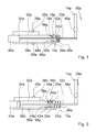
- FIG. 1 shows a schematic representation of an aircraft seat with an aircraft seat device according to the invention and an indicated passenger 28a before a crash in an aircraft.
- the aircraft seat apparatus has a seat back impact protection unit 10a, which is provided to reduce impact forces 12a on a rear side of a backrest 14a of the aircraft seat in the event of a crash.
- the seat back guard unit 10a has an actuator 16a designed to initiate a backup operation.
- the actuating unit 16a has a backrest force independent crash sensor unit 18, which comprises an acceleration sensor.
- the setting unit 16a has an actuator unit 20a, which is intended to initiate a setting process.
- the actuator unit 20a and the crash sensor unit 18a are partially formed in one piece, and indeed the actuator unit 20a and the crash sensor unit 18a have a common, one-piece mass element 30a.
- the aircraft seat has a legislative aid 26 a, which is designed as a so-called Hydrolock and allows a backrest lock the backrest 14 a in different angular positions.
- the Hydrolock comprises an adjusting cylinder 32a and a displaceably mounted in the adjusting cylinder 32a piston 34a.
- the piston 34a is connected via a piston rod 22a to a lower side of the backrest 14a.
- the The wholehnenverstelltician 26 a has a valve unit 36 a, of the passenger 28a is actuated by means of an actuating element, not shown, so that during an adjustment, the valve unit 36a opened and liquid can flow via the valve unit 36a from a chamber 38a in front of the piston 34a in a chamber 40a behind the piston 34a or vice versa.
- a liquid instead of a liquid, other fluid media are conceivable, in particular air.
- the seat back guard unit 10a is partially formed integrally with the seat back adjusting unit 26a by supporting the mass member 30a in the adjusting cylinder 32a.
- the researcherlehnenaufschlagêtêtrioshowsaku 10a and the researcherslehnenverstelltechnik 26a thus have the common adjusting cylinder 32a.
- the mass element 30a is part of a valve unit 24a of the seat back guard unit 10a and part of a trip unit of the seat back guard unit 10a, which is intended to cancel a backrest lock the thoroughlylehnenverstelltechnik 26a.
- the mass element 30a seals in its initial position before a crash from a bypass channel 44a of the scholarlehnenaufschlagêt Kunststoffstechnik 10a, which connects the chambers 38a, 40a within the adjusting cylinder 32a.
- the mass element 30a is secured in its initial position by means of a spring element 46a. In an initial position of the mass element 30a, the spring element 46a is stress-free and can absorb tensile and compressive forces to secure the starting position of the mass element 30a outside of a crash.
- the spring element 46a is provided to release the bypass channel 44a only after a certain acceleration threshold value.
- the adjusting unit 16a also comprises an adjusting unit 56a, which is provided to set parameters, namely a damping characteristic and a parameter for the acceleration threshold value, from which the actuating unit 16a triggers the securing operation.
- the adjustment unit 56a has a throttle unit 58a arranged in a through-channel 62a of the mass element 30a, which opens only at a certain, adjustable pressure, so that liquid can flow through the through-channel 62a of the mass element 30a and the mass element 30a can be displaced.
- the adjustment unit 56a could have an adjustable throttle unit 60a in the bypass channel 44 and / or also comprise other adjustment elements that appear appropriate to the person skilled in the art, such as a setting element for adjustment
- the mass element 30a further mass elements can be added and / or that it is designed to be interchangeable in order to achieve adjustability of a spring force of the spring element 46a and a frictional force of the mass element 30a within the adjusting cylinder 32a.
- acceleration forces 42a act on the mass element 30a (FIG. FIG. 2 ). If a certain pressure on the throttle unit 58a is exceeded, this is opened and the mass member 30a, driven by the acceleration forces 42a, against a spring force of the spring member 46a moves out of its initial position, whereby the partially formed by the mass member 30a with valve unit 24a and thus the bypass channel 44 is opened and the seat back latch is released. As a result of the acceleration forces 42a acting on the mass element 30a, the spring element 46a is overstretched so that the mass element 30a keeps the bypass channel 44a open even after the acceleration forces 42a have dropped. The spring element 46a thus forms a holding unit, which is provided to keep the mass element 30a in its position remote from the backrest 14a and the valve unit 24a after the crash event.
- liquid can flow from the chamber 38a via the bypass channel 44a into the chamber 40a, the piston 34a can be displaced within the adjusting cylinder 32a in the direction of the backrest 14a, and the backrest 14a can be pivoted about a pivot point 48a with its upper end forward, ie in a direction away from the passenger 28a, whereby the impact force 12a of the passenger 28a or the head of the passenger 28a on the rear side of the backrest 14a can be damped (FIG. FIG. 3 ).
- the backrest 14a can be moved back to its original position, wherein liquid flows from the chamber 40a via the bypass passage 44a into the chamber 38a.
- FIG. 4 a further embodiment of the invention is shown.
- the following descriptions are essentially limited to the differences between the embodiments, with respect to the same components, features and functions on the description of the embodiment of FIGS. 1 to 3 can be referenced.
- the letter a in the reference numerals of the embodiment in the FIGS. 1 to 3 by the letter b in the reference numerals of the embodiment of FIG. 4 replaced.
- With respect to identically designated components in particular with regard to components with the same reference numerals, can in principle also to the drawings and / or the description of the embodiment of FIGS. 1 to 3 to get expelled.
- the FIG. 4 shows an aircraft seat device with a consultlehnenaufschlagêtsappel 10 b, which includes an actuator 16 b.
- the actuating unit 16b has a backrest force independent crash sensor unit 18b with an acceleration sensor comprising a mass element 30b.
- the crash sensor unit 18b also has a catching unit 50b, which is provided to hold the mass element 30b in its initial position before a crash and to catch and hold the mass element 30b in an end position after the crash and after a phase of movement of the mass element 30b this in FIG. 4 is indicated.
- the catching unit 50b has two spaced elastic members 52b, 54b fixedly mounted in an adjusting cylinder 32b of a seat back adjusting unit 26b of the aircraft seat apparatus.
- the element 52b is compressed in the radial direction.
- the mass element 30b is released and can be displaced in a direction away from a backrest 14b direction within the adjusting cylinder 32b.
- the element 54b is deformed by the mass element 30b in the radial direction, so that the mass element 30b can be caught in its end position.
- corresponding to the mass element 30b corresponding inclined surfaces are formed.
- the catching unit 50b thus forms a holding unit which is provided to keep the mass element 30b in its position remote from the backrest 14b and the valve unit 24b open after the crash.
Abstract
Description
Die Erfindung geht aus von einer Sitzvorrichtung nach dem Oberbegriff des Anspruchs 1.The invention relates to a seat device according to the preamble of claim 1.
Es ist bereits eine Flugzeugsitzvorrichtung mit einer Rückenlehnenaufschlagssicherungseinheit bekannt, die dazu vorgesehen ist, Aufschlagkräfte auf eine Rückenlehne in einem Crashfall zu reduzieren. Die Rückenlehnenaufschlagssicherungseinheit weist hierfür einen Scherpin auf, der bei einem Aufschlagen eines Gegenstands, insbesondere eines Kopfs eines Passagiers, auf eine Rückseite der Rückenlehne abgeschert wird und eine Verriegelung der Rückenlehne aufhebt.There is already known an aircraft seat device with a seat back impact protection unit, which is intended to reduce impact forces on a backrest in the event of a crash. For this purpose, the backrest impact protection unit has a shear pin, which is sheared off when a subject, in particular a head of a passenger, hits a back of the backrest and cancels a locking of the backrest.
Die Erfindung geht aus von einer Sitzvorrichtung, insbesondere einer Flugzeugsitzvorrichtung, mit einer Rückenlehnenaufschlagssicherungseinheit, die dazu vorgesehen ist, Aufschlagkräfte auf eine Rückenlehne in einem Crashfall zumindest teilweise zu reduzieren.The invention is based on a seat device, in particular an aircraft seat device, with a seat back impact protection unit which is provided to at least partially reduce impact forces on a backrest in the event of a crash.
Es wird vorgeschlagen, dass die Rückenlehnenaufschlagssicherungseinheit eine Stelleinheit aufweist, die zumindest dazu vorgesehen ist, einen Sicherungsvorgang einzuleiten. Unter einer "Stelleinheit" soll dabei insbesondere eine Einheit verstanden werden, die an einem Stellvorgang zumindest beteiligt ist, abweichend von einem reinen Scherbolzen ausgebildet ist und/oder insbesondere eine Elektronikeinheit, eine Sensoreinheit und/oder eine Aktoreinheit aufweist. Unter "vorgesehen" soll hierbei insbesondere speziell ausgebildet, ausgestattet und/oder programmiert verstanden werden. Unter einem "Sicherungsvorgang" soll dabei insbesondere ein Vorgang verstanden werden, der dazu vorgesehen ist, eine Aufprallkraft zu reduzieren und/oder zu dämpfen. Durch eine entsprechende Ausgestaltung kann eine Sitzvorrichtung besonders vorteilhaft für verschiedene Lastfälle und/oder für unterschiedliche Anforderungen ausgelegt werden.It is proposed that the backrest serve securing unit has an actuating unit which is at least provided to initiate a securing operation. An "actuating unit" should be understood to mean, in particular, a unit which is at least involved in a setting process, deviating from a pure shear bolt and / or in particular has an electronic unit, a sensor unit and / or an actuator unit. By "provided" is meant in this case in particular specially designed, equipped and / or programmed. In this context, a "securing operation" should be understood in particular to mean an operation which is intended to reduce and / or dampen an impact force. By a corresponding embodiment, a seat device can be designed particularly advantageous for different load cases and / or for different requirements.
Weist die Stelleinheit zumindest eine zumindest weitgehend rückenlehnenkraftunabhängige Crashsensoreinheit auf, können verschiedene Lastaufnahmen besonders vorteilhaft differenziert werden. Unter "rückenlehnenkraftunabhängig" soll dabei insbesondere verstanden werden, dass die Sensoreinheit dazu vorgesehen ist, unabhängig von einer an der Rückenlehne angreifenden Kraft, wie insbesondere unabhängig von einer an der Rückenlehne angreifenden Haltekraft eines Passagiers, einen Crashfall zu sensieren, und zwar insbesondere, indem die Sensoreinheit dazu vorgesehen ist, eine auf ein von der Rückenlehne differierendes Bauteil wirkende Kraft und/oder besonders vorteilhaft eine Beschleunigungskraft zu sensieren. Alternativ oder zusätzlich könnte die Stelleinheit auch dazu vorgesehen sein, ein Sensorsignal von einer dritten Einheit, die einen Crashsensor aufweist, zu verarbeiten.If the actuating unit has at least one crash sensor unit which is independent of at least largely backrest force, different load receptacles can be differentiated in a particularly advantageous manner. The term "backrest force independent" is to be understood in particular as meaning that the sensor unit is intended to sense a crash independently of a force acting on the backrest, such as, in particular, a holding force of a passenger acting on the backrest Sensor unit is provided to sense a force acting on a differing from the backrest component force and / or particularly advantageous to detect an acceleration force. Alternatively or additionally, the setting unit could also be provided to process a sensor signal from a third unit having a crash sensor.
Die Crashsensoreinheit kann dabei verschiedene, dem Fachmann als sinnvoll erscheinende Sensoren aufweisen, wie beispielsweise Kraftsensoren, Drucksensoren usw. Besonders vorteilhaft weist die Crashsensoreinheit jedoch zumindest einen Beschleunigungssensor auf, wodurch besonders vorteilhaft eine Beschleunigung sensiert werden kann, mittels der vorzugsweise eindeutig auf einen Crashfall geschlossen werden kann. Zudem kann ein unerwünschtes Auslösen bei zumindest weitgehend statischen Kräften vorzugsweise vermieden werden. Besonders vorteilhaft ist die Crashsensoreinheit dazu vorgesehen, eine auf ein von der Rückenlehne differierendes Bauteil wirkende Beschleunigungskraft zu sensieren. Besonders vorteilhaft ist die Crashsensoreinheit dazu ausgelegt, erst ein Signal oberhalb eines Beschleunigungsschwellwerts und/oder einen Stellvorgang auszulösen, wie vorzugsweise oberhalb eines Beschleunigungswerts, der zu einer Vervierfachung einer Gewichtskraft und insbesondere zu einer Verachtfachung einer Gewichtskraft führt.In this case, the crash sensor unit can have various sensors that appear appropriate to the person skilled in the art, such as force sensors, pressure sensors, etc. However, the crash sensor unit particularly advantageously has at least one acceleration sensor, whereby an acceleration can be sensed with particular advantage, by means of which it is preferably unequivocally concluded that there has been a crash can. In addition, an undesired triggering at least largely static forces are preferably avoided. Particularly advantageously, the crash sensor unit is provided to sense an acceleration force acting on a component that differs from the backrest. Particularly advantageously, the crash sensor unit is designed to first trigger a signal above an acceleration threshold value and / or an actuating process, such as preferably above an acceleration value which leads to a quadrupling of a weight force and in particular to an eightfold increase in a weight force.
Weist die Stelleinheit eine Aktoreinheit auf, die dazu vorgesehen ist, einen Stellvorgang einzuleiten, kann die Stelleinheit besonders flexibel gestaltet werden. Unter einer "Aktoreinheit" soll dabei eine Einheit verstanden werden, die dazu vorgesehen ist, eine Stellbewegung zu erzeugen, wie insbesondere eine Stellbewegung zum Öffnen eines Ventils und/oder zur Bewegung eines Elements, wie insbesondere eines Verriegelungselements.If the setting unit has an actuator unit which is intended to initiate a setting process, the setting unit can be made particularly flexible. An "actuator unit" is to be understood as a unit which is intended to generate an adjusting movement, such as, in particular, an adjusting movement for opening a valve and / or for moving an element, in particular a locking element.
In einer weiteren Ausgestaltung wird vorgeschlagen, dass die Aktoreinheit und die Crashsensoreinheit zumindest teilweise einstückig ausgebildet sind, wodurch zusätzliche Bauteile, Bauraum und Gewicht eingespart werden können. Unter "einstückig" soll insbesondere zumindest stoffschlüssig verbunden verstanden werden, beispielsweise durch einen Schweißprozess, einen Klebeprozess, einen Anspritzprozess und/oder einen anderen, dem Fachmann als sinnvoll erscheinenden Prozess, und/oder vorteilhaft in einem Stück geformt verstanden werden, wie beispielsweise durch eine Herstellung aus einem Guss und/oder durch eine Herstellung in einem Ein- oder Mehrkomponentenspritzverfahren, und vorteilhaft aus einem einzelnen Rohling. Unter "zumindest teilweise einstückig" soll dabei insbesondere verstanden werden, dass zumindest ein Bauteil der Aktoreinheit und ein Bauteil der Crashsensoreinheit einstückig ausgebildet sind.In a further embodiment, it is proposed that the actuator unit and the crash sensor unit are at least partially formed in one piece, whereby additional components, space and weight can be saved. By "one piece" should be understood in particular at least materially connected connected, for example, by a welding process, a gluing process, a Anspritzprozess and / or another, the skilled person appear useful process, and / or advantageously formed in one piece, such as by a Manufacture from a casting and / or by a production in a one- or multi-component injection molding process, and advantageously from a single blank. By "at least partially in one piece" is to be understood in particular that at least one component of the actuator unit and a component of the crash sensor unit are integrally formed.
Zur Reduzierung von Aufschlagkräften auf eine Rückenlehne sind verschiedene, dem Fachmann als sinnvoll erscheinende Vorgänge denkbar, beispielsweise kann eine Rückseite einer Rückenlehne und insbesondere ein Aufschlagbereich in ihrer bzw. in seiner Steifigkeit verändert werden, beispielsweise, indem in einem vorgesehenen Druckpolster Druck abgelassen wird, ein Materialwert verändert wird, ein Dämpfungselement in einen Aufschlagbereich verschoben wird und/oder indem ein steifes Element aus einem Aufschlagbereich entfernt wird. Besonders konstruktiv einfach kann dies jedoch erreicht werden, indem die Rückenlehnenaufschlagssicherungseinheit zumindest eine Auslöseeinheit aufweist, die dazu vorgesehen ist, eine Rückenlehnenverriegelung zumindest teilweise aufzuheben. Die Rückenlehnenverriegelungseinheit dient insbesondere dazu, die Rückenlehne in einer bestimmten, vorzugsweise einstellbaren, Winkelstellung zu halten.To reduce impact forces on a backrest different, the skilled person appear reasonable operations conceivable, for example, a back of a backrest and in particular a service area in its or in its stiffness to be changed, for example, by in a designated pressure pad pressure is released, a Material value is changed, a damping element is moved into a service area and / or by a rigid element is removed from a service area. However, this can be achieved in a structurally simple manner in that the backrest serve securing unit has at least one release unit which is provided to at least partially lift a backrest lock. The backrest locking unit serves in particular to hold the backrest in a specific, preferably adjustable, angular position.
Weist die Rückenlehnenaufschlagssicherungseinheit wenigstens eine Ventileinheit auf, können besonders vorteilhaft gewichtssparend Stellvorgänge realisiert werden. Grundsätzlich sind jedoch auch andere, dem Fachmann als sinnvoll erscheinende Stellelemente denkbar.If the backrest opening safety unit has at least one valve unit, positioning processes can be realized in a particularly advantageous manner in a weight-saving manner. In principle, however, other, the expert appear reasonable sense control elements are conceivable.
Umfasst die Sitzvorrichtung eine Rückenlehnenverstelleinheit, die zumindest teilweise einstückig mit der Rückenlehnenaufschlagssicherungseinheit ausgebildet ist, können wiederum Bauteile, Bauraum und Gewicht eingespart werden. Dabei soll unter einer "Rückenlehnenverstelleinheit" insbesondere eine Einheit verstanden werden, die dazu vorgesehen ist, eine Rückenlehne von einem Bediener in verschiedenen Winkelstellungen einstellbar auszuführen.If the seat device comprises a backrest adjustment unit which is formed at least partially in one piece with the backrest deployment safety unit, in turn components, space and weight can be saved. In this case, a "Rückenlehnenverstelleinheit" is to be understood in particular a unit that is provided to perform a backrest of an operator adjustable in different angular positions.
In einer weiteren Ausgestaltung der Erfindung wird vorgeschlagen, dass die Stelleinheit eine Halteeinheit aufweist, die dazu vorgesehen ist, wenigstens ein Stellelement der Stelleinheit nach einem Crashfall in einer Stellung zu halten. Durch eine entsprechende Ausgestaltung kann ein ungewünschtes Sperren vermieden werden. Das Stellelement kann dabei von verschiedenen, dem Fachmann als sinnvoll erscheinenden Elementen gebildet sein, wie beispielsweise von einem Ventilelement, einem Massenelement usw.In a further embodiment of the invention, it is proposed that the setting unit has a holding unit which is provided to hold at least one adjusting element of the setting unit in a position after a crash. By an appropriate design, an unwanted locking can be avoided. The control element can be formed by various, the skilled person appear useful elements, such as a valve element, a mass element, etc.
Ferner wird vorgeschlagen, dass die Stelleinheit eine Einstelleinheit umfasst, die dazu vorgesehen ist, zumindest eine Kenngröße einzustellen. Dabei ist denkbar, dass mittels der Einstelleinheit verschiedene, dem Fachmann als sinnvoll erscheinende Kenngrößen einstellbar ausgebildet werden. Besonders vorteilhaft sind jedoch eine Dämpfungskenngröße und/oder eine Kenngröße für einen Beschleunigungsschwellwert einstellbar, ab dem die Stelleinheit den Sicherungsvorgang auslöst. Die Einstelleinheit kann hierbei verschiedene Stellelemente aufweisen, wie beispielsweise ein Stellelement zur Einstellung einer Federkraft, einer Reibkraft, einer Druckkraft zum Öffnen eines Ventils, und/oder es könnte auch eine Masse eines Massenelements einstellbar ausgeführt werden, indem diesem beispielsweise Massenelemente hinzugefügt oder auch von diesem Massenelement entfernt werden können usw.It is also proposed that the setting unit comprises an adjusting unit, which is provided to set at least one characteristic. It is conceivable that by means of the setting different, the expert appear to be useful characteristics are made adjustable. However, a damping characteristic variable and / or a characteristic variable for an acceleration threshold value can be set with particular advantage, from which the actuating unit triggers the securing operation. The adjusting unit may in this case have different adjusting elements, such as an adjusting element for adjusting a spring force, a frictional force, a pressure force to open a valve, and / or it could also be a mass of a mass element made adjustable by this example mass elements added or from this Mass element can be removed etc.
Weitere Vorteile ergeben sich aus der folgenden Zeichnungsbeschreibung. In der Zeichnung sind Ausführungsbeispiele der Erfindung dargestellt. Die Beschreibung und die Ansprüche enthalten zahlreiche Merkmale in Kombination. Der Fachmann wird die Merkmale zweckmäßigerweise auch einzeln betrachten und zu sinnvollen weiteren Kombinationen zusammenfassen.Further advantages emerge from the following description of the drawing. In the drawings, embodiments of the invention are shown. The description and claims contain numerous features in combination. The person skilled in the art will expediently also consider the features individually and combine them into meaningful further combinations.
Es zeigen:
- Fig. 1
- eine schematische Darstellung eines Flugzeugsitzes mit einer erfindungsgemäßen Flugzeugsitzvorrichtung sowie einen angedeuteten Passagier vor einem Crashfall,
- Fig. 2
- den Flugzeugsitz und den Passagier aus
Figur 1 nach dem Crashfall in einer ersten Stellung, - Fig. 3
- den Flugzeugsitz und den Passagier aus
Figur 1 nach dem Crashfall in einer zweiten Stellung und - Fig. 4
- eine schematische Darstellung eines Flugzeugsitzes mit einer alternativen erfindungsgemäßen Flugzeugsitzvorrichtung sowie einen angedeuteten Passagier.
- Fig. 1
- a schematic representation of an aircraft seat with an aircraft seat device according to the invention and an indicated passenger in the event of a crash,
- Fig. 2
- the plane seat and the passenger
FIG. 1 after the crash in a first position, - Fig. 3
- the plane seat and the passenger
FIG. 1 after the crash in a second position and - Fig. 4
- a schematic representation of an aircraft seat with an alternative inventive aircraft seat device and an indicated passenger.
Der Flugzeugsitz weist eine Rückenlehnenverstelleinheit 26a auf, die als so genannter Hydrolock ausgebildet ist und eine Rückenlehnenverriegelung der Rückenlehne 14a in verschiedenen Winkelstellungen ermöglicht. Der Hydrolock umfasst einen Verstellzylinder 32a und einen in dem Verstellzylinder 32a verschiebbar gelagerten Kolben 34a. Der Kolben 34a ist über eine Kolbenstange 22a mit einer Unterseite der Rückenlehne 14a verbunden. Die Rückenlehnenverstelleinheit 26a weist eine Ventileinheit 36a auf, die von dem Passagier 28a mittels eines nicht näher dargestellten Betätigungselements ansteuerbar ist, so dass bei einem Verstellvorgang die Ventileinheit 36a geöffnet und Flüssigkeit über die Ventileinheit 36a von einer Kammer 38a vor dem Kolben 34a in eine Kammer 40a hinter dem Kolben 34a oder umgekehrt strömen kann. Anstatt einer Flüssigkeit sind auch andere strömungsfähige Medien denkbar, wie insbesondere Luft. Die Rückenlehnenaufschlagssicherungseinheit 10a ist teilweise einstückig mit der Rückenlehnenverstelleinheit 26a ausgebildet, und zwar indem das Massenelement 30a in dem Verstellzylinder 32a gelagert ist. Die Rückenlehnenaufschlagssicherungseinheit 10a und die Rückenlehnenverstelleinheit 26a weisen damit den gemeinsamen Verstellzylinder 32a auf.The aircraft seat has a Rückenlehnenverstelleinheit 26 a, which is designed as a so-called Hydrolock and allows a backrest lock the
Das Massenelement 30a ist Teil einer Ventileinheit 24a der Rückenlehnenaufschlagssicherungseinheit 10a sowie Teil einer Auslöseeinheit der Rückenlehnenaufschlagssicherungseinheit 10a, die dazu vorgesehen ist, eine Rückenlehnenverriegelung der Rückenlehnenverstelleinheit 26a aufzuheben. Das Massenelement 30a dichtet in seiner Ausgangsstellung vor einem Crashfall einen Bypasskanal 44a der Rückenlehnenaufschlagssicherungseinheit 10a ab, der die Kammern 38a, 40a innerhalb des Verstellzylinders 32a verbindet. Das Massenelement 30a ist in seiner Ausgangsstellung mittels eines Federelements 46a gesichert. In einer Ausgangsstellung des Massenelements 30a ist das Federelement 46a spannungsfrei und kann zur Sicherung der Ausgangsstellung des Massenelements 30a außerhalb eines Crashfalls Zug- und Druckkräfte aufnehmen. Das Federelement 46a ist dazu vorgesehen, den Bypasskanal 44a erst ab einem bestimmten Beschleunigungsschwellwert freizugegeben.The
Die Stelleinheit 16a umfasst zudem eine Einstelleinheit 56a, die dazu vorgesehen ist, Kenngrößen einzustellen, und zwar eine Dämpfungskenngröße und eine Kenngröße für den Beschleunigungsschwellwert, ab dem die Stelleinheit 16a den Sicherungsvorgang auslöst. Die Einstelleinheit 56a weist eine, in einem Durchgangskanal 62a des Massenelements 30a angeordnete Drosseleinheit 58a auf, die erst ab einem bestimmten, einstellbaren Druck öffnet, so dass durch den Durchgangskanal 62a des Massenelements 30a Flüssigkeit strömen und das Massenelement 30a verschoben werden kann. Alternativ und/oder zusätzlich könnte die Einstelleinheit 56a eine einstellbare Drosseleinheit 60a im Bypasskanal 44 aufweisen und/oder auch andere, dem Fachmann als sinnvoll erscheinende Einstellelemente umfassen, wie beispielsweise ein Einstellelement zur Einstellung einer Federkraft des Federelements 46a und einer Reibkraft des Massenelements 30a innerhalb des Verstellzylinders 32a usw. Ferner wäre auch denkbar, dass dem Massenelement 30a weitere Massenelemente hinzugefügt werden können und/oder dass dieses austauschbar ausgeführt ist, um eine Einstellbarkeit zu erreichen. Grundsätzlich ist jedoch auch denkbar, die Sitzvorrichtung ohne die Einstelleinheit 56a auszuführen, so dass die Flüssigkeit frei durch den Durchgangskanal 62a des Massenelements 30a strömen kann.The adjusting
Tritt ein Crashfall auf und wird das Flugzeug verzögert, wirken auf das Massenelement 30a Beschleunigungskräfte 42a (
Trifft der Passagier 28a nun auf die Rückseite der vor ihm befindlichen Rückenlehne 14a, kann Flüssigkeit von der Kammer 38a über den Bypasskanal 44a in die Kammer 40a strömen, der Kolben 34a kann innerhalb des Verstellzylinders 32a in Richtung der Rückenlehne 14a verschoben werden, und die Rückenlehne 14a kann um einen Schwenkpunkt 48a mit ihrem oberen Ende nach vorne, d.h. in eine vom Passagier 28a abgewandte Richtung geschwenkt werden, wodurch die Aufschlagskraft 12a des Passagiers 28a bzw. des Kopfs des Passagiers 28a auf der Rückseite der Rückenlehne 14a gedämpft werden kann (
Nach dem Crashfall kann die Rückenlehne 14a wieder in ihre Ausgangsstellung zurückbewegt werden, wobei Flüssigkeit von der Kammer 40a über den Bypasskanal 44a in die Kammer 38a strömt.After the crash, the
In der
Die
- 1010
- RückenlehnenaufschlagssicherungseinheitBackrests surcharge security unit
- 1212
- Aufschlagkraftimpact force
- 1414
- Rückenlehnebackrest
- 1616
- Stelleinheitactuator
- 1818
- CrashsensoreinheitCrash sensor unit
- 2020
- Aktoreinheitactuator
- 2222
- Kolbenstangepiston rod
- 2424
- Ventileinheitvalve unit
- 2626
- RückenlehnenverstelleinheitRückenlehnenverstelleinheit
- 2828
- Passagierpassenger
- 3030
- Massenelementmass element
- 3232
- Verstellzylinderadjusting cylinder
- 3434
- Kolbenpiston
- 3636
- Ventileinheitvalve unit
- 3838
- Kammerchamber
- 4040
- Kammerchamber
- 4242
- Beschleunigungskraftaccelerating force
- 4444
- Bypasskanalbypass channel
- 4646
- Federelementspring element
- 4848
- Schwenkpunktpivot point
- 5050
- FangeinheitFang unit
- 5252
- Elementelement
- 5454
- Elementelement
- 5656
- Einstelleinheitadjustment
- 5858
- Drosseleinheitrestrictor
- 6060
- Drosseleinheitrestrictor
- 6262
- DurchgangskanalThrough channel
Claims (12)
dadurch gekennzeichnet, dass die Rückenlehnenaufschlagssicherungseinheit (10a; 10b) eine Stelleinheit (16a; 16b) aufweist, die zumindest dazu vorgesehen ist, einen Sicherungsvorgang einzuleiten.Seat device, in particular aircraft seat device, with a seat back impact protection unit (10a, 10b) which is provided to at least partially reduce impact forces (12a, 12b) on a backrest (14a, 14b) in the event of a crash,
characterized in that the Rückenlehnenaufschlagsicherseinheit (10a, 10b) has an actuating unit (16a, 16b), which is at least provided to initiate a backup operation.
dadurch gekennzeichnet, dass die Stelleinheit (16a; 16b) zumindest eine zumindest weitgehend rückenlehnenkraftunabhängige Crashsensoreinheit (18a; 18b) aufweist.Seat device according to claim 1,
characterized in that the setting unit (16a, 16b) has at least one crash sensor unit (18a, 18b) which is independent of at least substantially backrest force.
dadurch gekennzeichnet, dass die Crashsensoreinheit (18a; 18b) zumindest einen Beschleunigungssensor aufweist.Seat device according to claim 2,
characterized in that the crash sensor unit (18a; 18b) has at least one acceleration sensor.
dadurch gekennzeichnet, dass die Stelleinheit (16a; 16b) eine Aktoreinheit (20a; 20b) aufweist, die dazu vorgesehen ist, einen Stellvorgang einzuleiten.Seating device according to claim 2 or 3,
characterized in that the setting unit (16a, 16b) has an actuator unit (20a, 20b) which is intended to initiate a setting process.
dadurch gekennzeichnet, dass die Aktoreinheit (20a; 20b) und die Crashsensoreinheit (18a; 18b) zumindest teilweise einstückig ausgebildet sind.Seat device according to claim 4,
characterized in that the actuator unit (20a; 20b) and the crash sensor unit (18a; 18b) are formed at least partially in one piece.
dadurch gekennzeichnet, dass die Rückenlehnenaufschlagssicherungseinheit (10a; 10b) zumindest eine Auslöseeinheit aufweist, die dazu vorgesehen ist, eine Rückenlehnenverriegelung zumindest teilweise aufzuheben.Seating device according to one of the preceding claims,
characterized in that the Rückenlehnenaufschlagsicherseinheit (10a, 10b) has at least one release unit, which is intended to at least partially cancel a backrest lock.
dadurch gekennzeichnet, dass die Rückenlehnenaufschlagssicherungseinheit (10a; 10b) wenigstens eine Ventileinheit (24a; 24b) aufweist.Seating device according to one of the preceding claims,
characterized in that the Rückenlehnenaufschlagsicherseinheit (10a, 10b) comprises at least one valve unit (24a, 24b).
gekennzeichnet durch eine Rückenlehnenverstelleinheit (26a; 26b), die zumindest teilweise einstückig mit der Rückenlehnenaufschlagssicherungseinheit (10a; 10b) ausgebildet ist.Seating device according to one of the preceding claims,
characterized by a backrest adjustment unit (26a; 26b) at least partially integral with the backrest deployment safety unit (10a; 10b).
dadurch gekennzeichnet, dass die Stelleinheit (16a; 16b) eine Halteeinheit aufweist, die dazu vorgesehen ist, wenigstens ein Stellelement der Stelleinheit (16a; 16b) nach einem Crashfall in einer Stellung zu halten.Seating device according to one of the preceding claims,
characterized in that the setting unit (16a, 16b) has a holding unit which is provided to hold at least one adjusting element of the setting unit (16a, 16b) in a position after a crash.
dadurch gekennzeichnet, dass die Stelleinheit (16a; 16b) eine Einstelleinheit (56a; 56b) umfasst, die dazu vorgesehen ist, zumindest eine Kenngröße einzustellen.Seating device according to one of the preceding claims,
characterized in that the setting unit (16a; 16b) comprises an adjusting unit (56a; 56b) which is provided to set at least one characteristic.
Applications Claiming Priority (1)
| Application Number | Priority Date | Filing Date | Title |
|---|---|---|---|
| DE102011122186A DE102011122186A1 (en) | 2011-12-27 | 2011-12-27 | seat device |
Publications (3)
| Publication Number | Publication Date |
|---|---|
| EP2610178A2 true EP2610178A2 (en) | 2013-07-03 |
| EP2610178A3 EP2610178A3 (en) | 2017-04-12 |
| EP2610178B1 EP2610178B1 (en) | 2018-10-31 |
Family
ID=47561155
Family Applications (1)
| Application Number | Title | Priority Date | Filing Date |
|---|---|---|---|
| EP12198140.1A Not-in-force EP2610178B1 (en) | 2011-12-27 | 2012-12-19 | Seating device |
Country Status (2)
| Country | Link |
|---|---|
| EP (1) | EP2610178B1 (en) |
| DE (1) | DE102011122186A1 (en) |
Cited By (6)
| Publication number | Priority date | Publication date | Assignee | Title |
|---|---|---|---|---|
| WO2016001374A1 (en) * | 2014-07-02 | 2016-01-07 | Recaro Aircraft Seating Gmbh & Co. Kg | Aircraft seat device |
| GB2561548A (en) * | 2017-03-31 | 2018-10-24 | Acro Aircraft Seating Ltd | Energy absorbing device |
| US10239420B2 (en) | 2016-12-19 | 2019-03-26 | Lear Corporation | System and method for positioning a vehicle seat |
| WO2019077081A1 (en) * | 2017-10-18 | 2019-04-25 | Recaro Aircraft Seating Gmbh & Co. Kg | Aircraft seat device with multi-point restraint unit |
| WO2019201604A1 (en) * | 2018-04-19 | 2019-10-24 | Safran Seats | System for unlocking a seat backrest by inertia |
| CN110775085A (en) * | 2017-11-06 | 2020-02-11 | 北京交通大学 | Safety seat with ball unlocking mechanism |
Families Citing this family (1)
| Publication number | Priority date | Publication date | Assignee | Title |
|---|---|---|---|---|
| DE102017117175A1 (en) * | 2017-07-28 | 2019-01-31 | Recaro Aircraft Seating Gmbh & Co. Kg | Aircraft seat device |
Family Cites Families (4)
| Publication number | Priority date | Publication date | Assignee | Title |
|---|---|---|---|---|
| DE19839323C1 (en) * | 1998-08-28 | 1999-12-30 | Vogel Ind Gmbh | Seat for personnel transport vehicle |
| US6312049B1 (en) * | 1999-07-01 | 2001-11-06 | Ford Global Technologies, Inc. | Programmable seat back damper assembly for seats |
| US20020145315A1 (en) * | 2000-10-25 | 2002-10-10 | Fraley Gregory S. | Energy management device for vehicle |
| GB2409255B (en) * | 2003-12-19 | 2006-05-31 | Lear Corp Inc | A vehicle seat adjustment system including an occupant protection adjustment |
-
2011
- 2011-12-27 DE DE102011122186A patent/DE102011122186A1/en not_active Withdrawn
-
2012
- 2012-12-19 EP EP12198140.1A patent/EP2610178B1/en not_active Not-in-force
Non-Patent Citations (1)
| Title |
|---|
| None |
Cited By (17)
| Publication number | Priority date | Publication date | Assignee | Title |
|---|---|---|---|---|
| EP3164331B1 (en) * | 2014-07-02 | 2020-03-18 | Recaro Aircraft Seating GmbH & Co. KG | Aircraft seat device |
| WO2016001375A1 (en) * | 2014-07-02 | 2016-01-07 | Recaro Aircraft Seating Gmbh & Co. Kg | Airplane seat device |
| WO2016001374A1 (en) * | 2014-07-02 | 2016-01-07 | Recaro Aircraft Seating Gmbh & Co. Kg | Aircraft seat device |
| US10239420B2 (en) | 2016-12-19 | 2019-03-26 | Lear Corporation | System and method for positioning a vehicle seat |
| GB2561548A (en) * | 2017-03-31 | 2018-10-24 | Acro Aircraft Seating Ltd | Energy absorbing device |
| GB2561548B (en) * | 2017-03-31 | 2019-07-17 | Acro Aircraft Seating Ltd | Energy absorbing device |
| US10858109B2 (en) | 2017-03-31 | 2020-12-08 | Acro Aircraft Seating Limited | Energy absorbing device |
| WO2019077081A1 (en) * | 2017-10-18 | 2019-04-25 | Recaro Aircraft Seating Gmbh & Co. Kg | Aircraft seat device with multi-point restraint unit |
| EP4249323A3 (en) * | 2017-10-18 | 2023-11-15 | Recaro Aircraft Seating GmbH & Co. KG | Aircraft seat row with multi-point restraint units |
| CN110775085A (en) * | 2017-11-06 | 2020-02-11 | 北京交通大学 | Safety seat with ball unlocking mechanism |
| CN110789553A (en) * | 2017-11-06 | 2020-02-14 | 北京交通大学 | Safety seat with backrest forward-leaning buffering energy-absorbing device |
| CN110789554A (en) * | 2017-11-06 | 2020-02-14 | 北京交通大学 | Safety seat with hinge unlocking mechanism |
| CN110775085B (en) * | 2017-11-06 | 2020-12-08 | 北京交通大学 | Safety seat with ball unlocking mechanism |
| CN110789553B (en) * | 2017-11-06 | 2021-04-06 | 北京交通大学 | Safety seat with backrest forward-leaning buffering energy-absorbing device |
| FR3080364A1 (en) * | 2018-04-19 | 2019-10-25 | Zodiac Seats France | SYSTEM FOR INERTIALLY UNLOCKING A SEAT BACK |
| US11352140B2 (en) | 2018-04-19 | 2022-06-07 | Safran Seats | System for the inertial unlocking of a seat back |
| WO2019201604A1 (en) * | 2018-04-19 | 2019-10-24 | Safran Seats | System for unlocking a seat backrest by inertia |
Also Published As
| Publication number | Publication date |
|---|---|
| DE102011122186A1 (en) | 2013-07-11 |
| EP2610178B1 (en) | 2018-10-31 |
| EP2610178A3 (en) | 2017-04-12 |
Similar Documents
| Publication | Publication Date | Title |
|---|---|---|
| EP2610178B1 (en) | Seating device | |
| EP2096007B1 (en) | Pedestrian protection device at the front bonnet of a motor vehicle | |
| EP3164331B1 (en) | Aircraft seat device | |
| WO1999060266A1 (en) | Pressure limitation valve | |
| DE102009040413A1 (en) | Safety mechanism for lifting e.g. front flap of outer shell of vehicle during person collision, has hinge for guidance of component, and coupling arranged between upper hinge upper part and lower hinge upper part by connecting device | |
| DE102009007179A1 (en) | Air bag arrangement for vehicle occupant-restraint system in vehicle seat, has inflation device inflating inflatable area with high internal pressure such that force is exerted on one body region of occupant during impact of occupant | |
| EP2394870A1 (en) | Spring device on a pivoting flap of a motor vehicle | |
| EP2384960A1 (en) | Protection device for attachment to a handle | |
| DE10305685B4 (en) | Pedestrian protection device on a motor vehicle | |
| DE19649836A1 (en) | Gas spring used as e.g. lifting aid for hinged cover of vehicle | |
| EP2172134B1 (en) | Armrest | |
| DE102008011325B4 (en) | Headrest for vehicle seats | |
| DE602004000593T2 (en) | Pyrotechnic actuator with variable thrust | |
| DE102005052766B3 (en) | Linearly adjustable active head rest for car seat using horizontal adjusting arm has element to move it between stowed away and pulled out positions and release element to hold support in stowed position and release it on crashing | |
| WO2021008973A1 (en) | Vehicle occupant protection system and method for protecting a vehicle occupant | |
| DE10009291A1 (en) | Armrest with integrated stowage compartment for seat of motor vehicle has hinged cover closing off stowage compartment and fixed in at least one open position by locking unit activated by positive or negative acceleration of vehicle | |
| DE2417543A1 (en) | Vehicle energy absorbing steering column - has steering wheel section of column axially displaceable within column chamber | |
| DE102012007406A1 (en) | Airbag device used in motor car, has pneumatic drive that drives holder inside the housing in responsive to release signal, and release device releases strap or airbag section from retaining position | |
| DE102011075267A1 (en) | Hinge device for front door of motor vehicle, has spring element that is arranged in transmission portion | |
| DE2141148C2 (en) | Restraint device assigned to the instrument panel of a motor vehicle | |
| WO2004076248A1 (en) | Belt force limiter for a safety belt | |
| DE10155661A1 (en) | Protection device on displaceable vehicle bonnet has sensor unit for pedestrian impact activating adjusting device which releases connecting lock and has compression spring which moves up to supporting part under pressure | |
| DE202007017748U1 (en) | Pressure generation module | |
| WO2007003349A1 (en) | Restraint system | |
| DE102019208718A1 (en) | Belt force limiter for a motor vehicle and a belt lock unit and a motor vehicle with a belt force limiter according to the invention and a method for operating the belt force limiter |
Legal Events
| Date | Code | Title | Description |
|---|---|---|---|
| PUAI | Public reference made under article 153(3) epc to a published international application that has entered the european phase |
Free format text: ORIGINAL CODE: 0009012 |
|
| AK | Designated contracting states |
Kind code of ref document: A2 Designated state(s): AL AT BE BG CH CY CZ DE DK EE ES FI FR GB GR HR HU IE IS IT LI LT LU LV MC MK MT NL NO PL PT RO RS SE SI SK SM TR |
|
| AX | Request for extension of the european patent |
Extension state: BA ME |
|
| PUAL | Search report despatched |
Free format text: ORIGINAL CODE: 0009013 |
|
| AK | Designated contracting states |
Kind code of ref document: A3 Designated state(s): AL AT BE BG CH CY CZ DE DK EE ES FI FR GB GR HR HU IE IS IT LI LT LU LV MC MK MT NL NO PL PT RO RS SE SI SK SM TR |
|
| AX | Request for extension of the european patent |
Extension state: BA ME |
|
| RIC1 | Information provided on ipc code assigned before grant |
Ipc: B64D 11/06 20060101AFI20170306BHEP Ipc: B60N 2/42 20060101ALI20170306BHEP Ipc: B60N 2/23 20060101ALI20170306BHEP |
|
| 17P | Request for examination filed |
Effective date: 20171006 |
|
| RBV | Designated contracting states (corrected) |
Designated state(s): AL AT BE BG CH CY CZ DE DK EE ES FI FR GB GR HR HU IE IS IT LI LT LU LV MC MK MT NL NO PL PT RO RS SE SI SK SM TR |
|
| GRAP | Despatch of communication of intention to grant a patent |
Free format text: ORIGINAL CODE: EPIDOSNIGR1 |
|
| RIC1 | Information provided on ipc code assigned before grant |
Ipc: B60N 2/42 20060101ALI20180423BHEP Ipc: B64D 11/06 20060101AFI20180423BHEP Ipc: B60N 2/23 20060101ALI20180423BHEP |
|
| INTG | Intention to grant announced |
Effective date: 20180515 |
|
| GRAS | Grant fee paid |
Free format text: ORIGINAL CODE: EPIDOSNIGR3 |
|
| GRAA | (expected) grant |
Free format text: ORIGINAL CODE: 0009210 |
|
| AK | Designated contracting states |
Kind code of ref document: B1 Designated state(s): AL AT BE BG CH CY CZ DE DK EE ES FI FR GB GR HR HU IE IS IT LI LT LU LV MC MK MT NL NO PL PT RO RS SE SI SK SM TR |
|
| REG | Reference to a national code |
Ref country code: CH Ref legal event code: EP Ref country code: GB Ref legal event code: FG4D Free format text: NOT ENGLISH |
|
| REG | Reference to a national code |
Ref country code: AT Ref legal event code: REF Ref document number: 1059053 Country of ref document: AT Kind code of ref document: T Effective date: 20181115 |
|
| REG | Reference to a national code |
Ref country code: DE Ref legal event code: R096 Ref document number: 502012013715 Country of ref document: DE |
|
| REG | Reference to a national code |
Ref country code: IE Ref legal event code: FG4D Free format text: LANGUAGE OF EP DOCUMENT: GERMAN |
|
| REG | Reference to a national code |
Ref country code: NL Ref legal event code: MP Effective date: 20181031 |
|
| REG | Reference to a national code |
Ref country code: LT Ref legal event code: MG4D |
|
| PG25 | Lapsed in a contracting state [announced via postgrant information from national office to epo] |
Ref country code: LT Free format text: LAPSE BECAUSE OF FAILURE TO SUBMIT A TRANSLATION OF THE DESCRIPTION OR TO PAY THE FEE WITHIN THE PRESCRIBED TIME-LIMIT Effective date: 20181031 Ref country code: HR Free format text: LAPSE BECAUSE OF FAILURE TO SUBMIT A TRANSLATION OF THE DESCRIPTION OR TO PAY THE FEE WITHIN THE PRESCRIBED TIME-LIMIT Effective date: 20181031 Ref country code: PL Free format text: LAPSE BECAUSE OF FAILURE TO SUBMIT A TRANSLATION OF THE DESCRIPTION OR TO PAY THE FEE WITHIN THE PRESCRIBED TIME-LIMIT Effective date: 20181031 Ref country code: BG Free format text: LAPSE BECAUSE OF FAILURE TO SUBMIT A TRANSLATION OF THE DESCRIPTION OR TO PAY THE FEE WITHIN THE PRESCRIBED TIME-LIMIT Effective date: 20190131 Ref country code: LV Free format text: LAPSE BECAUSE OF FAILURE TO SUBMIT A TRANSLATION OF THE DESCRIPTION OR TO PAY THE FEE WITHIN THE PRESCRIBED TIME-LIMIT Effective date: 20181031 Ref country code: FI Free format text: LAPSE BECAUSE OF FAILURE TO SUBMIT A TRANSLATION OF THE DESCRIPTION OR TO PAY THE FEE WITHIN THE PRESCRIBED TIME-LIMIT Effective date: 20181031 Ref country code: ES Free format text: LAPSE BECAUSE OF FAILURE TO SUBMIT A TRANSLATION OF THE DESCRIPTION OR TO PAY THE FEE WITHIN THE PRESCRIBED TIME-LIMIT Effective date: 20181031 Ref country code: IS Free format text: LAPSE BECAUSE OF FAILURE TO SUBMIT A TRANSLATION OF THE DESCRIPTION OR TO PAY THE FEE WITHIN THE PRESCRIBED TIME-LIMIT Effective date: 20190228 Ref country code: NO Free format text: LAPSE BECAUSE OF FAILURE TO SUBMIT A TRANSLATION OF THE DESCRIPTION OR TO PAY THE FEE WITHIN THE PRESCRIBED TIME-LIMIT Effective date: 20190131 |
|
| PG25 | Lapsed in a contracting state [announced via postgrant information from national office to epo] |
Ref country code: PT Free format text: LAPSE BECAUSE OF FAILURE TO SUBMIT A TRANSLATION OF THE DESCRIPTION OR TO PAY THE FEE WITHIN THE PRESCRIBED TIME-LIMIT Effective date: 20190301 Ref country code: NL Free format text: LAPSE BECAUSE OF FAILURE TO SUBMIT A TRANSLATION OF THE DESCRIPTION OR TO PAY THE FEE WITHIN THE PRESCRIBED TIME-LIMIT Effective date: 20181031 Ref country code: RS Free format text: LAPSE BECAUSE OF FAILURE TO SUBMIT A TRANSLATION OF THE DESCRIPTION OR TO PAY THE FEE WITHIN THE PRESCRIBED TIME-LIMIT Effective date: 20181031 Ref country code: GR Free format text: LAPSE BECAUSE OF FAILURE TO SUBMIT A TRANSLATION OF THE DESCRIPTION OR TO PAY THE FEE WITHIN THE PRESCRIBED TIME-LIMIT Effective date: 20190201 Ref country code: AL Free format text: LAPSE BECAUSE OF FAILURE TO SUBMIT A TRANSLATION OF THE DESCRIPTION OR TO PAY THE FEE WITHIN THE PRESCRIBED TIME-LIMIT Effective date: 20181031 Ref country code: SE Free format text: LAPSE BECAUSE OF FAILURE TO SUBMIT A TRANSLATION OF THE DESCRIPTION OR TO PAY THE FEE WITHIN THE PRESCRIBED TIME-LIMIT Effective date: 20181031 |
|
| PG25 | Lapsed in a contracting state [announced via postgrant information from national office to epo] |
Ref country code: DK Free format text: LAPSE BECAUSE OF FAILURE TO SUBMIT A TRANSLATION OF THE DESCRIPTION OR TO PAY THE FEE WITHIN THE PRESCRIBED TIME-LIMIT Effective date: 20181031 Ref country code: IT Free format text: LAPSE BECAUSE OF FAILURE TO SUBMIT A TRANSLATION OF THE DESCRIPTION OR TO PAY THE FEE WITHIN THE PRESCRIBED TIME-LIMIT Effective date: 20181031 Ref country code: CZ Free format text: LAPSE BECAUSE OF FAILURE TO SUBMIT A TRANSLATION OF THE DESCRIPTION OR TO PAY THE FEE WITHIN THE PRESCRIBED TIME-LIMIT Effective date: 20181031 |
|
| REG | Reference to a national code |
Ref country code: CH Ref legal event code: PL |
|
| REG | Reference to a national code |
Ref country code: DE Ref legal event code: R097 Ref document number: 502012013715 Country of ref document: DE |
|
| PG25 | Lapsed in a contracting state [announced via postgrant information from national office to epo] |
Ref country code: MC Free format text: LAPSE BECAUSE OF FAILURE TO SUBMIT A TRANSLATION OF THE DESCRIPTION OR TO PAY THE FEE WITHIN THE PRESCRIBED TIME-LIMIT Effective date: 20181031 Ref country code: SK Free format text: LAPSE BECAUSE OF FAILURE TO SUBMIT A TRANSLATION OF THE DESCRIPTION OR TO PAY THE FEE WITHIN THE PRESCRIBED TIME-LIMIT Effective date: 20181031 Ref country code: EE Free format text: LAPSE BECAUSE OF FAILURE TO SUBMIT A TRANSLATION OF THE DESCRIPTION OR TO PAY THE FEE WITHIN THE PRESCRIBED TIME-LIMIT Effective date: 20181031 Ref country code: LU Free format text: LAPSE BECAUSE OF NON-PAYMENT OF DUE FEES Effective date: 20181219 Ref country code: SM Free format text: LAPSE BECAUSE OF FAILURE TO SUBMIT A TRANSLATION OF THE DESCRIPTION OR TO PAY THE FEE WITHIN THE PRESCRIBED TIME-LIMIT Effective date: 20181031 Ref country code: RO Free format text: LAPSE BECAUSE OF FAILURE TO SUBMIT A TRANSLATION OF THE DESCRIPTION OR TO PAY THE FEE WITHIN THE PRESCRIBED TIME-LIMIT Effective date: 20181031 |
|
| PLBE | No opposition filed within time limit |
Free format text: ORIGINAL CODE: 0009261 |
|
| STAA | Information on the status of an ep patent application or granted ep patent |
Free format text: STATUS: NO OPPOSITION FILED WITHIN TIME LIMIT |
|
| REG | Reference to a national code |
Ref country code: IE Ref legal event code: MM4A |
|
| REG | Reference to a national code |
Ref country code: BE Ref legal event code: MM Effective date: 20181231 |
|
| 26N | No opposition filed |
Effective date: 20190801 |
|
| PG25 | Lapsed in a contracting state [announced via postgrant information from national office to epo] |
Ref country code: SI Free format text: LAPSE BECAUSE OF FAILURE TO SUBMIT A TRANSLATION OF THE DESCRIPTION OR TO PAY THE FEE WITHIN THE PRESCRIBED TIME-LIMIT Effective date: 20181031 Ref country code: IE Free format text: LAPSE BECAUSE OF NON-PAYMENT OF DUE FEES Effective date: 20181219 |
|
| PG25 | Lapsed in a contracting state [announced via postgrant information from national office to epo] |
Ref country code: BE Free format text: LAPSE BECAUSE OF NON-PAYMENT OF DUE FEES Effective date: 20181231 |
|
| PG25 | Lapsed in a contracting state [announced via postgrant information from national office to epo] |
Ref country code: CH Free format text: LAPSE BECAUSE OF NON-PAYMENT OF DUE FEES Effective date: 20181231 Ref country code: LI Free format text: LAPSE BECAUSE OF NON-PAYMENT OF DUE FEES Effective date: 20181231 |
|
| PG25 | Lapsed in a contracting state [announced via postgrant information from national office to epo] |
Ref country code: MT Free format text: LAPSE BECAUSE OF FAILURE TO SUBMIT A TRANSLATION OF THE DESCRIPTION OR TO PAY THE FEE WITHIN THE PRESCRIBED TIME-LIMIT Effective date: 20181031 |
|
| PGFP | Annual fee paid to national office [announced via postgrant information from national office to epo] |
Ref country code: DE Payment date: 20191217 Year of fee payment: 8 |
|
| REG | Reference to a national code |
Ref country code: AT Ref legal event code: MM01 Ref document number: 1059053 Country of ref document: AT Kind code of ref document: T Effective date: 20181219 |
|
| PGFP | Annual fee paid to national office [announced via postgrant information from national office to epo] |
Ref country code: FR Payment date: 20191218 Year of fee payment: 8 |
|
| PG25 | Lapsed in a contracting state [announced via postgrant information from national office to epo] |
Ref country code: TR Free format text: LAPSE BECAUSE OF FAILURE TO SUBMIT A TRANSLATION OF THE DESCRIPTION OR TO PAY THE FEE WITHIN THE PRESCRIBED TIME-LIMIT Effective date: 20181031 |
|
| PG25 | Lapsed in a contracting state [announced via postgrant information from national office to epo] |
Ref country code: AT Free format text: LAPSE BECAUSE OF NON-PAYMENT OF DUE FEES Effective date: 20181219 |
|
| PGFP | Annual fee paid to national office [announced via postgrant information from national office to epo] |
Ref country code: GB Payment date: 20191220 Year of fee payment: 8 |
|
| PG25 | Lapsed in a contracting state [announced via postgrant information from national office to epo] |
Ref country code: CY Free format text: LAPSE BECAUSE OF FAILURE TO SUBMIT A TRANSLATION OF THE DESCRIPTION OR TO PAY THE FEE WITHIN THE PRESCRIBED TIME-LIMIT Effective date: 20181031 Ref country code: HU Free format text: LAPSE BECAUSE OF FAILURE TO SUBMIT A TRANSLATION OF THE DESCRIPTION OR TO PAY THE FEE WITHIN THE PRESCRIBED TIME-LIMIT; INVALID AB INITIO Effective date: 20121219 Ref country code: MK Free format text: LAPSE BECAUSE OF NON-PAYMENT OF DUE FEES Effective date: 20181031 |
|
| REG | Reference to a national code |
Ref country code: DE Ref legal event code: R119 Ref document number: 502012013715 Country of ref document: DE |
|
| GBPC | Gb: european patent ceased through non-payment of renewal fee |
Effective date: 20201219 |
|
| PG25 | Lapsed in a contracting state [announced via postgrant information from national office to epo] |
Ref country code: FR Free format text: LAPSE BECAUSE OF NON-PAYMENT OF DUE FEES Effective date: 20201231 |
|
| PG25 | Lapsed in a contracting state [announced via postgrant information from national office to epo] |
Ref country code: DE Free format text: LAPSE BECAUSE OF NON-PAYMENT OF DUE FEES Effective date: 20210701 Ref country code: GB Free format text: LAPSE BECAUSE OF NON-PAYMENT OF DUE FEES Effective date: 20201219 |