EP2610155A1 - Straddle-type vehicle - Google Patents
Straddle-type vehicle Download PDFInfo
- Publication number
- EP2610155A1 EP2610155A1 EP12190474.2A EP12190474A EP2610155A1 EP 2610155 A1 EP2610155 A1 EP 2610155A1 EP 12190474 A EP12190474 A EP 12190474A EP 2610155 A1 EP2610155 A1 EP 2610155A1
- Authority
- EP
- European Patent Office
- Prior art keywords
- air cleaner
- air
- rear fender
- straddle
- type vehicle
- Prior art date
- Legal status (The legal status is an assumption and is not a legal conclusion. Google has not performed a legal analysis and makes no representation as to the accuracy of the status listed.)
- Granted
Links
- 238000011045 prefiltration Methods 0.000 description 59
- 239000000428 dust Substances 0.000 description 17
- XLYOFNOQVPJJNP-UHFFFAOYSA-N water Substances O XLYOFNOQVPJJNP-UHFFFAOYSA-N 0.000 description 11
- 230000005540 biological transmission Effects 0.000 description 8
- 238000004140 cleaning Methods 0.000 description 8
- 239000011499 joint compound Substances 0.000 description 5
- 244000145845 chattering Species 0.000 description 3
- 238000002485 combustion reaction Methods 0.000 description 2
- 230000000694 effects Effects 0.000 description 2
- 238000012423 maintenance Methods 0.000 description 2
- 238000005299 abrasion Methods 0.000 description 1
- 239000000853 adhesive Substances 0.000 description 1
- 238000007664 blowing Methods 0.000 description 1
- 238000001816 cooling Methods 0.000 description 1
- 230000006866 deterioration Effects 0.000 description 1
- 238000007599 discharging Methods 0.000 description 1
- 238000000034 method Methods 0.000 description 1
- 238000011144 upstream manufacturing Methods 0.000 description 1
Images


Classifications
-
- B—PERFORMING OPERATIONS; TRANSPORTING
- B62—LAND VEHICLES FOR TRAVELLING OTHERWISE THAN ON RAILS
- B62J—CYCLE SADDLES OR SEATS; AUXILIARY DEVICES OR ACCESSORIES SPECIALLY ADAPTED TO CYCLES AND NOT OTHERWISE PROVIDED FOR, e.g. ARTICLE CARRIERS OR CYCLE PROTECTORS
- B62J37/00—Arrangements of fuel supply lines, taps, or the like, on motor cycles or engine-assisted cycles
-
- B—PERFORMING OPERATIONS; TRANSPORTING
- B62—LAND VEHICLES FOR TRAVELLING OTHERWISE THAN ON RAILS
- B62J—CYCLE SADDLES OR SEATS; AUXILIARY DEVICES OR ACCESSORIES SPECIALLY ADAPTED TO CYCLES AND NOT OTHERWISE PROVIDED FOR, e.g. ARTICLE CARRIERS OR CYCLE PROTECTORS
- B62J15/00—Mud-guards for wheels
-
- B—PERFORMING OPERATIONS; TRANSPORTING
- B62—LAND VEHICLES FOR TRAVELLING OTHERWISE THAN ON RAILS
- B62K—CYCLES; CYCLE FRAMES; CYCLE STEERING DEVICES; RIDER-OPERATED TERMINAL CONTROLS SPECIALLY ADAPTED FOR CYCLES; CYCLE AXLE SUSPENSIONS; CYCLE SIDE-CARS, FORECARS, OR THE LIKE
- B62K11/00—Motorcycles, engine-assisted cycles or motor scooters with one or two wheels
- B62K11/02—Frames
- B62K11/10—Frames characterised by the engine being over or beside driven rear wheel
-
- B—PERFORMING OPERATIONS; TRANSPORTING
- B62—LAND VEHICLES FOR TRAVELLING OTHERWISE THAN ON RAILS
- B62K—CYCLES; CYCLE FRAMES; CYCLE STEERING DEVICES; RIDER-OPERATED TERMINAL CONTROLS SPECIALLY ADAPTED FOR CYCLES; CYCLE AXLE SUSPENSIONS; CYCLE SIDE-CARS, FORECARS, OR THE LIKE
- B62K19/00—Cycle frames
- B62K19/30—Frame parts shaped to receive other cycle parts or accessories
- B62K19/40—Frame parts shaped to receive other cycle parts or accessories for attaching accessories, e.g. article carriers, lamps
-
- F—MECHANICAL ENGINEERING; LIGHTING; HEATING; WEAPONS; BLASTING
- F02—COMBUSTION ENGINES; HOT-GAS OR COMBUSTION-PRODUCT ENGINE PLANTS
- F02M—SUPPLYING COMBUSTION ENGINES IN GENERAL WITH COMBUSTIBLE MIXTURES OR CONSTITUENTS THEREOF
- F02M35/00—Combustion-air cleaners, air intakes, intake silencers, or induction systems specially adapted for, or arranged on, internal-combustion engines
- F02M35/02—Air cleaners
- F02M35/0201—Housings; Casings; Frame constructions; Lids; Manufacturing or assembling thereof
- F02M35/0202—Manufacturing or assembling; Materials for air cleaner housings
-
- F—MECHANICAL ENGINEERING; LIGHTING; HEATING; WEAPONS; BLASTING
- F02—COMBUSTION ENGINES; HOT-GAS OR COMBUSTION-PRODUCT ENGINE PLANTS
- F02M—SUPPLYING COMBUSTION ENGINES IN GENERAL WITH COMBUSTIBLE MIXTURES OR CONSTITUENTS THEREOF
- F02M35/00—Combustion-air cleaners, air intakes, intake silencers, or induction systems specially adapted for, or arranged on, internal-combustion engines
- F02M35/02—Air cleaners
- F02M35/024—Air cleaners using filters, e.g. moistened
- F02M35/02475—Air cleaners using filters, e.g. moistened characterised by the shape of the filter element
- F02M35/02491—Flat filter elements, e.g. rectangular
-
- F—MECHANICAL ENGINEERING; LIGHTING; HEATING; WEAPONS; BLASTING
- F02—COMBUSTION ENGINES; HOT-GAS OR COMBUSTION-PRODUCT ENGINE PLANTS
- F02M—SUPPLYING COMBUSTION ENGINES IN GENERAL WITH COMBUSTIBLE MIXTURES OR CONSTITUENTS THEREOF
- F02M35/00—Combustion-air cleaners, air intakes, intake silencers, or induction systems specially adapted for, or arranged on, internal-combustion engines
- F02M35/02—Air cleaners
- F02M35/04—Air cleaners specially arranged with respect to engine, to intake system or specially adapted to vehicle; Mounting thereon ; Combinations with other devices
- F02M35/048—Arranging or mounting on or with respect to engines or vehicle bodies
-
- F—MECHANICAL ENGINEERING; LIGHTING; HEATING; WEAPONS; BLASTING
- F02—COMBUSTION ENGINES; HOT-GAS OR COMBUSTION-PRODUCT ENGINE PLANTS
- F02M—SUPPLYING COMBUSTION ENGINES IN GENERAL WITH COMBUSTIBLE MIXTURES OR CONSTITUENTS THEREOF
- F02M35/00—Combustion-air cleaners, air intakes, intake silencers, or induction systems specially adapted for, or arranged on, internal-combustion engines
- F02M35/16—Combustion-air cleaners, air intakes, intake silencers, or induction systems specially adapted for, or arranged on, internal-combustion engines characterised by use in vehicles
- F02M35/162—Motorcycles; All-terrain vehicles, e.g. quads, snowmobiles; Small vehicles, e.g. forklifts
-
- B—PERFORMING OPERATIONS; TRANSPORTING
- B62—LAND VEHICLES FOR TRAVELLING OTHERWISE THAN ON RAILS
- B62K—CYCLES; CYCLE FRAMES; CYCLE STEERING DEVICES; RIDER-OPERATED TERMINAL CONTROLS SPECIALLY ADAPTED FOR CYCLES; CYCLE AXLE SUSPENSIONS; CYCLE SIDE-CARS, FORECARS, OR THE LIKE
- B62K2202/00—Motorised scooters
Definitions
- the present invention relates to a straddle-type vehicle.
- the present application claims priority from Japanese Patent Application No. 2011-289097, filed on December 28, 2012 , which is incorporated by reference herein in its entirety.
- an air cleaner which is an apparatus for cleaning air, is generally provided on the upstream side of the intake pipe for supplying air to the engine.
- Patent Literature 1 discloses a motorcycle in which an air cleaner is disposed above the rear fender that covers the rear wheel.
- the present invention has been accomplished in view of the foregoing and other problems, and it is an object of the invention to provide a straddle-type vehicle equipped with a rear fender that ensures a sufficient capacity for the air cleaner by effectively utilizing limited space and that has excellent air cleaning performance.
- the present invention provides a straddle-type vehicle comprising: a body frame; an engine unit having an engine and having an front end portion swingably supported by the body frame; a rear wheel supported at a rear end portion of the engine unit; a rear fender supported on the engine unit so as to be swingable relative to the body frame along with the rear wheel, the rear fender covering a portion of the rear wheel; an intake pipe for introducing air to the engine; and an air cleaner connected to the intake pipe.
- the rear fender has an upper portion positioned above the rear wheel, and side portions positioned beside the rear wheel.
- the air cleaner forms at least a portion of the upper portion of the rear fender.
- the air cleaner forms at least a portion of the upper portion of the rear fender, and therefore, it is not necessary to dispose an air cleaner separately above the rear fender. Therefore, there is a greater additional spatial margin than the case in which an air cleaner is disposed above the rear fender. As a result, the capacity of the air cleaner can be made larger. This can improve the air cleaning performance of the air cleaner.
- a leftmost end of the air cleaner is positioned to the left of the vehicle center line, and a rightmost end the air cleaner is positioned to the right of the vehicle center line.
- the air cleaner is formed over a wide region from the left of the vehicle center line to the right in this way, the air cleaner can be ensured to have a large capacity.
- an entire lateral part of a front portion of the rear fender is formed by the air cleaner.
- the air cleaner By forming the entire front portion of the rear fender by the air cleaner in this way, the air cleaner can be ensured to have a large capacity.
- the air cleaner and a portion of the rear fender excluding the air cleaner are assembled with each other, and a boundary between the air cleaner and the portion of the rear fender excluding the air cleaner is inclined with respect to the vehicle center line, as viewed in plan.
- One of the left side portion and the right side portion of the air cleaner may be formed longer along a front-rear direction in this way. As a result, the air cleaner can be ensured to have a large capacity.
- the air cleaner and a portion of the rear fender excluding the air cleaner are assembled with each other, and the air cleaner is formed so that, as viewed in plan, its front-to-rear length is longer from one of left and the right sides toward the other.
- One of the left side portion and the right side portion of the air cleaner may be formed longer along a front-rear direction in this way. As a result, the air cleaner can be ensured to have a large capacity.
- the air cleaner has an air inlet unit for sucking air.
- the air inlet unit is provided for one of left and right side portions of the air cleaner, with respect to the vehicle center line, that has a longer front-to-rear length than the other.
- the portion of the air cleaner that is near the air inlet unit has a long front-to-rear length.
- a relatively large space can be formed near the air inlet unit within the air cleaner. This can improve the air-intake performance of the air cleaner.
- a connecting portion of the intake pipe for connecting the intake pipe to the engine and a connecting portion thereof for connecting the intake pipe to the air cleaner are disposed on the vehicle center line, as viewed in plan.
- the intake pipe has no or, if any, a little bend in a right/left direction. Therefore, the air-intake characteristics of the engine are improved, and the engine performance is enhanced.
- the body frame has a main frame extending rearward and obliquely downward from a head pipe, and left and right seat frames each extending rearward and obliquely upward from the main frame.
- the body frame is provided with a passenger footrest supported at a rear portion of only one of the right and left seat frames.
- the air cleaner is formed so that, as viewed in plan, its front-to-rear length is longer from one of left and right sides on which the footrest is provided toward the other.
- the front-to-rear length of the air cleaner is made longer from one of the left and right sides on which the footrest is provided toward the other. Thereby, the air cleaner can be ensured to have a large capacity.
- the air cleaner has a first case and a second case, each having an opening formed therein, and an element.
- the first case and the second case are assembled to each other so that their openings face each other with the main filter element interposed therebetween.
- the first case has an air inlet unit for sucking air.
- the intake pipe is connected to the second case.
- a portion of the upper portion of the rear fender is formed by the second case.
- the first case is disposed beside the rear fender.
- the straddle-type vehicle further has a rear cushion unit provided between a rear portion of the body frame and a rear portion of the engine unit.
- One of a left side portion and a right side portion of the rear fender has a recessed portion in which a portion of the rear cushion unit is accommodated.
- a middle position of the air cleaner that is between a leftmost end and a rightmost end of the air cleaner is biased toward an opposite side to one of left and right sides of the vehicle center line in which the recessed portion of the rear fender is formed.
- the capacity of the air cleaner can be made large without being interfered with the rear cushion unit.
- the air cleaner and a portion of the rear fender excluding the air cleaner are fastened to each other by a fastener in the upper portion, a left side portion, and a right side portion of the rear fender.
- the air cleaner swings along with the rear fender.
- the air cleaner can be firmly secured to the portion of the rear fender other than the air cleaner.
- the air cleaner and a portion of the rear fender excluding the air cleaner are assembled with each other.
- the air cleaner and the engine unit are fastened to each other by a fastener.
- the engine unit and the portion of the rear fender excluding the air cleaner are fastened to each other by a fastener.
- the air cleaner and the portion of the rear fender excluding the air cleaner swing along with the engine unit. By fastening the air cleaner and the portion of the rear fender excluding the air cleaner to the engine unit, they can be firmly secured to the engine unit. As a result, chattering and position shifting are unlikely to occur between the air cleaner and the portion of the rear fender excluding the air cleaner.
- a lower end of the air cleaner is positioned below a middle position of the rear fender that is between an upper end of the rear fender and a lower end thereof.
- the air cleaner is disposed at a low position in this way, the position of the seat can be made low, for example.
- the air cleaner has a maximum vertical length shorter than a vertical length of the rear fender at its upper end position.
- the vertical length of the air cleaner is short in this way, an additional spatial margin can be ensured above the air cleaner. As a result, for example, the position of the seat can be lowered.
- the present invention makes it possible to provide a straddle-type vehicle having a rear fender that ensures a sufficient capacity for an air cleaner by effectively utilizing limited space and that has excellent air cleaning performance.
- the straddle-type vehicle according to the present embodiment is a scooter type motorcycle 1.
- the type of the straddle-type vehicle according to the present invention is, however, not limited to the scooter type motorcycle 1.
- the straddle-type vehicle according to the present invention may be any other type of motorcycle, such as a moped type motorcycle, an off-road type motorcycle, or an on-road type motorcycle.
- the straddle-type vehicle according to the present invention is not limited to a motorcycle but may be any other straddle-type vehicle, such as ATV (All Terrain Vehicle).
- ATV All Terrain Vehicle
- the straddle-type vehicle means a vehicle such that the rider straddles the vehicle when riding.
- front and rear
- left respectively refer to front, rear, left, and right as defined based on the perspective of the rider of the motorcycle 1.
- Reference characters F, Re, L, and R in the drawings indicate front, rear, left, and right, respectively.
- the motorcycle 1 has a vehicle body 5, a front wheel 7, a rear wheel 9, and an engine unit 40 for driving the rear wheel 9.
- the vehicle body 5 has a handlebar 11, which is operated by the rider, and a seat 13, on which the rider is to be seated.
- the engine unit 40 is what is called a unit swing type engine unit that has an engine 42 (see Fig. 8 ).
- the front end portion of the engine unit 40 is supported by a body frame 20 so that the engine unit can swing about a pivot shaft 38, which is a horizontal axis. That is, the engine unit 40 is supported so as to be swingable relative to the body frame 20.
- the body frame 20 has a main frame 24 extending rearward and obliquely downward from a head pipe 22, left and right seat frames* 26 (see Fig. 2 ) and 28 extending rearward and obliquely upward from the main frame 24, and a cross-member 30 (see Fig. 2 ) provided between the left and right seat frames 26 and 28.
- a front fork 32 is mounted to the head pipe 22.
- a front wheel 7 is supported at a lower end portion of the front fork 32.
- a rear wheel 9 is supported at a rear end portion of the engine unit 40.
- a rear fender 80 for covering a portion of the rear wheel 9 is supported on the engine unit 40.
- the air cleaner 80 can swing relative to the body frame 20, together with the rear wheel 9.
- the motorcycle 1 has a storage box 180 between the left and right seat frames 26 and 28, which is supported by the cross-member 30.
- the storage box 180 has dimensions such as to accommodate a helmet or the like.
- An opening is formed in an upper portion of the storage box 180.
- the seat 13 (see Fig. 1 ) is configured to be pivotable about the front end portion of the seat 13. When the seat 13 is pivoted so that the rear end portion of the seat 13 moves frontward and obliquely upward, the just-mentioned opening is exposed outside.
- the storage box 180 has a left side wall 192 positioned to the right of the left seat frame 26.
- the storage box 180 has a right side wall 182 positioned to the left of the right seat frame 28, as illustrated in Fig. 6 .
- the motorcycle 1 has a passenger footrest 35 supported on a rear portion of the left seat frame 26 (for example, near the upper portion of the rear wheel 9 when viewed from side). Of the right seat frame 28 and the left seat frame 26, only the left seat frame 26 is provided with the passenger footrest 35.
- the footrest 35 has a relatively large footrest face 36 (see also Fig. 4 ). The passenger seated on the seat 13 can put both of his/her feet on the footrest 35.
- the footrest 35 is supported on a rear portion of only one of the left seat frame 26 and the right seat frame 28.
- the footrest 35 may be supported on a rear portion of the right seat frame 28.
- the footrest 35 be provided on one of the left and right seat frames that is opposite the one on which the muffler 15 is provided.
- the engine unit 40 is supported by the body frame 20 below the storage box 180. As illustrated in Fig. 8 , the engine unit 40 has an engine 42, which is one example of an internal combustion engine, and a V-belt type continuously variable transmission (hereinafter referred to as "CVT") 62.
- the engine 42 has a crankcase 44, a cylinder block 48 extending frontward and obliquely upward from the crankcase 44, a cylinder head 50 connected to a front portion of the cylinder block 48, and a cylinder head cover 52 connected to a front portion of the cylinder head 50.
- the entirety of the cylinder block 48, the cylinder head 50, and the cylinder head cover 52 is collectively called a cylinder 46.
- the cylinder 46 extends frontward and obliquely upward from the crankcase 44.
- a transmission case 60 is disposed to the left of the crankcase 44.
- the CVT 62 is disposed in the transmission case 60.
- a recessed portion 53, and an intake port and an exhaust port (not shown) that are connected to the recessed portion 53 are formed in the cylinder head 50.
- An intake pipe 54 (see Fig. 6 ) is connected to the intake port, and an exhaust pipe 56 (see Fig. 6 ) is connected to the exhaust port.
- the intake pipe 54 herein is not limited to a single component but may include one comprising a plurality of components combined together.
- the intake pipe 54 may be formed by a combination of a pipe connected to the intake port, a throttle body connected to the pipe, a duct connected to the throttle body, and so forth.
- the top face of a piston 59, the inner circumferential wall of the cylinder block 48, and the recessed portion 53 together form a combustion chamber 57.
- the piston 59 is connected to a crankshaft 45 via a connecting rod 58.
- the crank shaft 45 extends leftward and rightward.
- the crank shaft 45 is accommodated in the crankcase 44.
- the CVT 62 has a first pulley 64, which is a driving pulley, a second pulley 66, which is a driven pulley, and a V-belt 68 wrapped around the first pulley 64 and the second pulley 66.
- a left end portion of the crankshaft 45 protrudes to the left from the crankcase 44.
- the first pulley 64 is fitted to the left end portion of the crankshaft 45.
- the second pulley 66 is fitted to a main shaft 70.
- the main shaft 70 is connected to a rear wheel shaft 72 via a gear mechanism, which is not shown in the drawings.
- Fig. 8 depicts the state in which the transmission ratio for a front portion of the first pulley 64 and that for a rear portion of the first pulley 64 are different from each other.
- the second pulley 66 has the same configuration.
- the intake pipe 54 is connected to the intake port of the cylinder head 50.
- the intake pipe 54 extends rearward from the cylinder head 50. As illustrated in Fig. 6 , the intake pipe 54 is disposed above the cylinder 46 and below the storage box 180.
- An air cleaner 100 is connected to a rear portion of the intake pipe 54.
- the exhaust pipe 56 is connected to the exhaust port of the cylinder head 50.
- the exhaust pipe 56 extends rearward from the cylinder head 50.
- the muffler 15 extending rearward and obliquely upward is connected to a rear end portion of the exhaust pipe 56.
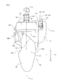
- an air cleaner apparatus 102 has the air cleaner 100, a later-described discharge passage 148, and an air inlet unit 120.
- the air cleaner 100 has an air cleaner case 105.
- the air cleaner case 105 is provided with the air inlet unit 120.
- the air inlet unit 120 has an air inlet port 122 for sucking air and an intake passage 130 extending upward from the air cleaner case 105.
- the intake passage 130 is disposed to the right of the vehicle center line L1.
- the air inlet port 122 of the intake passage 130 is disposed to the right of the right side wall 182 of the storage box 180 and to the left of the right seat frame 28.
- the intake passage 130 is formed so as to extend frontward, or frontward and obliquely upward.
- the intake passage 130 may extend vertically upward, or frontward and obliquely downward.
- vehicle center line means the line that, as viewed in plan, passes through the lateral (widthwise) center of the front wheel 7 and the lateral (widthwise) center of the rear wheel 9 and extends in a longitudinal direction (a front-rear direction).
- a cover 15A having a plurality of slits 17 formed therein is fitted to the muffler 15.
- the slits 17 are formed in a front portion of the cover 15A.
- Each of the slits 17 extends frontward and obliquely downward.
- the slits 17 are aligned one above the other and arranged parallel to each other.
- the center line L2 of the muffler 15 is positioned to the right of the center line L3 of the intake passage 130, when viewed from the rear the motorcycle (vehicle) 1.
- the leftmost end 16 of the muffler 15 is positioned to the right of the center line L3 of the intake passage 130 when viewed from the rear of the vehicle. More preferably, the leftmost end 16 of the muffler 15 is positioned to the right of the rightmost end of the intake passage 130 when viewed from the rear of the vehicle.
- Such a configuration makes it possible to effectively prevent the heat of the muffler 15 from being transmitted to the intake passage 130, which is connected to the air cleaner 100 and the air cleaner 100.
- the term “the center line of the muffler 15" refers to the line that, as viewed in plan, passes through the lateral (widthwise) center of the muffler 15 and extends in a longitudinal direction (a front-rear direction).
- the term “the center line of the intake passage 130” refers to the line that, as viewed in plan, passes through the lateral (widthwise) center of the intake passage 130 and extends in a longitudinal direction (a front/rear direction).
- the vertical lines passing the center lines L1, L2, and L3 are indicated by dash-dotted lines, which are denoted by respective reference characters L1, L2, and L3, in place of the center lines L1, L2, and L3.
- the motorcycle 1 has a rear cushion unit 95 provided between a rear portion of the body frame 20 (typically a rear portion of the left seat frame 26) and a rear portion of the engine unit 40.
- the rear cushion unit 95 is supported by the left seat frame 26 and the transmission case 60.
- the air cleaner 100 is connected to the intake pipe 54 for introducing air to the engine unit 42.
- a connecting portion 43 of the intake pipe 54 for connecting the intake pipe 54 to the engine 42 and a connecting portion 55 of the intake pipe 54 for connecting the intake pipe 54 to the air cleaner 100 are disposed on the vehicle center line L1, as viewed in plan.
- the intake pipe 54 has no or, if any, a little bend in a right/left direction. Therefore, the air-intake characteristics of the engine 42 are good, and the engine performance improves.
- the intake pipe 54 is allowed to extend straight as viewed in plan, so the air-intake resistance can be reduced and the engine performance can be improved.
- the rear fender 80 has an upper portion 82 positioned above the rear wheel 9 and side portions 84A and 84B positioned to the sides of the rear wheel 9.
- the air cleaner 100 forms at least a portion of the upper portion 82 of the rear fender 80. As illustrated in Figs. 6 and 11 , the air cleaner 100 (first case 110) and the rear wheel 9 are disposed so as to overlap each other as viewed from side.
- the front-to-rear length of the right side portion of the air cleaner 100 is set longer than the front-to-rear length of the left side portion thereof.
- the air inlet unit 120 is provided for one of the left and right side portions of the air cleaner 100, with respect to the vehicle center line L1, that has a longer front-to-rear length than the other. In the present embodiment, the air inlet unit 120 is provided on the right side portion (the later-described first case 110) of the air cleaner 100.
- the air cleaner 100 has the air cleaner case 105 including a first case 110 and a second case 140 each having an opening formed therein, and a main filter element 170 for cleaning air.
- the first case 110 and the second case 140 are assembled to each other so that their openings face each other with the main filter element 170 interposed therebetween.
- the main filter element 170 is accommodated in the air cleaner case 105 so that it divides the interior of the air cleaner case 105 into a first chamber 115 (i.e., the internal space of the first case 110) and a second chamber 145 (i.e., the internal space of the second case 140).
- the main filter element 170 may be either a dry-type element (an element not impregnated with oil) or a wet-type element (an element impregnated with oil).
- the phrase "the main filter element 170 divides the interior of the air cleaner case 105 into the first chamber 115 and the second chamber 145" means to include not only a case in which the main filter element 170 forms the entire dividing wall but also a case in which the main filter element 170 forms a portion of the dividing wall.
- the main filter element 170 is fitted to a frame 174.
- the main filter element 170 can be easily fitted into the case 105 together with the frame 174 by respectively fitting engaging portions 176, 176 formed on both end portions of the frame 174 into engaging grooves 106, 106 provided in the air cleaner case 105.
- the main filter element 170 can be easily removed, so the maintenance can be carried out easily.
- the above-described air inlet unit 120 is connected to the first case 110. More specifically, the first case 110 of the air cleaner 100 is provided with the air inlet unit 120 for sucking the air outside the air cleaner case 105 into the first chamber 115. As described previously, the air inlet unit 120 has the air inlet port 122 for sucking air and the intake passage 130 extending upward from the air cleaner case 105 (more specifically from the first case 110). As illustrated in Fig. 13 , the intake passage 130 has an air outlet port 132 for blowing off air into the first chamber 115. As illustrated in Fig. 12 , the air outlet port 132 opens in a direction that intersects a pre-filter element 138. The air outlet port 132 opens in a direction that does not intersect the main filter element 170.
- the pre-filter element 138 comprising a wet-type element (that is, an element impregnated with oil) is disposed in the first chamber 115.
- the pre-filter element 138 is disposed spaced apart from the air outlet port 132 so as to be positioned on the axis line of the air outlet port 132.
- the pre-filter element 138 is disposed so that the blown-off air can hit the pre-filter element 138 but does not pass through the pre-filter element 138.
- the phrase "air passes through the pre-filter element 138" means that the air passes through the pre-filter element 138 without substantially changing its flow direction. Therefore, such an air flow that hits the pre-filter element 138 in the front and leaks from the side faces of the pre-filter element 138, not flowing out from the back face of the pre-filter element 138, does not fit the definition of the phrase "air passes through the pre-filter element" herein.
- the air outlet port 132 be disposed so that the air outlet port 132 faces a central portion of the pre-filter element 138. In other words, it is preferable that the air outlet port 132 be disposed so that the central region of the pre-filter element 138 is positioned on an extension line of the air outlet port 132. In the present embodiment, the air outlet port 132 is disposed between the main filter element 170 and the pre-filter element 138, as illustrated in Fig. 12 . It is preferable that the air outlet port 132 be disposed so that the pre-filter element 138 is positioned on an extension line of at least a portion of the air outlet port 132.
- the air outlet port 132 be disposed so that the pre-filter element 138 is positioned on the extension line of the air outlet port 132.
- the distance between the air outlet port 132 and the pre-filter element 138 be shorter than the distance between the air outlet port 132 and the main filter element 170.
- the surface area of the pre-filter element 138 be greater than the opening area of the air outlet port 132.
- the pre-filter element 138 has a surface area greater than the maximum flow passage cross-sectional area of the intake passage 130. Such a configuration allows the air blown off from the air outlet port 132 to hit the pre-filter element 138 sufficiently because the surface area of the pre-filter element 138 is greater. As a result, the air sucked from outside can be cleaned in good condition by the pre-filter element 138.
- the term "the surface area of the pre-filter element 138" means the area of the surface of the pre-filter element 138 that is exposed to the first chamber 115 and it does not include the area thereof that is in contact with an opposing wall 136.
- the surface area of the main filter element 170 be greater than the surface area of the pre-filter element 138.
- Such a configuration allows large dust to fall off at the pre-filter element 138 and at the same time relatively small dust to be captured in the pre-filter element 138, so that the air sucked from outside can be preliminarily cleaned. Thereafter, the air can be further cleaned in the main filter element 170.
- the term "the surface area of the main filter element 170" means the entire surface area of the main filter element 170 with which the air can be in contact when the air passes from the first chamber 115 to the second chamber 145.
- the first case 110 of the air cleaner 100 has an opposing wall 136 facing the air outlet port 132 and not allowing air to pass therethrough.
- the opposing wall 136 faces the main filter element 170 in the first chamber 115.
- the opposing wall 136 extends in a vertical direction.
- the pre-filter element 138 provided on the opposing wall 136 is disposed so as to extend in a vertical direction. Large dust contained in the air sucked from outside tends to fall off after it strikes the pre-filter element 138. As a result, large dust is not captured by the pre-filter element 138 in a large amount, so the pre-filter element 138 is prevented from clogging.
- the first case 110 of the air cleaner 100 has hook members 134, 134 protruding from the opposing wall 136.
- the pre-filter element 138 is hooked on the hook members 134, 134, whereby the pre-filter element 138 is provided on the opposing wall 136.
- the hook members 134 are fitted in fitting holes 139 formed in the pre-filter element 138 so that the pre-filter element 138 can be mounted onto the opposing wall 136.
- Such a configuration makes the maintenance of the pre-filter element 138 easy.
- the pre-filter element 138 is detachably mounted to the opposing wall 136 by being hooked on the hook members 134, 134, but the method of mounting the pre-filter element 138 to the opposing wall 136 is not particularly limited.
- the pre-filter element 138 may be mounted directly to the opposing wall 136 by using, for example, an adhesive agent.
- a pre-filter element 238 is fitted into and removed from a slot 116 provided in a front end portion of the first case 110.
- the pre-filter element 238 inserted from the slot 116 into the first chamber 115 is prevented from moving in the frontward and rearward directions by a positioning wall 118 formed in the first chamber 115.
- the pre-filter element 238 is prevented from moving in the leftward and rightward directions by a positioning wall 117 formed in the first chamber 115.
- the pre-filter element 138 is provided on a portion of the opposing wall 136 (that is, near the air outlet port 132), but this configuration is merely illustrative.
- the pre-filter element 138 may be provided over the entire surface of the opposing wall 136.
- the pre-filter element 138 may be provided on a wall that makes up the first chamber 115 but does not oppose the main filter element 170 (i.e., a different wall from the opposing wall 136).
- the second case 140 of the air cleaner 100 is provided with the discharge passage 148 for discharging the air within the second chamber 145 out of the air cleaner case 105.
- the discharge passage 148 constitutes a part of the intake pipe 54 that allows the second case 140 of the air cleaner 100 to communicate with the engine 42.
- the air outside the air cleaner case 105 is sucked from the air inlet port 122.
- the sucked air passes through the intake passage 130 and flows from the air outlet port 132 toward a central portion of the pre-filter element 138.
- large dust contained in the air falls off into the first chamber 115.
- a portion of small dust contained in the air is not captured by the pre-filter element 138 and is allowed to flow, while the other portion thereof is captured by the pre-filter element 138.
- the air is cleaned by the pre-filter element 138.
- the air that has been sucked in the first chamber 115 can pass through the main filter element 170 without passing through the pre-filter element 138.
- the sucked air strikes the surface of the pre-filter element 138 and changes its flow direction. Therefore, the increase of the air resistance resulting from the clogging can be prevented.
- the air cleaned by the pre-filter element 138 thereafter passes through the main filter element 170. At this time, the small dust that was not captured by the pre-filter element 138 is captured by the main filter element 170. As a result, the air that has been cleaned in good condition can be supplied to the engine 42.
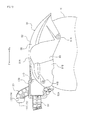
- the air inlet port 122 of the intake passage 130 will be described in detail. As illustrated in Figs. 6 and 7 , at least a portion of the air inlet port 122 of the intake passage 130 faces the right side wall 182 of the storage box 180.
- the intake passage 130 is formed by a duct that cannot contract or expand.
- the length of the intake passage 130 is invariable, and accordingly, the length of the whole intake passage of the engine 42 (that is, the intake passage 130 of the air inlet unit 120, the passage in the air cleaner 100, and the intake pipe 54) is invariable.
- fluctuations in the intake pulse can be suppressed, and the performance of the engine 42 is stabilized.
- the right side wall 182 of the storage box 180 is positioned to the left of the right seat frame 28.
- a recessed portion 190 recessed toward the left is formed in the right side wall 182 of the storage box 180.
- the right side wall 182 of the storage box 180 has a front side wall 184, a rear wall 186 extending leftward from the rear end of the front side wall 184, and a rear side wall 188 extending rearward from the leftmost end of the rear wall 186.
- the recessed portion 190 is defined by at least the rear wall 186 and the rear side wall 188.
- the storage box 180 has the left side wall 192 positioned to the right of the left seat frame 26.
- a recessed portion 200 recessed toward the right is formed in the left side wall 192 of the storage box 180.
- the left side wall 192 of the storage box 180 has a front side wall 194, a rear wall 196 extending rightward from the rear end of the front side wall 194, and a rear side wall 198 extending rearward from the rightmost end of the rear wall 196.
- the recessed portion 200 is defined by at least the rear wall 196 and the rear side wall 198.
- the air inlet port 122 of the intake passage 130 is disposed in the recessed portion 190. That is, as illustrated in Fig. 2 , when viewed from the front of the motorcycle 1, at least a portion of the air inlet port 122 is hidden behind the storage box 180 and cannot be seen. The mud, dust, water, and the like that are splashed up by the front wheel 7 does not easily enter the recessed portion 190. As a result, the air inlet port 122 is prevented from mud, dust, water and the like from entering.
- the air inlet port 122 of the intake passage 130 faces the rear wall 186.
- the air inlet port 122 of the intake passage 130 has a first portion 124 that opens frontward and a second portion 126 that opens (i.e., has an opening) leftward.
- the air inlet port 122 is disposed so that the rightmost end 187 of the rear wall 186 is positioned to the right of the rightmost end 125 of the first portion 124.
- the first portion 124 of the air inlet port 122 faces the rear wall 186 of the right side wall 182.
- the second portion 126 of the air inlet port 122 faces the rear side wall 188 of the right side wall 182.
- the air inlet port 122 of the present embodiment has an L-shape as viewed in plan, but is not limited to having such a shape.
- the air inlet port 122 may have a shape such as to open obliquely leftward and frontward.
- the air inlet port 122 is disposed in the space between the right of the right side wall 182 of the storage box 180 and the left of the right seat frame 28, which has been an unutilized space in the past. Thus, it is not necessary to provide extra space for the air inlet port 122, and it is possible to utilize the existing space effectively. Moreover, the water, mud, dust, and the like that are splashed up from the front wheel 7 are unlikely to enter the air inlet port 122 because at least a portion of the air inlet port 122 is disposed so as to face the right side wall 182 of the storage box 180. As a result, the amount of dust and the like sucked into the air cleaner 100 is reduced, so the performance deterioration of the engine 42 can be prevented effectively.
- At least a portion of the air inlet port 122 is disposed so as to overlap the right seat frame 28 when viewed from the side of the vehicle.
- the right seat frame 28 can prevent mud and dust from entering the air inlet port 122.
- the intake passage 130 connected to the air cleaner 100 is disposed in the space between the right of the right side wall 182 of the storage box 180 and the left of the right seat frame 28.
- another intake passage 210 extending upward from the transmission case 60 can be disposed to the left of the vehicle center line L1 so as not to interfere with the intake passage 130 connected to the air cleaner 100, as illustrated in Figs. 3 and 5 .
- the intake passage 210 can be disposed in the space between the left of the left side wall 192 of the storage box 180 and the right of the left seat frame 26.
- the intake passage 210 is a passage for introducing cooling air to the CVT 62 in the transmission case 60. As illustrated in Fig. 5 , the intake passage 210 has a bellows-shaped duct 214 that can freely contract and expand, and a duct 216 integrally formed with the recessed portion 200 of the left side wall 192 of the storage box.
- An air inlet port 212 that opens leftward is formed at a distal end portion of the duct 216. At least a portion of the air inlet port 212 is disposed in the recessed portion 200.
- the air inlet port 212 is an opening for sucking air. In the present embodiment, the entirety of the air inlet port 212 is disposed in the recessed portion 200.
- the air inlet port 212 opens toward the left from a rear side wall 198 of the left side wall 192. However, like the above-described air inlet port 122 of the intake passage 130, it is sufficient that at least a portion of the air inlet port 212 should face the rear wall 196.
- the mud, dust, water, and the like that are splashed up by the front wheel 7 does not easily enter the recessed portion 200. As a result, the entry of mud, dust, water and the like through the air inlet port 212 into the transmission case 60 can be prevented.
- the air cleaner 100 forms at least a portion of the upper portion 82 of the rear fender 80.
- a portion of the upper portion 82 of the rear fender 80 is formed by the second case 140.
- the first case 110 is disposed at a side of the rear fender 80. By disposing the first case 110 at a side of the rear fender 80 in this way, the second case 140 is ensured to have a large capacity.
- the portion of the rear fender 80 excluding the air cleaner 100 (hereinafter referred to as a "main fender portion 86") and the air cleaner 100 are assembled with each other.
- the main fender portion 86 and the second case 140 of the air cleaner 100 are fastened to each other by a fastener 90A in the upper portion 82 of the rear fender 80.
- the main fender portion 86 and the second case 140 of the air cleaner 100 are fastened to each other by a fastener 90B in the left side portion 84B of the rear fender 80.
- the main fender portion 86 and the first case 110 of the air cleaner 100 are fastened to each other by a fastener 90C in the right side portion 84A of the rear fender 80.
- a fastener 90C in the right side portion 84A of the rear fender 80 examples include commonly-used bolts, screws, and rivets.
- the engine unit 40 and the air cleaner 100 which is a part of the rear fender 80, are fastened to each other by a fastener 92A.
- the main fender portion 86 which is a part of the rear fender 80, and the engine unit 40 are fastened to each other by a fastener 92B.
- the air cleaner 100 and the main fender portion 86 are fixed to each other, and in addition, the air cleaner 100 and the main fender portion 86 are both fixed to the engine unit 40. Therefore, even when the rear fender 80 swings, the air cleaner 100 and the main fender portion 86 can be prevented from chattering and position shifting.
- the leftmost end 142 of the air cleaner 100 (more specifically, the leftmost end 142 of the second case 140) is positioned to the left of the vehicle center line L1.
- the rightmost end 112 of the air cleaner 100 (more specifically, the rightmost end 112 of the first case 110) is positioned to the right of the vehicle center line L1.
- the entire lateral part of a front portion 150 of the rear fender 80 is formed by the air cleaner 100.
- the front portion 150 of the rear fender 80 is the front end face of the air cleaner 100, but the front portion 150 may be a portion that is more rearward than the front end face.
- a boundary 152 between the main fender portion 86 and the air cleaner 100 is inclined with respect to the vehicle center line L1, as viewed in plan.
- the air cleaner 100 is formed so that its front-to-rear length is longer either toward the right or toward the left, as viewed in plan.
- a portion of the boundary 152 between the main fender portion 86 and the air cleaner 100 (more specifically, a region on the right of the laterally central part of the air cleaner 100) is inclined with respect to the vehicle center line L1 as viewed in plan.
- the air cleaner 100 is formed so that its front-to-rear length is longer from the left toward the right. With such a configuration, the air cleaner 100 can be ensured to have a large capacity. When the air cleaner 100 has a large capacity, a large amount of air can be sucked in at one time, so that the engine performance can be improved.
- the air cleaner 100 is formed so that, as viewed in plan, its front-to-rear length is longer from one of the left and right sides on which the footrest 35 is provided toward the other.
- the footrest 35 is provided to the left seat frame 26.
- the air cleaner 100 is formed so that its front-to-rear length is longer from the left toward the right.
- a recessed portion 88 in which a portion of the rear cushion unit 95 (see Fig. 5 ) can be accommodated is formed in a left portion of the rear fender 80.
- the middle position between the leftmost end 142 and the rightmost end 112 of the air cleaner 100 is biased rightward from the vehicle center line L1.
- the middle position of the air cleaner 100 is biased toward the opposite side to one of the left and right sides of the vehicle center line L1 in which the recessed portion 88 of the rear fender 80 is formed.
- the lower end 108 (for example, the bottom face portion of the first chamber 115) of the air cleaner 100 is positioned to be lower than the middle position between an upper end 81 A and a lower end 81B of the rear fender 80.
- the upper end 81 A of the rear fender 80 refers to the vertically uppermost portion of the main fender portion 86 in the rear fender 80 mounted to the engine unit 40.
- the vertically uppermost portion of the main fender portion 86 and the vertically uppermost portion of the air cleaner 100 are located at substantially the same height from the ground.
- the lower end 81 B of the rear fender 80 refers to the vertically lowermost portion of the main fender portion 86 in the rear fender 80 mounted to the engine unit 40.
- the position of the seat 13 can be made low, for example, because the air cleaner 100 is disposed at a low position.
- the lower end 108 of the air cleaner 100 may be a bottom face portion of the second chamber 145, depending on the shape of the air cleaner 100.
- the vertical length of the air cleaner 100 varies from the front toward the rear.
- the maximum vertical length of the air cleaner 100 (for example, the maximum vertical length of the first chamber 115) is shorter than the vertical length of the rear fender 80 at the upper end 81 A position (in other words, the vertical length thereof in the vertical cross section through the position of the upper end 81A).
- an additional spatial margin can be ensured above the air cleaner 100 because the vertical length of the air cleaner 100 is short.
- the position of the seat 13 may be lowered, for example.
- the maximum vertical length of the air cleaner 100 may be the maximum vertical length of the second chamber 145, depending on the shape of the air cleaner 100.
- the air cleaner 100 forms at least a portion of the upper portion 82 of the rear fender 80, and therefore, it is not necessary to dispose an air cleaner separately above the rear fender 80 (for example, over the rear fender 80). Accordingly, there is a greater additional spatial margin than the case in which an air cleaner is disposed above the rear fender, so the capacity of the air cleaner 100 can be made larger. Thereby, the air cleaning performance of the air cleaner 100 can be improved.
- the air cleaner 100 forms at least a portion of the upper portion 82 of the rear fender 80. For this reason, it is not necessary to dispose an air cleaner separately above the rear fender 80. Therefore, there is a greater additional spatial margin than the case in which an air cleaner is disposed above the rear fender 80. As a result, the capacity of the air cleaner 100 can be made larger. Thereby, the air cleaning performance of the air cleaner 100 can be improved.
- the leftmost end 142 of the air cleaner 100 is positioned to the left of the vehicle center line L1, and the rightmost end 122 the air cleaner 100 is positioned to the right of the vehicle center line L1.
- the air cleaner 100 can be ensured to have a large capacity.
- the entire part of the front portion 150 of the rear fender 80 is formed by the air cleaner 100.
- the air cleaner 100 can be ensured to have a large capacity.
- the main fender portion 80 of the rear fender 80 and the air cleaner 100 are assembled with each other, and the boundary 152 between the main fender portion 86 and the air cleaner 100 is inclined with respect to the vehicle center line L1, as viewed in plan.
- the air cleaner 100 can be ensured to have a large capacity.
- the main fender portion 80 of the rear fender 80 and the air cleaner 100 are assembled with each other, and the air cleaner 100 is formed so that, as viewed in plan, its front-to-rear length is longer from one of the left and right sides toward the other. As a result, the air cleaner 100 can be ensured to have a large capacity.
- the air cleaner 100 has the air inlet unit 120 for sucking air.
- the air inlet unit 120 is provided for the first case 110, which is one of the left and right side portions of the air cleaner 100, with respect to the vehicle center line L1, that has a longer front-to-rear length than the other.
- a relatively large space can be formed near the air inlet unit 120 within the air cleaner 100. This can improve the air-intake performance of the air cleaner 100.
- a connecting portion 43 of the intake pipe 54 for connecting the intake pipe 54 to the engine 42 and a connecting portion 55 of the intake pipe 54 for connecting the intake pipe 54 to the air cleaner 100 are disposed on the vehicle center line L1, as viewed in plan.
- the body frame 20 has the main frame 24 extending rearward and obliquely downward from the head pipe 22, and the left and right seat frames 26 and 28 each extending rearward and obliquely upward from the main frame 24.
- the body frame 20 is provided with the passenger footrest 35 supported at a rear portion of the left seat frame 26.
- the air cleaner 100 is formed so that its front-to-rear length is longer from the left side, on which the footrest 35 is provided, toward the right side, as viewed in plan. This serves to avoid the interference between the air cleaner 100 and the footrest 35.
- the front-to-rear length of the air cleaner 100 is longer from the left side, on which the footrest 35 is provided, toward the right. Thereby, the air cleaner 100 can be ensured to have a large capacity.
- the air cleaner 100 has the first case 110 and the second case 140, each having an opening formed therein, and the main filter element 170.
- the first case 110 and the second case 140 are assembled to each other so that their openings face each other with the main filter element 170 interposed therebetween.
- the first case 100 has the air inlet unit 120 for sucking air.
- the intake pipe 54 is connected to the second case 140.
- a portion of the upper portion 82 of the rear fender 80 is formed by the second case 140.
- the first case 110 is disposed beside the rear fender 80. As a result, a large capacity can be ensured for the second case 140 of the air cleaner 100.
- the motorcycle 1 has the rear cushion unit 95 provided between a rear portion of the body frame 20 and a rear portion of the engine unit 40.
- One of the left side portion and the right side portion of the rear fender 80 has the recessed portion 88 in which a portion of the rear cushion unit 95 is accommodated.
- the middle position L4 of the air cleaner 100 that is between the leftmost end 142 and the rightmost end 112 of the air cleaner 100 is biased toward the right side from the vehicle center line L1, i.e., toward the opposite side to the left side, in which the recessed portion 88 of the rear fender 80 is formed.
- the capacity of the air cleaner 100 can be made large without being interfered with the rear cushion unit.
- the air cleaner 100 and the main fender portion 86 of the rear fender 80 are fastened to each other by the fasteners 90A, 90B and 90C, in the upper portion 82, the left side portion 84B, and the right side portion 84A of the rear fender 80.
- the main fender portion 86 can be firmly secured to the air cleaner 100.
- the main fender portion 86 of the rear fender 80 and the air cleaner 100 are assembled with each other.
- the air cleaner 100 and the engine unit 40 are fastened to each other by the fastener 92A.
- the main fender portion 86 and the engine unit 40 are fastened to each other by the fastener 92B.
- chattering and position shifting are unlikely to occur between the main fender portion 86 and the air cleaner 100.
- the rear fender 80 can be firmly secured to the engine unit 40.
- the lower end 80 of the air cleaner 100 is positioned below the middle position of the rear fender 80 that is between the upper end 81 A of the rear fender 80 and the lower end 81 B thereof. Since the air cleaner 100 is disposed at a low position in this way, the position of the seat 13 can be made low, for example.
- the air cleaner 100 has a maximum vertical length shorter than the vertical length of the rear fender 80 at the position of its upper end 81A. Since the vertical length of the air cleaner 100 is short in this way, an additional spatial margin can be ensured above the air cleaner 100. As a result, for example, the position of the seat 13 can be made low.
Abstract
Description
- The present invention relates to a straddle-type vehicle.
The present application claims priority from Japanese Patent Application No.2011-289097, filed on December 28, 2012 - In a straddle-type vehicle having an engine as a driving power source, dust or the like contained in the air supplied to the engine may cause abrasion of the inside of the engine, consequently leading to a shorter engine life span. For this reason, an air cleaner, which is an apparatus for cleaning air, is generally provided on the upstream side of the intake pipe for supplying air to the engine.
- It is known that in order to prevent splashing of water and mud while the straddle-type vehicle is running, a mudguard unit may be provided on the vehicle body cover that covers the body frame. However, in order to improve the mudguard performance for the rear wheel, it is preferable to provide a rear fender that covers the rear wheel and swings along with the rear wheel, as a separate part from the vehicle body cover.
Patent Literature 1 discloses a motorcycle in which an air cleaner is disposed above the rear fender that covers the rear wheel. - [Patent Literature 1]
JP 2006-143082 A - It is difficult to dispose a large capacity air cleaner above the rear fender because the space available there for the air cleaner is limited. As a consequence, when the air cleaner is disposed above the rear fender, the capacity of the air cleaner is small as in the motorcycle described in
Patent Literature 1, so the air cleaning performance required for the air cleaner may not be sufficiently obtained. This problem tends to arise particularly in a straddle-type with a low seat frame (in other words, in a straddle-type vehicle with a low seat position). - The present invention has been accomplished in view of the foregoing and other problems, and it is an object of the invention to provide a straddle-type vehicle equipped with a rear fender that ensures a sufficient capacity for the air cleaner by effectively utilizing limited space and that has excellent air cleaning performance.
- The present invention provides a straddle-type vehicle comprising: a body frame; an engine unit having an engine and having an front end portion swingably supported by the body frame; a rear wheel supported at a rear end portion of the engine unit; a rear fender supported on the engine unit so as to be swingable relative to the body frame along with the rear wheel, the rear fender covering a portion of the rear wheel; an intake pipe for introducing air to the engine; and an air cleaner connected to the intake pipe. The rear fender has an upper portion positioned above the rear wheel, and side portions positioned beside the rear wheel. The air cleaner forms at least a portion of the upper portion of the rear fender.
- In the straddle-type vehicle according to the present invention, the air cleaner forms at least a portion of the upper portion of the rear fender, and therefore, it is not necessary to dispose an air cleaner separately above the rear fender. Therefore, there is a greater additional spatial margin than the case in which an air cleaner is disposed above the rear fender. As a result, the capacity of the air cleaner can be made larger. This can improve the air cleaning performance of the air cleaner.
- In one embodiment of the present invention, a leftmost end of the air cleaner is positioned to the left of the vehicle center line, and a rightmost end the air cleaner is positioned to the right of the vehicle center line.
- Since the air cleaner is formed over a wide region from the left of the vehicle center line to the right in this way, the air cleaner can be ensured to have a large capacity.
- In one embodiment of the present invention, an entire lateral part of a front portion of the rear fender is formed by the air cleaner.
- By forming the entire front portion of the rear fender by the air cleaner in this way, the air cleaner can be ensured to have a large capacity.
- In one embodiment of the present invention, the air cleaner and a portion of the rear fender excluding the air cleaner are assembled with each other, and a boundary between the air cleaner and the portion of the rear fender excluding the air cleaner is inclined with respect to the vehicle center line, as viewed in plan.
- One of the left side portion and the right side portion of the air cleaner may be formed longer along a front-rear direction in this way. As a result, the air cleaner can be ensured to have a large capacity.
- In one embodiment of the present invention, the air cleaner and a portion of the rear fender excluding the air cleaner are assembled with each other, and the air cleaner is formed so that, as viewed in plan, its front-to-rear length is longer from one of left and the right sides toward the other.
- One of the left side portion and the right side portion of the air cleaner may be formed longer along a front-rear direction in this way. As a result, the air cleaner can be ensured to have a large capacity.
- In one embodiment of the present invention, the air cleaner has an air inlet unit for sucking air. The air inlet unit is provided for one of left and right side portions of the air cleaner, with respect to the vehicle center line, that has a longer front-to-rear length than the other.
- Thus, the portion of the air cleaner that is near the air inlet unit has a long front-to-rear length. As a result, a relatively large space can be formed near the air inlet unit within the air cleaner. This can improve the air-intake performance of the air cleaner.
- In one embodiment of the present invention, a connecting portion of the intake pipe for connecting the intake pipe to the engine and a connecting portion thereof for connecting the intake pipe to the air cleaner are disposed on the vehicle center line, as viewed in plan.
- As a result, the intake pipe has no or, if any, a little bend in a right/left direction. Therefore, the air-intake characteristics of the engine are improved, and the engine performance is enhanced.
- In one embodiment of the present invention, the body frame has a main frame extending rearward and obliquely downward from a head pipe, and left and right seat frames each extending rearward and obliquely upward from the main frame. The body frame is provided with a passenger footrest supported at a rear portion of only one of the right and left seat frames. The air cleaner is formed so that, as viewed in plan, its front-to-rear length is longer from one of left and right sides on which the footrest is provided toward the other.
- This serves to avoid the interference between the air cleaner and the footrest. Moreover, since the interference between the air cleaner and the footrest is avoided, the front-to-rear length of the air cleaner is made longer from one of the left and right sides on which the footrest is provided toward the other. Thereby, the air cleaner can be ensured to have a large capacity.
- In one embodiment of the present invention, the air cleaner has a first case and a second case, each having an opening formed therein, and an element. The first case and the second case are assembled to each other so that their openings face each other with the main filter element interposed therebetween. The first case has an air inlet unit for sucking air. The intake pipe is connected to the second case. A portion of the upper portion of the rear fender is formed by the second case.
- This can ensure a large capacity for the second case (i.e., the portion in which the air that has been cleaned by the element exists, what is called a clean side) of the air cleaner.
- In one embodiment of the present invention, the first case is disposed beside the rear fender.
- This can ensure a large capacity for the second case of the air cleaner.
- In one embodiment of the present invention, the straddle-type vehicle further has a rear cushion unit provided between a rear portion of the body frame and a rear portion of the engine unit. One of a left side portion and a right side portion of the rear fender has a recessed portion in which a portion of the rear cushion unit is accommodated. A middle position of the air cleaner that is between a leftmost end and a rightmost end of the air cleaner is biased toward an opposite side to one of left and right sides of the vehicle center line in which the recessed portion of the rear fender is formed.
- Since the air cleaner is biased toward the opposite side to the rear cushion unit, the capacity of the air cleaner can be made large without being interfered with the rear cushion unit.
- In one embodiment of the present invention, the air cleaner and a portion of the rear fender excluding the air cleaner are fastened to each other by a fastener in the upper portion, a left side portion, and a right side portion of the rear fender.
- The air cleaner swings along with the rear fender. However, with the simple structure, the air cleaner can be firmly secured to the portion of the rear fender other than the air cleaner.
- In one embodiment of the present invention, the air cleaner and a portion of the rear fender excluding the air cleaner are assembled with each other. The air cleaner and the engine unit are fastened to each other by a fastener. The engine unit and the portion of the rear fender excluding the air cleaner are fastened to each other by a fastener.
- The air cleaner and the portion of the rear fender excluding the air cleaner swing along with the engine unit. By fastening the air cleaner and the portion of the rear fender excluding the air cleaner to the engine unit, they can be firmly secured to the engine unit. As a result, chattering and position shifting are unlikely to occur between the air cleaner and the portion of the rear fender excluding the air cleaner.
- In one embodiment of the present invention, a lower end of the air cleaner is positioned below a middle position of the rear fender that is between an upper end of the rear fender and a lower end thereof.
- Since the air cleaner is disposed at a low position in this way, the position of the seat can be made low, for example.
- In one embodiment of the present invention, the air cleaner has a maximum vertical length shorter than a vertical length of the rear fender at its upper end position.
- Since the vertical length of the air cleaner is short in this way, an additional spatial margin can be ensured above the air cleaner. As a result, for example, the position of the seat can be lowered.
- As described above, the present invention makes it possible to provide a straddle-type vehicle having a rear fender that ensures a sufficient capacity for an air cleaner by effectively utilizing limited space and that has excellent air cleaning performance.
-
-
Fig. 1 is a right side view illustrating a motorcycle according to one embodiment of the present invention; -
Fig. 2 is a front view illustrating a rear portion of the motorcycle according to one embodiment of the present invention; -
Fig. 3 is a rear view illustrating the rear portion of the motorcycle according to one embodiment of the present invention; -
Fig. 4 is a plan view illustrating the rear portion of the motorcycle according to one embodiment of the present invention; -
Fig. 5 is a left side view illustrating the rear portion of the motorcycle according to one embodiment of the present invention; -
Fig. 6 is a right side view illustrating the rear portion of the motorcycle according to one embodiment of the present invention; -
Fig. 7 is a perspective view illustrating an air cleaner and a storage box according to one embodiment of the present invention; -
Fig. 8 is an internal cross-sectional view illustrating an engine unit according to one embodiment of the present invention; -
Fig. 9 is a plan view illustrating an air cleaner and a rear fender according to one embodiment of the present invention; -
Fig. 10 is a left side view illustrating the air cleaner and the rear fender according to one embodiment of the present invention; -
Fig. 11 is a right side view illustrating the air cleaner and the rear fender according to one embodiment of the present invention; -
Fig. 12 is a horizontal cross-sectional view illustrating the air cleaner according to one embodiment of the present invention; -
Fig. 13 is a cross-sectional view taken along line XIII-XIII inFig. 12 ; and -
Fig. 14 is a horizontal cross-sectional view illustrating an air cleaner according to another embodiment of the present invention. - Hereinbelow, embodiments of the present invention will be described. As illustrated in
Fig. 1 , the straddle-type vehicle according to the present embodiment is ascooter type motorcycle 1. The type of the straddle-type vehicle according to the present invention is, however, not limited to thescooter type motorcycle 1. The straddle-type vehicle according to the present invention may be any other type of motorcycle, such as a moped type motorcycle, an off-road type motorcycle, or an on-road type motorcycle. The straddle-type vehicle according to the present invention is not limited to a motorcycle but may be any other straddle-type vehicle, such as ATV (All Terrain Vehicle). Note that the straddle-type vehicle means a vehicle such that the rider straddles the vehicle when riding. - In the following description, the terms "front," "rear," "left," and "right" respectively refer to front, rear, left, and right as defined based on the perspective of the rider of the
motorcycle 1. Reference characters F, Re, L, and R in the drawings indicate front, rear, left, and right, respectively. - The
motorcycle 1 has avehicle body 5, afront wheel 7, arear wheel 9, and anengine unit 40 for driving therear wheel 9. Thevehicle body 5 has ahandlebar 11, which is operated by the rider, and aseat 13, on which the rider is to be seated. Theengine unit 40 is what is called a unit swing type engine unit that has an engine 42 (seeFig. 8 ). The front end portion of theengine unit 40 is supported by abody frame 20 so that the engine unit can swing about apivot shaft 38, which is a horizontal axis. That is, theengine unit 40 is supported so as to be swingable relative to thebody frame 20. - The
body frame 20 has amain frame 24 extending rearward and obliquely downward from ahead pipe 22, left and right seat frames* 26 (seeFig. 2 ) and 28 extending rearward and obliquely upward from themain frame 24, and a cross-member 30 (seeFig. 2 ) provided between the left and right seat frames 26 and 28. Afront fork 32 is mounted to thehead pipe 22. - A
front wheel 7 is supported at a lower end portion of thefront fork 32. Arear wheel 9 is supported at a rear end portion of theengine unit 40. Arear fender 80 for covering a portion of therear wheel 9 is supported on theengine unit 40. Theair cleaner 80 can swing relative to thebody frame 20, together with therear wheel 9. - As illustrated in
Fig. 4 , themotorcycle 1 has astorage box 180 between the left and right seat frames 26 and 28, which is supported by the cross-member 30. Thestorage box 180 has dimensions such as to accommodate a helmet or the like. An opening is formed in an upper portion of thestorage box 180. The seat 13 (seeFig. 1 ) is configured to be pivotable about the front end portion of theseat 13. When theseat 13 is pivoted so that the rear end portion of theseat 13 moves frontward and obliquely upward, the just-mentioned opening is exposed outside. As illustrated inFig. 5 , thestorage box 180 has aleft side wall 192 positioned to the right of theleft seat frame 26. Also, thestorage box 180 has aright side wall 182 positioned to the left of theright seat frame 28, as illustrated inFig. 6 . - As illustrated in
Figs. 4 and5 , themotorcycle 1 has apassenger footrest 35 supported on a rear portion of the left seat frame 26 (for example, near the upper portion of therear wheel 9 when viewed from side). Of theright seat frame 28 and theleft seat frame 26, only theleft seat frame 26 is provided with thepassenger footrest 35. Thefootrest 35 has a relatively large footrest face 36 (see alsoFig. 4 ). The passenger seated on theseat 13 can put both of his/her feet on thefootrest 35. - It is sufficient that the
footrest 35 is supported on a rear portion of only one of theleft seat frame 26 and theright seat frame 28. Thefootrest 35 may be supported on a rear portion of theright seat frame 28. However, it is more preferable that thefootrest 35 be supported on a rear portion of theleft seat frame 26 because, in that way, the passenger can avoid the heat emitted from amuffler 15. Thus, it is preferable that thefootrest 35 be provided on one of the left and right seat frames that is opposite the one on which themuffler 15 is provided. - The
engine unit 40 is supported by thebody frame 20 below thestorage box 180. As illustrated inFig. 8 , theengine unit 40 has anengine 42, which is one example of an internal combustion engine, and a V-belt type continuously variable transmission (hereinafter referred to as "CVT") 62. Theengine 42 has acrankcase 44, acylinder block 48 extending frontward and obliquely upward from thecrankcase 44, acylinder head 50 connected to a front portion of thecylinder block 48, and acylinder head cover 52 connected to a front portion of thecylinder head 50. In the present specification, the entirety of thecylinder block 48, thecylinder head 50, and thecylinder head cover 52 is collectively called acylinder 46. Thecylinder 46 extends frontward and obliquely upward from thecrankcase 44. Atransmission case 60 is disposed to the left of thecrankcase 44. TheCVT 62 is disposed in thetransmission case 60. - A recessed
portion 53, and an intake port and an exhaust port (not shown) that are connected to the recessedportion 53 are formed in thecylinder head 50. An intake pipe 54 (seeFig. 6 ) is connected to the intake port, and an exhaust pipe 56 (seeFig. 6 ) is connected to the exhaust port. Note that theintake pipe 54 herein is not limited to a single component but may include one comprising a plurality of components combined together. For example, theintake pipe 54 may be formed by a combination of a pipe connected to the intake port, a throttle body connected to the pipe, a duct connected to the throttle body, and so forth. The top face of apiston 59, the inner circumferential wall of thecylinder block 48, and the recessedportion 53 together form acombustion chamber 57. Thepiston 59 is connected to acrankshaft 45 via a connectingrod 58. Thecrank shaft 45 extends leftward and rightward. Thecrank shaft 45 is accommodated in thecrankcase 44. - The
CVT 62 has afirst pulley 64, which is a driving pulley, asecond pulley 66, which is a driven pulley, and a V-belt 68 wrapped around thefirst pulley 64 and thesecond pulley 66. A left end portion of thecrankshaft 45 protrudes to the left from thecrankcase 44. Thefirst pulley 64 is fitted to the left end portion of thecrankshaft 45. Thesecond pulley 66 is fitted to amain shaft 70. Themain shaft 70 is connected to arear wheel shaft 72 via a gear mechanism, which is not shown in the drawings. Note thatFig. 8 depicts the state in which the transmission ratio for a front portion of thefirst pulley 64 and that for a rear portion of thefirst pulley 64 are different from each other. Thesecond pulley 66 has the same configuration. - The
intake pipe 54 is connected to the intake port of thecylinder head 50. Theintake pipe 54 extends rearward from thecylinder head 50. As illustrated inFig. 6 , theintake pipe 54 is disposed above thecylinder 46 and below thestorage box 180. Anair cleaner 100 is connected to a rear portion of theintake pipe 54. - The
exhaust pipe 56 is connected to the exhaust port of thecylinder head 50. Theexhaust pipe 56 extends rearward from thecylinder head 50. Themuffler 15 extending rearward and obliquely upward is connected to a rear end portion of theexhaust pipe 56. - As illustrated in
Fig. 12 , an aircleaner apparatus 102 according to the present embodiment has theair cleaner 100, a later-describeddischarge passage 148, and anair inlet unit 120. Theair cleaner 100 has an aircleaner case 105. Theair cleaner case 105 is provided with theair inlet unit 120. Theair inlet unit 120 has anair inlet port 122 for sucking air and anintake passage 130 extending upward from theair cleaner case 105. As illustrated inFig. 3 , theintake passage 130 is disposed to the right of the vehicle center line L1. Theair inlet port 122 of theintake passage 130 is disposed to the right of theright side wall 182 of thestorage box 180 and to the left of theright seat frame 28. At least a portion of theair inlet port 122 of theintake passage 130 opens toward theright side wall 182 of thestorage box 180. In the present embodiment, theintake passage 130 is formed so as to extend frontward, or frontward and obliquely upward. However, theintake passage 130 may extend vertically upward, or frontward and obliquely downward. - It should be noted that in the present specification, the term "vehicle center line" means the line that, as viewed in plan, passes through the lateral (widthwise) center of the
front wheel 7 and the lateral (widthwise) center of therear wheel 9 and extends in a longitudinal direction (a front-rear direction). - As illustrated in
Fig. 6 , acover 15A having a plurality ofslits 17 formed therein is fitted to themuffler 15. Theslits 17 are formed in a front portion of thecover 15A. Each of theslits 17 extends frontward and obliquely downward. Theslits 17 are aligned one above the other and arranged parallel to each other. When themotorcycle 1 is running, there is a risk the water on the ground may be splashed up by thefront wheel 7, hits thecover 15A, and thereafter scatters upward. However, by providing theslits 17, it is possible to change the direction in which the water splashed up by thefront wheel 7 runs. This effectively prevents the water splashed up by thefront wheel 7 from hitting thecover 15A and entering theair inlet port 122 of theair cleaner apparatus 102. In addition, after having been momentarily captured by theslits 17, the splashed water becomes easy to flow rearward along the surface of thecover 15A. For this reason, thecover 15A can be cooled by this water. Thus, themuffler 15 that has become hot can be cooled indirectly, and also, themuffler 15 can be cooled effectively. - In the present embodiment, as illustrated in
Fig. 3 , the center line L2 of themuffler 15 is positioned to the right of the center line L3 of theintake passage 130, when viewed from the rear the motorcycle (vehicle) 1. Preferably, theleftmost end 16 of themuffler 15 is positioned to the right of the center line L3 of theintake passage 130 when viewed from the rear of the vehicle. More preferably, theleftmost end 16 of themuffler 15 is positioned to the right of the rightmost end of theintake passage 130 when viewed from the rear of the vehicle. Such a configuration makes it possible to effectively prevent the heat of themuffler 15 from being transmitted to theintake passage 130, which is connected to theair cleaner 100 and theair cleaner 100. - In the present specification, the term "the center line of the
muffler 15" refers to the line that, as viewed in plan, passes through the lateral (widthwise) center of themuffler 15 and extends in a longitudinal direction (a front-rear direction). Likewise, In the present specification, the term "the center line of theintake passage 130" refers to the line that, as viewed in plan, passes through the lateral (widthwise) center of theintake passage 130 and extends in a longitudinal direction (a front/rear direction). InFig. 3 , for convenience in illustration, the vertical lines passing the center lines L1, L2, and L3 are indicated by dash-dotted lines, which are denoted by respective reference characters L1, L2, and L3, in place of the center lines L1, L2, and L3. - As illustrated in
Fig. 5 , themotorcycle 1 has arear cushion unit 95 provided between a rear portion of the body frame 20 (typically a rear portion of the left seat frame 26) and a rear portion of theengine unit 40. Therear cushion unit 95 is supported by theleft seat frame 26 and thetransmission case 60. - As illustrated in
Fig. 9 , theair cleaner 100 is connected to theintake pipe 54 for introducing air to theengine unit 42. In the present embodiment, a connectingportion 43 of theintake pipe 54 for connecting theintake pipe 54 to theengine 42 and a connectingportion 55 of theintake pipe 54 for connecting theintake pipe 54 to the air cleaner 100 (second case 140) are disposed on the vehicle center line L1, as viewed in plan. With such a configuration, theintake pipe 54 has no or, if any, a little bend in a right/left direction. Therefore, the air-intake characteristics of theengine 42 are good, and the engine performance improves. In other words, theintake pipe 54 is allowed to extend straight as viewed in plan, so the air-intake resistance can be reduced and the engine performance can be improved. - The
rear fender 80 has anupper portion 82 positioned above therear wheel 9 andside portions rear wheel 9. Theair cleaner 100 forms at least a portion of theupper portion 82 of therear fender 80. As illustrated inFigs. 6 and11 , the air cleaner 100 (first case 110) and therear wheel 9 are disposed so as to overlap each other as viewed from side. - The front-to-rear length of the right side portion of the
air cleaner 100 is set longer than the front-to-rear length of the left side portion thereof. Theair inlet unit 120 is provided for one of the left and right side portions of theair cleaner 100, with respect to the vehicle center line L1, that has a longer front-to-rear length than the other. In the present embodiment, theair inlet unit 120 is provided on the right side portion (the later-described first case 110) of theair cleaner 100. - As illustrated in
Fig. 12 , theair cleaner 100 has theair cleaner case 105 including afirst case 110 and asecond case 140 each having an opening formed therein, and amain filter element 170 for cleaning air. Thefirst case 110 and thesecond case 140 are assembled to each other so that their openings face each other with themain filter element 170 interposed therebetween. Thus, themain filter element 170 is accommodated in theair cleaner case 105 so that it divides the interior of theair cleaner case 105 into a first chamber 115 (i.e., the internal space of the first case 110) and a second chamber 145 (i.e., the internal space of the second case 140). Themain filter element 170 may be either a dry-type element (an element not impregnated with oil) or a wet-type element (an element impregnated with oil). - In the present specification, the phrase "the
main filter element 170 divides the interior of theair cleaner case 105 into thefirst chamber 115 and thesecond chamber 145" means to include not only a case in which themain filter element 170 forms the entire dividing wall but also a case in which themain filter element 170 forms a portion of the dividing wall. - The
main filter element 170 is fitted to aframe 174. Themain filter element 170 can be easily fitted into thecase 105 together with theframe 174 by respectively fitting engagingportions frame 174 into engaginggrooves air cleaner case 105. In addition, in case that themain filter element 170 needs to be replaced, themain filter element 170 can be easily removed, so the maintenance can be carried out easily. - The above-described
air inlet unit 120 is connected to thefirst case 110. More specifically, thefirst case 110 of theair cleaner 100 is provided with theair inlet unit 120 for sucking the air outside theair cleaner case 105 into thefirst chamber 115. As described previously, theair inlet unit 120 has theair inlet port 122 for sucking air and theintake passage 130 extending upward from the air cleaner case 105 (more specifically from the first case 110). As illustrated inFig. 13 , theintake passage 130 has anair outlet port 132 for blowing off air into thefirst chamber 115. As illustrated inFig. 12 , theair outlet port 132 opens in a direction that intersects apre-filter element 138. Theair outlet port 132 opens in a direction that does not intersect themain filter element 170. - As illustrated in
Figs. 12 andFig. 13 , thepre-filter element 138 comprising a wet-type element (that is, an element impregnated with oil) is disposed in thefirst chamber 115. Thepre-filter element 138 is disposed spaced apart from theair outlet port 132 so as to be positioned on the axis line of theair outlet port 132. Thepre-filter element 138 is disposed so that the blown-off air can hit thepre-filter element 138 but does not pass through thepre-filter element 138. - In the present specification, the phrase "air passes through the
pre-filter element 138" means that the air passes through thepre-filter element 138 without substantially changing its flow direction. Therefore, such an air flow that hits thepre-filter element 138 in the front and leaks from the side faces of thepre-filter element 138, not flowing out from the back face of thepre-filter element 138, does not fit the definition of the phrase "air passes through the pre-filter element" herein. - As indicated by the dash-dot-dot line X in
Fig. 13 , it is preferable that theair outlet port 132 be disposed so that theair outlet port 132 faces a central portion of thepre-filter element 138. In other words, it is preferable that theair outlet port 132 be disposed so that the central region of thepre-filter element 138 is positioned on an extension line of theair outlet port 132. In the present embodiment, theair outlet port 132 is disposed between themain filter element 170 and thepre-filter element 138, as illustrated inFig. 12 . It is preferable that theair outlet port 132 be disposed so that thepre-filter element 138 is positioned on an extension line of at least a portion of theair outlet port 132. It is more preferable that theair outlet port 132 be disposed so that thepre-filter element 138 is positioned on the extension line of theair outlet port 132. In addition, it is preferable that the distance between theair outlet port 132 and thepre-filter element 138 be shorter than the distance between theair outlet port 132 and themain filter element 170. Such a configuration allows the air outside the air cleaner to hit thepre-filter element 138 more effectively. - It is preferable that the surface area of the
pre-filter element 138 be greater than the opening area of theair outlet port 132. In addition, it is preferable that thepre-filter element 138 has a surface area greater than the maximum flow passage cross-sectional area of theintake passage 130. Such a configuration allows the air blown off from theair outlet port 132 to hit thepre-filter element 138 sufficiently because the surface area of thepre-filter element 138 is greater. As a result, the air sucked from outside can be cleaned in good condition by thepre-filter element 138. - In the present specification, the term "the surface area of the
pre-filter element 138" means the area of the surface of thepre-filter element 138 that is exposed to thefirst chamber 115 and it does not include the area thereof that is in contact with an opposingwall 136. - It is preferable that the surface area of the
main filter element 170 be greater than the surface area of thepre-filter element 138. Such a configuration allows large dust to fall off at thepre-filter element 138 and at the same time relatively small dust to be captured in thepre-filter element 138, so that the air sucked from outside can be preliminarily cleaned. Thereafter, the air can be further cleaned in themain filter element 170. - In the present specification, the term "the surface area of the
main filter element 170" means the entire surface area of themain filter element 170 with which the air can be in contact when the air passes from thefirst chamber 115 to thesecond chamber 145. - The
first case 110 of theair cleaner 100 has an opposingwall 136 facing theair outlet port 132 and not allowing air to pass therethrough. The opposingwall 136 faces themain filter element 170 in thefirst chamber 115. The opposingwall 136 extends in a vertical direction. Thepre-filter element 138 provided on the opposingwall 136 is disposed so as to extend in a vertical direction. Large dust contained in the air sucked from outside tends to fall off after it strikes thepre-filter element 138. As a result, large dust is not captured by thepre-filter element 138 in a large amount, so thepre-filter element 138 is prevented from clogging. - In the present embodiment, the
first case 110 of theair cleaner 100 hashook members wall 136. Thepre-filter element 138 is hooked on thehook members pre-filter element 138 is provided on the opposingwall 136. As illustrated inFig. 12 , thehook members 134 are fitted infitting holes 139 formed in thepre-filter element 138 so that thepre-filter element 138 can be mounted onto the opposingwall 136. Such a configuration makes the maintenance of thepre-filter element 138 easy. - In the present embodiment, the
pre-filter element 138 is detachably mounted to the opposingwall 136 by being hooked on thehook members pre-filter element 138 to the opposingwall 136 is not particularly limited. For example, thepre-filter element 138 may be mounted directly to the opposingwall 136 by using, for example, an adhesive agent. - In addition, an example of a modified embodiment is shown in
Fig. 14 , in which apre-filter element 238 is fitted into and removed from aslot 116 provided in a front end portion of thefirst case 110. Thepre-filter element 238 inserted from theslot 116 into thefirst chamber 115 is prevented from moving in the frontward and rearward directions by apositioning wall 118 formed in thefirst chamber 115. In addition, thepre-filter element 238 is prevented from moving in the leftward and rightward directions by apositioning wall 117 formed in thefirst chamber 115. When thepre-filter element 238 is fitted in thefirst chamber 115, theslot 116 is closed by a lid or the like so that the outside air does not flow in through theslot 116. - In the present embodiment, the
pre-filter element 138 is provided on a portion of the opposing wall 136 (that is, near the air outlet port 132), but this configuration is merely illustrative. For example, thepre-filter element 138 may be provided over the entire surface of the opposingwall 136. Alternatively, thepre-filter element 138 may be provided on a wall that makes up thefirst chamber 115 but does not oppose the main filter element 170 (i.e., a different wall from the opposing wall 136). - The
second case 140 of theair cleaner 100 is provided with thedischarge passage 148 for discharging the air within thesecond chamber 145 out of theair cleaner case 105. In the present embodiment, thedischarge passage 148 constitutes a part of theintake pipe 54 that allows thesecond case 140 of theair cleaner 100 to communicate with theengine 42. - In the
air cleaner apparatus 102, the air outside theair cleaner case 105 is sucked from theair inlet port 122. The sucked air passes through theintake passage 130 and flows from theair outlet port 132 toward a central portion of thepre-filter element 138. When the sucked air strikes thepre-filter element 138, large dust contained in the air falls off into thefirst chamber 115. On the other hand, a portion of small dust contained in the air is not captured by thepre-filter element 138 and is allowed to flow, while the other portion thereof is captured by thepre-filter element 138. Thus, the air is cleaned by thepre-filter element 138. - Meanwhile, as the small dust is kept captured by the
pre-filter element 138, clogging may occur in thepre-filter element 138 to some degree. However, the air that has been sucked in thefirst chamber 115 can pass through themain filter element 170 without passing through thepre-filter element 138. In addition, the sucked air strikes the surface of thepre-filter element 138 and changes its flow direction. Therefore, the increase of the air resistance resulting from the clogging can be prevented. - The air cleaned by the
pre-filter element 138 thereafter passes through themain filter element 170. At this time, the small dust that was not captured by thepre-filter element 138 is captured by themain filter element 170. As a result, the air that has been cleaned in good condition can be supplied to theengine 42. - Next, the
air inlet port 122 of theintake passage 130 will be described in detail. As illustrated inFigs. 6 and7 , at least a portion of theair inlet port 122 of theintake passage 130 faces theright side wall 182 of thestorage box 180. - In the present embodiment, the
intake passage 130 is formed by a duct that cannot contract or expand. In such a configuration, the length of theintake passage 130 is invariable, and accordingly, the length of the whole intake passage of the engine 42 (that is, theintake passage 130 of theair inlet unit 120, the passage in theair cleaner 100, and the intake pipe 54) is invariable. As a result, fluctuations in the intake pulse can be suppressed, and the performance of theengine 42 is stabilized. - As illustrated in
Figs. 3 and6 , theright side wall 182 of thestorage box 180 is positioned to the left of theright seat frame 28. A recessedportion 190 recessed toward the left is formed in theright side wall 182 of thestorage box 180. Theright side wall 182 of thestorage box 180 has afront side wall 184, arear wall 186 extending leftward from the rear end of thefront side wall 184, and arear side wall 188 extending rearward from the leftmost end of therear wall 186. The recessedportion 190 is defined by at least therear wall 186 and therear side wall 188. - As illustrated in
Figs. 3 and5 , thestorage box 180 has theleft side wall 192 positioned to the right of theleft seat frame 26. A recessedportion 200 recessed toward the right is formed in theleft side wall 192 of thestorage box 180. Theleft side wall 192 of thestorage box 180 has afront side wall 194, arear wall 196 extending rightward from the rear end of thefront side wall 194, and arear side wall 198 extending rearward from the rightmost end of therear wall 196. The recessedportion 200 is defined by at least therear wall 196 and therear side wall 198. - As illustrated in
Fig. 4 , in the present embodiment, at least a portion of theair inlet port 122 of theintake passage 130 is disposed in the recessedportion 190. That is, as illustrated inFig. 2 , when viewed from the front of themotorcycle 1, at least a portion of theair inlet port 122 is hidden behind thestorage box 180 and cannot be seen. The mud, dust, water, and the like that are splashed up by thefront wheel 7 does not easily enter the recessedportion 190. As a result, theair inlet port 122 is prevented from mud, dust, water and the like from entering. - Preferably, at least a portion of the
air inlet port 122 of theintake passage 130 faces therear wall 186. In the present embodiment, as illustrated inFig. 7 , theair inlet port 122 of theintake passage 130 has afirst portion 124 that opens frontward and asecond portion 126 that opens (i.e., has an opening) leftward. As illustrated inFig. 4 , theair inlet port 122 is disposed so that therightmost end 187 of therear wall 186 is positioned to the right of therightmost end 125 of thefirst portion 124. Thefirst portion 124 of theair inlet port 122 faces therear wall 186 of theright side wall 182. Thesecond portion 126 of theair inlet port 122 faces therear side wall 188 of theright side wall 182. By disposing thefirst portion 124 of theair inlet port 122 so as to face therear wall 186 and disposing thesecond portion 126 of theair inlet port 122 so as to face therear side wall 188 in this way, the advantageous effects of disposing theair inlet port 122 within the recessedportion 190 can be obtained without reducing the size of theair inlet port 122. That is, both ensuring sufficient housing space of thestorage box 180 and preventing the entry of dust into theair cleaner 100 can be achieved at the same time. - As illustrated in
Fig. 9 , theair inlet port 122 of the present embodiment has an L-shape as viewed in plan, but is not limited to having such a shape. For example, theair inlet port 122 may have a shape such as to open obliquely leftward and frontward. - The
air inlet port 122 is disposed in the space between the right of theright side wall 182 of thestorage box 180 and the left of theright seat frame 28, which has been an unutilized space in the past. Thus, it is not necessary to provide extra space for theair inlet port 122, and it is possible to utilize the existing space effectively. Moreover, the water, mud, dust, and the like that are splashed up from thefront wheel 7 are unlikely to enter theair inlet port 122 because at least a portion of theair inlet port 122 is disposed so as to face theright side wall 182 of thestorage box 180. As a result, the amount of dust and the like sucked into theair cleaner 100 is reduced, so the performance deterioration of theengine 42 can be prevented effectively. - Preferably, as illustrated in
Fig. 6 , at least a portion of theair inlet port 122 is disposed so as to overlap theright seat frame 28 when viewed from the side of the vehicle. With such a configuration, theright seat frame 28 can prevent mud and dust from entering theair inlet port 122. - In the
motorcycle 1 according to the present embodiment, theintake passage 130 connected to theair cleaner 100 is disposed in the space between the right of theright side wall 182 of thestorage box 180 and the left of theright seat frame 28. For this reason, anotherintake passage 210 extending upward from thetransmission case 60 can be disposed to the left of the vehicle center line L1 so as not to interfere with theintake passage 130 connected to theair cleaner 100, as illustrated inFigs. 3 and5 . In other words, theintake passage 210 can be disposed in the space between the left of theleft side wall 192 of thestorage box 180 and the right of theleft seat frame 26. - The
intake passage 210 is a passage for introducing cooling air to theCVT 62 in thetransmission case 60. As illustrated inFig. 5 , theintake passage 210 has a bellows-shapedduct 214 that can freely contract and expand, and aduct 216 integrally formed with the recessedportion 200 of theleft side wall 192 of the storage box. - An
air inlet port 212 that opens leftward is formed at a distal end portion of theduct 216. At least a portion of theair inlet port 212 is disposed in the recessedportion 200. Theair inlet port 212 is an opening for sucking air. In the present embodiment, the entirety of theair inlet port 212 is disposed in the recessedportion 200. Theair inlet port 212 opens toward the left from arear side wall 198 of theleft side wall 192. However, like the above-describedair inlet port 122 of theintake passage 130, it is sufficient that at least a portion of theair inlet port 212 should face therear wall 196. The mud, dust, water, and the like that are splashed up by thefront wheel 7 does not easily enter the recessedportion 200. As a result, the entry of mud, dust, water and the like through theair inlet port 212 into thetransmission case 60 can be prevented. - Next, the
rear fender 80 will be described in detail. As illustrated inFig. 9 , theair cleaner 100 forms at least a portion of theupper portion 82 of therear fender 80. In the present embodiment, a portion of theupper portion 82 of therear fender 80 is formed by thesecond case 140. Thefirst case 110 is disposed at a side of therear fender 80. By disposing thefirst case 110 at a side of therear fender 80 in this way, thesecond case 140 is ensured to have a large capacity. - The portion of the
rear fender 80 excluding the air cleaner 100 (hereinafter referred to as a "main fender portion 86") and theair cleaner 100 are assembled with each other. As illustrated inFig. 9 , themain fender portion 86 and thesecond case 140 of theair cleaner 100 are fastened to each other by afastener 90A in theupper portion 82 of therear fender 80. As illustrated inFig. 10 , themain fender portion 86 and thesecond case 140 of theair cleaner 100 are fastened to each other by afastener 90B in theleft side portion 84B of therear fender 80. As illustrated inFig. 11 , themain fender portion 86 and thefirst case 110 of theair cleaner 100 are fastened to each other by a fastener 90C in theright side portion 84A of therear fender 80. Examples of thefasteners 90A to 90C in the present embodiment include commonly-used bolts, screws, and rivets. - As illustrated in
Fig. 5 , theengine unit 40 and theair cleaner 100, which is a part of therear fender 80, are fastened to each other by afastener 92A. As illustrated inFig. 6 , themain fender portion 86, which is a part of therear fender 80, and theengine unit 40 are fastened to each other by afastener 92B. Thus, theair cleaner 100 and themain fender portion 86 are fixed to each other, and in addition, theair cleaner 100 and themain fender portion 86 are both fixed to theengine unit 40. Therefore, even when therear fender 80 swings, theair cleaner 100 and themain fender portion 86 can be prevented from chattering and position shifting. - As illustrated in
Fig. 9 , theleftmost end 142 of the air cleaner 100 (more specifically, theleftmost end 142 of the second case 140) is positioned to the left of the vehicle center line L1. Therightmost end 112 of the air cleaner 100 (more specifically, therightmost end 112 of the first case 110) is positioned to the right of the vehicle center line L1. The entire lateral part of afront portion 150 of therear fender 80 is formed by theair cleaner 100. By forming the entire part of thefront portion 150 of therear fender 80 by theair cleaner 100 in this way, the width of theair cleaner 100 can be made large. As a result, theair cleaner 100 can be ensured to have a large capacity. It should be noted that in the present embodiment, thefront portion 150 of therear fender 80 is the front end face of theair cleaner 100, but thefront portion 150 may be a portion that is more rearward than the front end face. - A
boundary 152 between themain fender portion 86 and theair cleaner 100 is inclined with respect to the vehicle center line L1, as viewed in plan. Theair cleaner 100 is formed so that its front-to-rear length is longer either toward the right or toward the left, as viewed in plan. In the present embodiment, a portion of theboundary 152 between themain fender portion 86 and the air cleaner 100 (more specifically, a region on the right of the laterally central part of the air cleaner 100) is inclined with respect to the vehicle center line L1 as viewed in plan. In other words, theair cleaner 100 is formed so that its front-to-rear length is longer from the left toward the right. With such a configuration, theair cleaner 100 can be ensured to have a large capacity. When theair cleaner 100 has a large capacity, a large amount of air can be sucked in at one time, so that the engine performance can be improved. - As illustrated in
Fig. 4 , theair cleaner 100 is formed so that, as viewed in plan, its front-to-rear length is longer from one of the left and right sides on which thefootrest 35 is provided toward the other. In the present embodiment, thefootrest 35 is provided to theleft seat frame 26. Theair cleaner 100 is formed so that its front-to-rear length is longer from the left toward the right. Thus, by making the front-to-rear length of theair cleaner 100 longer while avoiding the interference between theair cleaner 100 and thefootrest 35, theair cleaner 100 can be ensured to have a large capacity. - As illustrated in
Fig. 9 , in the present embodiment, a recessedportion 88 in which a portion of the rear cushion unit 95 (seeFig. 5 ) can be accommodated is formed in a left portion of therear fender 80. The middle position between theleftmost end 142 and therightmost end 112 of the air cleaner 100 (see reference character L4 inFig. 9 ) is biased rightward from the vehicle center line L1. In other words, the middle position of theair cleaner 100 is biased toward the opposite side to one of the left and right sides of the vehicle center line L1 in which the recessedportion 88 of therear fender 80 is formed. - As illustrated in
Fig. 11 , in the present embodiment, the lower end 108 (for example, the bottom face portion of the first chamber 115) of theair cleaner 100 is positioned to be lower than the middle position between anupper end 81 A and alower end 81B of therear fender 80. Theupper end 81 A of therear fender 80 refers to the vertically uppermost portion of themain fender portion 86 in therear fender 80 mounted to theengine unit 40. Typically, the vertically uppermost portion of themain fender portion 86 and the vertically uppermost portion of theair cleaner 100 are located at substantially the same height from the ground. Thelower end 81 B of therear fender 80 refers to the vertically lowermost portion of themain fender portion 86 in therear fender 80 mounted to theengine unit 40. With such a configuration, the position of theseat 13 can be made low, for example, because theair cleaner 100 is disposed at a low position. Note that thelower end 108 of theair cleaner 100 may be a bottom face portion of thesecond chamber 145, depending on the shape of theair cleaner 100. - The vertical length of the
air cleaner 100 varies from the front toward the rear. As illustrated inFig. 11 , in the present embodiment, the maximum vertical length of the air cleaner 100 (for example, the maximum vertical length of the first chamber 115) is shorter than the vertical length of therear fender 80 at theupper end 81 A position (in other words, the vertical length thereof in the vertical cross section through the position of theupper end 81A). With such a configuration, an additional spatial margin can be ensured above theair cleaner 100 because the vertical length of theair cleaner 100 is short. As a result, it becomes possible to dispose other vehicle components above theair cleaner 100, for example. Alternatively, the position of theseat 13 may be lowered, for example. Note that the maximum vertical length of theair cleaner 100 may be the maximum vertical length of thesecond chamber 145, depending on the shape of theair cleaner 100. - The
air cleaner 100 forms at least a portion of theupper portion 82 of therear fender 80, and therefore, it is not necessary to dispose an air cleaner separately above the rear fender 80 (for example, over the rear fender 80). Accordingly, there is a greater additional spatial margin than the case in which an air cleaner is disposed above the rear fender, so the capacity of theair cleaner 100 can be made larger. Thereby, the air cleaning performance of theair cleaner 100 can be improved. - As described above, the
air cleaner 100 according to the present embodiment forms at least a portion of theupper portion 82 of therear fender 80. For this reason, it is not necessary to dispose an air cleaner separately above therear fender 80. Therefore, there is a greater additional spatial margin than the case in which an air cleaner is disposed above therear fender 80. As a result, the capacity of theair cleaner 100 can be made larger. Thereby, the air cleaning performance of theair cleaner 100 can be improved. - In the present embodiment, the
leftmost end 142 of theair cleaner 100 is positioned to the left of the vehicle center line L1, and therightmost end 122 theair cleaner 100 is positioned to the right of the vehicle center line L1. As a result, theair cleaner 100 can be ensured to have a large capacity. - In the present embodiment, the entire part of the
front portion 150 of therear fender 80 is formed by theair cleaner 100. As a result, theair cleaner 100 can be ensured to have a large capacity. - In the present embodiment, the
main fender portion 80 of therear fender 80 and theair cleaner 100 are assembled with each other, and theboundary 152 between themain fender portion 86 and theair cleaner 100 is inclined with respect to the vehicle center line L1, as viewed in plan. As a result, theair cleaner 100 can be ensured to have a large capacity. - In the present embodiment, the
main fender portion 80 of therear fender 80 and theair cleaner 100 are assembled with each other, and theair cleaner 100 is formed so that, as viewed in plan, its front-to-rear length is longer from one of the left and right sides toward the other. As a result, theair cleaner 100 can be ensured to have a large capacity. - In the present embodiment, the
air cleaner 100 has theair inlet unit 120 for sucking air. Theair inlet unit 120 is provided for thefirst case 110, which is one of the left and right side portions of theair cleaner 100, with respect to the vehicle center line L1, that has a longer front-to-rear length than the other. As a result, a relatively large space can be formed near theair inlet unit 120 within theair cleaner 100. This can improve the air-intake performance of theair cleaner 100. - In the present embodiment, a connecting
portion 43 of theintake pipe 54 for connecting theintake pipe 54 to theengine 42 and a connectingportion 55 of theintake pipe 54 for connecting theintake pipe 54 to theair cleaner 100 are disposed on the vehicle center line L1, as viewed in plan. As a result, the air-intake characteristics of the engine are improved, and the engine performance is enhanced. - In the present embodiment, the
body frame 20 has themain frame 24 extending rearward and obliquely downward from thehead pipe 22, and the left and right seat frames 26 and 28 each extending rearward and obliquely upward from themain frame 24. Thebody frame 20 is provided with thepassenger footrest 35 supported at a rear portion of theleft seat frame 26. Theair cleaner 100 is formed so that its front-to-rear length is longer from the left side, on which thefootrest 35 is provided, toward the right side, as viewed in plan. This serves to avoid the interference between theair cleaner 100 and thefootrest 35. In addition, the front-to-rear length of theair cleaner 100 is longer from the left side, on which thefootrest 35 is provided, toward the right. Thereby, theair cleaner 100 can be ensured to have a large capacity. - In the present embodiment, the
air cleaner 100 has thefirst case 110 and thesecond case 140, each having an opening formed therein, and themain filter element 170. Thefirst case 110 and thesecond case 140 are assembled to each other so that their openings face each other with themain filter element 170 interposed therebetween. Thefirst case 100 has theair inlet unit 120 for sucking air. Theintake pipe 54 is connected to thesecond case 140. A portion of theupper portion 82 of therear fender 80 is formed by thesecond case 140. As a result, a large capacity can be ensured for thesecond case 140 of theair cleaner 100. - In the present embodiment, the
first case 110 is disposed beside therear fender 80. As a result, a large capacity can be ensured for thesecond case 140 of theair cleaner 100. - In the present embodiment, the
motorcycle 1 has therear cushion unit 95 provided between a rear portion of thebody frame 20 and a rear portion of theengine unit 40. One of the left side portion and the right side portion of therear fender 80 has the recessedportion 88 in which a portion of therear cushion unit 95 is accommodated. The middle position L4 of theair cleaner 100 that is between theleftmost end 142 and therightmost end 112 of theair cleaner 100 is biased toward the right side from the vehicle center line L1, i.e., toward the opposite side to the left side, in which the recessedportion 88 of therear fender 80 is formed. As a result, the capacity of theair cleaner 100 can be made large without being interfered with the rear cushion unit. - In the present embodiment, the
air cleaner 100 and themain fender portion 86 of therear fender 80 are fastened to each other by thefasteners upper portion 82, theleft side portion 84B, and theright side portion 84A of therear fender 80. As a result, themain fender portion 86 can be firmly secured to theair cleaner 100. - In the present embodiment, the
main fender portion 86 of therear fender 80 and theair cleaner 100 are assembled with each other. Theair cleaner 100 and theengine unit 40 are fastened to each other by thefastener 92A. Themain fender portion 86 and theengine unit 40 are fastened to each other by thefastener 92B. As a result, chattering and position shifting are unlikely to occur between themain fender portion 86 and theair cleaner 100. In addition, therear fender 80 can be firmly secured to theengine unit 40. - In the present embodiment, the
lower end 80 of theair cleaner 100 is positioned below the middle position of therear fender 80 that is between theupper end 81 A of therear fender 80 and thelower end 81 B thereof. Since theair cleaner 100 is disposed at a low position in this way, the position of theseat 13 can be made low, for example. - In the present embodiment, the
air cleaner 100 has a maximum vertical length shorter than the vertical length of therear fender 80 at the position of itsupper end 81A. Since the vertical length of theair cleaner 100 is short in this way, an additional spatial margin can be ensured above theair cleaner 100. As a result, for example, the position of theseat 13 can be made low. -
- 1 -- Motorcycle (straddle-type vehicle)
- 24 -- Main frame
- 26 -- Left seat frame
- 28 -- Right seat frame
- 35 -- Footrest
- 40 -- Engine unit
- 80 -- Rear fender
- 81A -- Upper end
- 81B -- Lower end
- 82 -- Upper portion
- 84A -- Right side portion
- 84B -- Left side portion
- 86 -- Main fender portion
- 88 -- Recessed portion
- 90A, 90B, 90C -- Fastener
- 92A, 92B -- Fastener
- 95 -- Rear cushion unit
- 100 -- Air cleaner
- 110 -- First case
- 120 -- Air inlet unit
- 140 -- Second case
- 152 -- Boundary
- 170 -- Main filter element (dry-type element)
Claims (15)
- A straddle-type vehicle comprising:a body frame;an engine unit having an engine and having an front end portion swingably supported by the body frame;a rear wheel supported at a rear end portion of the engine unit;a rear fender supported on the engine unit so as to be swingable relative to the body frame along with the rear wheel, the rear fender covering a portion of the rear wheel;an intake pipe for introducing air to the engine; andan air cleaner connected to the intake pipe, wherein:the rear fender has an upper portion positioned above the rear wheel, and side portions positioned beside the rear wheel; andthe air cleaner forms at least a portion of the upper portion of the rear fender.
- The straddle-type vehicle according to claim 1, wherein:a leftmost end of the air cleaner is positioned to the left of the vehicle center line; anda rightmost end the air cleaner is positioned to the right of the vehicle center line.
- The straddle-type vehicle according to claim 1, wherein an entire lateral part of a front portion of the rear fender is formed by the air cleaner.
- The straddle-type vehicle according to claim 1, wherein:the air cleaner and a portion of the rear fender excluding the air cleaner are assembled with each other; anda boundary between the air cleaner and the portion of the rear fender excluding the air cleaner is inclined with respect to the vehicle center line, as viewed in plan.
- The straddle-type vehicle according to claim 1, wherein:the air cleaner and a portion of the rear fender excluding the air cleaner are assembled with each other; andthe air cleaner is formed so that, as viewed in plan, its front-to-rear length is longer from one of left and right sides toward the other.
- The straddle-type vehicle according to claim 5, wherein:the air cleaner has an air inlet unit for sucking air; andthe air inlet unit is provided for one of left and right side portions of the air cleaner, with respect to the vehicle center line, that has a longer front-to-rear length than the other.
- The straddle-type vehicle according to claim 1, wherein a connecting portion of the intake pipe for connecting the intake pipe to the engine and a connecting portion thereof for connecting the intake pipe to the air cleaner are disposed on the vehicle center line, as viewed in plan.
- The straddle-type vehicle according to claim 1, wherein:the body frame has a main frame extending rearward and obliquely downward from a head pipe, and right and left seat frames each extending rearward and obliquely upward from the main frame; and further comprisinga passenger footrest supported at a rear portion of only one of the right and left seat frames; and whereinthe air cleaner is formed so that its front-to-rear length is longer from one of left and right sides on which the footrest is provided toward the other.
- The straddle-type vehicle according to claim 1, wherein:the air cleaner has a first case and a second case, each having an opening formed therein, and an element;the first case and the second case are assembled to each other so that their openings face each other with the main filter element interposed therebetween;the first case has an air inlet unit for sucking air;the intake pipe is connected to the second case; anda portion of the upper portion of the rear fender is formed by the second case.
- The straddle-type vehicle according to claim 9, wherein the first case is disposed beside the rear fender.
- The straddle-type vehicle according to claim 1, further comprising:a rear cushion unit provided between a rear portion of the body frame and a rear portion of the engine unit; and whereinone of a left side portion and a right side portion of the rear fender has a recessed portion in which a portion of the rear cushion unit is accommodated; anda middle position of the air cleaner that is between a leftmost end and a rightmost end of the air cleaner is biased toward an opposite side to one of left and right sides of the vehicle center line in which the recessed portion of the rear fender is formed.
- The straddle-type vehicle according to claim 1, wherein the air cleaner and a portion of the rear fender excluding the air cleaner are fastened to each other by a fastener in the upper portion, a left side portion, and a right side portion of the rear fender.
- The straddle-type vehicle according to claim 1, wherein:the air cleaner and a portion of the rear fender excluding the air cleaner are assembled with each other;the air cleaner and the engine unit are fastened to each other by a fastener; andthe engine unit and the portion of the rear fender excluding the air cleaner are fastened to each other by a fastener.
- The straddle-type vehicle according to claim 1, wherein a lower end of the air cleaner is positioned below a middle position of the rear fender that is between an upper end of the rear fender and a lower end thereof.
- The straddle-type vehicle according to claim 1, wherein the air cleaner has a maximum vertical length shorter than a vertical length of the rear fender at its upper end position.
Applications Claiming Priority (1)
| Application Number | Priority Date | Filing Date | Title |
|---|---|---|---|
| JP2011289097A JP2013136342A (en) | 2011-12-28 | 2011-12-28 | Straddle-type vehicle |
Publications (2)
| Publication Number | Publication Date |
|---|---|
| EP2610155A1 true EP2610155A1 (en) | 2013-07-03 |
| EP2610155B1 EP2610155B1 (en) | 2014-12-10 |
Family
ID=47142961
Family Applications (1)
| Application Number | Title | Priority Date | Filing Date |
|---|---|---|---|
| EP20120190474 Active EP2610155B1 (en) | 2011-12-28 | 2012-10-30 | Straddle-type vehicle |
Country Status (4)
| Country | Link |
|---|---|
| EP (1) | EP2610155B1 (en) |
| JP (1) | JP2013136342A (en) |
| CN (1) | CN103182929B (en) |
| ES (1) | ES2530173T3 (en) |
Cited By (2)
| Publication number | Priority date | Publication date | Assignee | Title |
|---|---|---|---|---|
| EP2949564A1 (en) * | 2014-05-30 | 2015-12-02 | Yamaha Hatsudoki Kabushiki Kaisha | Vehicle |
| CN109578184A (en) * | 2018-09-05 | 2019-04-05 | 广东恒勃滤清器有限公司 | A kind of air cleaner for motorcycle |
Families Citing this family (4)
| Publication number | Priority date | Publication date | Assignee | Title |
|---|---|---|---|---|
| JP5852071B2 (en) * | 2013-09-26 | 2016-02-03 | 本田技研工業株式会社 | Air intake structure for saddle-ride type vehicles |
| JP5865323B2 (en) * | 2013-09-30 | 2016-02-17 | 本田技研工業株式会社 | Saddle riding |
| US10131396B2 (en) | 2013-09-30 | 2018-11-20 | Honda Motor Co., Ltd. | Saddled vehicle |
| JP6924332B2 (en) * | 2018-07-26 | 2021-08-25 | 本田技研工業株式会社 | Air cleaner support structure for saddle-mounted vehicles |
Citations (5)
| Publication number | Priority date | Publication date | Assignee | Title |
|---|---|---|---|---|
| US4280582A (en) * | 1976-11-01 | 1981-07-28 | Honda Giken Kogyo Kabushiki Kaisha | Vehicle frame arrangement in motorized two-wheeled vehicle |
| US4402379A (en) * | 1980-06-30 | 1983-09-06 | Honda Giken Kogyo Kabushiki Kaisha | Air cleaner system for motorcycles |
| US6283242B1 (en) * | 1998-09-11 | 2001-09-04 | Honda Giken Kogyo Kabushiki Kaisha | Structure of air cleaner of motorcycle |
| JP2002235535A (en) * | 2001-02-09 | 2002-08-23 | Honda Motor Co Ltd | Exhaust emission control device for scooter type vehicle |
| JP2006143082A (en) | 2004-11-22 | 2006-06-08 | Yamaha Motor Co Ltd | Saddle riding type vehicle |
-
2011
- 2011-12-28 JP JP2011289097A patent/JP2013136342A/en active Pending
-
2012
- 2012-10-30 CN CN201210424571.9A patent/CN103182929B/en active Active
- 2012-10-30 EP EP20120190474 patent/EP2610155B1/en active Active
- 2012-10-30 ES ES12190474.2T patent/ES2530173T3/en active Active
Patent Citations (6)
| Publication number | Priority date | Publication date | Assignee | Title |
|---|---|---|---|---|
| US4280582A (en) * | 1976-11-01 | 1981-07-28 | Honda Giken Kogyo Kabushiki Kaisha | Vehicle frame arrangement in motorized two-wheeled vehicle |
| US4402379A (en) * | 1980-06-30 | 1983-09-06 | Honda Giken Kogyo Kabushiki Kaisha | Air cleaner system for motorcycles |
| US6283242B1 (en) * | 1998-09-11 | 2001-09-04 | Honda Giken Kogyo Kabushiki Kaisha | Structure of air cleaner of motorcycle |
| JP2002235535A (en) * | 2001-02-09 | 2002-08-23 | Honda Motor Co Ltd | Exhaust emission control device for scooter type vehicle |
| JP2006143082A (en) | 2004-11-22 | 2006-06-08 | Yamaha Motor Co Ltd | Saddle riding type vehicle |
| US20060124379A1 (en) * | 2004-11-22 | 2006-06-15 | Masaru Ohira | System for accessing an air box in a straddle type vehicle |
Cited By (5)
| Publication number | Priority date | Publication date | Assignee | Title |
|---|---|---|---|---|
| EP2949564A1 (en) * | 2014-05-30 | 2015-12-02 | Yamaha Hatsudoki Kabushiki Kaisha | Vehicle |
| CN105270532A (en) * | 2014-05-30 | 2016-01-27 | 雅马哈发动机株式会社 | Vehicle |
| CN105270532B (en) * | 2014-05-30 | 2018-09-25 | 雅马哈发动机株式会社 | Vehicle |
| CN109578184A (en) * | 2018-09-05 | 2019-04-05 | 广东恒勃滤清器有限公司 | A kind of air cleaner for motorcycle |
| CN109578184B (en) * | 2018-09-05 | 2023-08-29 | 广东恒勃滤清器有限公司 | motorcycle air filter |
Also Published As
| Publication number | Publication date |
|---|---|
| JP2013136342A (en) | 2013-07-11 |
| CN103182929A (en) | 2013-07-03 |
| EP2610155B1 (en) | 2014-12-10 |
| CN103182929B (en) | 2016-03-16 |
| ES2530173T3 (en) | 2015-02-26 |
Similar Documents
| Publication | Publication Date | Title |
|---|---|---|
| EP2610155B1 (en) | Straddle-type vehicle | |
| US7975792B2 (en) | Straddle type vehicle | |
| JP6055751B2 (en) | Intake device for saddle-ride type vehicles | |
| US7395800B2 (en) | Four-cycle engine and motorcycle comprising four-cycle engine | |
| EP2610476B1 (en) | Air cleaner apparatus and straddle-type vehicle equipped with the apparatus | |
| JP2009228708A (en) | Cooling structure for transmission | |
| EP2289787B1 (en) | Saddle-ride type vehicle | |
| US20090049813A1 (en) | Engine Unit and Straddle-Type Vehicle | |
| JP5486872B2 (en) | Power unit cooling system | |
| EP2610156B1 (en) | Straddle-type vehicle | |
| JP4802727B2 (en) | Rough terrain vehicle | |
| JP3142128U (en) | Breather structure of internal combustion engine and vehicle equipped with the same | |
| EP2295833B1 (en) | Engine unit, and a two-wheeled motor vehicle having the same | |
| JP2007113565A (en) | Breather device for motorcycle | |
| JP4901619B2 (en) | Breather device for internal combustion engine | |
| JP2011031872A (en) | Motorcycle | |
| CN103216302B (en) | Internal combustion engine and possess its riding vehicle | |
| JP3168137U (en) | Transmission cooling structure | |
| JP4853213B2 (en) | Saddle-type rough terrain vehicle | |
| JP7216128B2 (en) | Intake structure | |
| JP6485087B2 (en) | Cooling structure for continuously variable transmission | |
| JP3150483U (en) | Motorcycle | |
| EP2272740A1 (en) | Motorcycle | |
| JP2008185055A (en) | Motorcycle | |
| JP7453012B2 (en) | air-cooled internal combustion engine |
Legal Events
| Date | Code | Title | Description |
|---|---|---|---|
| PUAI | Public reference made under article 153(3) epc to a published international application that has entered the european phase |
Free format text: ORIGINAL CODE: 0009012 |
|
| AK | Designated contracting states |
Kind code of ref document: A1 Designated state(s): AL AT BE BG CH CY CZ DE DK EE ES FI FR GB GR HR HU IE IS IT LI LT LU LV MC MK MT NL NO PL PT RO RS SE SI SK SM TR |
|
| AX | Request for extension of the european patent |
Extension state: BA ME |
|
| 17P | Request for examination filed |
Effective date: 20131204 |
|
| RBV | Designated contracting states (corrected) |
Designated state(s): AL AT BE BG CH CY CZ DE DK EE ES FI FR GB GR HR HU IE IS IT LI LT LU LV MC MK MT NL NO PL PT RO RS SE SI SK SM TR |
|
| REG | Reference to a national code |
Ref country code: DE Ref legal event code: R079 Ref document number: 602012004223 Country of ref document: DE Free format text: PREVIOUS MAIN CLASS: B62K0011040000 Ipc: B62J0015000000 |
|
| GRAP | Despatch of communication of intention to grant a patent |
Free format text: ORIGINAL CODE: EPIDOSNIGR1 |
|
| RIC1 | Information provided on ipc code assigned before grant |
Ipc: B62J 15/00 20060101AFI20140602BHEP |
|
| INTG | Intention to grant announced |
Effective date: 20140626 |
|
| GRAS | Grant fee paid |
Free format text: ORIGINAL CODE: EPIDOSNIGR3 |
|
| GRAA | (expected) grant |
Free format text: ORIGINAL CODE: 0009210 |
|
| AK | Designated contracting states |
Kind code of ref document: B1 Designated state(s): AL AT BE BG CH CY CZ DE DK EE ES FI FR GB GR HR HU IE IS IT LI LT LU LV MC MK MT NL NO PL PT RO RS SE SI SK SM TR |
|
| REG | Reference to a national code |
Ref country code: GB Ref legal event code: FG4D |
|
| REG | Reference to a national code |
Ref country code: CH Ref legal event code: EP |
|
| REG | Reference to a national code |
Ref country code: IE Ref legal event code: FG4D |
|
| REG | Reference to a national code |
Ref country code: AT Ref legal event code: REF Ref document number: 700503 Country of ref document: AT Kind code of ref document: T Effective date: 20150115 |
|
| REG | Reference to a national code |
Ref country code: DE Ref legal event code: R096 Ref document number: 602012004223 Country of ref document: DE Effective date: 20150122 |
|
| REG | Reference to a national code |
Ref country code: ES Ref legal event code: FG2A Ref document number: 2530173 Country of ref document: ES Kind code of ref document: T3 Effective date: 20150226 |
|
| REG | Reference to a national code |
Ref country code: AT Ref legal event code: MK05 Ref document number: 700503 Country of ref document: AT Kind code of ref document: T Effective date: 20141210 Ref country code: NL Ref legal event code: VDEP Effective date: 20141210 |
|
| REG | Reference to a national code |
Ref country code: NL Ref legal event code: VDEP Effective date: 20141210 |
|
| PG25 | Lapsed in a contracting state [announced via postgrant information from national office to epo] |
Ref country code: FI Free format text: LAPSE BECAUSE OF FAILURE TO SUBMIT A TRANSLATION OF THE DESCRIPTION OR TO PAY THE FEE WITHIN THE PRESCRIBED TIME-LIMIT Effective date: 20141210 Ref country code: NO Free format text: LAPSE BECAUSE OF FAILURE TO SUBMIT A TRANSLATION OF THE DESCRIPTION OR TO PAY THE FEE WITHIN THE PRESCRIBED TIME-LIMIT Effective date: 20150310 Ref country code: LT Free format text: LAPSE BECAUSE OF FAILURE TO SUBMIT A TRANSLATION OF THE DESCRIPTION OR TO PAY THE FEE WITHIN THE PRESCRIBED TIME-LIMIT Effective date: 20141210 |
|
| REG | Reference to a national code |
Ref country code: LT Ref legal event code: MG4D |
|
| PG25 | Lapsed in a contracting state [announced via postgrant information from national office to epo] |
Ref country code: SE Free format text: LAPSE BECAUSE OF FAILURE TO SUBMIT A TRANSLATION OF THE DESCRIPTION OR TO PAY THE FEE WITHIN THE PRESCRIBED TIME-LIMIT Effective date: 20141210 Ref country code: LV Free format text: LAPSE BECAUSE OF FAILURE TO SUBMIT A TRANSLATION OF THE DESCRIPTION OR TO PAY THE FEE WITHIN THE PRESCRIBED TIME-LIMIT Effective date: 20141210 Ref country code: GR Free format text: LAPSE BECAUSE OF FAILURE TO SUBMIT A TRANSLATION OF THE DESCRIPTION OR TO PAY THE FEE WITHIN THE PRESCRIBED TIME-LIMIT Effective date: 20150311 Ref country code: AT Free format text: LAPSE BECAUSE OF FAILURE TO SUBMIT A TRANSLATION OF THE DESCRIPTION OR TO PAY THE FEE WITHIN THE PRESCRIBED TIME-LIMIT Effective date: 20141210 Ref country code: RS Free format text: LAPSE BECAUSE OF FAILURE TO SUBMIT A TRANSLATION OF THE DESCRIPTION OR TO PAY THE FEE WITHIN THE PRESCRIBED TIME-LIMIT Effective date: 20141210 Ref country code: HR Free format text: LAPSE BECAUSE OF FAILURE TO SUBMIT A TRANSLATION OF THE DESCRIPTION OR TO PAY THE FEE WITHIN THE PRESCRIBED TIME-LIMIT Effective date: 20141210 |
|
| PG25 | Lapsed in a contracting state [announced via postgrant information from national office to epo] |
Ref country code: NL Free format text: LAPSE BECAUSE OF FAILURE TO SUBMIT A TRANSLATION OF THE DESCRIPTION OR TO PAY THE FEE WITHIN THE PRESCRIBED TIME-LIMIT Effective date: 20141210 |
|
| PG25 | Lapsed in a contracting state [announced via postgrant information from national office to epo] |
Ref country code: CZ Free format text: LAPSE BECAUSE OF FAILURE TO SUBMIT A TRANSLATION OF THE DESCRIPTION OR TO PAY THE FEE WITHIN THE PRESCRIBED TIME-LIMIT Effective date: 20141210 Ref country code: EE Free format text: LAPSE BECAUSE OF FAILURE TO SUBMIT A TRANSLATION OF THE DESCRIPTION OR TO PAY THE FEE WITHIN THE PRESCRIBED TIME-LIMIT Effective date: 20141210 Ref country code: PT Free format text: LAPSE BECAUSE OF FAILURE TO SUBMIT A TRANSLATION OF THE DESCRIPTION OR TO PAY THE FEE WITHIN THE PRESCRIBED TIME-LIMIT Effective date: 20150410 Ref country code: SK Free format text: LAPSE BECAUSE OF FAILURE TO SUBMIT A TRANSLATION OF THE DESCRIPTION OR TO PAY THE FEE WITHIN THE PRESCRIBED TIME-LIMIT Effective date: 20141210 Ref country code: RO Free format text: LAPSE BECAUSE OF FAILURE TO SUBMIT A TRANSLATION OF THE DESCRIPTION OR TO PAY THE FEE WITHIN THE PRESCRIBED TIME-LIMIT Effective date: 20141210 |
|
| PG25 | Lapsed in a contracting state [announced via postgrant information from national office to epo] |
Ref country code: PL Free format text: LAPSE BECAUSE OF FAILURE TO SUBMIT A TRANSLATION OF THE DESCRIPTION OR TO PAY THE FEE WITHIN THE PRESCRIBED TIME-LIMIT Effective date: 20141210 Ref country code: IS Free format text: LAPSE BECAUSE OF FAILURE TO SUBMIT A TRANSLATION OF THE DESCRIPTION OR TO PAY THE FEE WITHIN THE PRESCRIBED TIME-LIMIT Effective date: 20150410 |
|
| REG | Reference to a national code |
Ref country code: DE Ref legal event code: R097 Ref document number: 602012004223 Country of ref document: DE |
|
| PLBE | No opposition filed within time limit |
Free format text: ORIGINAL CODE: 0009261 |
|
| STAA | Information on the status of an ep patent application or granted ep patent |
Free format text: STATUS: NO OPPOSITION FILED WITHIN TIME LIMIT |
|
| REG | Reference to a national code |
Ref country code: FR Ref legal event code: PLFP Year of fee payment: 4 |
|
| PG25 | Lapsed in a contracting state [announced via postgrant information from national office to epo] |
Ref country code: DK Free format text: LAPSE BECAUSE OF FAILURE TO SUBMIT A TRANSLATION OF THE DESCRIPTION OR TO PAY THE FEE WITHIN THE PRESCRIBED TIME-LIMIT Effective date: 20141210 |
|
| 26N | No opposition filed |
Effective date: 20150911 |
|
| PG25 | Lapsed in a contracting state [announced via postgrant information from national office to epo] |
Ref country code: SI Free format text: LAPSE BECAUSE OF FAILURE TO SUBMIT A TRANSLATION OF THE DESCRIPTION OR TO PAY THE FEE WITHIN THE PRESCRIBED TIME-LIMIT Effective date: 20141210 |
|
| PG25 | Lapsed in a contracting state [announced via postgrant information from national office to epo] |
Ref country code: LU Free format text: LAPSE BECAUSE OF FAILURE TO SUBMIT A TRANSLATION OF THE DESCRIPTION OR TO PAY THE FEE WITHIN THE PRESCRIBED TIME-LIMIT Effective date: 20151030 Ref country code: BE Free format text: LAPSE BECAUSE OF FAILURE TO SUBMIT A TRANSLATION OF THE DESCRIPTION OR TO PAY THE FEE WITHIN THE PRESCRIBED TIME-LIMIT Effective date: 20141210 |
|
| REG | Reference to a national code |
Ref country code: CH Ref legal event code: PL |
|
| PG25 | Lapsed in a contracting state [announced via postgrant information from national office to epo] |
Ref country code: MC Free format text: LAPSE BECAUSE OF FAILURE TO SUBMIT A TRANSLATION OF THE DESCRIPTION OR TO PAY THE FEE WITHIN THE PRESCRIBED TIME-LIMIT Effective date: 20141210 |
|
| REG | Reference to a national code |
Ref country code: IE Ref legal event code: MM4A |
|
| PG25 | Lapsed in a contracting state [announced via postgrant information from national office to epo] |
Ref country code: LI Free format text: LAPSE BECAUSE OF NON-PAYMENT OF DUE FEES Effective date: 20151031 Ref country code: CH Free format text: LAPSE BECAUSE OF NON-PAYMENT OF DUE FEES Effective date: 20151031 |
|
| REG | Reference to a national code |
Ref country code: FR Ref legal event code: PLFP Year of fee payment: 5 |
|
| PG25 | Lapsed in a contracting state [announced via postgrant information from national office to epo] |
Ref country code: IE Free format text: LAPSE BECAUSE OF NON-PAYMENT OF DUE FEES Effective date: 20151030 |
|
| PG25 | Lapsed in a contracting state [announced via postgrant information from national office to epo] |
Ref country code: BG Free format text: LAPSE BECAUSE OF FAILURE TO SUBMIT A TRANSLATION OF THE DESCRIPTION OR TO PAY THE FEE WITHIN THE PRESCRIBED TIME-LIMIT Effective date: 20141210 Ref country code: SM Free format text: LAPSE BECAUSE OF FAILURE TO SUBMIT A TRANSLATION OF THE DESCRIPTION OR TO PAY THE FEE WITHIN THE PRESCRIBED TIME-LIMIT Effective date: 20141210 Ref country code: HU Free format text: LAPSE BECAUSE OF FAILURE TO SUBMIT A TRANSLATION OF THE DESCRIPTION OR TO PAY THE FEE WITHIN THE PRESCRIBED TIME-LIMIT; INVALID AB INITIO Effective date: 20121030 |
|
| GBPC | Gb: european patent ceased through non-payment of renewal fee |
Effective date: 20161030 |
|
| PG25 | Lapsed in a contracting state [announced via postgrant information from national office to epo] |
Ref country code: CY Free format text: LAPSE BECAUSE OF FAILURE TO SUBMIT A TRANSLATION OF THE DESCRIPTION OR TO PAY THE FEE WITHIN THE PRESCRIBED TIME-LIMIT Effective date: 20141210 |
|
| PG25 | Lapsed in a contracting state [announced via postgrant information from national office to epo] |
Ref country code: GB Free format text: LAPSE BECAUSE OF NON-PAYMENT OF DUE FEES Effective date: 20161030 |
|
| PG25 | Lapsed in a contracting state [announced via postgrant information from national office to epo] |
Ref country code: MT Free format text: LAPSE BECAUSE OF FAILURE TO SUBMIT A TRANSLATION OF THE DESCRIPTION OR TO PAY THE FEE WITHIN THE PRESCRIBED TIME-LIMIT Effective date: 20141210 |
|
| REG | Reference to a national code |
Ref country code: FR Ref legal event code: PLFP Year of fee payment: 6 |
|
| PG25 | Lapsed in a contracting state [announced via postgrant information from national office to epo] |
Ref country code: MK Free format text: LAPSE BECAUSE OF FAILURE TO SUBMIT A TRANSLATION OF THE DESCRIPTION OR TO PAY THE FEE WITHIN THE PRESCRIBED TIME-LIMIT Effective date: 20141210 Ref country code: TR Free format text: LAPSE BECAUSE OF FAILURE TO SUBMIT A TRANSLATION OF THE DESCRIPTION OR TO PAY THE FEE WITHIN THE PRESCRIBED TIME-LIMIT Effective date: 20141210 |
|
| REG | Reference to a national code |
Ref country code: FR Ref legal event code: PLFP Year of fee payment: 7 |
|
| PG25 | Lapsed in a contracting state [announced via postgrant information from national office to epo] |
Ref country code: AL Free format text: LAPSE BECAUSE OF FAILURE TO SUBMIT A TRANSLATION OF THE DESCRIPTION OR TO PAY THE FEE WITHIN THE PRESCRIBED TIME-LIMIT Effective date: 20141210 |
|
| P01 | Opt-out of the competence of the unified patent court (upc) registered |
Effective date: 20230527 |
|
| PGFP | Annual fee paid to national office [announced via postgrant information from national office to epo] |
Ref country code: ES Payment date: 20231227 Year of fee payment: 12 |
|
| PGFP | Annual fee paid to national office [announced via postgrant information from national office to epo] |
Ref country code: IT Payment date: 20231026 Year of fee payment: 12 Ref country code: FR Payment date: 20231025 Year of fee payment: 12 Ref country code: DE Payment date: 20231020 Year of fee payment: 12 |