EP2610039B1 - Haarschneidemaschine mit einrückbarem Rad - Google Patents
Haarschneidemaschine mit einrückbarem Rad Download PDFInfo
- Publication number
- EP2610039B1 EP2610039B1 EP12198716.8A EP12198716A EP2610039B1 EP 2610039 B1 EP2610039 B1 EP 2610039B1 EP 12198716 A EP12198716 A EP 12198716A EP 2610039 B1 EP2610039 B1 EP 2610039B1
- Authority
- EP
- European Patent Office
- Prior art keywords
- adjustment
- hair clippers
- adjustment mechanism
- incorporating
- comb
- Prior art date
- Legal status (The legal status is an assumption and is not a legal conclusion. Google has not performed a legal analysis and makes no representation as to the accuracy of the status listed.)
- Active
Links
Images



Classifications
-
- B—PERFORMING OPERATIONS; TRANSPORTING
- B26—HAND CUTTING TOOLS; CUTTING; SEVERING
- B26B—HAND-HELD CUTTING TOOLS NOT OTHERWISE PROVIDED FOR
- B26B19/00—Clippers or shavers operating with a plurality of cutting edges, e.g. hair clippers, dry shavers
- B26B19/20—Clippers or shavers operating with a plurality of cutting edges, e.g. hair clippers, dry shavers with provision for shearing hair of preselected or variable length
Definitions
- the present invention relates to the technical field of hair clippers or beard, more particularly the field of electric hair clippers or beards.
- Such mowers generally comprise a housing on one end of which is arranged a cutting head which is composed of two cutting blades driven by a relative movement of alternating oscillations provided by an electric motor.
- An electric power supply of the wired motor can be envisaged as well as a battery power supply.
- the mower may include an accessory, often in the form of a comb, adapted to the housing and / or the cutting head to define a bearing surface on the scalp of the user.
- the length of the cut hair thus corresponds to the absolute distance between this support surface and the cutting head, this distance can be modified to give several possible lengths by accessory change when it is defined by the dimensions of the accessory, or by moving a part or all of the accessory mounted on housing / cutting head.
- WO98 / 25734 discloses a hair clipper comprising a comb mountable on the mower, the comb comprising a fixed section and a removable section, both being positioned relative to each other by a biasing means.
- the portion of the button that is user-friendly is at the same level as the housing, it would be difficult to lock the knob to a rotational position to keep the predetermined cutting length.
- the relative position of the adjustment means relative to the housing of the mower remains unchanged, it is difficult for the user to distinguish whether the device is in the adjustment state or not.
- the object of the present invention is therefore to overcome the aforementioned drawbacks and to provide an adjustable comb mower having a user-friendly adjustment means.
- Another object of the invention is to provide an adjustable comb trimmer having precise and reliable adjustment means during and after adjusting the length of cut.
- Another object of the invention is to facilitate the display of the adjustment possibility for the user.
- Yet another object of the invention is to improve the feeling of adjustment.
- Yet another object of the invention is to provide a compact comb mower compact and non-bulky.
- Another object of the invention is to provide an adjustable comb mower of high quality and economic.
- the invention relates to a mower comprising a housing containing a stationary blade and a movable blade that can be driven relative to the stationary blade to make a cut, the housing being provided with at least one comb intended for being arranged between the cutting blades and the scalp that can be moved relative to the housing, the movement of the comb being intended to be controlled by an adjustment means connected to said comb via a mechanical transmission means, said means
- the adjustment device is intended to be held in at least a first output position (A) relative to the housing by a retraction means.
- the adjustment means is intended to undergo a movement in rotation about its axis ⁇ , during adjustment, the adjustment means being maintained in said first extended position (A), and the adjustment means is intended for to be maintained in a second retracted position (B) with respect to said first extended position (A).
- This geometric configuration makes it possible to give the user access to all the adjustment means and thus to facilitate maneuverability during adjustment. This makes the adjustment means not accessible to undergo a rotational movement after adjustment and make the mower less cumbersome.
- said retraction means comprises a latch intended to move in a positioner intended to cooperate with said adjustment means when said latch is under stress of a return means or a bearing force, said positioner being rotatably connected to a drive wheel for cooperating with said mechanical transmission means.
- said latch comprises at least one guide means intended to slide in shapes on the inner wall of said positioner, said shapes comprise helical ramps and grooves that can alternately stop said guide means in two directions. different positions when said latch is guided in rotation by a series of vertical teeth on a first circumference of said drive wheel, said series of vertical teeth being intended to receive said guide means so that said latch is always driven to turn in the same direction.
- This retraction system allows, at each support, to change the longitudinal position of the lock relative to the positioner.
- said drive wheel comprises on a second circumference a first toothed wheel.
- said mechanical transmission means comprises a slider having a second gear, forming with said first gear of said drive wheel a gear concurrent at an angle ⁇ .
- said slider comprises at least one thread-type helix which cooperates with a slider comprising at least part of a thread corresponding to said helix, said slider being intended to receive said comb by a clipping .
- the rotation of the slider is thus converted into translation of the slider, the threading and tapping of the two parts can be adjusted to optimize the stroke ratio, the setting is more accurate.
- said adjusting means is translationally connected to the retraction means by coupling between at least one hook on one of the adjusting means and the latch and one orifice on the other of the adjusting means and the latch.
- the adjustment means can therefore also have two different maintained positions.
- said adjusting means is rotatably connected to the retraction means by a slide connection between said adjusting means and said positioner.
- a rotation of the adjustment means therefore causes the positioner which is itself connected to the drive wheel so that it rotates in the same direction as the adjustment means.
- said drive wheel comprises coaxially a feeler ring having bumps on the circumference for actuating a feeling spring. This allows to give a feeling of guts to the user during the rotation in one direction or another.
- the parts adjusting means, latch, positioner, drive wheel, slider, are mounted and held in place on a mono piece called support.
- the stand is designed to serve as a reference for positioning parts, games are weaker and the product has better quality.
- said housing comprises an indicator of the length of cut. This allows the user to visually know the chosen cutting length.
- said slider comprises a potentiometer that can give the position of the comb to said indicator over a range of possible settings.
- the mower comprises at least two detachable combs of different size.
- the combs having different adjustable cutting length ranges, the user can choose the comb adapted according to the desired type of cut.
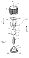
- a hair or beard trimmer as illustrated in Figure 1 and generally designated 1, comprises a housing 10 defining a gripping zone and being equipped at the bottom with a cutting head composed of a stationary cutting blade 11 and a movable cutting blade 12.
- the mower 1 also comprises at least one comb 2 intended to fit on the mower 1 detachably and movable by a slide 32 which will be explained later.
- Comb 2 includes a series fins that define a bearing plane 22 against the scalp of the user, the absolute distance between the support plane 22 and the cutting blades 11, 12 thus defines the length of the hair after cutting. This length is adjustable by the movement of the comb 2, the comb 2 being driven in translation by the slide 32.
- the mower has a setting means 5 in the form of a wheel as shown in FIG. Figure 1 , intended to undergo a rotational movement about its axis ⁇ in one direction or the other.
- the adjusting means 5 is movable in translation between two positions A and C, but can only be maintained at the position A and, according to a preferable variant of the invention, another position B, which corresponds to the retracted position of the adjusting means 5, the position B being between the position A and the position C.
- the adjusting means 5 is held in position A so that it is sufficiently out of the housing 10 to allow the user to take substantially all of its circumference 51 for easy and precise rotation manipulation. With the so-called retracted position B, we have the possibility of lowering the adjustment means 5 sufficiently low until rotation manipulation is impossible.
- this retraction means 4 comprises a latch 41 which is connected to the translation adjustment means 5 and which is at the same time rotatable about the axis ⁇ .
- the adjusting means 5 comprises two hooks 50 as illustrated in FIG. Figure 3 and the latch 41 comprises an orifice 411 in which the hooks 50 are inserted so that they make the adjustment means 5 dependent on the latch 41 in translation in the X direction.
- the upper surface 412 of the latch 41 is intended to press against a contact plane 52 of the adjusting means 5 so that the latter is actuated by the latch 41 in the direction Y which is opposite the direction X.
- the means adjustment is free in rotation relative to the lock.
- FIG. 2 It comprises a positioner 42 having a cylindrical shape positioned on the axis ⁇ , one end of the positioner 42 having a series of attachment arms 423 that can be embedded in cavities 442 distributed over a circumference of the drive wheel 44 which is also a circular part that can rotate around the axis ⁇ .
- the drive wheel 44 is rotated by the positioner 42 during adjustment.
- Other rotary attachment means could be considered as a bonding of the two parts or a slide connection, but the clipping solution proposed above has an economic and industrial advantage.
- the latch 41 Before mounting the positioner 42 on the drive wheel 44, it comes to place the latch 41 in the positioner 42 so that it can move on the axis ⁇ .
- the latch 41 has on its cylindrical surface a plurality of guide means 410 presented in the form of pins 410 intended to come into contact with the inner wall of the positioner 42. As illustrated in FIG.
- the positioner in order to be able to stop the latch in two different positions on the ⁇ axis, the positioner comprises on its inner wall shapes 422 comprising helical ramps 420 and reciprocally distributed grooves 421 and circular, so that when moving the latch 41 in the Y direction, all the pins 410 abut on either a helical ramp or a kerf.
- This movement of the latch 41 in the Y direction is actuated by a return means 43 which is positioned between the latch 41 and the drive wheel 44 and which is always in a compressed state. This makes it possible to keep the pins 410 against the shapes 422.
- the whole of the adjustment means 5 is substantially out of the box in order to give the user access to the adjustment, this position maintained is the position A which is an end of the path of the adjusting means 5.
- the adjusting means 5 is retracted to arrive at a position B which is flush with the housing 10 or slightly out of / back into the housing 10 to prohibit manipulation in rotation.
- the adjustment means 5 In order to pass the adjustment means 5 from one position to another, it suffices that the user exerts a pressing force on the adjustment means 5.
- the lock By compressing the return means 43, the lock moves in the direction X and the pins 410 leave shapes 422 until they touch the drive wheel 44.
- the adjustment means arrives at the position C which is the other end of its path.
- the first circumference of the drive wheel 44 which receives the pins 410 comprises a series of vertical teeth 440, these teeth are distributed so that each pin, down to the drive wheel, always slides on the same next to a tooth, which causes the latch 41 to slightly express angular movement in a single direction.
- the latch turns sufficiently that the pins move from one form to another without disturbing the function of the change of position of the adjusting means alternatively.
- the helical ramps 420 and the grooves 421 are spaced from the slopes 425, 426 that can help the rotation of the latch in the desired direction when it rises in the Y direction by the compressive force of the return means 43.
- the locking of the adjusting means 5 to the position A said output can be achieved by another intermediate piece that can operate directly on the adjustment means.
- the adjustment means 5 is rotatably connected to the positioner 42 by a sliding connection between the grooves 53 on the adjusting means 5 and the protruding lines 424 on the positioner 42.
- This connection allows the positioner 42 and the drive wheel 44 to rotate in one direction or the other around the axis ⁇ .
- This slide connection can be substituted by other means such as gluing or clipping,
- the drive wheel 44 comprises a first gear 441 forming part of a mechanical transmission means 3.
- This toothed wheel can be tapered or straight.
- the mechanical transmission means 3 also comprises a slider 31 which is a cylindrical piece mounted on the axis ⁇ 'and limited in translation relative to the housing, this slider 31 has at one end a second gear wheel 310 which forms with the first gear 441 a gear concurrent at an angle ⁇ . This angle as well as the size and number of teeth on each gear is adjusted to obtain optimum gearing and gear ratio.
- the mechanical transmission means 3 comprises a slide 32 fixed in rotation relative to the housing and intended to move on the axis ⁇ 'as illustrated in FIG. Figure 6 .
- the slider 32 includes portions of a tapping 320 in the form of protuberances spaced apart on its inner surface. These protuberances form with thread-like helices 311 on the outer surface of the slider 31 a screw-nut structure by means of which the slider 32 translates in translation on the axis ⁇ 'when the slider 31 is rotated around the slider. 'axis ⁇ '.
- the slide 32 receives the comb 2 by a clipping, the comb 2 can be driven by the slide 32 in translation in one direction or the other on the axis ⁇ '.
- This transmission principle also adapts to other embodiments, including a complete thread / tapping on the two parts or a thread on the slider 32 and a tapping on the slider 31, etc., the purpose being to transmit the rotation of the slider 31 in translation of the slider 32. It is also possible to adjust the size of the thread and / or the tapping defining the advance stroke ratio of the slider 32 in order to obtain a very precise adjustment.
- the number of teeth, the angle of the gearing and the threading / tapping can thus be varied very widely to obtain a ratio between the angular movement of the adjusting means and the translational movement of the comb.
- the mower 1 comprises, as illustrated in FIG. Figure 9 a feeler ring 6 having toothed bumps 61 which can push a feeling spring 7.
- the feeling ring 6 is fixed in rotation about the axis ⁇ on the drive wheel 44, it gives the user a sensation notch when rotating in one direction or the other.
- the angular dimension of the notched bumps 61 may be consistent with the rotational notches of the adjusting means 5 so that each notch sensation corresponds to the notch of the comb 2 advancement. But this may not be so if one simply wishes to indicate to the user that the setting is in progress.
- the support 8 is a reference piece comprising a cylinder 81 on the axis A, a cylinder 82 on the axis ⁇ ', and fastening means 83 for fixing the support 8 directly on the housing 10.
- This piece it can easily come to put the retraction means 4 in the cylinder 82 and the slider 31 on the cylinder 82 so that they are kept in position during operation.
- all the subsets of the retraction means 4 and the slider 31 keep very weak operating clearances between them, the range of dimensions is reduced and the dispersion is reduced. We thus obtain a device of better quality with satisfactory reliability of adjustment.
- the mower 1 has on the housing an indicator 9 which displays the cutting length instantly with the setting.
- the indicator 9 comprises an LCD screen on which the cutting length is displayed digitally.
- the indicator 9 picks up a signal which is a function of the position of a potentiometer 321 which is arranged on the slider 32. It is also possible to set up markings on the comb which are pointed by an arrow on the housing. of the mower.
- display means for example with LEDs (light emitting diodes) at different positions corresponding to a range of cutting lengths, but such a display makes the range very limiting.
- the mower 1 is suitable for a haircut or beard. It has therefore appeared to us that we need to supply several different size combs in order to widen the cutting length range. These combs are detachable from the slide and interchangeable between them.
Landscapes
- Life Sciences & Earth Sciences (AREA)
- Forests & Forestry (AREA)
- Engineering & Computer Science (AREA)
- Mechanical Engineering (AREA)
- Dry Shavers And Clippers (AREA)
- Harvester Elements (AREA)
Claims (13)
- Haarschneider (1) mit einem Gehäuse (10), das eine feststehende Klinge (11) und eine bewegliche Klinge (12) umfasst, die sich gegenüber der feststehenden Klinge (11) antreiben lässt, um einen Schnitt auszuführen, wobei das Gehäuse (10) mit zumindest einem Kamm (2) ausgestattet ist, der zwischen den Schneidklingen und der Kopfhaut angeordnet wird und sich gegenüber dem Gehäuse (10) verschieben lässt, wobei sich die Verschiebung des Kamms (2) von Einstellmitteln (5) steuern lässt, die mit dem genannten Kamm (2) über mechanische Übertragungsmittel (3) verbunden sind, wobei die genannten Einstellmittel (5) durch Rückzugmittel (4) in zumindest einer ersten, gegenüber dem Gehäuse (10) vorgeschobenen Position (A) gehalten werden, dadurch gekennzeichnet, dass die Einstellmittel (5) bei der Einstellung eine Drehbewegung um ihre Achse Δ erfahren, wobei die Einstellmittel in der genannten ersten vorgeschobenen Position (A) gehalten werden, und dass die Einstellmittel (5) in einer zweiten, gegenüber der genannten ersten vorgeschobenen Position (A) zurückgezogenen Position (B) gehalten werden.
- Haarschneider nach dem vorhergehenden Anspruch, dadurch gekennzeichnet, dass die genannten Rückzugmittel (4) ein Verriegelungselement (41) umfassen, das sich in einem Positionierelement (42) verschiebt, welches mit den genannten Einstellmitteln (5) zusammenwirkt, wenn das genannte Verriegelungselement (41) von Rückstellmitteln (43) oder einer Auflagekraft beansprucht wird, wobei das genannte Positionierelement (42) drehfest mit einem Antriebsrad (44) verbunden ist, das mit den genannten mechanischen Übertragungsmitteln (3) zusammenwirkt.
- Haarschneider nach dem vorhergehenden Anspruch, dadurch gekennzeichnet, dass das genannte Verriegelungselement (41) zumindest ein Führungselement (410) umfasst, das in Formen (422) auf der Innenwand des genannten Positionierelements (42) gleitet, wobei die genannten Formen (422) spiralförmige Rampen (420) und Schlitze (421) umfassen, die abwechselnd das genannte Führungselement (410) in zwei verschiedenen Positionen arretieren, wenn das genannte Verriegelungselement (41) drehend von einer Reihe vertikaler Zähne (440) auf einem ersten Umfang des genannten Antriebsrades (44) geführt wird, wobei die genannte Reihe vertikaler Zähne (440) das genannte Führungselement (410) derart aufnimmt, dass das genannte Verriegelungselement (41) immer so angetrieben wird, dass es sich in der gleichen Richtung dreht.
- Haarschneider nach einem der Ansprüche 2 oder 3, dadurch gekennzeichnet, dass das genannte Antriebsrad (44) auf einem zweiten Umfang ein erstes Zahnrad (441) umfasst.
- Haarschneider nach dem vorhergehenden Anspruch, dadurch gekennzeichnet, dass die genannten mechanischen Übertragungsmittel (3) einen Stellring (31) mit einem zweiten Zahnrad (310) umfassen, das mit dem genannten ersten Zahnrad (441) des genannten Antriebsrads (44) ein Zahnradpaar bildet, das sich unter einem Winkel α abwälzt.
- Haarschneider nach dem vorhergehenden Anspruch, dadurch gekennzeichnet, dass der genannte Stellring (31) zumindest einen Wendel (311) vom Typ eines Gewindes umfasst, der mit einem Gleitstück (32) zusammenwirkt, das zumindest einen Teil eines Innengewindes (320) umfasst, das dem genannten Wendel (311) entspricht, wobei das genannte Gleitstück (32) den genannten Kamm (2) durch Aufklemmen aufnimmt.
- Haarschneider nach einem der Ansprüche 2 bis 6, dadurch gekennzeichnet, dass die genannten Einstellmittel (5) durch die Kupplung zwischen zumindest einem Haken (50) an einem von entweder den Einstellmitteln (5) oder dem Verriegelungselement (41) und einer Öffnung (411) an dem anderen von entweder den Einstellmitteln (5) oder dem Verriegelungselement (41) verschiebbar mit den Rückzugmitteln (4) verbunden sind.
- Haarschneider nach einem der Ansprüche 2 bis 7, dadurch gekennzeichnet, dass die genannten Einstellmittel (5) mit den Rückzugmitteln (4) durch eine Gleitverbindung zwischen den genannten Einstellmitteln (5) und dem genannten Positionierelement (42) drehfest verbunden sind.
- Haarschneider nach einem der Ansprüche 2 bis 8, dadurch gekennzeichnet, dass das genannte Antriebsrad (44) koaxial einen Kraftschlussring (6) mit Erhebungen (61) am Umfang umfasst, die auf eine Kraftschlussfeder (7) wirken.
- Haarschneider nach einem der Ansprüche 5 bis 8, dadurch gekennzeichnet, dass Einstellmittel (5), Verriegelungselement (41), Positionierelement (42), Antriebsrad (44) und Stellring (31) auf einem einzigen Trägerteil (8) montiert und auf diesem an Ort und Stelle gehalten werden.
- Haarschneider nach einem der vorhergehenden Ansprüche, dadurch gekennzeichnet, dass das genannte Gehäuse (10) eine Anzeige (9) der Schnittlänge umfasst.
- Haarschneider nach den Ansprüchen 6 und 11, dadurch gekennzeichnet, dass das genannte Gleitstück (32) ein Potentiometer (321) umfasst, das der genannten Anzeige (9) die Position des Kamms in einem Bereich möglicher Einstellungen angeben kann.
- Haarschneider nach einem der vorhergehenden Ansprüche, dadurch gekennzeichnet, dass er zumindest zwei abnehmbare Kämme unterschiedlicher Größe umfasst.
Applications Claiming Priority (1)
| Application Number | Priority Date | Filing Date | Title |
|---|---|---|---|
| FR1162502A FR2985211B1 (fr) | 2011-12-28 | 2011-12-28 | Tondeuse avec molette retractable |
Publications (2)
| Publication Number | Publication Date |
|---|---|
| EP2610039A1 EP2610039A1 (de) | 2013-07-03 |
| EP2610039B1 true EP2610039B1 (de) | 2015-10-14 |
Family
ID=47358042
Family Applications (1)
| Application Number | Title | Priority Date | Filing Date |
|---|---|---|---|
| EP12198716.8A Active EP2610039B1 (de) | 2011-12-28 | 2012-12-20 | Haarschneidemaschine mit einrückbarem Rad |
Country Status (4)
| Country | Link |
|---|---|
| EP (1) | EP2610039B1 (de) |
| CN (1) | CN203185376U (de) |
| ES (1) | ES2559377T3 (de) |
| FR (1) | FR2985211B1 (de) |
Families Citing this family (10)
| Publication number | Priority date | Publication date | Assignee | Title |
|---|---|---|---|---|
| EP2332701A1 (de) * | 2009-12-14 | 2011-06-15 | Koninklijke Philips Electronics N.V. | Vorrichtung mit Drehelement |
| JP5923750B2 (ja) * | 2012-04-06 | 2016-05-25 | パナソニックIpマネジメント株式会社 | バリカン |
| CN103950046A (zh) * | 2014-04-10 | 2014-07-30 | 浙江百特电器有限公司 | 一种用于调节限位梳剃毛长度的装置 |
| WO2015169633A1 (en) * | 2014-05-09 | 2015-11-12 | Koninklijke Philips N.V. | Adjustable spacing comb, adjustment drive and hair cutting appliance |
| BR112016025847B1 (pt) | 2014-05-09 | 2021-06-22 | Koninklijke Philips N.V. | Acionador de ajuste para um pente com espaçamento ajustável de um aparelho para corte de pelos, pente com espaçamento ajustável de um aparelho para corte de pelos, aparelho para corte de pelos, e, método para operar um pente com espaçamento ajustável de um aparelho para corte de pelos |
| RU2705281C2 (ru) * | 2014-09-18 | 2019-11-06 | Конинклейке Филипс Н.В. | Гребень с регулируемым зазором, привод регулировки и прибор для стрижки волос |
| RU2738878C2 (ru) * | 2016-10-14 | 2020-12-17 | Конинклейке Филипс Н.В. | Механизм регулирования длины подстригания, регулировочный привод и прибор для стрижки волос |
| CN109849060A (zh) * | 2018-12-29 | 2019-06-07 | 浙江月立电器有限公司 | 电推剪及其控制方法 |
| CN115056268B (zh) * | 2022-05-06 | 2024-08-20 | 利民(番禺南沙)电器发展有限公司 | 一种理发器 |
| EP4600002A1 (de) * | 2024-02-06 | 2025-08-13 | Koninklijke Philips N.V. | Kamm mit einstellbarem abstand und haarschneidegerät |
Family Cites Families (7)
| Publication number | Priority date | Publication date | Assignee | Title |
|---|---|---|---|---|
| US4085503A (en) * | 1974-12-23 | 1978-04-25 | Sunbeam Corporation | Electric dry shaver with adjustable long hair trimmer |
| WO1998025734A1 (en) * | 1996-12-13 | 1998-06-18 | Koninklijke Philips Electronics N.V. | Hair-cutting system including a hair-cutting apparatus and including a comb device which can be mounted onto the apparatus and which has two spring-loaded comb sections |
| US6807736B2 (en) | 2001-09-25 | 2004-10-26 | Wahl Clipper Corporation | Color-coded attachment comb key for hair clipper |
| JP4103873B2 (ja) * | 2004-09-01 | 2008-06-18 | 松下電工株式会社 | ヘアカッターのコーム振動防止構造 |
| PL1710055T3 (pl) | 2005-07-07 | 2008-02-29 | Faco Sa | Maszynka do strzyżenia włosów ze zmechanizowaną prowadnicą cięcia |
| DE102007008622A1 (de) * | 2007-02-22 | 2008-08-28 | Braun Gmbh | Haarschneidegerät |
| EP2332701A1 (de) | 2009-12-14 | 2011-06-15 | Koninklijke Philips Electronics N.V. | Vorrichtung mit Drehelement |
-
2011
- 2011-12-28 FR FR1162502A patent/FR2985211B1/fr not_active Expired - Fee Related
-
2012
- 2012-12-20 ES ES12198716.8T patent/ES2559377T3/es active Active
- 2012-12-20 EP EP12198716.8A patent/EP2610039B1/de active Active
- 2012-12-26 CN CN 201220728360 patent/CN203185376U/zh not_active Expired - Lifetime
Also Published As
| Publication number | Publication date |
|---|---|
| FR2985211B1 (fr) | 2014-08-29 |
| EP2610039A1 (de) | 2013-07-03 |
| CN203185376U (zh) | 2013-09-11 |
| FR2985211A1 (fr) | 2013-07-05 |
| ES2559377T3 (es) | 2016-02-11 |
Similar Documents
| Publication | Publication Date | Title |
|---|---|---|
| EP2610039A1 (de) | Haarschneidemaschine mit einrückbarem Rad | |
| EP0809457B1 (de) | Elektrisch betriebener handschläger und -rührer | |
| EP1677633B1 (de) | Zigarrenschneider | |
| EP2735298B1 (de) | Massagegerät mit einem Massagekopf, der mit Tüllen ausgestattet ist, die sich zur Mitte des Kopfes verschieben | |
| EP2766153B1 (de) | Präzisionsrasierapparat | |
| FR2946492A3 (fr) | Coupe-herbe | |
| EP2821048B1 (de) | Pflegegerät mit leichter Montage des Gerätekopfs | |
| FR2837407A1 (fr) | Systeme de positionnement du rotor et d'indexation d'un broyeur a percussion | |
| FR2903929A1 (fr) | Tondeuse a cheveux a reglage assiste de la hauteur de coupe | |
| EP2676777B1 (de) | Elektrischer Rasierapparat mit neuer Befestigung eines Schneidkopfes | |
| FR2656574A1 (fr) | Phare pour vehicule a faisceau orientable. | |
| EP3890576B1 (de) | Deckel für küchengerät mit manuell betriebener seilvorrichtung | |
| EP3034252B1 (de) | Gerät zum schneiden von lebensmitteln in scheiben, stifte, würfel oder sehr feine streifen | |
| WO2014096715A1 (fr) | Appareil de decoupe d'aliments a mouvement alternatif avec commande de securite | |
| EP2353366B1 (de) | Astschere zum Schneiden von Pflanzen | |
| EP0869858B1 (de) | Bearbeitungseinheit mit rotierendem kopf | |
| FR3072435A1 (fr) | Boitier de transmission et engin roulant equipe d'un tel boitier | |
| EP2781319B1 (de) | Körperrasierapparat | |
| FR2740943A1 (fr) | Machine a grigner | |
| EP0891149B1 (de) | Abgabewelle für handtuchmaterial in einem spender mit regulierungsvorrichtung für die länge des abzugebenden materials | |
| FR2690880A1 (fr) | Dispositif d'articulation de siège, en particulier de véhicule automobile. | |
| EP0038261B1 (de) | Vorrichtungen zum Füllen von Behältern | |
| EP0014617A1 (de) | Apparat zum Aufschneiden und Schnitzeln von Nahrungsmitteln | |
| EP2505110A1 (de) | Reibevorrichtung für Lebensmittel, insbesondere für Käse | |
| FR2660547A1 (fr) | Appareil chirurgical pour realiser une decoupe conique de la cornee. |
Legal Events
| Date | Code | Title | Description |
|---|---|---|---|
| PUAI | Public reference made under article 153(3) epc to a published international application that has entered the european phase |
Free format text: ORIGINAL CODE: 0009012 |
|
| AK | Designated contracting states |
Kind code of ref document: A1 Designated state(s): AL AT BE BG CH CY CZ DE DK EE ES FI FR GB GR HR HU IE IS IT LI LT LU LV MC MK MT NL NO PL PT RO RS SE SI SK SM TR |
|
| AX | Request for extension of the european patent |
Extension state: BA ME |
|
| 17P | Request for examination filed |
Effective date: 20131219 |
|
| RBV | Designated contracting states (corrected) |
Designated state(s): AL AT BE BG CH CY CZ DE DK EE ES FI FR GB GR HR HU IE IS IT LI LT LU LV MC MK MT NL NO PL PT RO RS SE SI SK SM TR |
|
| 17Q | First examination report despatched |
Effective date: 20140708 |
|
| GRAP | Despatch of communication of intention to grant a patent |
Free format text: ORIGINAL CODE: EPIDOSNIGR1 |
|
| INTG | Intention to grant announced |
Effective date: 20150506 |
|
| GRAS | Grant fee paid |
Free format text: ORIGINAL CODE: EPIDOSNIGR3 |
|
| GRAA | (expected) grant |
Free format text: ORIGINAL CODE: 0009210 |
|
| AK | Designated contracting states |
Kind code of ref document: B1 Designated state(s): AL AT BE BG CH CY CZ DE DK EE ES FI FR GB GR HR HU IE IS IT LI LT LU LV MC MK MT NL NO PL PT RO RS SE SI SK SM TR |
|
| REG | Reference to a national code |
Ref country code: GB Ref legal event code: FG4D Free format text: NOT ENGLISH |
|
| REG | Reference to a national code |
Ref country code: AT Ref legal event code: REF Ref document number: 754759 Country of ref document: AT Kind code of ref document: T Effective date: 20151015 Ref country code: CH Ref legal event code: EP |
|
| REG | Reference to a national code |
Ref country code: IE Ref legal event code: FG4D Free format text: LANGUAGE OF EP DOCUMENT: FRENCH |
|
| REG | Reference to a national code |
Ref country code: DE Ref legal event code: R096 Ref document number: 602012011507 Country of ref document: DE |
|
| REG | Reference to a national code |
Ref country code: FR Ref legal event code: PLFP Year of fee payment: 4 |
|
| REG | Reference to a national code |
Ref country code: ES Ref legal event code: FG2A Ref document number: 2559377 Country of ref document: ES Kind code of ref document: T3 Effective date: 20160211 |
|
| REG | Reference to a national code |
Ref country code: NL Ref legal event code: MP Effective date: 20151014 |
|
| REG | Reference to a national code |
Ref country code: LT Ref legal event code: MG4D |
|
| REG | Reference to a national code |
Ref country code: AT Ref legal event code: MK05 Ref document number: 754759 Country of ref document: AT Kind code of ref document: T Effective date: 20151014 |
|
| PG25 | Lapsed in a contracting state [announced via postgrant information from national office to epo] |
Ref country code: IS Free format text: LAPSE BECAUSE OF FAILURE TO SUBMIT A TRANSLATION OF THE DESCRIPTION OR TO PAY THE FEE WITHIN THE PRESCRIBED TIME-LIMIT Effective date: 20160214 Ref country code: NO Free format text: LAPSE BECAUSE OF FAILURE TO SUBMIT A TRANSLATION OF THE DESCRIPTION OR TO PAY THE FEE WITHIN THE PRESCRIBED TIME-LIMIT Effective date: 20160114 Ref country code: HR Free format text: LAPSE BECAUSE OF FAILURE TO SUBMIT A TRANSLATION OF THE DESCRIPTION OR TO PAY THE FEE WITHIN THE PRESCRIBED TIME-LIMIT Effective date: 20151014 Ref country code: LT Free format text: LAPSE BECAUSE OF FAILURE TO SUBMIT A TRANSLATION OF THE DESCRIPTION OR TO PAY THE FEE WITHIN THE PRESCRIBED TIME-LIMIT Effective date: 20151014 Ref country code: NL Free format text: LAPSE BECAUSE OF FAILURE TO SUBMIT A TRANSLATION OF THE DESCRIPTION OR TO PAY THE FEE WITHIN THE PRESCRIBED TIME-LIMIT Effective date: 20151014 |
|
| PG25 | Lapsed in a contracting state [announced via postgrant information from national office to epo] |
Ref country code: PT Free format text: LAPSE BECAUSE OF FAILURE TO SUBMIT A TRANSLATION OF THE DESCRIPTION OR TO PAY THE FEE WITHIN THE PRESCRIBED TIME-LIMIT Effective date: 20160215 Ref country code: SE Free format text: LAPSE BECAUSE OF FAILURE TO SUBMIT A TRANSLATION OF THE DESCRIPTION OR TO PAY THE FEE WITHIN THE PRESCRIBED TIME-LIMIT Effective date: 20151014 Ref country code: GR Free format text: LAPSE BECAUSE OF FAILURE TO SUBMIT A TRANSLATION OF THE DESCRIPTION OR TO PAY THE FEE WITHIN THE PRESCRIBED TIME-LIMIT Effective date: 20160115 Ref country code: LV Free format text: LAPSE BECAUSE OF FAILURE TO SUBMIT A TRANSLATION OF THE DESCRIPTION OR TO PAY THE FEE WITHIN THE PRESCRIBED TIME-LIMIT Effective date: 20151014 Ref country code: FI Free format text: LAPSE BECAUSE OF FAILURE TO SUBMIT A TRANSLATION OF THE DESCRIPTION OR TO PAY THE FEE WITHIN THE PRESCRIBED TIME-LIMIT Effective date: 20151014 Ref country code: PL Free format text: LAPSE BECAUSE OF FAILURE TO SUBMIT A TRANSLATION OF THE DESCRIPTION OR TO PAY THE FEE WITHIN THE PRESCRIBED TIME-LIMIT Effective date: 20151014 Ref country code: BE Free format text: LAPSE BECAUSE OF NON-PAYMENT OF DUE FEES Effective date: 20151231 Ref country code: AT Free format text: LAPSE BECAUSE OF FAILURE TO SUBMIT A TRANSLATION OF THE DESCRIPTION OR TO PAY THE FEE WITHIN THE PRESCRIBED TIME-LIMIT Effective date: 20151014 Ref country code: RS Free format text: LAPSE BECAUSE OF FAILURE TO SUBMIT A TRANSLATION OF THE DESCRIPTION OR TO PAY THE FEE WITHIN THE PRESCRIBED TIME-LIMIT Effective date: 20151014 |
|
| REG | Reference to a national code |
Ref country code: DE Ref legal event code: R119 Ref document number: 602012011507 Country of ref document: DE |
|
| PG25 | Lapsed in a contracting state [announced via postgrant information from national office to epo] |
Ref country code: CZ Free format text: LAPSE BECAUSE OF FAILURE TO SUBMIT A TRANSLATION OF THE DESCRIPTION OR TO PAY THE FEE WITHIN THE PRESCRIBED TIME-LIMIT Effective date: 20151014 Ref country code: LU Free format text: LAPSE BECAUSE OF FAILURE TO SUBMIT A TRANSLATION OF THE DESCRIPTION OR TO PAY THE FEE WITHIN THE PRESCRIBED TIME-LIMIT Effective date: 20151220 Ref country code: MC Free format text: LAPSE BECAUSE OF FAILURE TO SUBMIT A TRANSLATION OF THE DESCRIPTION OR TO PAY THE FEE WITHIN THE PRESCRIBED TIME-LIMIT Effective date: 20151014 |
|
| REG | Reference to a national code |
Ref country code: CH Ref legal event code: PL |
|
| PLBE | No opposition filed within time limit |
Free format text: ORIGINAL CODE: 0009261 |
|
| STAA | Information on the status of an ep patent application or granted ep patent |
Free format text: STATUS: NO OPPOSITION FILED WITHIN TIME LIMIT |
|
| PG25 | Lapsed in a contracting state [announced via postgrant information from national office to epo] |
Ref country code: EE Free format text: LAPSE BECAUSE OF FAILURE TO SUBMIT A TRANSLATION OF THE DESCRIPTION OR TO PAY THE FEE WITHIN THE PRESCRIBED TIME-LIMIT Effective date: 20151014 Ref country code: SK Free format text: LAPSE BECAUSE OF FAILURE TO SUBMIT A TRANSLATION OF THE DESCRIPTION OR TO PAY THE FEE WITHIN THE PRESCRIBED TIME-LIMIT Effective date: 20151014 Ref country code: RO Free format text: LAPSE BECAUSE OF FAILURE TO SUBMIT A TRANSLATION OF THE DESCRIPTION OR TO PAY THE FEE WITHIN THE PRESCRIBED TIME-LIMIT Effective date: 20151014 Ref country code: SM Free format text: LAPSE BECAUSE OF FAILURE TO SUBMIT A TRANSLATION OF THE DESCRIPTION OR TO PAY THE FEE WITHIN THE PRESCRIBED TIME-LIMIT Effective date: 20151014 Ref country code: DK Free format text: LAPSE BECAUSE OF FAILURE TO SUBMIT A TRANSLATION OF THE DESCRIPTION OR TO PAY THE FEE WITHIN THE PRESCRIBED TIME-LIMIT Effective date: 20151014 |
|
| 26N | No opposition filed |
Effective date: 20160715 |
|
| REG | Reference to a national code |
Ref country code: IE Ref legal event code: MM4A |
|
| PG25 | Lapsed in a contracting state [announced via postgrant information from national office to epo] |
Ref country code: DE Free format text: LAPSE BECAUSE OF NON-PAYMENT OF DUE FEES Effective date: 20160701 Ref country code: IE Free format text: LAPSE BECAUSE OF NON-PAYMENT OF DUE FEES Effective date: 20151220 Ref country code: LI Free format text: LAPSE BECAUSE OF NON-PAYMENT OF DUE FEES Effective date: 20151231 Ref country code: CH Free format text: LAPSE BECAUSE OF NON-PAYMENT OF DUE FEES Effective date: 20151231 |
|
| PG25 | Lapsed in a contracting state [announced via postgrant information from national office to epo] |
Ref country code: SI Free format text: LAPSE BECAUSE OF FAILURE TO SUBMIT A TRANSLATION OF THE DESCRIPTION OR TO PAY THE FEE WITHIN THE PRESCRIBED TIME-LIMIT Effective date: 20151014 |
|
| REG | Reference to a national code |
Ref country code: FR Ref legal event code: PLFP Year of fee payment: 5 |
|
| PG25 | Lapsed in a contracting state [announced via postgrant information from national office to epo] |
Ref country code: BG Free format text: LAPSE BECAUSE OF FAILURE TO SUBMIT A TRANSLATION OF THE DESCRIPTION OR TO PAY THE FEE WITHIN THE PRESCRIBED TIME-LIMIT Effective date: 20151014 Ref country code: HU Free format text: LAPSE BECAUSE OF FAILURE TO SUBMIT A TRANSLATION OF THE DESCRIPTION OR TO PAY THE FEE WITHIN THE PRESCRIBED TIME-LIMIT; INVALID AB INITIO Effective date: 20121220 |
|
| REG | Reference to a national code |
Ref country code: FR Ref legal event code: CA Effective date: 20170518 |
|
| PG25 | Lapsed in a contracting state [announced via postgrant information from national office to epo] |
Ref country code: CY Free format text: LAPSE BECAUSE OF FAILURE TO SUBMIT A TRANSLATION OF THE DESCRIPTION OR TO PAY THE FEE WITHIN THE PRESCRIBED TIME-LIMIT Effective date: 20151014 |
|
| GBPC | Gb: european patent ceased through non-payment of renewal fee |
Effective date: 20161220 |
|
| PG25 | Lapsed in a contracting state [announced via postgrant information from national office to epo] |
Ref country code: MT Free format text: LAPSE BECAUSE OF FAILURE TO SUBMIT A TRANSLATION OF THE DESCRIPTION OR TO PAY THE FEE WITHIN THE PRESCRIBED TIME-LIMIT Effective date: 20151014 |
|
| PG25 | Lapsed in a contracting state [announced via postgrant information from national office to epo] |
Ref country code: GB Free format text: LAPSE BECAUSE OF NON-PAYMENT OF DUE FEES Effective date: 20161220 |
|
| REG | Reference to a national code |
Ref country code: FR Ref legal event code: PLFP Year of fee payment: 6 |
|
| PG25 | Lapsed in a contracting state [announced via postgrant information from national office to epo] |
Ref country code: TR Free format text: LAPSE BECAUSE OF FAILURE TO SUBMIT A TRANSLATION OF THE DESCRIPTION OR TO PAY THE FEE WITHIN THE PRESCRIBED TIME-LIMIT Effective date: 20151014 Ref country code: MK Free format text: LAPSE BECAUSE OF FAILURE TO SUBMIT A TRANSLATION OF THE DESCRIPTION OR TO PAY THE FEE WITHIN THE PRESCRIBED TIME-LIMIT Effective date: 20151014 |
|
| PG25 | Lapsed in a contracting state [announced via postgrant information from national office to epo] |
Ref country code: AL Free format text: LAPSE BECAUSE OF FAILURE TO SUBMIT A TRANSLATION OF THE DESCRIPTION OR TO PAY THE FEE WITHIN THE PRESCRIBED TIME-LIMIT Effective date: 20151014 |
|
| PGFP | Annual fee paid to national office [announced via postgrant information from national office to epo] |
Ref country code: IT Payment date: 20201211 Year of fee payment: 9 |
|
| PGFP | Annual fee paid to national office [announced via postgrant information from national office to epo] |
Ref country code: ES Payment date: 20210107 Year of fee payment: 9 |
|
| PG25 | Lapsed in a contracting state [announced via postgrant information from national office to epo] |
Ref country code: IT Free format text: LAPSE BECAUSE OF NON-PAYMENT OF DUE FEES Effective date: 20211220 |
|
| REG | Reference to a national code |
Ref country code: ES Ref legal event code: FD2A Effective date: 20230329 |
|
| PG25 | Lapsed in a contracting state [announced via postgrant information from national office to epo] |
Ref country code: ES Free format text: LAPSE BECAUSE OF NON-PAYMENT OF DUE FEES Effective date: 20211221 |
|
| P01 | Opt-out of the competence of the unified patent court (upc) registered |
Effective date: 20230517 |
|
| PGFP | Annual fee paid to national office [announced via postgrant information from national office to epo] |
Ref country code: FR Payment date: 20251230 Year of fee payment: 14 |