EP2610020B1 - Methods of skiving metal and forming a fin in a heat exchanger - Google Patents
Methods of skiving metal and forming a fin in a heat exchanger Download PDFInfo
- Publication number
- EP2610020B1 EP2610020B1 EP12196903.4A EP12196903A EP2610020B1 EP 2610020 B1 EP2610020 B1 EP 2610020B1 EP 12196903 A EP12196903 A EP 12196903A EP 2610020 B1 EP2610020 B1 EP 2610020B1
- Authority
- EP
- European Patent Office
- Prior art keywords
- forming
- nick
- nicks
- metal material
- metal
- Prior art date
- Legal status (The legal status is an assumption and is not a legal conclusion. Google has not performed a legal analysis and makes no representation as to the accuracy of the status listed.)
- Active
Links
- 229910052751 metal Inorganic materials 0.000 title claims description 39
- 239000002184 metal Substances 0.000 title claims description 39
- 238000000034 method Methods 0.000 title claims description 22
- 239000007769 metal material Substances 0.000 claims description 18
- 239000000463 material Substances 0.000 claims description 17
- PXHVJJICTQNCMI-UHFFFAOYSA-N Nickel Chemical compound [Ni] PXHVJJICTQNCMI-UHFFFAOYSA-N 0.000 claims description 11
- 229910052782 aluminium Inorganic materials 0.000 claims description 10
- XAGFODPZIPBFFR-UHFFFAOYSA-N aluminium Chemical compound [Al] XAGFODPZIPBFFR-UHFFFAOYSA-N 0.000 claims description 10
- 239000012530 fluid Substances 0.000 claims description 9
- 229910052759 nickel Inorganic materials 0.000 claims description 5
- 230000001154 acute effect Effects 0.000 claims description 4
- 229910000990 Ni alloy Inorganic materials 0.000 claims description 3
- RYGMFSIKBFXOCR-UHFFFAOYSA-N Copper Chemical compound [Cu] RYGMFSIKBFXOCR-UHFFFAOYSA-N 0.000 description 4
- 229910052802 copper Inorganic materials 0.000 description 4
- 239000010949 copper Substances 0.000 description 4
- 229910045601 alloy Inorganic materials 0.000 description 1
- 239000000956 alloy Substances 0.000 description 1
- 238000005452 bending Methods 0.000 description 1
- 230000015572 biosynthetic process Effects 0.000 description 1
- 238000005530 etching Methods 0.000 description 1
- 206010016256 fatigue Diseases 0.000 description 1
- 238000007373 indentation Methods 0.000 description 1
- 230000001788 irregular Effects 0.000 description 1
- 238000004519 manufacturing process Methods 0.000 description 1
- 238000002844 melting Methods 0.000 description 1
- 230000008018 melting Effects 0.000 description 1
- 238000003801 milling Methods 0.000 description 1
Images


Classifications
-
- B—PERFORMING OPERATIONS; TRANSPORTING
- B21—MECHANICAL METAL-WORKING WITHOUT ESSENTIALLY REMOVING MATERIAL; PUNCHING METAL
- B21J—FORGING; HAMMERING; PRESSING METAL; RIVETING; FORGE FURNACES
- B21J5/00—Methods for forging, hammering, or pressing; Special equipment or accessories therefor
- B21J5/06—Methods for forging, hammering, or pressing; Special equipment or accessories therefor for performing particular operations
- B21J5/068—Shaving, skiving or scarifying for forming lifted portions, e.g. slices or barbs, on the surface of the material
-
- B—PERFORMING OPERATIONS; TRANSPORTING
- B23—MACHINE TOOLS; METAL-WORKING NOT OTHERWISE PROVIDED FOR
- B23H—WORKING OF METAL BY THE ACTION OF A HIGH CONCENTRATION OF ELECTRIC CURRENT ON A WORKPIECE USING AN ELECTRODE WHICH TAKES THE PLACE OF A TOOL; SUCH WORKING COMBINED WITH OTHER FORMS OF WORKING OF METAL
- B23H9/00—Machining specially adapted for treating particular metal objects or for obtaining special effects or results on metal objects
-
- F—MECHANICAL ENGINEERING; LIGHTING; HEATING; WEAPONS; BLASTING
- F28—HEAT EXCHANGE IN GENERAL
- F28F—DETAILS OF HEAT-EXCHANGE AND HEAT-TRANSFER APPARATUS, OF GENERAL APPLICATION
- F28F3/00—Plate-like or laminated elements; Assemblies of plate-like or laminated elements
- F28F3/02—Elements or assemblies thereof with means for increasing heat-transfer area, e.g. with fins, with recesses, with corrugations
- F28F3/04—Elements or assemblies thereof with means for increasing heat-transfer area, e.g. with fins, with recesses, with corrugations the means being integral with the element
- F28F3/048—Elements or assemblies thereof with means for increasing heat-transfer area, e.g. with fins, with recesses, with corrugations the means being integral with the element in the form of ribs integral with the element or local variations in thickness of the element, e.g. grooves, microchannels
-
- B—PERFORMING OPERATIONS; TRANSPORTING
- B23—MACHINE TOOLS; METAL-WORKING NOT OTHERWISE PROVIDED FOR
- B23H—WORKING OF METAL BY THE ACTION OF A HIGH CONCENTRATION OF ELECTRIC CURRENT ON A WORKPIECE USING AN ELECTRODE WHICH TAKES THE PLACE OF A TOOL; SUCH WORKING COMBINED WITH OTHER FORMS OF WORKING OF METAL
- B23H7/00—Processes or apparatus applicable to both electrical discharge machining and electrochemical machining
- B23H7/02—Wire-cutting
-
- B—PERFORMING OPERATIONS; TRANSPORTING
- B23—MACHINE TOOLS; METAL-WORKING NOT OTHERWISE PROVIDED FOR
- B23P—METAL-WORKING NOT OTHERWISE PROVIDED FOR; COMBINED OPERATIONS; UNIVERSAL MACHINE TOOLS
- B23P2700/00—Indexing scheme relating to the articles being treated, e.g. manufactured, repaired, assembled, connected or other operations covered in the subgroups
- B23P2700/10—Heat sinks
-
- Y—GENERAL TAGGING OF NEW TECHNOLOGICAL DEVELOPMENTS; GENERAL TAGGING OF CROSS-SECTIONAL TECHNOLOGIES SPANNING OVER SEVERAL SECTIONS OF THE IPC; TECHNICAL SUBJECTS COVERED BY FORMER USPC CROSS-REFERENCE ART COLLECTIONS [XRACs] AND DIGESTS
- Y10—TECHNICAL SUBJECTS COVERED BY FORMER USPC
- Y10T—TECHNICAL SUBJECTS COVERED BY FORMER US CLASSIFICATION
- Y10T83/00—Cutting
- Y10T83/02—Other than completely through work thickness
- Y10T83/0207—Other than completely through work thickness or through work presented
-
- Y—GENERAL TAGGING OF NEW TECHNOLOGICAL DEVELOPMENTS; GENERAL TAGGING OF CROSS-SECTIONAL TECHNOLOGIES SPANNING OVER SEVERAL SECTIONS OF THE IPC; TECHNICAL SUBJECTS COVERED BY FORMER USPC CROSS-REFERENCE ART COLLECTIONS [XRACs] AND DIGESTS
- Y10—TECHNICAL SUBJECTS COVERED BY FORMER USPC
- Y10T—TECHNICAL SUBJECTS COVERED BY FORMER US CLASSIFICATION
- Y10T83/00—Cutting
- Y10T83/04—Processes
Definitions
- Skiving may be generally used to produce a series of very fine integrated shavings on a metal body and the shavings may all have generally the same shape and size.
- a heat exchanger manufacturer may use the skiving technique to create metal fins where the fin of the heat exchanger then provides a way to transfer heat from one medium to another. Integral fins formed from the parent material have a significantly higher heat transfer coefficient versus fins which may be brazed or otherwise attached to the metal body.
- the fins of such heat exchangers provide large surface areas required for transferring heat to the surrounding air.
- Usually such fins are skived out of a single block of metal such as copper or aluminum, which are materials currently used on low temperature applications.
- JP 54-68554 relates to the manufacture of a heat conducting wall and discloses features generally corresponding to the preamble of claim 1 herein.
- a method of skiving metal using a skiving blade is provided in accordance with claim 1 herein.
- a method of forming fins in a heat exchanger is provided in accordance with claim 13 herein.
- a nearly pure nickel material such as nickel 201, or some alloys of nickel may be desired as it has a high heat transfer coefficient and is suitable for such an environment.
- nickel and its relevant high-temperature alloys are relatively hard materials, much harder than aluminum and copper, it is also difficult to skive and currently known skiving techniques do not result in uniform shavings that are repeatable.
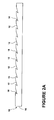
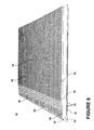
- FIG 1 illustrates that in nickel or a similarly hard metal material 2 that is worked according to current skiving practices, the shavings 4 that are formed are very irregular both in size and in spacing. Further, a cutting tool (not shown) used for forming the shavings 4 will not have a long life because the cutting tool will skate along the surface 6 of the hard metal material 2 until enough pressure is built up at the nose of the cutting tool to enter into the hard metal material 2. This excess pressure causes the cutting tool nose to wear more quickly, and puts a larger bending load on the cutting tool nose, which in turn can lead to early fatigue of the cutting tool.
- a method of skiving metal having a hardness greater than aluminum, including a metal body 10, may include forming a nick 12 in a surface 14 of the metal body 10 as shown in Figure 2A . It is contemplated that the nick 12 in the surface 14 may be formed in any suitable manner.
- forming the nick 12 may include etching the surface 14, cutting the surface 14 with an EDM wire (not shown), or cutting the surface 14 with a dovetail type milling cutter (not shown).
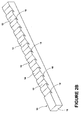
- Figure 2B shows the metal body 10 in perspective; it may be understood that the nick 12 may be made along a width of the metal body 10.
- Forming the nick 12 may include forming a plurality of nicks 12. Such a plurality of nicks 12 may be in a row.
- Forming the plurality of nicks 12 in a row may include forming multiple rows of nicks 12 on the width of metal body 10 or may include forming multiples rows of nicks 12 along the length of the metal body. In the instant illustration a rows of nicks 12 is illustrated as being along a portion of the length of the metal body 10.
- the nicks 12 may not start immediately at a first end 16 of the metal body so that there is material to be skived between the first nick 12 and the first end 16.
- the distance or pitch between nicks may be set to equal the desired fin spacing.
- the nicks 12 may take a variety of shapes and cross-sections depending upon the material forming the metal body 10 and depending upon the intended use of the metal body 10 once it has been skived.
- the nick 12 may be a small indentation formed in the surface 14, a groove formed in the surface 14, or a deeper recess formed in the surface 14. It has been contemplated that the nicks 12 may be on the order of 0.254mm (.010 inches) to 0.381mm (.015 inches) deep.
- forming a nick 12 that is a recess includes forming an acute ledge 18 in the metal body 10 that is oriented in a certain direction with respect to the surface 14.
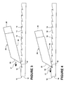
- a skiving blade 20 may be used in forming a shaving 30 ( Figure 5 ) on the metal body 10.
- the acute ledge 18 may be directed toward a direction of advancement, illustrated as arrow 21, of the skiving blade 20.
- the skiving blade 20 may be introduced into one of the nicks 12, preferably a nick towards the first end 16, as shown in Figure 4 .
- the skiving blade 20 may have a leading edge 22 and a bottom edge 24. It is contemplated that the skiving blade 20 may be introduced into the nick 12 at an angle such that the bottom edge 24 of the skiving blade 20 is at an angle with respect to the surface 14 of the metal body 10.
- the skiving blade 20 may be operably coupled to a cutter backing block 26 or other machine which may apply a driving pressure to the skiving blade 20. It is contemplated that a driving pressure may be applied in any suitable manner that may exert a force on the skiving blade 20 as it is driven into the nick 12.
- the skiving blade 20 may be pushed by the cutter backing block 26 such that the skiving blade 20 may be advanced from the nick 12 into the metal body 10 thereby producing a shaving 30, which is formed at the leading edge 22 of the skiving blade 20.
- the advancement of the skiving blade 20 may be stopped while the shaving 30 is attached to the metal body 10 such that the shaving 30 remains attached to the metal body 10 as shown in Figure 5 . This may be done for each of the nicks 12 until a plurality of shavings 30 are formed on the metal body 10.
- nicks 12 aid in forming shavings in the form of fins.
- a finned heat exchanger may be formed according to an embodiment of the invention. Such a finned heat exchanger may be used in any applicable environment including by way of non-limiting example on a jet engine, which produces substantial amounts of heat that must be transferred away from the engine.
- a portion of a heat exchanger 40 may include a heat exchanger body 42 that may be formed from a material having a hardness greater than aluminum.
- the heat exchanger body 42 may include a first surface shown as an upper surface 44 and a second surface shown as a lower surface 46, which opposes the upper surface 44 as well as at least one fluid passage 48.
- Multiple fluid passages 48 have been illustrated as being included in the heat exchanger body 42 and it is contemplated that such fluid passages 48 may take any number of sizes and shapes to aid in transferring heat from fluid being carried within the fluid passages 48.
- multiple projections 50 may be included in the heat exchanger body 42 and may from a portion of the upper surface 44. Any number of multiple projections 50 may be included in the heat exchanger body 42 and the multiple projections 50 may take a variety of shapes and sizes including that the widths of the multiple projections 50 and their spacing may be varied. Such multiple projections 50 may be formed in any suitable manner including by way of non-limiting example that the multiple projections 50 may be ridges machined from metal base stock forming the heat exchanger body 42. More specifically, by forming multiple spaced grooves in the base stock the multiple projections 50 may be machined into the heat exchanger body 42. By way of further non-limiting example, the multiple projections 50 may be cut via an EDM wire from the heat exchanger body 42.
- nicks 52 may be formed in the upper surface 44 of the heat exchanger body 42. More specifically, a plurality of nicks 52 are illustrated as being formed in the multiple projections 50. The plurality of nicks 52 are illustrated as including multiple rows of nicks 12 on the multiple projections 50 and rows of nicks 12 along the length of each the multiple projections 50. In the instant illustration rows of nicks 12 are illustrated as being along all of the multiple projections 50 for a majority of the length of multiple projections 50.
- the nicks 52 have been illustrated as a recess having an acute ledge as with the embodiments described above; however, it will be understood that the nicks 52 may be formed in any number of suitable shapes and dimensions.
- Fins 54 may be formed by introducing a skiving blade (not shown) into the nick 52 and advancing the skiving blade from the nick 52 into the material forming the heat exchanger body 42 such that the fins 54 remain attached to the heat exchanger body 42 as shown in Figure 7 . If the multiple projections 50 are included in the heat exchanger body 42, the multiple projections 50 may permit the formation of discrete fins 54 during skiving, which further promotes improved airflow mixing. After the fins 54 have been formed the heat exchanger body 42 may be trimmed in any suitable way such that at least a section of a heat exchanger 40 may be formed.
- the section of heat exchanger 40 may be shaped and combined in any suitable manner with additional sections of any suitable shape and size such that a heat exchanger or heat exchanger assembly of varying proportions may be made and may be used in a variety of different applications including by way of non-limiting example that such heat exchangers may be used with a variety of different engines.
- fluid may be passed through the fluid passages 48 and heat from the fluid may be dissipated through the fins 54 to air flowing by the fins 54.
- a heat exchanger 40 having skived fins 54 may be formed from a heat exchanger body 42 formed from a material having a hardness greater than that of aluminum.
- the above described embodiments provide for a variety of benefits including that shavings and fins may be created in harder metal materials, which may be needed for various applications.
- the above described embodiments may be more affordable, repeatable, and more reliable methods of producing shavings and fins on a hard metal material as the nicks provide an entry point for the cutter into the significantly harder material, which allows for predictable fin geometry at predictable spacing.
- the nicks also reduce the load on the skiving blade, thereby increasing the life of the skiving blade as well as the life of the cutter.
- the fins may be created with the size and uniformity desired and may be grouped together in a pattern that increases the surface area and allows for enhanced airflow mixing.
Landscapes
- Engineering & Computer Science (AREA)
- Mechanical Engineering (AREA)
- Physics & Mathematics (AREA)
- Thermal Sciences (AREA)
- General Engineering & Computer Science (AREA)
- Cutting Tools, Boring Holders, And Turrets (AREA)
- Lubricants (AREA)
- Gear Processing (AREA)
- Cooling Or The Like Of Semiconductors Or Solid State Devices (AREA)
Description
- Skiving may be generally used to produce a series of very fine integrated shavings on a metal body and the shavings may all have generally the same shape and size. For example, a heat exchanger manufacturer may use the skiving technique to create metal fins where the fin of the heat exchanger then provides a way to transfer heat from one medium to another. Integral fins formed from the parent material have a significantly higher heat transfer coefficient versus fins which may be brazed or otherwise attached to the metal body. The fins of such heat exchangers provide large surface areas required for transferring heat to the surrounding air. Usually such fins are skived out of a single block of metal such as copper or aluminum, which are materials currently used on low temperature applications.
-
JP 54-68554 - In one aspect, a method of skiving metal using a skiving blade is provided in accordance with claim 1 herein.
- In another aspect, a method of forming fins in a heat exchanger is provided in accordance with claim 13 herein.
- In the drawings:
-
Figure 1 is a schematic perspective view illustrating uneven shavings and uneven spacing between shavings which embodiments of the invention overcome; -
Figure 2A is a schematic side view illustrating a metal body with nicks formed in a surface of the metal body according to an embodiment of the invention; -
Figure 2B is a schematic perspective view illustrating the metal body ofFigure 2A ; -
Figure 3 is a schematic side view illustrating the metal body ofFigure 2A with a skiving blade which may be used according to an embodiment of the invention; -
Figure 4 is a schematic side view illustrating the metal body and skiving blade of -
Figure 3 with the skiving blade being introduced into a nick according to an embodiment of the invention; -
Figure 5 is a schematic side view illustrating an advancement of the skiving blade from the nick to form a shaving in the metal body ofFigure 3 according to an embodiment of the invention; -
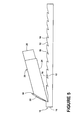
Figure 6 is a perspective view of a metal body of a heat exchanger with rows of nicks formed according to yet another embodiment of the invention; and -
Figure 7 is a perspective view of the metal body ofFigure 6 wherein fins have been formed according to a further embodiment of the invention. - While aluminum and copper are materials that are often used in skiving, especially for heat exchangers, it is considered that such materials may not be suitable for various applications and environments wherein higher-temperature materials must be used. For example, in an environment such as a jet engine, where temperatures exceed the melting point of aluminum and copper, a nearly pure nickel material, such as nickel 201, or some alloys of nickel may be desired as it has a high heat transfer coefficient and is suitable for such an environment. However, because nickel and its relevant high-temperature alloys are relatively hard materials, much harder than aluminum and copper, it is also difficult to skive and currently known skiving techniques do not result in uniform shavings that are repeatable.
-
Figure 1 illustrates that in nickel or a similarlyhard metal material 2 that is worked according to current skiving practices, theshavings 4 that are formed are very irregular both in size and in spacing. Further, a cutting tool (not shown) used for forming theshavings 4 will not have a long life because the cutting tool will skate along the surface 6 of thehard metal material 2 until enough pressure is built up at the nose of the cutting tool to enter into thehard metal material 2. This excess pressure causes the cutting tool nose to wear more quickly, and puts a larger bending load on the cutting tool nose, which in turn can lead to early fatigue of the cutting tool. - The embodiments of the methods of the invention allow for the skiving of uniform shavings on a metal material having a hardness greater than aluminum. By way of non-limiting examples, such a metal may include nickel or a nickel alloy. It will be understood that such materials are exemplary and that other materials having a hardness greater than aluminum may also be used according to the embodiments of the invention. For example, a method of skiving metal having a hardness greater than aluminum, including a
metal body 10, according to one embodiment of the invention may include forming anick 12 in asurface 14 of themetal body 10 as shown inFigure 2A . It is contemplated that thenick 12 in thesurface 14 may be formed in any suitable manner. By way of non-limiting examples, forming thenick 12 may include etching thesurface 14, cutting thesurface 14 with an EDM wire (not shown), or cutting thesurface 14 with a dovetail type milling cutter (not shown). -
Figure 2B shows themetal body 10 in perspective; it may be understood that thenick 12 may be made along a width of themetal body 10. Forming thenick 12 may include forming a plurality ofnicks 12. Such a plurality ofnicks 12 may be in a row. Forming the plurality ofnicks 12 in a row may include forming multiple rows ofnicks 12 on the width ofmetal body 10 or may include forming multiples rows ofnicks 12 along the length of the metal body. In the instant illustration a rows ofnicks 12 is illustrated as being along a portion of the length of themetal body 10. It is contemplated that thenicks 12 may not start immediately at afirst end 16 of the metal body so that there is material to be skived between thefirst nick 12 and thefirst end 16. The distance or pitch between nicks may be set to equal the desired fin spacing. - It is also contemplated that the
nicks 12 may take a variety of shapes and cross-sections depending upon the material forming themetal body 10 and depending upon the intended use of themetal body 10 once it has been skived. By way of non-limiting examples, thenick 12 may be a small indentation formed in thesurface 14, a groove formed in thesurface 14, or a deeper recess formed in thesurface 14. It has been contemplated that thenicks 12 may be on the order of 0.254mm (.010 inches) to 0.381mm (.015 inches) deep. According to the invention, forming anick 12 that is a recess includes forming anacute ledge 18 in themetal body 10 that is oriented in a certain direction with respect to thesurface 14. As shown inFigure 3 , askiving blade 20 may be used in forming a shaving 30 (Figure 5 ) on themetal body 10. Theacute ledge 18 may be directed toward a direction of advancement, illustrated asarrow 21, of theskiving blade 20. - After the desired
nicks 12 are formed, theskiving blade 20 may be introduced into one of thenicks 12, preferably a nick towards thefirst end 16, as shown inFigure 4 . The skivingblade 20 may have a leadingedge 22 and abottom edge 24. It is contemplated that theskiving blade 20 may be introduced into thenick 12 at an angle such that thebottom edge 24 of the skivingblade 20 is at an angle with respect to thesurface 14 of themetal body 10. - The skiving
blade 20 may be operably coupled to acutter backing block 26 or other machine which may apply a driving pressure to the skivingblade 20. It is contemplated that a driving pressure may be applied in any suitable manner that may exert a force on the skivingblade 20 as it is driven into thenick 12. Theskiving blade 20 may be pushed by thecutter backing block 26 such that theskiving blade 20 may be advanced from thenick 12 into themetal body 10 thereby producing a shaving 30, which is formed at the leadingedge 22 of theskiving blade 20. The advancement of the skivingblade 20 may be stopped while theshaving 30 is attached to themetal body 10 such that the shaving 30 remains attached to themetal body 10 as shown inFigure 5 . This may be done for each of thenicks 12 until a plurality ofshavings 30 are formed on themetal body 10. - It has been determined that the
nicks 12 aid in forming shavings in the form of fins. By way of non-limiting example, it is contemplated that a finned heat exchanger may be formed according to an embodiment of the invention. Such a finned heat exchanger may be used in any applicable environment including by way of non-limiting example on a jet engine, which produces substantial amounts of heat that must be transferred away from the engine. - As illustrated in
Figure 6 , a portion of aheat exchanger 40 may include aheat exchanger body 42 that may be formed from a material having a hardness greater than aluminum. Theheat exchanger body 42 may include a first surface shown as anupper surface 44 and a second surface shown as alower surface 46, which opposes theupper surface 44 as well as at least onefluid passage 48.Multiple fluid passages 48 have been illustrated as being included in theheat exchanger body 42 and it is contemplated thatsuch fluid passages 48 may take any number of sizes and shapes to aid in transferring heat from fluid being carried within thefluid passages 48. - It is contemplated that
multiple projections 50 may be included in theheat exchanger body 42 and may from a portion of theupper surface 44. Any number ofmultiple projections 50 may be included in theheat exchanger body 42 and themultiple projections 50 may take a variety of shapes and sizes including that the widths of themultiple projections 50 and their spacing may be varied. Suchmultiple projections 50 may be formed in any suitable manner including by way of non-limiting example that themultiple projections 50 may be ridges machined from metal base stock forming theheat exchanger body 42. More specifically, by forming multiple spaced grooves in the base stock themultiple projections 50 may be machined into theheat exchanger body 42. By way of further non-limiting example, themultiple projections 50 may be cut via an EDM wire from theheat exchanger body 42. - As with the above described embodiments,
nicks 52 may be formed in theupper surface 44 of theheat exchanger body 42. More specifically, a plurality ofnicks 52 are illustrated as being formed in themultiple projections 50. The plurality ofnicks 52 are illustrated as including multiple rows ofnicks 12 on themultiple projections 50 and rows ofnicks 12 along the length of each themultiple projections 50. In the instant illustration rows ofnicks 12 are illustrated as being along all of themultiple projections 50 for a majority of the length ofmultiple projections 50. Thenicks 52 have been illustrated as a recess having an acute ledge as with the embodiments described above; however, it will be understood that thenicks 52 may be formed in any number of suitable shapes and dimensions. -
Fins 54 may be formed by introducing a skiving blade (not shown) into thenick 52 and advancing the skiving blade from thenick 52 into the material forming theheat exchanger body 42 such that thefins 54 remain attached to theheat exchanger body 42 as shown inFigure 7 . If themultiple projections 50 are included in theheat exchanger body 42, themultiple projections 50 may permit the formation ofdiscrete fins 54 during skiving, which further promotes improved airflow mixing. After thefins 54 have been formed theheat exchanger body 42 may be trimmed in any suitable way such that at least a section of aheat exchanger 40 may be formed. The section ofheat exchanger 40 may be shaped and combined in any suitable manner with additional sections of any suitable shape and size such that a heat exchanger or heat exchanger assembly of varying proportions may be made and may be used in a variety of different applications including by way of non-limiting example that such heat exchangers may be used with a variety of different engines. During operation, fluid may be passed through thefluid passages 48 and heat from the fluid may be dissipated through thefins 54 to air flowing by thefins 54. In this manner aheat exchanger 40 having skivedfins 54 may be formed from aheat exchanger body 42 formed from a material having a hardness greater than that of aluminum. - The above described embodiments provide for a variety of benefits including that shavings and fins may be created in harder metal materials, which may be needed for various applications. The above described embodiments may be more affordable, repeatable, and more reliable methods of producing shavings and fins on a hard metal material as the nicks provide an entry point for the cutter into the significantly harder material, which allows for predictable fin geometry at predictable spacing. The nicks also reduce the load on the skiving blade, thereby increasing the life of the skiving blade as well as the life of the cutter. The fins may be created with the size and uniformity desired and may be grouped together in a pattern that increases the surface area and allows for enhanced airflow mixing.
- This written description uses examples to disclose the invention, including the best mode, and also to enable any person skilled in the art to practice the invention. The patentable scope of the invention is defined by the claims, and may include other examples that occur to those skilled in the art.
Claims (13)
- A method of skiving metal using a skiving blade, comprising:forming a nick (12) in a surface (14) of a metal material (10);introducing the skiving blade (20) into the nick (12); andadvancing the skiving blade from the nick into the metal material thereby forming a shaving (30); characterized in that:forming the nick (12) comprises forming a recess in the metal material (10), wherein forming the recess comprises forming an acute ledge (18) in the metal material directed toward a direction of advancement (21) of the skiving blade (20).
- The method of claim 1, wherein forming the nick (12) comprises cutting a nick in the metal material (10).
- The method of claim 2, wherein cutting the nick (12) comprises cutting the metal material (10) with an EDM wire.
- The method of any preceding claim, wherein forming the nick (12) comprises forming a plurality of nicks (52).
- The method of claim 4, wherein forming the plurality of nicks (52) comprises forming the nicks (12) in a row.
- The method of claim 5, wherein forming the nicks (12) in a row comprises forming multiple rows of nicks.
- The method of claim 6, wherein forming multiple rows of nicks (12) comprises forming a row of nicks on multiple projections (50) extending from the metal material (10).
- The method of claim 7, further comprising forming multiple, spaced grooves in the metal material (10) to form the multiple projections (50).
- The method of any preceding claim, wherein advancing the skiving blade (20) comprises stopping the advancing while the shaving (30) is attached to the metal material (10).
- The method of claim 9, wherein forming the shaving (30) comprises forming a fin (54) projecting from the metal material (10).
- The method of any preceding claim, wherein the metal material (10) comprises at least one of a nickel or nickel alloy.
- The method of any preceding claim, wherein the metal material (10) has a hardness greater than aluminum.
- A method of forming fins (54) in a heat exchanger (40) having a metal body (42) made from a material, using the method in accordance with any preceding claim;
wherein the surface in which the nick (12) is formed is an upper surface (44) of the metal body, the metal body further comprising at least one fluid passage therein;
wherein the advancing the skiving blade (20) from the nick into the material forms a fin (54) that remains attached to the metal body (42).
Applications Claiming Priority (1)
| Application Number | Priority Date | Filing Date | Title |
|---|---|---|---|
| US13/338,523 US8683905B2 (en) | 2011-12-28 | 2011-12-28 | Methods of skiving metal and forming a fin in a heat exchanger |
Publications (3)
| Publication Number | Publication Date |
|---|---|
| EP2610020A2 EP2610020A2 (en) | 2013-07-03 |
| EP2610020A3 EP2610020A3 (en) | 2013-09-04 |
| EP2610020B1 true EP2610020B1 (en) | 2015-10-28 |
Family
ID=47623821
Family Applications (1)
| Application Number | Title | Priority Date | Filing Date |
|---|---|---|---|
| EP12196903.4A Active EP2610020B1 (en) | 2011-12-28 | 2012-12-13 | Methods of skiving metal and forming a fin in a heat exchanger |
Country Status (4)
| Country | Link |
|---|---|
| US (1) | US8683905B2 (en) |
| EP (1) | EP2610020B1 (en) |
| JP (1) | JP6145266B2 (en) |
| CA (1) | CA2798775C (en) |
Cited By (1)
| Publication number | Priority date | Publication date | Assignee | Title |
|---|---|---|---|---|
| WO2023072982A1 (en) * | 2021-10-27 | 2023-05-04 | Te Connectivity Germany Gmbh | Contact element for the transmission of electric current, in particular high current, and method of manufacturing such a contact element |
Families Citing this family (6)
| Publication number | Priority date | Publication date | Assignee | Title |
|---|---|---|---|---|
| JP5582364B2 (en) * | 2012-02-01 | 2014-09-03 | 株式会社デンソー | PROJECTION FORMING DEVICE, PROJECTION FORMING METHOD, AND HEAT EXCHANGER |
| JP6125194B2 (en) * | 2012-10-30 | 2017-05-10 | Nok株式会社 | Method for machining seal mounting groove in metal plate |
| US9952004B2 (en) * | 2013-04-11 | 2018-04-24 | Solid State Cooling Systems | High efficiency thermal transfer plate |
| US20160040945A1 (en) * | 2014-08-07 | 2016-02-11 | Deere & Company | Heat exchanging system |
| US10253785B2 (en) | 2016-08-31 | 2019-04-09 | Unison Industries, Llc | Engine heat exchanger and method of forming |
| CN107949254A (en) * | 2017-12-15 | 2018-04-20 | 锐新昌轻合金(常熟)有限公司 | A kind of high-power teeth Radiator and its preparation method |
Citations (1)
| Publication number | Priority date | Publication date | Assignee | Title |
|---|---|---|---|---|
| JPS5395378A (en) * | 1977-03-26 | 1978-08-21 | Sumitomo Light Metal Ind | Method of forming fins on metallic tube |
Family Cites Families (26)
| Publication number | Priority date | Publication date | Assignee | Title |
|---|---|---|---|---|
| US3222764A (en) | 1962-02-28 | 1965-12-14 | Continental Can Co | Method of making articles having base layers and integral fins projecting therefrom |
| US3247583A (en) | 1962-03-21 | 1966-04-26 | Continental Can Co | Production of externally finned sheet stock |
| US3947941A (en) * | 1975-01-14 | 1976-04-06 | Peerless Of America, Incorporated | Method of making a heat exchanger |
| JPS5468554A (en) | 1977-11-11 | 1979-06-01 | Hitachi Ltd | Manufacturing of condensation heat conducting wall |
| US4337826A (en) * | 1979-02-26 | 1982-07-06 | Peerless Of America, Inc. | Heat exchangers and method of making same |
| JPS5682389A (en) * | 1979-12-11 | 1981-07-06 | Showa Alum Corp | Skive-finned tube |
| JPS60226696A (en) | 1984-04-24 | 1985-11-11 | Mitsubishi Heavy Ind Ltd | Finned heat transfer pipe and manufacture thereof |
| JPS61109627A (en) * | 1984-10-30 | 1986-05-28 | Hitachi Cable Ltd | Method for formation of evaporation heat transmission wall |
| JPH10323730A (en) * | 1997-05-26 | 1998-12-08 | Hitachi Cable Ltd | Manufacture of heat exchanger |
| JP3080919B2 (en) * | 1997-12-02 | 2000-08-28 | 中村製作所株式会社 | Radiator and method of forming the same |
| JP3755633B2 (en) * | 1998-08-12 | 2006-03-15 | 富士写真フイルム株式会社 | Magnetic tape cartridge |
| CA2262214A1 (en) * | 1999-02-18 | 2000-08-18 | Ray Arbesman | Disc brake backing plate and method and apparatus of manufacturing same |
| JP2002257489A (en) * | 2001-02-28 | 2002-09-11 | Showa Denko Kk | Finned heat transfer body and manufacturing method thereof |
| US20040140165A1 (en) | 2003-01-17 | 2004-07-22 | Nghi Pham | Backing plate with friction material retention members and method and apparatus for manufacturing same |
| EP1606077B1 (en) * | 2003-03-27 | 2008-10-29 | Edgecraft Corporation | Precision means for sharpening and creation or microblades along cutting edges |
| US20070157443A1 (en) * | 2003-05-02 | 2007-07-12 | Baldwin Gardner T | Method of attachment for a high pressure reinforced rubber hose coupling |
| US7222701B2 (en) * | 2003-06-02 | 2007-05-29 | Capital Tool & Design Limited | Backing plate with friction material retention members and method and apparatus for manufacturing same |
| US7125176B1 (en) * | 2003-09-30 | 2006-10-24 | Stafford John W | PCB with embedded optical fiber |
| WO2005108875A1 (en) * | 2004-05-11 | 2005-11-17 | Noritz Corporation | Heat exchanger and water heating device |
| JP2007003164A (en) * | 2005-06-27 | 2007-01-11 | Nakamura Mfg Co Ltd | Tabular heat pipe or vapor chamber, and its forming method |
| JP2007294554A (en) * | 2006-04-24 | 2007-11-08 | Sumitomo Electric Ind Ltd | Convex structural member |
| US7566228B2 (en) * | 2007-06-26 | 2009-07-28 | Intel Corporation | Skived electrical contact for connecting an IC device to a circuit board and method of making a contact by skiving |
| US8544330B2 (en) * | 2010-09-09 | 2013-10-01 | Kabushiki Kaisha Toshiba | Method and system for cooling an ultrasound probe |
| US9307674B2 (en) * | 2011-05-06 | 2016-04-05 | International Business Machines Corporation | Cooled electronic system with liquid-cooled cold plate and thermal spreader coupled to electronic component |
| US20130001289A1 (en) * | 2011-06-28 | 2013-01-03 | International Paper Company | Paperboard cup with moisture absorbing protection |
| TWI454334B (en) * | 2012-03-16 | 2014-10-01 | Inventec Corp | Heat exchanger and manufacture method thereof |
-
2011
- 2011-12-28 US US13/338,523 patent/US8683905B2/en active Active
-
2012
- 2012-12-13 CA CA2798775A patent/CA2798775C/en not_active Expired - Fee Related
- 2012-12-13 EP EP12196903.4A patent/EP2610020B1/en active Active
- 2012-12-25 JP JP2012280442A patent/JP6145266B2/en active Active
Patent Citations (1)
| Publication number | Priority date | Publication date | Assignee | Title |
|---|---|---|---|---|
| JPS5395378A (en) * | 1977-03-26 | 1978-08-21 | Sumitomo Light Metal Ind | Method of forming fins on metallic tube |
Cited By (1)
| Publication number | Priority date | Publication date | Assignee | Title |
|---|---|---|---|---|
| WO2023072982A1 (en) * | 2021-10-27 | 2023-05-04 | Te Connectivity Germany Gmbh | Contact element for the transmission of electric current, in particular high current, and method of manufacturing such a contact element |
Also Published As
| Publication number | Publication date |
|---|---|
| CA2798775A1 (en) | 2013-06-28 |
| EP2610020A2 (en) | 2013-07-03 |
| EP2610020A3 (en) | 2013-09-04 |
| US8683905B2 (en) | 2014-04-01 |
| US20130167704A1 (en) | 2013-07-04 |
| JP6145266B2 (en) | 2017-06-07 |
| JP2013139080A (en) | 2013-07-18 |
| CA2798775C (en) | 2019-01-15 |
Similar Documents
| Publication | Publication Date | Title |
|---|---|---|
| EP2610020B1 (en) | Methods of skiving metal and forming a fin in a heat exchanger | |
| US10960502B2 (en) | Metal-cutting tool, in particular a reaming tool and method of making the same | |
| BRPI0211407B1 (en) | Composite utility knife blade, plurality of composite utility knife blades and method of manufacturing such a blade. | |
| CA2858600C (en) | Methods for forming a heat exchanger and portions thereof | |
| US10065250B2 (en) | Drill and method of drilling a hole | |
| CN112676620B (en) | Rotary cutting tool and use thereof | |
| US10661362B2 (en) | Fluted cutting tool configuration and method therefor | |
| CN103732932A (en) | Sliding member, plain half bearing using same, and manufacturing method for plain half bearing | |
| ES2405301T3 (en) | Method for reducing shear and shear losses in the laminate of already installed plates | |
| CA2786394A1 (en) | Method for milling a blank in the production of a turbine blade | |
| Tang et al. | Burr formation in milling cross-connected microchannels with a thin slotting cutter | |
| CN110740830A (en) | Saw blade and method for manufacturing the same | |
| JP2005142247A (en) | Radiator and manufacturing method therefor | |
| JP2014226737A (en) | Cutting-processing method | |
| US11278974B2 (en) | Harvesting knife and method for the production thereof | |
| JP2012501858A (en) | Band saw blade with small protrusions | |
| US20180221967A1 (en) | Drilling system and drill insert and methods for hole drilling | |
| US9895757B2 (en) | Reamer | |
| EP2604360A2 (en) | Heat exchanger with fins and method for forming same | |
| Mohid et al. | Chip pattern, burr and surface roughness in laser assisted micro milling of Ti6Al4V using micro ball end mill | |
| JP2000288654A (en) | Die-less punching method of pipe | |
| JP6335654B2 (en) | Fine tool | |
| JP2009220261A (en) | Helical broach for internal gear machining, and broaching method | |
| JP2009290014A (en) | Method of manufacturing heat sink | |
| KR20150088666A (en) | Piercing punch structure for press |
Legal Events
| Date | Code | Title | Description |
|---|---|---|---|
| PUAI | Public reference made under article 153(3) epc to a published international application that has entered the european phase |
Free format text: ORIGINAL CODE: 0009012 |
|
| AK | Designated contracting states |
Kind code of ref document: A2 Designated state(s): AL AT BE BG CH CY CZ DE DK EE ES FI FR GB GR HR HU IE IS IT LI LT LU LV MC MK MT NL NO PL PT RO RS SE SI SK SM TR |
|
| AX | Request for extension of the european patent |
Extension state: BA ME |
|
| PUAL | Search report despatched |
Free format text: ORIGINAL CODE: 0009013 |
|
| AK | Designated contracting states |
Kind code of ref document: A3 Designated state(s): AL AT BE BG CH CY CZ DE DK EE ES FI FR GB GR HR HU IE IS IT LI LT LU LV MC MK MT NL NO PL PT RO RS SE SI SK SM TR |
|
| AX | Request for extension of the european patent |
Extension state: BA ME |
|
| RIC1 | Information provided on ipc code assigned before grant |
Ipc: H04N 5/445 20110101ALI20130730BHEP Ipc: H04N 5/00 20110101AFI20130730BHEP Ipc: H04N 21/436 20110101ALI20130730BHEP Ipc: H04N 21/462 20110101ALI20130730BHEP |
|
| 17P | Request for examination filed |
Effective date: 20140304 |
|
| RBV | Designated contracting states (corrected) |
Designated state(s): AL AT BE BG CH CY CZ DE DK EE ES FI FR GB GR HR HU IE IS IT LI LT LU LV MC MK MT NL NO PL PT RO RS SE SI SK SM TR |
|
| REG | Reference to a national code |
Ref country code: DE Ref legal event code: R079 Ref document number: 602012011936 Country of ref document: DE Free format text: PREVIOUS MAIN CLASS: B21J0005120000 Ipc: H04N0005000000 |
|
| GRAP | Despatch of communication of intention to grant a patent |
Free format text: ORIGINAL CODE: EPIDOSNIGR1 |
|
| RIC1 | Information provided on ipc code assigned before grant |
Ipc: H04N 5/445 20110101ALI20150527BHEP Ipc: H04N 5/00 20110101AFI20150527BHEP Ipc: H04N 21/436 20110101ALI20150527BHEP Ipc: H04N 21/462 20110101ALI20150527BHEP |
|
| INTG | Intention to grant announced |
Effective date: 20150630 |
|
| GRAS | Grant fee paid |
Free format text: ORIGINAL CODE: EPIDOSNIGR3 |
|
| GRAA | (expected) grant |
Free format text: ORIGINAL CODE: 0009210 |
|
| AK | Designated contracting states |
Kind code of ref document: B1 Designated state(s): AL AT BE BG CH CY CZ DE DK EE ES FI FR GB GR HR HU IE IS IT LI LT LU LV MC MK MT NL NO PL PT RO RS SE SI SK SM TR |
|
| REG | Reference to a national code |
Ref country code: GB Ref legal event code: FG4D |
|
| REG | Reference to a national code |
Ref country code: CH Ref legal event code: EP |
|
| REG | Reference to a national code |
Ref country code: AT Ref legal event code: REF Ref document number: 758464 Country of ref document: AT Kind code of ref document: T Effective date: 20151115 |
|
| REG | Reference to a national code |
Ref country code: IE Ref legal event code: FG4D |
|
| REG | Reference to a national code |
Ref country code: DE Ref legal event code: R096 Ref document number: 602012011936 Country of ref document: DE |
|
| REG | Reference to a national code |
Ref country code: FR Ref legal event code: PLFP Year of fee payment: 4 |
|
| REG | Reference to a national code |
Ref country code: LT Ref legal event code: MG4D |
|
| REG | Reference to a national code |
Ref country code: NL Ref legal event code: MP Effective date: 20151028 |
|
| REG | Reference to a national code |
Ref country code: AT Ref legal event code: MK05 Ref document number: 758464 Country of ref document: AT Kind code of ref document: T Effective date: 20151028 |
|
| PG25 | Lapsed in a contracting state [announced via postgrant information from national office to epo] |
Ref country code: IS Free format text: LAPSE BECAUSE OF FAILURE TO SUBMIT A TRANSLATION OF THE DESCRIPTION OR TO PAY THE FEE WITHIN THE PRESCRIBED TIME-LIMIT Effective date: 20160228 Ref country code: ES Free format text: LAPSE BECAUSE OF FAILURE TO SUBMIT A TRANSLATION OF THE DESCRIPTION OR TO PAY THE FEE WITHIN THE PRESCRIBED TIME-LIMIT Effective date: 20151028 Ref country code: LT Free format text: LAPSE BECAUSE OF FAILURE TO SUBMIT A TRANSLATION OF THE DESCRIPTION OR TO PAY THE FEE WITHIN THE PRESCRIBED TIME-LIMIT Effective date: 20151028 Ref country code: NL Free format text: LAPSE BECAUSE OF FAILURE TO SUBMIT A TRANSLATION OF THE DESCRIPTION OR TO PAY THE FEE WITHIN THE PRESCRIBED TIME-LIMIT Effective date: 20151028 Ref country code: HR Free format text: LAPSE BECAUSE OF FAILURE TO SUBMIT A TRANSLATION OF THE DESCRIPTION OR TO PAY THE FEE WITHIN THE PRESCRIBED TIME-LIMIT Effective date: 20151028 Ref country code: IT Free format text: LAPSE BECAUSE OF FAILURE TO SUBMIT A TRANSLATION OF THE DESCRIPTION OR TO PAY THE FEE WITHIN THE PRESCRIBED TIME-LIMIT Effective date: 20151028 Ref country code: NO Free format text: LAPSE BECAUSE OF FAILURE TO SUBMIT A TRANSLATION OF THE DESCRIPTION OR TO PAY THE FEE WITHIN THE PRESCRIBED TIME-LIMIT Effective date: 20160128 |
|
| PG25 | Lapsed in a contracting state [announced via postgrant information from national office to epo] |
Ref country code: FI Free format text: LAPSE BECAUSE OF FAILURE TO SUBMIT A TRANSLATION OF THE DESCRIPTION OR TO PAY THE FEE WITHIN THE PRESCRIBED TIME-LIMIT Effective date: 20151028 Ref country code: BE Free format text: LAPSE BECAUSE OF NON-PAYMENT OF DUE FEES Effective date: 20151231 Ref country code: SE Free format text: LAPSE BECAUSE OF FAILURE TO SUBMIT A TRANSLATION OF THE DESCRIPTION OR TO PAY THE FEE WITHIN THE PRESCRIBED TIME-LIMIT Effective date: 20151028 Ref country code: LV Free format text: LAPSE BECAUSE OF FAILURE TO SUBMIT A TRANSLATION OF THE DESCRIPTION OR TO PAY THE FEE WITHIN THE PRESCRIBED TIME-LIMIT Effective date: 20151028 Ref country code: PL Free format text: LAPSE BECAUSE OF FAILURE TO SUBMIT A TRANSLATION OF THE DESCRIPTION OR TO PAY THE FEE WITHIN THE PRESCRIBED TIME-LIMIT Effective date: 20151028 Ref country code: AT Free format text: LAPSE BECAUSE OF FAILURE TO SUBMIT A TRANSLATION OF THE DESCRIPTION OR TO PAY THE FEE WITHIN THE PRESCRIBED TIME-LIMIT Effective date: 20151028 Ref country code: RS Free format text: LAPSE BECAUSE OF FAILURE TO SUBMIT A TRANSLATION OF THE DESCRIPTION OR TO PAY THE FEE WITHIN THE PRESCRIBED TIME-LIMIT Effective date: 20151028 Ref country code: GR Free format text: LAPSE BECAUSE OF FAILURE TO SUBMIT A TRANSLATION OF THE DESCRIPTION OR TO PAY THE FEE WITHIN THE PRESCRIBED TIME-LIMIT Effective date: 20160129 Ref country code: PT Free format text: LAPSE BECAUSE OF FAILURE TO SUBMIT A TRANSLATION OF THE DESCRIPTION OR TO PAY THE FEE WITHIN THE PRESCRIBED TIME-LIMIT Effective date: 20160229 |
|
| PG25 | Lapsed in a contracting state [announced via postgrant information from national office to epo] |
Ref country code: CZ Free format text: LAPSE BECAUSE OF FAILURE TO SUBMIT A TRANSLATION OF THE DESCRIPTION OR TO PAY THE FEE WITHIN THE PRESCRIBED TIME-LIMIT Effective date: 20151028 Ref country code: LU Free format text: LAPSE BECAUSE OF FAILURE TO SUBMIT A TRANSLATION OF THE DESCRIPTION OR TO PAY THE FEE WITHIN THE PRESCRIBED TIME-LIMIT Effective date: 20151213 Ref country code: MC Free format text: LAPSE BECAUSE OF FAILURE TO SUBMIT A TRANSLATION OF THE DESCRIPTION OR TO PAY THE FEE WITHIN THE PRESCRIBED TIME-LIMIT Effective date: 20151028 |
|
| REG | Reference to a national code |
Ref country code: CH Ref legal event code: PL Ref country code: DE Ref legal event code: R097 Ref document number: 602012011936 Country of ref document: DE |
|
| PG25 | Lapsed in a contracting state [announced via postgrant information from national office to epo] |
Ref country code: SK Free format text: LAPSE BECAUSE OF FAILURE TO SUBMIT A TRANSLATION OF THE DESCRIPTION OR TO PAY THE FEE WITHIN THE PRESCRIBED TIME-LIMIT Effective date: 20151028 Ref country code: RO Free format text: LAPSE BECAUSE OF FAILURE TO SUBMIT A TRANSLATION OF THE DESCRIPTION OR TO PAY THE FEE WITHIN THE PRESCRIBED TIME-LIMIT Effective date: 20151028 Ref country code: SM Free format text: LAPSE BECAUSE OF FAILURE TO SUBMIT A TRANSLATION OF THE DESCRIPTION OR TO PAY THE FEE WITHIN THE PRESCRIBED TIME-LIMIT Effective date: 20151028 Ref country code: EE Free format text: LAPSE BECAUSE OF FAILURE TO SUBMIT A TRANSLATION OF THE DESCRIPTION OR TO PAY THE FEE WITHIN THE PRESCRIBED TIME-LIMIT Effective date: 20151028 Ref country code: DK Free format text: LAPSE BECAUSE OF FAILURE TO SUBMIT A TRANSLATION OF THE DESCRIPTION OR TO PAY THE FEE WITHIN THE PRESCRIBED TIME-LIMIT Effective date: 20151028 |
|
| PLBE | No opposition filed within time limit |
Free format text: ORIGINAL CODE: 0009261 |
|
| STAA | Information on the status of an ep patent application or granted ep patent |
Free format text: STATUS: NO OPPOSITION FILED WITHIN TIME LIMIT |
|
| REG | Reference to a national code |
Ref country code: IE Ref legal event code: MM4A |
|
| 26N | No opposition filed |
Effective date: 20160729 |
|
| PG25 | Lapsed in a contracting state [announced via postgrant information from national office to epo] |
Ref country code: LI Free format text: LAPSE BECAUSE OF NON-PAYMENT OF DUE FEES Effective date: 20151231 Ref country code: IE Free format text: LAPSE BECAUSE OF NON-PAYMENT OF DUE FEES Effective date: 20151213 Ref country code: CH Free format text: LAPSE BECAUSE OF NON-PAYMENT OF DUE FEES Effective date: 20151231 |
|
| PG25 | Lapsed in a contracting state [announced via postgrant information from national office to epo] |
Ref country code: SI Free format text: LAPSE BECAUSE OF FAILURE TO SUBMIT A TRANSLATION OF THE DESCRIPTION OR TO PAY THE FEE WITHIN THE PRESCRIBED TIME-LIMIT Effective date: 20151028 |
|
| REG | Reference to a national code |
Ref country code: FR Ref legal event code: PLFP Year of fee payment: 5 |
|
| PG25 | Lapsed in a contracting state [announced via postgrant information from national office to epo] |
Ref country code: BE Free format text: LAPSE BECAUSE OF FAILURE TO SUBMIT A TRANSLATION OF THE DESCRIPTION OR TO PAY THE FEE WITHIN THE PRESCRIBED TIME-LIMIT Effective date: 20151028 |
|
| PG25 | Lapsed in a contracting state [announced via postgrant information from national office to epo] |
Ref country code: BG Free format text: LAPSE BECAUSE OF FAILURE TO SUBMIT A TRANSLATION OF THE DESCRIPTION OR TO PAY THE FEE WITHIN THE PRESCRIBED TIME-LIMIT Effective date: 20151028 Ref country code: HU Free format text: LAPSE BECAUSE OF FAILURE TO SUBMIT A TRANSLATION OF THE DESCRIPTION OR TO PAY THE FEE WITHIN THE PRESCRIBED TIME-LIMIT; INVALID AB INITIO Effective date: 20121213 |
|
| PG25 | Lapsed in a contracting state [announced via postgrant information from national office to epo] |
Ref country code: CY Free format text: LAPSE BECAUSE OF FAILURE TO SUBMIT A TRANSLATION OF THE DESCRIPTION OR TO PAY THE FEE WITHIN THE PRESCRIBED TIME-LIMIT Effective date: 20151028 |
|
| PG25 | Lapsed in a contracting state [announced via postgrant information from national office to epo] |
Ref country code: MT Free format text: LAPSE BECAUSE OF FAILURE TO SUBMIT A TRANSLATION OF THE DESCRIPTION OR TO PAY THE FEE WITHIN THE PRESCRIBED TIME-LIMIT Effective date: 20151028 |
|
| REG | Reference to a national code |
Ref country code: FR Ref legal event code: PLFP Year of fee payment: 6 |
|
| PG25 | Lapsed in a contracting state [announced via postgrant information from national office to epo] |
Ref country code: TR Free format text: LAPSE BECAUSE OF FAILURE TO SUBMIT A TRANSLATION OF THE DESCRIPTION OR TO PAY THE FEE WITHIN THE PRESCRIBED TIME-LIMIT Effective date: 20151028 Ref country code: MK Free format text: LAPSE BECAUSE OF FAILURE TO SUBMIT A TRANSLATION OF THE DESCRIPTION OR TO PAY THE FEE WITHIN THE PRESCRIBED TIME-LIMIT Effective date: 20151028 |
|
| PG25 | Lapsed in a contracting state [announced via postgrant information from national office to epo] |
Ref country code: AL Free format text: LAPSE BECAUSE OF FAILURE TO SUBMIT A TRANSLATION OF THE DESCRIPTION OR TO PAY THE FEE WITHIN THE PRESCRIBED TIME-LIMIT Effective date: 20151028 |
|
| PGFP | Annual fee paid to national office [announced via postgrant information from national office to epo] |
Ref country code: DE Payment date: 20191119 Year of fee payment: 8 |
|
| REG | Reference to a national code |
Ref country code: DE Ref legal event code: R119 Ref document number: 602012011936 Country of ref document: DE |
|
| PG25 | Lapsed in a contracting state [announced via postgrant information from national office to epo] |
Ref country code: DE Free format text: LAPSE BECAUSE OF NON-PAYMENT OF DUE FEES Effective date: 20210701 |
|
| P01 | Opt-out of the competence of the unified patent court (upc) registered |
Effective date: 20230418 |
|
| PGFP | Annual fee paid to national office [announced via postgrant information from national office to epo] |
Ref country code: GB Payment date: 20231121 Year of fee payment: 12 |
|
| PGFP | Annual fee paid to national office [announced via postgrant information from national office to epo] |
Ref country code: FR Payment date: 20231122 Year of fee payment: 12 |