EP2609968A2 - Verfahren für einen Brandentlüftungsfunktionstest und Testvorrichtung - Google Patents
Verfahren für einen Brandentlüftungsfunktionstest und Testvorrichtung Download PDFInfo
- Publication number
- EP2609968A2 EP2609968A2 EP11466041.8A EP11466041A EP2609968A2 EP 2609968 A2 EP2609968 A2 EP 2609968A2 EP 11466041 A EP11466041 A EP 11466041A EP 2609968 A2 EP2609968 A2 EP 2609968A2
- Authority
- EP
- European Patent Office
- Prior art keywords
- aerosol
- fire ventilation
- space
- fire
- function test
- Prior art date
- Legal status (The legal status is an assumption and is not a legal conclusion. Google has not performed a legal analysis and makes no representation as to the accuracy of the status listed.)
- Withdrawn
Links
Images



Classifications
-
- A—HUMAN NECESSITIES
- A62—LIFE-SAVING; FIRE-FIGHTING
- A62C—FIRE-FIGHTING
- A62C37/00—Control of fire-fighting equipment
- A62C37/50—Testing or indicating devices for determining the state of readiness of the equipment
-
- A—HUMAN NECESSITIES
- A62—LIFE-SAVING; FIRE-FIGHTING
- A62C—FIRE-FIGHTING
- A62C99/00—Subject matter not provided for in other groups of this subclass
- A62C99/0081—Training methods or equipment for fire-fighting
Definitions
- the invention relates to the field of fire safety and fire technology.
- a new method of fire ventilation function test and a device specifically arranged for carrying out this method of verification test of the fire ventilation functionality are invented.
- Fire safety of large complexes such as manufacturing objects, industrial as well as non-industrial halls, tunnels of motorway and road corridors, metro and other constructional objects, is determined most of all theoretically by means of calculation during engineering design of their construction, based on expert science and technology knowledge.
- Requirements for structural design of objects, used materials, and means of fire ignition and propagation prevention are specified in the project of fire safety of buildings.
- Means of detection of possible fire, means of fire ventilation of the object, air-handling, escape routes etc. are also specified.
- Device for heat and smoke removal, that is the fire ventilation is one of the basic fire safety devices.
- a method is used in which a generator of a real smoke like the true fume during a fire is placed into the tested area, whereupon the movement and concentration of the resulting smoke is monitored in the course of operation of the fire ventilation means.
- Real smoke is usually obtained by combustion of gasoline and/or diesel fuel, solid combustible materials, or other combustible materials that are known as usual materials burning in fires.
- the advantage of this method is that it allows visualization, i.e. recording that can be watched with the possibility of monitoring and reviewing the flow of air masses with smoke fumes, and it also gives the possibility of measuring the optical density of smoke and thus monitoring of the smoke stratification.
- Hot smoke is produced by combustion of 5 litres of gasoline or 20 litres of diesel fuel in a steel container on the area of 1 m 2 , the passage of the hot smoke through the tested space is recorded on a video and simultaneously the optical density of the smoke is measured at different heights.
- the time of exchange of gases and polluted air in dependence on the volume exchange of air masses and on the smoke optical density is monitored and measured, and then evaluated.
- this test In addition to the failure to simulate the amount of smoke corresponding to the real fire, this test also generates toxic and aggressive gaseous combustion products that degrade the technological equipment of the tunnel and constitute the need for repairs and replacements, and also imply the need to clean the space of the tunnel, which, in addition to high costs, results in the necessity of long-term shutdown of tunnels and complicates traffic and transportation.
- Standard smoke cartridge is used as a source for the monitored cloud, or only water vapour is used.
- the product of smoke cartridge is a mixture of gases.
- Water vapour is also a gaseous phase only.
- the resulting cloud is based on just harmless gaseous substances and it is visible.
- the advantage of this method is the absence of toxic fumes and the possibility of recording and observation of movement of the developed cloud.
- it is impossible to achieve the dynamics of behaviour of a real smoke during a fire in terms of stratification, or even approximate to it, mainly because of the absence of thermal dynamics of solid particles, whose presence would make it possible to measure optical density in a way comparable with the smoke in a real fire. Consequence of this fact is the inability to fully evaluate correct functioning of fire ventilation.
- a new method of fire ventilation function test is invented, according to which a generator of non-toxic aerosol simulating combustion smoke products is placed into the tested space and the generator is equipped with a predetermined number of compositions, these compositions are activated and then propagation of the generated non-toxic aerosol is monitored, while a video is recorded and measurements of values necessary for evaluation of functionality of fire ventilation in the given space are performed, and finally the observed measurements are compared with values of a real smoke, for instance the smoke produced during combustion of gasoline and diesel fuel, measured in a test space.
- a non-toxic aerosol is generated in the generator and the aerosol formed at the temperature of 600 to 1300° C consists of a mixture of solid and gaseous phases, of which the solid phase consists of particles with a particle size of 1 to 5 ⁇ m based on potassium carbonate, potassium hydrogen carbonate and carbon, and the gaseous phase is a medium based on carbon dioxide, water vapours, nitrous gases, nitrogen and ammonia.
- This aerosol has extinguishing effects.
- Non-toxic aerosol is preferably generated in quantity fully corresponding to the production of real smoke during fire, i.e. 3 to 100 m 3 /s, while the specific generated quantity for individual verification test is determined in advance within the mentioned range. This is done particularly in dependence on projected parameters of the fire ventilation for the tested space, for instance at the level of the highest values permitted by the project or at the level close to these values.
- the values mentioned below are monitored in the course of the test. These are the speed of the aerosol cloud movement measured by means of monitoring the flow of air including the contained aerosol, the temperature in the area of the aerosol generator and in the space, and stratification and dispersal of the aerosol cloud by means of measurement of optical density of the aerosol. Preferably at the same time, video is also recorded that indicates the direction and flow of aerosol particles in dependence on functioning of the fire ventilation and also the time of exchange of gases and polluted air in dependence on the volume exchange of air masses and on the aerosol optical density is measured.
- the aerosol optical density is determined in the tested space during the test by means of video recording and/or by measurements at different distances from activation of compositions and in different heights. These measurements at different distances and at different height levels allow monitoring the movement and dispersal of the generated aerosol cloud.
- the tested space is equipped with air-handling equipment, it is purposeful to put into operation all or, according to the aim of the test, some of the air-handling equipment of the tested space in the course of the aerosol generation and monitoring of the aerosol propagation.
- the method is intended especially for verification whether the tested space is equipped with sufficient air-handling devices for smoke and heat removal, and for testing the quality of functionality of these devices in the given spaces.
- it is not excluded to use it to test even spaces that are lacking air-handling devices for the time being, which is eligible for instance in the case of older constructional objects and in objects with natural ventilation.
- the generator of non-toxic aerosol is still before activation of the contained composition placed on at least one carrier mounted on or behind a vehicle, and that in such position and so open to the surrounding space that the generated aerosol can freely propagate to the surrounding space.
- This propagation has usually a shape of a cloud that is moving in the tested space and diffuses here or is removed with the help of the tested air-handling devices and/or natural ventilation.
- one-shot or sequential activation is performed by firing the compositions. Activation can take place statically, i.e. with leaving the source of aerosol immovable at the site of the composition activation until diffusion or removal of the aerosol cloud.
- the vehicle can move inside the tested space, for instance by driving across the tested space during and/or after activation of the composition, while a mobile video device such as another vehicle with a video camera is moving in the area of the edge of the generated aerosol cloud and recording a video enabling to visualize the course of the test.
- a mobile video device such as another vehicle with a video camera is moving in the area of the edge of the generated aerosol cloud and recording a video enabling to visualize the course of the test.
- the invention solves also design of the device suitable for carrying out the invented method of the fire ventilation function test according to the invention.
- the device includes a generator containing vessels of non-inflammable solid material, e.g. steel, with inner cavity that are at least partially filled with combustible composition.
- the essence of the new solution is that the compositions in the vessels are creating the source of non-toxic aerosol imitating with its appearance, optical density, stratification, and the manner of movement authentically the combustion products, i.e. the aerosol consisting of solid particles with the particle size of 1 to 5 ⁇ m and non-toxic gaseous substances.
- No cooler is contained; the vessel contains only a firing device in addition to the composition, and only a free space is in vessels above the composition with the firing device.
- these vessels are in the number of 4 to 10 pieces placed in at least one storage device of non-inflammable solid material such as steel, and here equipped with a common perforated cover.
- the storage device for the vessels is preferably in a shape of a stand with its upper part created as a bed for the vessels and under this bed, a base with at least one inner cavity for necessary electric elements of the firing device is located.
- the bed is preferably equipped with at least one opening and the inner cavity of the base is through, connected to this opening, while the base is equipped with at least one element stabilizing its position relative to the support.
- a support plate with holes and fixing bolts or rivets created at the bottom, or welded strips of material, an extended and bent wall of the base leg, welded profile, etc. can be used as the element stabilizing the position of the stand to the support.
- the stand in the number of one or more is preferably placed in a tub of non-inflammable solid material such as steel, where this tub contains at least a bottom and all-circumferential rim, while the stand is firmly, immovably fixed to the bottom of this tub.
- the tub creates bearing basis for the stands occupied or only some of them occupied with the vessels, it allows transport of compositions to the site of use and transport during use, as the case may be, and it can serve for possible supplementary flammable charge such as ethanol in case the client requires increasing of the fire effect.
- Part of the rim on one side can be extended and used for fixing the tub with stands and compositions to the site of use, for instance to the carrier, as shown hereinafter in the example of embodiment.
- the tub preferably contains one to twenty stands, while at least some of the contained stands have full bed filled with the vessels.
- the perforated cover mentioned above in the first paragraph of the device description can be in a configuration with dimensions for covering all contained stands together or for covering of each one of contained stands separately or as the case may be for covering groups of stands.
- the stands are preferably covered with the perforated cover separately one by one, which saves material in the case of incomplete occupation of the tub with the stands and facilitates manipulations connected with mounting of individual elements of the device into the whole unit.
- the tub is placed on a bearing structure of a movable device, for instance of a vehicle, freely open to the surrounding space at least in the area of the cover.
- a movable device for instance of a vehicle
- the tub with stands and compositions can be preferably fixed for instance on a trailer behind a car or on a special carrier directly on the car.
- the device created and arranged in this way can be operated without any danger by a driver present in the tested space.
- the composition preferably consists of a material from which in case of firing the composition the non-toxic aerosol is generated, solid particles of which contain a mixture of potassium carbonate, potassium hydrogen carbonate and carbon, and the gaseous phase of which contains a mixture of carbon dioxide, water vapours, nitrous gases, nitrogen, and ammonia.
- This material is known already and available on the market, but it is manufactured and used up to now for completely different purpose, i.e. as an extinguishing mixture.
- the designed technical solution according to the invention has the advantages in that it simulates the real smoke that is produced during a fire, but it is non-toxic and does not cause destruction or damage to the instrumentation and other equipment in the object due to high heat. Simulation of the real smoke from combustion of substances that are frequently the usual cause of the fire, i.e. gasoline, diesel fuel, paper, wood, solid fuels, plastics, etc. is perfect especially regarding the optical features.
- the aerosol cloud is generated that has the appearance for human eye and even for detecting device identical to the smoke during a fire, and that has also identical stratification with respect to the particle density, cloud shape, the way of movement of the cloud as well as the way and speed of diffusion.
- the said values can be visualised by means of video recording, with the possibility of subsequent and repeated reviewing and with the possibility to measure the values such as optical density in various places and heights etc.
- the figures of toxic admixtures present are below the toxicity levels stated by the standards, and thus this aerosol can be considered to be non-toxic. Because of the fact that the aerosol cloud is non-toxic and it is even dispersed in the tested space and removed from the tested space by air-handling system during the test, it is possible to perform firing of the composition on a static or moving vehicle with a driver without the risk of persons' health hazard and it is possible to perform in an ideal way a video recording during the test, for instance from a vehicle moving behind the vehicle with the composition.
- the method and device according to the invention allow finding in an optimal way the values to which the particular fire ventilation has to be set. It further allows making dispatchers familiar with a real fire, i.e. with probable direction of the fire propagation according to the place of origin and with its course. From the point of view of toxicity of substances, the concentration of toxic admixtures ranges in values in order of 100 to 600 times lower than the prescribed permissible exposure limits.
- FIG. 1 shows perspective view of an example of the device for the fire ventilation function test according to the invention
- Fig. 2 shows top plan view into the individual vessel with the composition
- Fig. 3 shows front view of the vessel when section is drawn along the line A-A indicated on the previous figure
- Fig. 4 shows perspective view of individual stand
- Fig. 5 shows front view of vertical longitudinal section drawn across the stand filled with the vessels, through the centre of the vessels
- Fig. 6 shows perspective view of the tub filled with empty stands
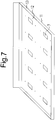
- Fig. 7 shows perspective view of the individual tub
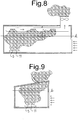
- Fig. 8 shows illustration of function of the invented device and of carrying out the method during the fire ventilation function test in a room equipped with air-handling device with a fan
- Fig. 1 shows perspective view of an example of the device for the fire ventilation function test according to the invention
- Fig. 2 shows top plan view into the individual vessel with the composition
- Fig. 3 shows front view of the vessel when section is drawn along the line A-A indicated on the previous figure
- Fig. 4 shows perspective view
- FIG. 9 shows illustration of function of the invented device and of carrying out the method during the fire ventilation function test in a room with natural ventilation by means of an air shaft
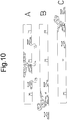
- Fig. 10A, B, C shows illustration of function of the invented device and three demonstrative variants of carrying out the method during the fire ventilation function test in a tunnel using static compositions
- Fig. 11A, B, C shows illustration of function of the invented device and three demonstrative variants of carrying out the method during the fire ventilation function test in a tunnel using mobile compositions.
- Example of the best embodiment of the invention is the device for carrying out the method of the fire ventilation function test with illustrations of its use and process during carrying out the method according to Figs. 1 to 11 .
- the core of the device for carrying out the method of the fire ventilation function test is the generator shown on Fig. 1 .
- the generator contains the source of non-toxic aerosol simulating smoke fumes created during a fire, which creates the charge in vessels 1 of non-inflammable solid material.
- vessels 1 of practical cylindrical shape has been chosen, which are made of steel and thus are having sufficient strength and mechanical durability.
- the inner cavity of the vessels 1 is only partially filed with the charge, this charge is as the aerosol source the flammable composition 2 .
- each vessel 1 placed in the generator contains only the firing device 3 with necessary electric accessories allowing firing, including electric conductors 4 in the case of wire firing.
- the vessels 1 are in the number of 4 to 10 pieces placed in storage devices in the shape of stands made of non-inflammable solid material.
- preferred chosen number of vessels 1 is six pieces per each stand, which is within the abovementioned range.
- the stands for this example of embodiment has been made of steel, however, also other suitable material can be used that ensures sufficient strength and mechanical durability for the stands.
- Figs. 4 and 5 The upper part is created by the bed 5 for placing the vessels 1 , and it has a shape of a box with a cut-out in the centre. Under this bed 5 , the base 6 is located and in this case it is arranged as a leg, but it can have also different suitable shape in other case.
- the base 6 is hollow; its inner cavity has dimensions and shape allowing placing of necessary accompanying electric elements and the firing device, electric conductors 4 in particular.
- the cut-out in the centre of the bed 5 is arranged as an admission opening 7 into the cavity of the base 6 , which is through and connected to the opening 7 .
- the base 6 is equipped with at least one element stabilizing its position to the support, in this case it is a support plate 8 created at the bottom.
- Each stand is equipped with a bolt-on perforated cover 9 covering the vessels 1 and preventing their unwanted loosening during transport to the site of use and during the aerosol generation and preventing also unwanted premature damage to the firing device 3 and possibly contained conductors 4 . Perforation of the cover 9 creates openings for escape of generated aerosol from vessels 1 into space and for creation of the aerosol cloud.
- the vessels 1 can be placed in the bed 5 of the stand together with the boxes 10 , in which they are supplied, or possibly such boxes 10 filled with vessels 1 containing the composition 2 can be prepared in advance separately and their presence facilitates manipulation during counting charges, filling of stands, and also clean-up of used vessels 1 and a trash left over later after completion of tests.
- the stands in the number of one to twenty are placed in a tub 11 of non-inflammable sufficiently strong material.
- the tub 11 is made of steel.
- the tub 11 has a bottom 12 , to which all contained stands are firmly and immovably fixed using common means of connection such as screws, bolts, rivets, or welding joints.
- a peripheral rim 13 projecting upwards is created around the bottom 12 of the tub 11 to prevent falling out of possibly broken off pieces of material and allowing placing of supplementary charge such as ethanol etc. on the client's request to increase the fire effect for instance.
- the tub 11 can have created openings 7 for electric conductors 4 , where these openings 7 are arranged so that they are linked adequately to the cavities of bases 6 and openings 7 of beds 5 of the stands. Even several tubs 11 with stands can be used for one test, according to calculated necessary dose of compositions 2 . As far as the number of vessels 1 in individual stands is concerned, it is of course significantly more economic to fill preferentially full beds 5 with the vessels 1 , with possible gathering of calculated remaining number of vessels 1 gathered into one stand, with a higher number of unused stands, rather than evenly but incompletely occupy unnecessarily high number of stands and to provide them with perforated covers 9 .
- the tub 11 can be in the number of one or more fixed on a bearing structure 14 of a movable device, for instance on a vehicle, and that in such position and place on the vehicle selected so that at least the area of each contained cover 9 shall remain freely open to the surrounding space for all the time of the test, which is necessary to prevent occurrence of any barrier to creation of cloud from the generated aerosol.
- the optimal placement is using a special bearing structure 14 custom made for this purpose and mounted at the rear side of a car, however any other suitable carrying means can be possibly chosen such as roof baggage rack on the vehicle, trailer, bowl etc.
- Angular circumferential shape of the tub 11 and other elements mentioned above is not a requirement.
- the composition 2 consists of a material generating in case of firing a non-toxic aerosol, solid particles of which contain a mixture of potassium carbonate (K 2 CO 3 ), potassium hydrogen carbonate (KHCO 3 ) and carbon (C), and the gaseous phase of which contains a mixture of carbon dioxide (CO 2 ) water vapours (H 2 O), nitrous gases (NO x ), nitrogen (N 2 ), and ammonia (NH 4 ).
- K 2 CO 3 potassium carbonate
- KHCO 3 potassium hydrogen carbonate
- CO 2 carbon dioxide
- NO x nitrous gases
- N 2 nitrogen
- ammonia NH 4
- Aerosol generated by firing this mixture can be characterised as unhealthy up to harmful, however this harmfulness does not reach such a degree that it could be considered as toxic.
- the device is designed for the new method of the fire ventilation function test according to the invention. Example performance of tests according to this method is described hereinafter. Function of the device and carrying out of the method are shown on Figs. 8 to 11 .
- Preparation for performance of the method includes at least examination of the project documentation of the tested space, ascertainment of the type, number, and location of air-handling devices and devices for smoke and heat removal, and of other devices in the tested space, finding of elements of natural ventilation, determination of shape, dimensions, and materials in the tested premises and identification of projected parameters of the fire ventilation. Further on, this preparation includes distribution of corresponding sensors and gauges in the tested space, including possible video cameras 15 unless they were already installed sooner.
- the device according to the invention equipped with calculated necessary number of vessels 1 with composition 2 is prepared in advance.
- the generator of non-toxic aerosol simulating combustion smoke products is placed into the tested space, its compositions 2 are activated and then propagation of the generated aerosol is monitored, while a video is recorded and measurements of values necessary for evaluation of functionality of fire ventilation in the given space are performed, and finally the observed measurements are compared with values of a real smoke, for instance the smoke formed during combustion of gasoline and diesel fuel, measured in a test space. On the basis of the found results, evaluation of functionality of the fire ventilation of the tested space is performed. Modern scientific and technical equipment including data control and evaluation systems are used as far as possible for measurements and evaluation.
- the non-toxic aerosol When fired, the non-toxic aerosol is generated in the generator at the temperature of 600 to 1300° C, while the specific temperature values from the given range depend in particular on the quantity of material in the compositions 2 , on the specific composition of the compositions 2 , on the presence and quantity of oxidizers and, as the case may be, on the presence of supplementary ignited media increasing temperature such as ethanol poured in the tub 5 .
- the aerosol generated from the compositions 2 forms an aerosol cloud consisting of a mixture of solid and gaseous phases, of which the solid phase consists of particles with a particle size of 1 to 5 ⁇ m based on potassium carbonate, potassium hydrogen carbonate and carbon, and the gaseous phase is created by a mixture of substances in a gaseous state containing carbon dioxide, water vapours, nitrous gases, nitrogen, and ammonia and/or compounds of these substances.
- Dose of compositions 2 is calculated so that the non-toxic aerosol is generated in quantity of 3 to 100 m 3 /s, while the specific generated quantity of aerosol for individual verification test is determined within the given range in advance depending on the client's request, as far as possible in dependence on projected parameters of the fire ventilation for the tested space, for instance at the level identical or close to the upper threshold of the highest values permitted by the project.
- the flow speed of the air containing aerosol, the temperature in the area of the aerosol generator and in the space, optical density of the aerosol, and possibly other measurable values in the tested space and, as the case may be, also at inputs and outputs of air-handling devices are monitored.
- air-handling devices are contained in the tested space, they are preferably operating in the course of the aerosol generation and monitoring of the aerosol propagation.
- the method is solved completely for purposes of tests of ventilation of tunnels and other corridors in the following way for tunnels, halls, and similar tested spaces of large dimensions, the generator of non-toxic aerosol is still before activation of the contained compositions 2 placed on at least one carrier mounted on or behind a vehicle, and that in such position and so open to the surrounding space that the generated aerosol can freely propagate to the surrounding space.
- the vehicle with the composition 2 is transported to the site of activation of compositions 2 and then, during activation and/or after activation of compositions 2 by their firing, the vehicle moves in the tested space.
- Visible aerosol cloud is generated from activated compositions 2 , which propagates in the tested space in a way similar to a smoke from a real fire during combustion of gasoline, diesel fuel, etc.
- the area of the edge of the aerosol cloud is monitored for all the time of the test, i.e. at least for the time of movement of the cloud in the tested space. This monitoring can be ensured by a mobile video device such as a video camera 15 located on a separate vehicle, by means of which a video recording enabling to visualize the course of the test is continuously recorded.
- FIG. 8 demonstrates generation and propagation of the aerosol cloud in a room ventilated with the air-handling device with a pipe system and Fig. 9 in a room only with natural ventilation by means of an air shaft.
- the line on these figures marks so called safe line h, which is the height limit showing the height in a direction from the room floor, up to which breathing is still safe for persons in the area during fire in the case of utilisation or operation of the present means of fire ventilation.
- arrows indicate natural inflow of air through structural holes.
- Fig. 10 shows carrying out of the fire ventilation function test in a tunnel using the generator placed on the bearing structure 14 mounted on a vehicle that is standing during performance of the test.
- the vehicle with the generator is standing in the central part of the tested tunnel; in the case B, it is standing in the area at the beginning of the tunnel; in the case C, it is standing in the area at the end of the tunnel.
- two additional vehicles are used for monitoring, each with the video camera 15 , which are standing near the edge of the aerosol cloud and are driving further back and forth depending on how the aerosol cloud propagates at the beginning and finally wanes through ventilation.
- the invention enables persons to operate these vehicles as well as the video camera 15 without the risk to the persons' life and health hazard. At that, none of the vehicles in the tunnel area are exposed to danger of fire too.
- Fig. 11 shows carrying out of the fire ventilation function test in a tunnel using the generators placed on the bearing structures 14 mounted on vehicles that are moving during performance of the test.
- the compositions 2 of the generators are activated in the area of the central part of the tested tunnel, after which the vehicles drive away spreading the aerosol cloud towards the end of the tunnel.
- the compositions 2 of the generators are activated already in the area of the beginning of the tested tunnel, after which the vehicles drive away spreading the aerosol cloud towards the end of the tunnel.
- the compositions 2 of the generators are activated in the area of the end of the tested tunnel, after which the vehicles drive away spreading the aerosol cloud towards the beginning of the tunnel.
- one or two additional vehicles with the video camera 15 can be used for monitoring and shooting of video-recording, in a way similar to the case described with Fig. 10 .
Landscapes
- Health & Medical Sciences (AREA)
- Public Health (AREA)
- Business, Economics & Management (AREA)
- Emergency Management (AREA)
- Investigating Or Analyzing Materials Using Thermal Means (AREA)
- Investigating Or Analyzing Non-Biological Materials By The Use Of Chemical Means (AREA)
- Respiratory Apparatuses And Protective Means (AREA)
Applications Claiming Priority (1)
| Application Number | Priority Date | Filing Date | Title |
|---|---|---|---|
| CZ20110883A CZ303988B6 (cs) | 2011-12-27 | 2011-12-27 | Metoda overování funkcnosti pozárního vetrání a zarízení k provádení metody |
Publications (2)
| Publication Number | Publication Date |
|---|---|
| EP2609968A2 true EP2609968A2 (de) | 2013-07-03 |
| EP2609968A3 EP2609968A3 (de) | 2013-12-25 |
Family
ID=45571335
Family Applications (1)
| Application Number | Title | Priority Date | Filing Date |
|---|---|---|---|
| EP11466041.8A Withdrawn EP2609968A3 (de) | 2011-12-27 | 2011-12-28 | Verfahren für einen Brandentlüftungsfunktionstest und Testvorrichtung |
Country Status (4)
| Country | Link |
|---|---|
| EP (1) | EP2609968A3 (de) |
| CZ (1) | CZ303988B6 (de) |
| DE (1) | DE202011110470U1 (de) |
| SK (1) | SK6988Y1 (de) |
Families Citing this family (1)
| Publication number | Priority date | Publication date | Assignee | Title |
|---|---|---|---|---|
| US12270751B2 (en) * | 2022-10-19 | 2025-04-08 | Ul Llc | Systems and methods for wildfire smoke generation and electronics testing |
Family Cites Families (6)
| Publication number | Priority date | Publication date | Assignee | Title |
|---|---|---|---|---|
| AU682682B2 (en) * | 1993-02-16 | 1997-10-16 | Spectrex Inc. | Fire extinguishing methods and systems |
| DE10002349C2 (de) * | 2000-01-20 | 2001-11-29 | Armin Spaniol | Feuerwehrübungsanlage |
| US7578225B2 (en) * | 2005-12-02 | 2009-08-25 | Garrett Bosch | Smoke generator machine |
| KR100799555B1 (ko) * | 2006-12-11 | 2008-01-31 | 차기만 | 소방훈련장치 |
| WO2010139815A1 (es) * | 2009-06-03 | 2010-12-09 | Fundacion Labein | Equipo de generación de humo trazador para pruebas de ventilación |
| CN102162375B (zh) * | 2010-12-27 | 2013-05-08 | 中国安全生产科学研究院 | 地铁车站及区间隧道现场热烟测试设备及方法 |
-
2011
- 2011-12-27 CZ CZ20110883A patent/CZ303988B6/cs unknown
- 2011-12-28 EP EP11466041.8A patent/EP2609968A3/de not_active Withdrawn
- 2011-12-28 DE DE202011110470.6U patent/DE202011110470U1/de not_active Expired - Lifetime
- 2011-12-28 SK SK5021-2014U patent/SK6988Y1/sk unknown
Also Published As
| Publication number | Publication date |
|---|---|
| CZ2011883A3 (cs) | 2013-07-31 |
| SK6988Y1 (sk) | 2014-12-04 |
| CZ303988B6 (cs) | 2013-07-31 |
| EP2609968A3 (de) | 2013-12-25 |
| SK50212014U1 (sk) | 2014-07-02 |
| DE202011110470U1 (de) | 2014-03-25 |
Similar Documents
| Publication | Publication Date | Title |
|---|---|---|
| Groethe et al. | Large-scale hydrogen deflagrations and detonations | |
| CN102162375B (zh) | 地铁车站及区间隧道现场热烟测试设备及方法 | |
| Cheong et al. | Heat release rate of heavy goods vehicle fire in tunnels with fixed water based fire-fighting system | |
| Lönnermark | On the characteristics of fires in tunnels | |
| McGrattan et al. | Numerical simulation of the Howard street tunnel fire | |
| Xu et al. | Full-scale immersed tunnel fire experimental research on smoke flow patterns | |
| AU1110401A (en) | Method and device for configuring a tunnel fire detection system | |
| Ingason et al. | Fire tests with automatic sprinklers in an intermediate scale tunnel | |
| EP2609968A2 (de) | Verfahren für einen Brandentlüftungsfunktionstest und Testvorrichtung | |
| KR101269119B1 (ko) | 10㎿급 라지스케일 칼로리미터 | |
| CN109254109A (zh) | 一种研究有限空间火灾特性实验系统 | |
| Ingason et al. | Tunnel fire tests | |
| Gao et al. | Development characteristics of container confined space fires based on FDS simulation and experimental | |
| Borghetti et al. | Tunnel Fire Testing and Modeling: The Morgex North Tunnel Experiment | |
| ES2302492B1 (es) | Sistema para la verificacion de la evacuacion de humo y calor en incendios producidos en espacios cerrados. | |
| Markert et al. | Hydrogen-fueled car fire spread to adjacent vehicles in car parks | |
| CZ23720U1 (cs) | Zařízení pro ověřování funkčnosti požárního větrání | |
| DE19926773A1 (de) | Verfahren zur Funktionsprüfung und zur Demonstration der Wirksamkeit von Brandmelde- und Rauchabzugsanlagen | |
| Venetsanos et al. | On the use of hydrogen in confined spaces: Results from the internal project InsHyde | |
| Chen et al. | Effects of ventilation and water spray in a model-scale tunnel fire | |
| Li et al. | Maximum temperature beneath ceiling in a tunnel fire | |
| Li et al. | Mechanisms and performance of different fixed fire fighting systems in tunnels–Summary of laboratory and tunnel Fire tests | |
| McGrattan et al. | Oxygen-Limited Fires Inside Under-Ventilated Enclosures | |
| Carey | Scale modeling of static fires in a complex geometry for forensic fire applications | |
| Pérez et al. | Asphalt mixture fire performance at full scale. PAVIREX project |
Legal Events
| Date | Code | Title | Description |
|---|---|---|---|
| PUAI | Public reference made under article 153(3) epc to a published international application that has entered the european phase |
Free format text: ORIGINAL CODE: 0009012 |
|
| 17P | Request for examination filed |
Effective date: 20111228 |
|
| AK | Designated contracting states |
Kind code of ref document: A2 Designated state(s): AL AT BE BG CH CY CZ DE DK EE ES FI FR GB GR HR HU IE IS IT LI LT LU LV MC MK MT NL NO PL PT RO RS SE SI SK SM TR |
|
| AX | Request for extension of the european patent |
Extension state: BA ME |
|
| RIC1 | Information provided on ipc code assigned before grant |
Ipc: A62C 37/50 20060101AFI20130930BHEP Ipc: A62C 99/00 20100101ALI20130930BHEP |
|
| PUAL | Search report despatched |
Free format text: ORIGINAL CODE: 0009013 |
|
| AK | Designated contracting states |
Kind code of ref document: A3 Designated state(s): AL AT BE BG CH CY CZ DE DK EE ES FI FR GB GR HR HU IE IS IT LI LT LU LV MC MK MT NL NO PL PT RO RS SE SI SK SM TR |
|
| AX | Request for extension of the european patent |
Extension state: BA ME |
|
| RIC1 | Information provided on ipc code assigned before grant |
Ipc: A62C 99/00 20100101ALI20131119BHEP Ipc: A62C 37/50 20060101AFI20131119BHEP |
|
| 17Q | First examination report despatched |
Effective date: 20131213 |
|
| STAA | Information on the status of an ep patent application or granted ep patent |
Free format text: STATUS: THE APPLICATION IS DEEMED TO BE WITHDRAWN |
|
| 18D | Application deemed to be withdrawn |
Effective date: 20140424 |