EP2608933B1 - Verriegelungsvorrichtung für mechanische teile, im besonderen für teile mit mechanischer bearbeitung oder dergleichen - Google Patents
Verriegelungsvorrichtung für mechanische teile, im besonderen für teile mit mechanischer bearbeitung oder dergleichen Download PDFInfo
- Publication number
- EP2608933B1 EP2608933B1 EP10763874.4A EP10763874A EP2608933B1 EP 2608933 B1 EP2608933 B1 EP 2608933B1 EP 10763874 A EP10763874 A EP 10763874A EP 2608933 B1 EP2608933 B1 EP 2608933B1
- Authority
- EP
- European Patent Office
- Prior art keywords
- hollow body
- locking device
- movable stem
- mechanical
- sliding seat
- Prior art date
- Legal status (The legal status is an assumption and is not a legal conclusion. Google has not performed a legal analysis and makes no representation as to the accuracy of the status listed.)
- Not-in-force
Links
Images



Classifications
-
- B—PERFORMING OPERATIONS; TRANSPORTING
- B23—MACHINE TOOLS; METAL-WORKING NOT OTHERWISE PROVIDED FOR
- B23Q—DETAILS, COMPONENTS, OR ACCESSORIES FOR MACHINE TOOLS, e.g. ARRANGEMENTS FOR COPYING OR CONTROLLING; MACHINE TOOLS IN GENERAL CHARACTERISED BY THE CONSTRUCTION OF PARTICULAR DETAILS OR COMPONENTS; COMBINATIONS OR ASSOCIATIONS OF METAL-WORKING MACHINES, NOT DIRECTED TO A PARTICULAR RESULT
- B23Q3/00—Devices holding, supporting, or positioning work or tools, of a kind normally removable from the machine
- B23Q3/02—Devices holding, supporting, or positioning work or tools, of a kind normally removable from the machine for mounting on a work-table, tool-slide, or analogous part
- B23Q3/06—Work-clamping means
- B23Q3/062—Work-clamping means adapted for holding workpieces having a special form or being made from a special material
-
- B—PERFORMING OPERATIONS; TRANSPORTING
- B23—MACHINE TOOLS; METAL-WORKING NOT OTHERWISE PROVIDED FOR
- B23Q—DETAILS, COMPONENTS, OR ACCESSORIES FOR MACHINE TOOLS, e.g. ARRANGEMENTS FOR COPYING OR CONTROLLING; MACHINE TOOLS IN GENERAL CHARACTERISED BY THE CONSTRUCTION OF PARTICULAR DETAILS OR COMPONENTS; COMBINATIONS OR ASSOCIATIONS OF METAL-WORKING MACHINES, NOT DIRECTED TO A PARTICULAR RESULT
- B23Q3/00—Devices holding, supporting, or positioning work or tools, of a kind normally removable from the machine
- B23Q3/02—Devices holding, supporting, or positioning work or tools, of a kind normally removable from the machine for mounting on a work-table, tool-slide, or analogous part
- B23Q3/10—Auxiliary devices, e.g. bolsters, extension members
- B23Q3/106—Auxiliary devices, e.g. bolsters, extension members extendable members, e.g. extension members
-
- B—PERFORMING OPERATIONS; TRANSPORTING
- B25—HAND TOOLS; PORTABLE POWER-DRIVEN TOOLS; MANIPULATORS
- B25B—TOOLS OR BENCH DEVICES NOT OTHERWISE PROVIDED FOR, FOR FASTENING, CONNECTING, DISENGAGING, OR HOLDING
- B25B11/00—Work holders not covered by any preceding group in the subclass, e.g. magnetic work holders, vacuum work holders
-
- F—MECHANICAL ENGINEERING; LIGHTING; HEATING; WEAPONS; BLASTING
- F16—ENGINEERING ELEMENTS AND UNITS; GENERAL MEASURES FOR PRODUCING AND MAINTAINING EFFECTIVE FUNCTIONING OF MACHINES OR INSTALLATIONS; THERMAL INSULATION IN GENERAL
- F16B—DEVICES FOR FASTENING OR SECURING CONSTRUCTIONAL ELEMENTS OR MACHINE PARTS TOGETHER, e.g. NAILS, BOLTS, CIRCLIPS, CLAMPS, CLIPS OR WEDGES; JOINTS OR JOINTING
- F16B7/00—Connections of rods or tubes, e.g. of non-circular section, mutually, including resilient connections
- F16B7/10—Telescoping systems
- F16B7/14—Telescoping systems locking in intermediate non-discrete positions
-
- B—PERFORMING OPERATIONS; TRANSPORTING
- B23—MACHINE TOOLS; METAL-WORKING NOT OTHERWISE PROVIDED FOR
- B23Q—DETAILS, COMPONENTS, OR ACCESSORIES FOR MACHINE TOOLS, e.g. ARRANGEMENTS FOR COPYING OR CONTROLLING; MACHINE TOOLS IN GENERAL CHARACTERISED BY THE CONSTRUCTION OF PARTICULAR DETAILS OR COMPONENTS; COMBINATIONS OR ASSOCIATIONS OF METAL-WORKING MACHINES, NOT DIRECTED TO A PARTICULAR RESULT
- B23Q2703/00—Work clamping
- B23Q2703/02—Work clamping means
-
- B—PERFORMING OPERATIONS; TRANSPORTING
- B23—MACHINE TOOLS; METAL-WORKING NOT OTHERWISE PROVIDED FOR
- B23Q—DETAILS, COMPONENTS, OR ACCESSORIES FOR MACHINE TOOLS, e.g. ARRANGEMENTS FOR COPYING OR CONTROLLING; MACHINE TOOLS IN GENERAL CHARACTERISED BY THE CONSTRUCTION OF PARTICULAR DETAILS OR COMPONENTS; COMBINATIONS OR ASSOCIATIONS OF METAL-WORKING MACHINES, NOT DIRECTED TO A PARTICULAR RESULT
- B23Q2703/00—Work clamping
- B23Q2703/02—Work clamping means
- B23Q2703/08—Devices for clamping a plurality of workpieces
-
- Y—GENERAL TAGGING OF NEW TECHNOLOGICAL DEVELOPMENTS; GENERAL TAGGING OF CROSS-SECTIONAL TECHNOLOGIES SPANNING OVER SEVERAL SECTIONS OF THE IPC; TECHNICAL SUBJECTS COVERED BY FORMER USPC CROSS-REFERENCE ART COLLECTIONS [XRACs] AND DIGESTS
- Y10—TECHNICAL SUBJECTS COVERED BY FORMER USPC
- Y10T—TECHNICAL SUBJECTS COVERED BY FORMER US CLASSIFICATION
- Y10T403/00—Joints and connections
- Y10T403/32—Articulated members
- Y10T403/32254—Lockable at fixed position
- Y10T403/32467—Telescoping members
Definitions
- the present invention relates to a locking device for mechanical pieces, particularly for pieces subjected to mechanical processing or similar.
- This locking occurs, for example, by means of perforated L-shaped elements, which are fixed to the mechanical piece to be processed, by way of holes that are already present thereon, and to a perforated plate, which acts as a resting surface for processing and is fixed to the machine used for the processing.
- vises are also known which can be fixed to the perforated plate and are capable of clamping the piece to be processed so as to keep it motionless during processing.
- custom fixtures of the known type are not free from drawbacks, which include the fact that if they are used to process small batches of pieces, the number of processed pieces is not such as to justify the production costs of such fixture.
- Such custom fixtures of the known type in order to be economically convenient, in fact require large production batches.
- a further drawback of known types of fixture is that their use requires a large number of bolting operations, which inevitably lead to an increase in the downtimes linked to machine stops, with consequent reductions in productivity.
- Document US 5,305,992 discloses a known type of locking device for mechanical pieces which comprises a cylinder provided with a base fixed to a work platform by means of bolts, and an extendable shaft inserted in the cylinder.
- the extendable shaft is provided with an external end which supports a clamping mechanism suitable for attaching the device to a mechanical piece.
- the device comprises a clamp which is positioned over the cylinder and is suitable for reduce the diameter of the cylinder in order to fix the extendable shaft to the cylinder itself.
- a drawback of the locking device disclosed in US 5,305,992 is that it requires long time for adjusting the device to the mechanical piece.
- the aim of the present invention is to provide a locking device for mechanical pieces, particularly for pieces subjected to mechanical processing or similar, that overcomes and solves, respectively, the limitations and drawbacks of the background art.
- an object of the invention is to provide a locking device that is extremely flexible from the point of view of use and is reliable and economically advantageous.
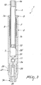
- a locking device for mechanical pieces particularly for pieces subjected to mechanical processing or similar, generally designated by the reference numeral 1, comprises at least one hollow body 2, also known as containment jacket, which forms a sliding seat 3, a movable stem 4, which is accommodated slidingly partially within the sliding seat 3, and radial expansion means 5, which are interposed between the hollow body 2 and the movable stem 4 and are adapted to mutually lock the two elements.
- the hollow body 2 is substantially cylindrical and the sliding seat 3 is blind, having a single opening 6 through which the movable stem 4 protrudes partially from the hollow body 2.
- the radial expansion means 5 comprise a tubular element 7, also known as expansion jacket, which is elastically deformable, is fitted slidingly on the movable stem 4 and is jointly accommodated with play within the sliding seat 3 so as to form, between the outside wall of the tubular element 7 and the inside wall of the sliding seat 3, at least one empty interspace 8, which is closed and can be connected functionally to a system 32 for dispensing a pressurized fluid 9, for example oil, in order to introduce the pressurized fluid 9 in the interspace 8 so as to deform elastically the tubular element 7 in a radial direction and block the translational motions of the movable stem 4 with respect to the hollow body 2 and vice versa, by friction between the movable stem 4 and the tubular element 7, as a consequence of the increase in pressure inside the interspace 8.
- a pressurized fluid for example oil
- tubular element 7 comprises a flanged end 7a, which acts as a closure plug for the sliding seat 3.
- the connector element 10 which substantially consists of a hydraulic valve, comprises a cylindrical body 1 1 , which can be screwed into a threaded hole 12 which is formed on the surface of the hollow body 2 and is connected to the interspace 8.
- a piston 14 is accommodated slidingly within the cylindrical body 11, forms the flow control element of the valve and can be locked therein by means of an elastic ring 13 and a threaded grub 15.
- the hollow body 2 and the movable stem 4 by being mutually lockable, thus form a strut of the type with a variable length, which can be interposed between a mechanical piece 16 to be processed and a fixed part 17, for example a perforated plate 18, of a machine with which the mechanical piece 16 is to be processed, as shown in Figure 4 .
- hollow body 2 and the movable stem 4 can be jointly associated, at their free ends 2a and 4a, by way of connection means 20, respectively with the mechanical piece 16 to be processed or the fixed part 17 of the machine with which the processing is to be performed.
- connection means 20 comprise two fixing heads 21 , one for each one of the free ends 2a and 4a, for the connection of the free ends 2a and 4a respectively to the mechanical piece 16 and to the fixed part 17 of the machine.
- Each fixing head 21 is associated with the respective free end 2a or 4a by means of a pivot 22, which is jointly connected in translational motion to the respective free end 2a or 4a and ends with a ring 23 which is accommodated in a fork-like element 24, which can be fixed to the mechanical piece 16 to be processed or to the fixed part 17 of the machine with which the processing is to be performed.
- At least one joint 25 is provided for the orientation of the hollow body 2 and of the movable stem 4 with respect to the mechanical piece 16 and with respect to the fixed part 17.
- each joint 25 has a locking screw 26, which is adapted to mutually couple the parts that form the joint 25.
- the adjustment means 27 comprise at least one threaded ring 28, which can be screwed onto a threaded shank 29 formed by one of the free ends 2a and 4a and more precisely, in the proposed embodiment, by the free end 2a, and is associated rotatably with a support 34 in which one of the pivots 22 is screwed by means of the threaded hole 35.
- connection means 20 related to the free end 2a i.e., the respective pivot 22, are associated directly with the threaded ring 28.
- means 29' for limiting the stroke of the movable stem 4 with respect to the hollow body 2 which comprise a flanged element 30, which is associated with the end of the movable stem 4 that is inserted in the hollow body 2.
- the flanged element 30 can engage by abutment alternately an end portion 7b of the tubular element 7 that is accommodated in the hollow body 2 or an abutment wall 31 that is formed in the hollow body 2 and more precisely by the bottom of the sliding seat 3, respectively, to define the maximum or minimum extraction position of the movable stem 4 with respect to the hollow body 2.
- the pressurized fluid 9 is pumped into the interspace 8, deforming radially the tubular element 8 so as to couple axially the hollow body 2 and the movable stem 4 to each other.
- the locking device 1 is tensioned further, so as to further stabilize the mechanical piece 16 with respect to the fixed part 17 of the machine, making the locking device 1 work both by traction and by compression.
- This stabilization can occur manually or by means of a hook wrench, so as to provide controlled preloadings.
- the locking device for mechanical pieces particularly for pieces subjected to mechanical processing or similar, according to the present invention, fully achieves the intended aim and object, since it allows to provide a system for gripping the piece to be processed that can be modulated extremely, such as to allow processing of mechanical pieces having different dimensions and shapes, reducing the number of fixture elements to be used to lock the mechanical piece to be processed and the machine.
- the simplicity of the locking device according to the present invention allows rapid use thereof with consequent reduction of transit time and machine downtime.
- Another advantage of the locking device according to the present invention is that it is possible to stabilize the mechanical piece to be processed during processing even in the presence of an irregular geometry that would require custom-made fixtures.
- a further advantage of the locking device according to the present invention is that it is possible to avoid flexing and vibration during processing steps due to the thrust of the tool on the mechanical piece being processed.
- Another advantage of the locking device according to the present invention is that it is possible to avoid locking tensions on the mechanical piece to be processed which might move such piece from its original position.
- a further advantage of the locking device according to the present invention is that it facilitates the operation for locking the piece to be processed.
- Another advantage of the locking device according to the present invention is that it is compact thanks to its elongated shape.
- a further advantage of the locking device according to the present invention is that it facilitates the operation for locking the piece to be processed.
Landscapes
- Engineering & Computer Science (AREA)
- Mechanical Engineering (AREA)
- General Engineering & Computer Science (AREA)
- Clamps And Clips (AREA)
- Mutual Connection Of Rods And Tubes (AREA)
- Jigs For Machine Tools (AREA)
- Snaps, Bayonet Connections, Set Pins, And Snap Rings (AREA)
Claims (11)
- Verriegelungsvorrichtung (1) für mechanische Teile, im Besonderen für Teile mit mechanischer Bearbeitung oder dergleichen, umfassend mindestens einen Hohlkörper (2), der einen Schiebesitz (3) bildet, einen partiell gleitend in dem genannten Schiebesitz (3) untergebrachten beweglichen Stößel (4), wobei der genannte bewegliche Schaft (4) partiell aus dem genannten Hohlkörper (2) vorsteht und der genannte Hohlkörper (2) und der genannte bewegliche Stößel (4) zusammenwirkend an ihren freien Enden (2a, 4a) mittels Verbindungselementen (20) jeweils mit einem zu bearbeitenden mechanischen Teil (16) oder einem festen Abschnitt (17) einer Maschine, mit der das genannte mechanische Teil (16) bearbeitet werden soll, verbunden werden können;
wobei die genannte Verriegelungsvorrichtung (1) dadurch gekennzeichnet ist, dass sie zwischen dem genannten Hohlkörper (2) und dem genannten beweglichen Stößel (4) eingesetzte radiale Ausdehnungselemente (5) umfasst, die geeignet sind, den genannten Hohlkörper (2) und den genannten beweglichen Stößel (4) gegeneinander zu verriegeln. - Verriegelungsvorrichtung (1) nach Anspruch 1, dadurch gekennzeichnet, dass die genannten radialen Ausdehnungselemente (5) ein elastisch verformbares Rohrelement (7) umfassen, das verschiebbar auf dem genannten beweglichen Stößel (4) angebracht und zusammenwirkend mit Spiel in dem genannten Schiebesitz (3) untergebracht ist, um zwischen der Außenwand des genannten Rohrelements (7) und der Innenwand des genannten Schiebesitzes (3) mindestens einen leeren Zwischenraum (8) zu bilden, der geschlossen ist und funktionell an ein System (32) zur Ausgabe eines unter Druck stehenden Betriebsmediums (9) angeschlossen werden kann, um das genannte unter Druck stehende Betriebsmedium (9) in den genannten mindestens einen Zwischenraum (8) einzuleiten, um das genannte Rohrelement (7) elastisch zu verformen und die Versetzungsbewegungen des genannten beweglichen Stößels (4) im Verhältnis zu dem genannten Hohlkörper (2) und umgekehrt als Folge des Druckanstiegs in dem genannten mindestens einen Zwischenraum (8) zu verriegeln.
- Verriegelungsvorrichtung (1) nach einem oder mehreren der vorangegangenen Ansprüche, dadurch gekennzeichnet, dass der genannte Hohlkörper (2) im Wesentlichen zylindrisch ist.
- Verriegelungsvorrichtung (1) nach Anspruch 2, dadurch gekennzeichnet, dass sie mindestens ein Verbindungselement (10) umfasst, das zusammenwirkend mit dem genannten Hohlkörper (2) und mit dem genannten mindestens einem Zwischenraum (8) verbunden ist und mit dem genannten Ausgabesystem (32) für den Durchgang des genannten unter Druck stehenden Betriebsmediums (9) in den genannten mindestens einen Zwischenraum (8) verbunden werden kann.
- Verriegelungsvorrichtung (1) nach einem oder mehreren der vorangegangenen Ansprüche, dadurch gekennzeichnet, dass die genannten Verbindungselemente (20) zwei Befestigungsköpfe (22), einen für jedes der genannten freien Enden (2a, 4a), für die Verbindung der genannten freien Enden (2a, 4a) jeweils mit dem genannten mechanischen Teil (16) und dem genannten festen Abschnitt (17), umfassen, wobei die genannten Befestigungsköpfe (22) mindestens ein Gelenk (25) für die Ausrichtung des genannten Hohlkörpers (2) und des genannten beweglichen Stößels (4) im Verhältnis zu dem genannten mechanischen Teil (16) und im Verhältnis zu dem genannten festen Abschnitt (17) umfassen.
- Verriegelungsvorrichtung (1) nach einem oder mehreren der vorangegangenen Ansprüche, dadurch gekennzeichnet, dass sie Elemente (27) zur Anpassung der Spannung des genannten Hohlkörpers (2) und des genannten beweglichen Stößels (4) umfasst, die gegenseitig mittels der genannten radialen Ausdehnungselemente (5) verriegelt und jeweils mit dem genannten mechanischen Teil (16) und dem genannten festen Abschnitt (17) mittels der genannten Verbindungselemente (20) verbunden sind.
- Verriegelungsvorrichtung (1) nach Anspruch 6, dadurch gekennzeichnet, dass die genannten Anpassungselemente (27) mindestens einen Gewindering (28) umfassen, der auf einen von einem der freien Enden (2a) gebildeten Gewindeschaft (29) geschraubt werden kann, wobei die zu dem genannten freien Ende (2a) gehörenden genannten Verbindungselemente (20) mit dem genannten Gewindering (28) verbunden sind.
- Verriegelungsvorrichtung (1) nach einem oder mehreren der vorangegangenen Ansprüche, dadurch gekennzeichnet, dass der genannte bewegliche Stößel (4) je nach Anforderungen aus einer Vielzahl von modularen Abschnitten (19) besteht.
- Verriegelungsvorrichtung (1) nach einem oder mehreren der vorangegangenen Ansprüche, dadurch gekennzeichnet, dass sie Elemente (29') zur Begrenzung des Hubs des genannten beweglichen Stößels (4) in Bezug auf den Hohlkörper (2) umfasst.
- Verriegelungsvorrichtung (1) nach Anspruch 9, dadurch gekennzeichnet, dass die genannten hubbegrenzenden Elemente (29') ein geflanschtes Element (30) umfassen, das mit dem in den genannten Hohlkörper (2) eingesetzten Ende des genannten beweglichen Stößels (4) verbunden ist, wobei das genannte geflanschte Element (30) durch Anschlagen sich abwechselnd jeweils mit einem Endabschnitt (7b) des in dem genannten Hohlkörper (2) untergebrachten genannten Rohrelements (7) oder mit einer in dem genannten Hohlkörper (2) ausgebildeten Anschlagswand (31) im Eingriff befinden kann, um die maximale oder minimale Austrittsposition des genannten beweglichen Stößels (4) im Verhältnis zu dem genannten Hohlkörper (2) zu definieren.
- Verriegelungsvorrichtung (1) nach Anspruch 10, dadurch gekennzeichnet, dass der Schiebesitz (3) blind ist und die genannte Anschlagswand (31) von der Unterseite des genannten Schiebesitzes (3) gebildet wird.
Priority Applications (1)
| Application Number | Priority Date | Filing Date | Title |
|---|---|---|---|
| PT10763874T PT2608933T (pt) | 2010-08-24 | 2010-08-24 | Dispositivo de travamento para peças mecânicas, particularmente para peças submetidas a processamento mecânico ou similar |
Applications Claiming Priority (1)
| Application Number | Priority Date | Filing Date | Title |
|---|---|---|---|
| PCT/IT2010/000373 WO2012025945A1 (en) | 2010-08-24 | 2010-08-24 | Locking device for mechanical pieces, particularly for piece subjected to mechanical processing or similar |
Publications (2)
| Publication Number | Publication Date |
|---|---|
| EP2608933A1 EP2608933A1 (de) | 2013-07-03 |
| EP2608933B1 true EP2608933B1 (de) | 2018-11-21 |
Family
ID=43795147
Family Applications (1)
| Application Number | Title | Priority Date | Filing Date |
|---|---|---|---|
| EP10763874.4A Not-in-force EP2608933B1 (de) | 2010-08-24 | 2010-08-24 | Verriegelungsvorrichtung für mechanische teile, im besonderen für teile mit mechanischer bearbeitung oder dergleichen |
Country Status (10)
| Country | Link |
|---|---|
| US (1) | US9562551B2 (de) |
| EP (1) | EP2608933B1 (de) |
| JP (1) | JP5669944B2 (de) |
| KR (1) | KR20130101509A (de) |
| CN (1) | CN103068527B (de) |
| BR (1) | BR112013003490A2 (de) |
| CA (1) | CA2808143C (de) |
| ES (1) | ES2711548T3 (de) |
| PT (1) | PT2608933T (de) |
| WO (1) | WO2012025945A1 (de) |
Families Citing this family (4)
| Publication number | Priority date | Publication date | Assignee | Title |
|---|---|---|---|---|
| CN107443274B (zh) * | 2017-09-07 | 2019-07-05 | 安徽涌诚机械有限公司 | 大型工件小批量多用途夹具 |
| DE112019007360A5 (de) * | 2019-07-01 | 2022-03-17 | Josef Weischer GmbH & Co. KG | Vorrichtung zur lösbaren Fixierung eines zu vermessenden und/oder zu bearbeitenden Werkstücks und Verfahren zur Lagerung eines Werkstücks mit derartigen Vorrichtungen |
| DE102019130877A1 (de) * | 2019-11-15 | 2021-05-20 | Andreas Maier Gmbh & Co. Kg | Modularer Abstützbock |
| DE102020122709A1 (de) | 2020-08-31 | 2022-03-03 | Gressel Ag | Spannvorrichtung |
Family Cites Families (19)
| Publication number | Priority date | Publication date | Assignee | Title |
|---|---|---|---|---|
| US500908A (en) * | 1893-07-04 | August kampf | ||
| US2453855A (en) * | 1947-11-21 | 1948-11-16 | Adel Prec Products Corp | Hydraulic lock |
| US3528532A (en) * | 1968-08-21 | 1970-09-15 | Eugene D Moskow | Hydraulic locking device |
| US4111068A (en) * | 1977-03-07 | 1978-09-05 | Nasa | Locking redundant link |
| US4453745A (en) * | 1981-08-17 | 1984-06-12 | Nelson Norman A | Lockdown mechanism for wellhead connector |
| JPS59171040U (ja) * | 1983-04-27 | 1984-11-15 | 新日本工機株式会社 | クロスレ−ルクランプ装置 |
| DE8903660U1 (de) * | 1989-03-20 | 1989-05-18 | Siemens AG, 1000 Berlin und 8000 München | Stützvorrichtung für Werkstücke |
| US5305992A (en) | 1993-04-19 | 1994-04-26 | The Budd Company | Measuring fixture with gauge ball |
| US6055762A (en) * | 1998-05-01 | 2000-05-02 | Philpot; Terry | Combined boat hook and bilge pump |
| JP2001062659A (ja) * | 1999-08-27 | 2001-03-13 | Nissan Motor Co Ltd | 位置決め装置および位置決め方法 |
| JP2004223702A (ja) * | 2002-11-29 | 2004-08-12 | Kosmek Ltd | 位置決め装置 |
| US7246779B2 (en) * | 2002-12-18 | 2007-07-24 | Suspa Incorporated | Telescopic legs and tables |
| CN2679971Y (zh) * | 2004-01-09 | 2005-02-16 | 广达电脑股份有限公司 | 锁定工具 |
| JP3970887B2 (ja) * | 2005-04-15 | 2007-09-05 | 本田技研工業株式会社 | クランプ装置 |
| US8215224B1 (en) * | 2006-06-22 | 2012-07-10 | The United States Of America As Represented By The Secretary Of The Army | Variable recoil brake for munition |
| US7735810B2 (en) * | 2006-08-24 | 2010-06-15 | William Pope | Vehicle door strut support |
| CN201261172Y (zh) * | 2008-09-09 | 2009-06-24 | 东莞市吉川机械设备有限公司 | 一种杆状工件夹具 |
| US8556209B2 (en) * | 2008-10-22 | 2013-10-15 | Goodrich Corporation | Electric-powered transfer cylinder for landing gear system |
| US8070095B2 (en) * | 2008-10-22 | 2011-12-06 | Goodrich Corporation | Shrinking shock strut system for retractable landing gear |
-
2010
- 2010-08-24 CN CN201080068739.6A patent/CN103068527B/zh not_active Expired - Fee Related
- 2010-08-24 EP EP10763874.4A patent/EP2608933B1/de not_active Not-in-force
- 2010-08-24 WO PCT/IT2010/000373 patent/WO2012025945A1/en not_active Ceased
- 2010-08-24 JP JP2013525426A patent/JP5669944B2/ja not_active Expired - Fee Related
- 2010-08-24 ES ES10763874T patent/ES2711548T3/es active Active
- 2010-08-24 US US13/818,728 patent/US9562551B2/en active Active
- 2010-08-24 KR KR1020137006452A patent/KR20130101509A/ko not_active Ceased
- 2010-08-24 CA CA2808143A patent/CA2808143C/en not_active Expired - Fee Related
- 2010-08-24 BR BR112013003490A patent/BR112013003490A2/pt not_active IP Right Cessation
- 2010-08-24 PT PT10763874T patent/PT2608933T/pt unknown
Non-Patent Citations (1)
| Title |
|---|
| None * |
Also Published As
| Publication number | Publication date |
|---|---|
| US9562551B2 (en) | 2017-02-07 |
| PT2608933T (pt) | 2019-02-25 |
| CA2808143A1 (en) | 2012-03-01 |
| KR20130101509A (ko) | 2013-09-13 |
| WO2012025945A1 (en) | 2012-03-01 |
| ES2711548T3 (es) | 2019-05-06 |
| EP2608933A1 (de) | 2013-07-03 |
| CA2808143C (en) | 2017-09-26 |
| CN103068527A (zh) | 2013-04-24 |
| JP2013539416A (ja) | 2013-10-24 |
| JP5669944B2 (ja) | 2015-02-18 |
| US20130156491A1 (en) | 2013-06-20 |
| CN103068527B (zh) | 2015-09-30 |
| BR112013003490A2 (pt) | 2019-09-24 |
Similar Documents
| Publication | Publication Date | Title |
|---|---|---|
| US9321109B2 (en) | Power operated chuck | |
| US10005175B2 (en) | Steering shock compressor systems and methods | |
| US9562551B2 (en) | Locking device for mechanical pieces, particularly for piece subjected to mechanical processing or similar | |
| EP3078449B1 (de) | Spannvorrichtung | |
| EP2849917B1 (de) | Verstellbare verbindungsklemme | |
| RU2013126931A (ru) | Выталкиватель штифта в подъемном кране и его применение | |
| NO324670B1 (no) | Hurtigkoplingsmutter | |
| EP3791096B1 (de) | Durchflussregelventilanordnung und zugehöriges einstellwerkzeugset | |
| US20170097099A1 (en) | System and method for valve assembly | |
| US6609706B2 (en) | Work fixing jig for machine tools | |
| KR20150089410A (ko) | 부싱 교환 작업용 가변형 어댑터 | |
| EP3214335B1 (de) | Autonome hydraulische expansions- und kontraktionsvorrichtung | |
| KR101639948B1 (ko) | 핀제거 장치 | |
| HK1185836A (en) | Locking device for mechanical pieces, particularly for piece subjected to mechanical processing or similar | |
| HK1185836B (en) | Locking device for mechanical pieces, particularly for piece subjected to mechanical processing or similar | |
| US9943950B2 (en) | Threaded pin remover | |
| CN102950495B (zh) | 工装辅助支撑机构 | |
| US20150251239A1 (en) | Blind rivet setting device | |
| EP4363158B1 (de) | Vorrichtung zum spannen von werkstücken auf werkzeugmaschinen | |
| CN118757479A (zh) | 一种多级液压缸及其安装方法 | |
| JP2012516421A (ja) | 調節可能なピストンアクチュエータ | |
| CN212351789U (zh) | 一种预拧螺栓的套筒 | |
| KR20190006700A (ko) | 치공구용 클램핑 장치 | |
| KR101624579B1 (ko) | 프레스기용 안전장치 | |
| JPH01232005A (ja) | 型締装置 |
Legal Events
| Date | Code | Title | Description |
|---|---|---|---|
| PUAI | Public reference made under article 153(3) epc to a published international application that has entered the european phase |
Free format text: ORIGINAL CODE: 0009012 |
|
| 17P | Request for examination filed |
Effective date: 20130211 |
|
| AK | Designated contracting states |
Kind code of ref document: A1 Designated state(s): AL AT BE BG CH CY CZ DE DK EE ES FI FR GB GR HR HU IE IS IT LI LT LU LV MC MK MT NL NO PL PT RO SE SI SK SM TR |
|
| DAX | Request for extension of the european patent (deleted) | ||
| REG | Reference to a national code |
Ref country code: HK Ref legal event code: DE Ref document number: 1185836 Country of ref document: HK |
|
| 17Q | First examination report despatched |
Effective date: 20150827 |
|
| GRAP | Despatch of communication of intention to grant a patent |
Free format text: ORIGINAL CODE: EPIDOSNIGR1 |
|
| STAA | Information on the status of an ep patent application or granted ep patent |
Free format text: STATUS: GRANT OF PATENT IS INTENDED |
|
| RIC1 | Information provided on ipc code assigned before grant |
Ipc: B23Q 3/10 20060101ALI20180514BHEP Ipc: B25B 11/00 20060101AFI20180514BHEP Ipc: F16B 7/14 20060101ALI20180514BHEP |
|
| INTG | Intention to grant announced |
Effective date: 20180607 |
|
| GRAS | Grant fee paid |
Free format text: ORIGINAL CODE: EPIDOSNIGR3 |
|
| GRAA | (expected) grant |
Free format text: ORIGINAL CODE: 0009210 |
|
| STAA | Information on the status of an ep patent application or granted ep patent |
Free format text: STATUS: THE PATENT HAS BEEN GRANTED |
|
| AK | Designated contracting states |
Kind code of ref document: B1 Designated state(s): AL AT BE BG CH CY CZ DE DK EE ES FI FR GB GR HR HU IE IS IT LI LT LU LV MC MK MT NL NO PL PT RO SE SI SK SM TR |
|
| REG | Reference to a national code |
Ref country code: CH Ref legal event code: EP |
|
| REG | Reference to a national code |
Ref country code: IE Ref legal event code: FG4D |
|
| REG | Reference to a national code |
Ref country code: DE Ref legal event code: R096 Ref document number: 602010055288 Country of ref document: DE |
|
| REG | Reference to a national code |
Ref country code: AT Ref legal event code: REF Ref document number: 1066998 Country of ref document: AT Kind code of ref document: T Effective date: 20181215 |
|
| REG | Reference to a national code |
Ref country code: PT Ref legal event code: SC4A Ref document number: 2608933 Country of ref document: PT Date of ref document: 20190225 Kind code of ref document: T Free format text: AVAILABILITY OF NATIONAL TRANSLATION Effective date: 20190214 |
|
| REG | Reference to a national code |
Ref country code: CH Ref legal event code: NV Representative=s name: KIRKER AND CIE S.A., CH |
|
| REG | Reference to a national code |
Ref country code: NL Ref legal event code: MP Effective date: 20181121 |
|
| PG25 | Lapsed in a contracting state [announced via postgrant information from national office to epo] |
Ref country code: IS Free format text: LAPSE BECAUSE OF FAILURE TO SUBMIT A TRANSLATION OF THE DESCRIPTION OR TO PAY THE FEE WITHIN THE PRESCRIBED TIME-LIMIT Effective date: 20190321 Ref country code: LT Free format text: LAPSE BECAUSE OF FAILURE TO SUBMIT A TRANSLATION OF THE DESCRIPTION OR TO PAY THE FEE WITHIN THE PRESCRIBED TIME-LIMIT Effective date: 20181121 Ref country code: HR Free format text: LAPSE BECAUSE OF FAILURE TO SUBMIT A TRANSLATION OF THE DESCRIPTION OR TO PAY THE FEE WITHIN THE PRESCRIBED TIME-LIMIT Effective date: 20181121 Ref country code: BG Free format text: LAPSE BECAUSE OF FAILURE TO SUBMIT A TRANSLATION OF THE DESCRIPTION OR TO PAY THE FEE WITHIN THE PRESCRIBED TIME-LIMIT Effective date: 20190221 Ref country code: LV Free format text: LAPSE BECAUSE OF FAILURE TO SUBMIT A TRANSLATION OF THE DESCRIPTION OR TO PAY THE FEE WITHIN THE PRESCRIBED TIME-LIMIT Effective date: 20181121 Ref country code: NO Free format text: LAPSE BECAUSE OF FAILURE TO SUBMIT A TRANSLATION OF THE DESCRIPTION OR TO PAY THE FEE WITHIN THE PRESCRIBED TIME-LIMIT Effective date: 20190221 Ref country code: FI Free format text: LAPSE BECAUSE OF FAILURE TO SUBMIT A TRANSLATION OF THE DESCRIPTION OR TO PAY THE FEE WITHIN THE PRESCRIBED TIME-LIMIT Effective date: 20181121 |
|
| REG | Reference to a national code |
Ref country code: ES Ref legal event code: FG2A Ref document number: 2711548 Country of ref document: ES Kind code of ref document: T3 Effective date: 20190506 |
|
| PG25 | Lapsed in a contracting state [announced via postgrant information from national office to epo] |
Ref country code: AL Free format text: LAPSE BECAUSE OF FAILURE TO SUBMIT A TRANSLATION OF THE DESCRIPTION OR TO PAY THE FEE WITHIN THE PRESCRIBED TIME-LIMIT Effective date: 20181121 Ref country code: SE Free format text: LAPSE BECAUSE OF FAILURE TO SUBMIT A TRANSLATION OF THE DESCRIPTION OR TO PAY THE FEE WITHIN THE PRESCRIBED TIME-LIMIT Effective date: 20181121 Ref country code: GR Free format text: LAPSE BECAUSE OF FAILURE TO SUBMIT A TRANSLATION OF THE DESCRIPTION OR TO PAY THE FEE WITHIN THE PRESCRIBED TIME-LIMIT Effective date: 20190222 Ref country code: NL Free format text: LAPSE BECAUSE OF FAILURE TO SUBMIT A TRANSLATION OF THE DESCRIPTION OR TO PAY THE FEE WITHIN THE PRESCRIBED TIME-LIMIT Effective date: 20181121 |
|
| PG25 | Lapsed in a contracting state [announced via postgrant information from national office to epo] |
Ref country code: CZ Free format text: LAPSE BECAUSE OF FAILURE TO SUBMIT A TRANSLATION OF THE DESCRIPTION OR TO PAY THE FEE WITHIN THE PRESCRIBED TIME-LIMIT Effective date: 20181121 Ref country code: DK Free format text: LAPSE BECAUSE OF FAILURE TO SUBMIT A TRANSLATION OF THE DESCRIPTION OR TO PAY THE FEE WITHIN THE PRESCRIBED TIME-LIMIT Effective date: 20181121 Ref country code: PL Free format text: LAPSE BECAUSE OF FAILURE TO SUBMIT A TRANSLATION OF THE DESCRIPTION OR TO PAY THE FEE WITHIN THE PRESCRIBED TIME-LIMIT Effective date: 20181121 |
|
| REG | Reference to a national code |
Ref country code: DE Ref legal event code: R097 Ref document number: 602010055288 Country of ref document: DE |
|
| PG25 | Lapsed in a contracting state [announced via postgrant information from national office to epo] |
Ref country code: SK Free format text: LAPSE BECAUSE OF FAILURE TO SUBMIT A TRANSLATION OF THE DESCRIPTION OR TO PAY THE FEE WITHIN THE PRESCRIBED TIME-LIMIT Effective date: 20181121 Ref country code: RO Free format text: LAPSE BECAUSE OF FAILURE TO SUBMIT A TRANSLATION OF THE DESCRIPTION OR TO PAY THE FEE WITHIN THE PRESCRIBED TIME-LIMIT Effective date: 20181121 Ref country code: EE Free format text: LAPSE BECAUSE OF FAILURE TO SUBMIT A TRANSLATION OF THE DESCRIPTION OR TO PAY THE FEE WITHIN THE PRESCRIBED TIME-LIMIT Effective date: 20181121 Ref country code: SM Free format text: LAPSE BECAUSE OF FAILURE TO SUBMIT A TRANSLATION OF THE DESCRIPTION OR TO PAY THE FEE WITHIN THE PRESCRIBED TIME-LIMIT Effective date: 20181121 |
|
| PLBE | No opposition filed within time limit |
Free format text: ORIGINAL CODE: 0009261 |
|
| STAA | Information on the status of an ep patent application or granted ep patent |
Free format text: STATUS: NO OPPOSITION FILED WITHIN TIME LIMIT |
|
| 26N | No opposition filed |
Effective date: 20190822 |
|
| PG25 | Lapsed in a contracting state [announced via postgrant information from national office to epo] |
Ref country code: SI Free format text: LAPSE BECAUSE OF FAILURE TO SUBMIT A TRANSLATION OF THE DESCRIPTION OR TO PAY THE FEE WITHIN THE PRESCRIBED TIME-LIMIT Effective date: 20181121 |
|
| PG25 | Lapsed in a contracting state [announced via postgrant information from national office to epo] |
Ref country code: TR Free format text: LAPSE BECAUSE OF FAILURE TO SUBMIT A TRANSLATION OF THE DESCRIPTION OR TO PAY THE FEE WITHIN THE PRESCRIBED TIME-LIMIT Effective date: 20181121 |
|
| GBPC | Gb: european patent ceased through non-payment of renewal fee |
Effective date: 20190824 |
|
| PG25 | Lapsed in a contracting state [announced via postgrant information from national office to epo] |
Ref country code: MC Free format text: LAPSE BECAUSE OF FAILURE TO SUBMIT A TRANSLATION OF THE DESCRIPTION OR TO PAY THE FEE WITHIN THE PRESCRIBED TIME-LIMIT Effective date: 20181121 Ref country code: LU Free format text: LAPSE BECAUSE OF NON-PAYMENT OF DUE FEES Effective date: 20190824 |
|
| REG | Reference to a national code |
Ref country code: BE Ref legal event code: MM Effective date: 20190831 |
|
| PG25 | Lapsed in a contracting state [announced via postgrant information from national office to epo] |
Ref country code: IE Free format text: LAPSE BECAUSE OF NON-PAYMENT OF DUE FEES Effective date: 20190824 |
|
| REG | Reference to a national code |
Ref country code: AT Ref legal event code: UEP Ref document number: 1066998 Country of ref document: AT Kind code of ref document: T Effective date: 20181121 |
|
| PG25 | Lapsed in a contracting state [announced via postgrant information from national office to epo] |
Ref country code: BE Free format text: LAPSE BECAUSE OF NON-PAYMENT OF DUE FEES Effective date: 20190831 Ref country code: GB Free format text: LAPSE BECAUSE OF NON-PAYMENT OF DUE FEES Effective date: 20190824 |
|
| PGFP | Annual fee paid to national office [announced via postgrant information from national office to epo] |
Ref country code: DE Payment date: 20200819 Year of fee payment: 11 Ref country code: PT Payment date: 20200820 Year of fee payment: 11 Ref country code: FR Payment date: 20200821 Year of fee payment: 11 |
|
| PGFP | Annual fee paid to national office [announced via postgrant information from national office to epo] |
Ref country code: AT Payment date: 20200820 Year of fee payment: 11 Ref country code: IT Payment date: 20200731 Year of fee payment: 11 Ref country code: CH Payment date: 20200819 Year of fee payment: 11 |
|
| PGFP | Annual fee paid to national office [announced via postgrant information from national office to epo] |
Ref country code: ES Payment date: 20201023 Year of fee payment: 11 |
|
| PG25 | Lapsed in a contracting state [announced via postgrant information from national office to epo] |
Ref country code: CY Free format text: LAPSE BECAUSE OF FAILURE TO SUBMIT A TRANSLATION OF THE DESCRIPTION OR TO PAY THE FEE WITHIN THE PRESCRIBED TIME-LIMIT Effective date: 20181121 |
|
| PG25 | Lapsed in a contracting state [announced via postgrant information from national office to epo] |
Ref country code: HU Free format text: LAPSE BECAUSE OF FAILURE TO SUBMIT A TRANSLATION OF THE DESCRIPTION OR TO PAY THE FEE WITHIN THE PRESCRIBED TIME-LIMIT; INVALID AB INITIO Effective date: 20100824 Ref country code: MT Free format text: LAPSE BECAUSE OF FAILURE TO SUBMIT A TRANSLATION OF THE DESCRIPTION OR TO PAY THE FEE WITHIN THE PRESCRIBED TIME-LIMIT Effective date: 20181121 |
|
| REG | Reference to a national code |
Ref country code: DE Ref legal event code: R119 Ref document number: 602010055288 Country of ref document: DE |
|
| REG | Reference to a national code |
Ref country code: CH Ref legal event code: PL |
|
| REG | Reference to a national code |
Ref country code: AT Ref legal event code: MM01 Ref document number: 1066998 Country of ref document: AT Kind code of ref document: T Effective date: 20210824 |
|
| PG25 | Lapsed in a contracting state [announced via postgrant information from national office to epo] |
Ref country code: LI Free format text: LAPSE BECAUSE OF NON-PAYMENT OF DUE FEES Effective date: 20210831 Ref country code: CH Free format text: LAPSE BECAUSE OF NON-PAYMENT OF DUE FEES Effective date: 20210831 Ref country code: AT Free format text: LAPSE BECAUSE OF NON-PAYMENT OF DUE FEES Effective date: 20210824 |
|
| PG25 | Lapsed in a contracting state [announced via postgrant information from national office to epo] |
Ref country code: PT Free format text: LAPSE BECAUSE OF NON-PAYMENT OF DUE FEES Effective date: 20220224 |
|
| PG25 | Lapsed in a contracting state [announced via postgrant information from national office to epo] |
Ref country code: MK Free format text: LAPSE BECAUSE OF FAILURE TO SUBMIT A TRANSLATION OF THE DESCRIPTION OR TO PAY THE FEE WITHIN THE PRESCRIBED TIME-LIMIT Effective date: 20181121 |
|
| PG25 | Lapsed in a contracting state [announced via postgrant information from national office to epo] |
Ref country code: IT Free format text: LAPSE BECAUSE OF NON-PAYMENT OF DUE FEES Effective date: 20210824 Ref country code: FR Free format text: LAPSE BECAUSE OF NON-PAYMENT OF DUE FEES Effective date: 20210831 Ref country code: DE Free format text: LAPSE BECAUSE OF NON-PAYMENT OF DUE FEES Effective date: 20220301 |
|
| REG | Reference to a national code |
Ref country code: ES Ref legal event code: FD2A Effective date: 20221027 |
|
| PG25 | Lapsed in a contracting state [announced via postgrant information from national office to epo] |
Ref country code: ES Free format text: LAPSE BECAUSE OF NON-PAYMENT OF DUE FEES Effective date: 20210825 |