EP2607842A2 - Dispositif de mesure multifonction - Google Patents
Dispositif de mesure multifonction Download PDFInfo
- Publication number
- EP2607842A2 EP2607842A2 EP12160417.7A EP12160417A EP2607842A2 EP 2607842 A2 EP2607842 A2 EP 2607842A2 EP 12160417 A EP12160417 A EP 12160417A EP 2607842 A2 EP2607842 A2 EP 2607842A2
- Authority
- EP
- European Patent Office
- Prior art keywords
- housing
- mounting seat
- measuring device
- lens
- viewing hole
- Prior art date
- Legal status (The legal status is an assumption and is not a legal conclusion. Google has not performed a legal analysis and makes no representation as to the accuracy of the status listed.)
- Withdrawn
Links
Images


Classifications
-
- G—PHYSICS
- G01—MEASURING; TESTING
- G01C—MEASURING DISTANCES, LEVELS OR BEARINGS; SURVEYING; NAVIGATION; GYROSCOPIC INSTRUMENTS; PHOTOGRAMMETRY OR VIDEOGRAMMETRY
- G01C23/00—Combined instruments indicating more than one navigational value, e.g. for aircraft; Combined measuring devices for measuring two or more variables of movement, e.g. distance, speed or acceleration
-
- G—PHYSICS
- G01—MEASURING; TESTING
- G01C—MEASURING DISTANCES, LEVELS OR BEARINGS; SURVEYING; NAVIGATION; GYROSCOPIC INSTRUMENTS; PHOTOGRAMMETRY OR VIDEOGRAMMETRY
- G01C17/00—Compasses; Devices for ascertaining true or magnetic north for navigation or surveying purposes
-
- G—PHYSICS
- G01—MEASURING; TESTING
- G01C—MEASURING DISTANCES, LEVELS OR BEARINGS; SURVEYING; NAVIGATION; GYROSCOPIC INSTRUMENTS; PHOTOGRAMMETRY OR VIDEOGRAMMETRY
- G01C9/00—Measuring inclination, e.g. by clinometers, by levels
- G01C9/18—Measuring inclination, e.g. by clinometers, by levels by using liquids
- G01C9/24—Measuring inclination, e.g. by clinometers, by levels by using liquids in closed containers partially filled with liquid so as to leave a gas bubble
- G01C9/26—Details
- G01C9/28—Mountings
Definitions
- the invention relates to a measuring instrument, and more particularly to a multifunction measuring device.
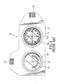
- a conventional measuring instrument 10 is shown to include: a housing 11; an inclinometer 12 and an orientation compass 13 mounted to a mounting surface of the housing 11; a first magnification-adjusting member 14 mounted to the housing 11, and operable to adjust an adequate focal distance for a user's eye so as to enable a built-in first magnifying lens (not shown) to adequately magnify scales on a scale ring 122 of the inclinometer 12 such that inclination angle information of the user's location can be clearly read from the scale ring 122 by the user; and a second magnification-adjusting member 15 mounted to the housing 11, and operable to adjust an adequate focal distance for a user's eye so as to enable a built-in second magnifying lens (not shown) to adequately magnify scales on a scale ring 132 of the orientation compass 13 such that orientation information of the user's location can be clearly read from the scale ring 132 by the user.
- the inclination angle information of the user's location can also be
- the conventional measuring instrument 10 since the inclinometer 12 and the orientation compass 13 are mounted to the same mounting surface of the housing 11, the conventional measuring instrument 10 has a relatively large size in length, and is inconvenient to carry.
- an object of the present invention is to provide a multifunction measuring device that can overcome the aforesaid drawbacks of the prior art.
- a multifunction measuring device of the present invention comprises:
- a multifunction measuring device according to the present invention is shown to include a housing 2, a mounting seat 4, an orientation measuring unit, an inclination angle measuring unit, a mirror 7, a thermometer 8, and a hanging rope 9.
- the housing 2 has opposite front and rear sides 23, 24, opposite lateral ends 25, 26, and opposite top and bottom ends 27, 28.
- the front side 23 is formed with a front opening 231.
- the rear side 24 is formed with a rear opening 241 aligned coaxially with the front opening 231 in the front side 23.
- the lateral end 25 is formed with a first viewing hole 251, and the top end 27 is formed with a second viewing hole 271, as best shown in Figure 6 .
- the housing 2 includes complementary front and rear housing parts 21, 22 connected to each other using a plurality of screw fasteners 100.
- the front housing part 21 is formed with the front opening 231.
- the rear housing 22 is formed with the rear opening 241.
- the front housing 21 cooperates with the rear housing 22 to define the first and second viewing holes 251, 271, and an insertion groove 29 (see Figure 6 ) therebetween.
- the insertion groove 29 extends downward from the top end 27 of the housing 2, and is disposed adjacent to the lateral end 26 of the housing 2.
- the insertion groove 29 is defined by a U-shaped groove-defining wall 291.
- the U-shaped groove-defining wall 291 includes opposite front and rear wall portions 291, 292, wherein the front wall portion 291 is a part of the front housing 21, and the rear wall portion 292 is a part of the rear housing 22.
- Each of the front and rear wall portions 291, 292 is formed with a plurality of positioning holes 2911, 2921.
- a transparent dust-proof piece 20 is mounted in the housing 2 for covering the second viewing hole 271 in the top end 27 of the housing 2.
- the mounting seat 4 is mounted fixedly in the housing 2, and is disposed coaxially with the front and rear openings 231, 241 in the housing 2.
- the mounting seat 4 includes a barrel body 42 connected to the rear housing part 22 using a plurality of screw fasteners 101 (see Figure 2 ), and a partition plate 41 mounted in the barrel body 42 and cooperating with the barrel body 42 to define a front receiving space 43 and a rear receiving space 44.
- the barrel body 42 has opposite front and rear end 421, 422.
- the front end 421 of the barrel body 42 is formed with a front notch 4211 that is in spatial communication with the front receiving space 43 and that is aligned with the first viewing hole 251 in the housing 2.
- the rear end 422 of the barrel body 42 is formed with a rear notch 4221 that is in spatial communication with the rear receiving space 44 and that is aligned with the second viewing hole 271 in the housing 2.
- the orientation measuring unit includes an orientation compass 51, a connecting seat 52, and a first magnification member.
- the orientation compass 51 is mounted in the mounting seat 4, and is received in the front receiving space 43 in the mounting seat 4.
- the orientation compass 51 has a compass scale 511 exposed through the front opening 231 in the housing 2, and a first scale ring 512 visible through the first viewing hole 251 and the front notch 4211 in the barrel body 42 of the mounting seat 4.
- the connecting seat 52 is mounted fixedly in the housing 2, and is disposed adjacent to the mounting seat 4 .
- the connecting seat 52 is formed with a through hole 521 that is aligned with the front notch 4211 in the barrel body 42 of the mounting seat 4 and the first viewing hole 251 in the housing 2.
- the through hole 521 is a screw hole.
- the first magnification member includes a tubular body 53, a first magnifying lens 54, a washer 55, an anchoring ring 4, and a protection cover 57.
- the tubular body 53 has a connecting end portion 531 with an annular outer thread surface extending into the through hole 521 in the connecting seat 52 and connected movably to the connecting seat 52, and an enlarged operating end portion 532 opposite to the connecting end portion 531 and extending outward of the housing 2 through the first viewing hole 251 (see Figure 6 ).
- the first magnifying lens 54 is mounted in the tubular body 53, and is received in the operating end portion 532 of the tubular body 53.
- the washer 55 is sleeved on the connecting end portion 531 of the tubular body 53.
- the anchoring ring 56 is disposed fittingly in the operating end portion 532 of the tubular body 53 for anchoring the first magnifying lens 54 in the tubular body 53.
- the protection cover 57 has a pivot end 571 connected pivotally to the housing 1 using a pivot rod 570 fixed in the housing 1, and a cover end 572 opposite to the pivot end 571.
- the cover end 572 of the protection cover 57 is in the form of a plug.
- the protection cover 57 is operable so that the cover end 572 plugged into and connected to the operating end portion 532 of the tubular body 53 so as to cover the first magnifying lens 54 in the tubular body 53 (see Figure 3 ).
- the cover end 572 of the protection cover 57 is moved away from the operating end portion 532 of the tubular body 53. Thereafter, the operating end portion 532 is rotated to adjust a distance between the first magnifying lens 54 and the first scale ring 512, i.e., an adequate focal distance for a user's eye, so as to enable the first magnifying lens 54 to adequately magnify scales on the first scale ring 512 of the orientation compass 51 such that orientation information of the user's location can be clearly read from the first scale ring 512 of the orientation compass 51 by the user.
- a distance between the first magnifying lens 54 and the first scale ring 512 i.e., an adequate focal distance for a user's eye
- the inclination angle measuring unlit includes an inclinometer 61, and a second magnification member.
- the inclinometer 61 is mounted in the mounting seat 4, and is received in the rear receiving space 44 in the mounting seat 4.
- the inclinometer 61 has an inclinometer scale 611 exposed through the rear opening 241 in the housing 2, and a second scale ring 612 visible through the second viewing hole 271 and the rear notch 4221 in the barrel body 42 of the mounting seat 4.
- the second magnification member includes a lens-mounting seat 62, a second magnifying lens 63, and a protection cover 64.
- the lens-mounting seat 62 is mounted on the housing 2, and is movable up and down relative to the housing 2.
- the lens-mounting seat 62 includes a vertical insertion block 621 insertedmovably into the insertion groove 29 in the housing 2, and a horizontal extension plate 622 connected to the vertical insertion block 621 and disposed above the top end 27 of the housing 2.
- the vertical insertion block 621 has front and rear ends 6211 each formed with an engaging protrusion 6212 that engages releasably a selected one of the positioning holes 2911, 2912 in a corresponding one of the front and rear wall portions 291, 292 of the groove-defining wall 290 of the housing 2, thereby positioning the lens-mounting seat 62 in a desired position, as shown in Figures 5 and 8 , wherein Figure 5 illustrates the lens-mounting seat 62 when positioned in a retracted position, and Figure 8 illustrates the lens-mounting seat 62 when positioned in a raised position.
- the vertical insertion block 621 has a bottom end 6213 formed with two upward extending slots 6214.
- the horizontal extension plate 622 is formed with a lens-mounting hole 6221 aligned with the second viewing hole 271 in the housing 2 and mounted with the second magnifying lens 63 therein.
- the lens-mounting seat 62 further has an annular engaging flange 6222 extending upward from the horizontal extension plate 622 and surrounding the lens-mounting holes 6221.
- the protection cover 64 has a pivot end 641 connected pivotally to the lens-mounting seat 62 using a pivot rod 640 fixed in the lens-mounting seat 62, and a cap end 642 opposite to the pivot end 641.
- the protection cover 64 is operable so that the cap end 642 is connected to the annular engaging flange 6222 of the horizontal extension plate 622 so as to cover the second magnifying lens 63 in the lens-mounting seat 62 (see Figure 4 ).
- the cap end 642 of the protection cover 64 is moved away from the annular engaging flange 6222 of the lens-mounting seat 62. Thereafter, the lens-mounting seat 62 is moved up or down to adjust a distance between the second magnifying lens 63 and the second scale ring 612 of the inclinometer 61, i.e., an adequate focal distance for a user's eye, so as to enable the second magnifying lens 63 to adequately magnify scales on the second scale ring 612 of the inclinometer 61 such that inclination angle information of the user's location can be clearly read from the second scale ring 612 of the inclinometer 61 by the user.
- a distance between the second magnifying lens 63 and the second scale ring 612 of the inclinometer 61 i.e., an adequate focal distance for a user's eye
- the mirror 7 is mounted on the lateral end 26 of the housing 2, and is received in a mirror-receiving groove in the lateral end 26 of the housing 2, as shown in Figures 4 and 7 .
- the mirror 7 is regarded as a reflector for field help.
- thermometer 8 is mounted on the bottom end 28 of the housing 2, and is received in a thermometer-receiving groove 281 in the bottom end 28 of the housing 2, as shown in Figure 9 .
- the hanging rope 9 is connected to the housing 2 using a connecting rod 90 mounted in the housing 2, and extends outward of the housing 2, thereby facilitating carrying of the multi-function measuring device.
- the multifunction measuring device of the present invention since the orientation compass 51 and the inclinometer 61 are mounted respectively in the front and rear sides 23, 24 of the housing 2, the multifunction measuring device of the present invention has a compact size, and is convenient to carry.
Applications Claiming Priority (1)
| Application Number | Priority Date | Filing Date | Title |
|---|---|---|---|
| TW100148384A TW201326756A (zh) | 2011-12-23 | 2011-12-23 | 多功能測量裝置 |
Publications (1)
| Publication Number | Publication Date |
|---|---|
| EP2607842A2 true EP2607842A2 (fr) | 2013-06-26 |
Family
ID=45999579
Family Applications (1)
| Application Number | Title | Priority Date | Filing Date |
|---|---|---|---|
| EP12160417.7A Withdrawn EP2607842A2 (fr) | 2011-12-23 | 2012-03-20 | Dispositif de mesure multifonction |
Country Status (3)
| Country | Link |
|---|---|
| US (1) | US8640351B2 (fr) |
| EP (1) | EP2607842A2 (fr) |
| TW (1) | TW201326756A (fr) |
Families Citing this family (8)
| Publication number | Priority date | Publication date | Assignee | Title |
|---|---|---|---|---|
| CN203117501U (zh) * | 2013-01-10 | 2013-08-07 | 虔茂有限公司 | 活动式镜头结构 |
| EP3161413B1 (fr) | 2014-06-27 | 2020-04-15 | Real Science Innovations, LLC | Appareil et procédés pour mesurer une direction et un pendage, une orientation et un prolongement, des relèvements, et une inclinaison |
| US9885572B2 (en) | 2014-11-13 | 2018-02-06 | Milwaukee Electric Tool Corporation | Level including a slot for receiving a straight edge |
| USD830862S1 (en) | 2015-06-26 | 2018-10-16 | Real Science Innovations, LLC | Geological compass |
| US10281274B2 (en) | 2016-06-27 | 2019-05-07 | Milwaukee Electric Tool Corporation | Level and level-straightedge system |
| TWI727403B (zh) * | 2019-08-22 | 2021-05-11 | 船慶機械工業股份有限公司 | 指北針裝置 |
| CN113124830A (zh) * | 2021-04-09 | 2021-07-16 | 广州得尔塔影像技术有限公司 | 一种摄像模组成像光学倾斜度测试方法及测试设备 |
| CN113295067B (zh) * | 2021-05-21 | 2022-12-23 | 辽宁工程技术大学 | 一种便捷式机械设计用多功能测量装置 |
Family Cites Families (8)
| Publication number | Priority date | Publication date | Assignee | Title |
|---|---|---|---|---|
| US4188729A (en) * | 1978-11-20 | 1980-02-19 | Peterson Edwin E | Scribing protractor |
| US4485825A (en) * | 1982-07-27 | 1984-12-04 | Medicor Muvek | Instrument for measuring positions and displacements of joints and spinal column (arthrospinometer) |
| US6357128B1 (en) * | 1998-07-27 | 2002-03-19 | The Brunton Company | Low profile compass with removable protective cover and magnetic bull's eye alignment system |
| US6243660B1 (en) * | 1999-10-12 | 2001-06-05 | Precision Navigation, Inc. | Digital compass with multiple sensing and reporting capability |
| US20020104224A1 (en) * | 2001-02-08 | 2002-08-08 | Barker David D. | Right reading magnetic compass |
| US6701631B1 (en) * | 2002-12-23 | 2004-03-09 | Inco Limited | Convertible directional azimuth and dip measuring modular compass and method |
| US8006397B2 (en) * | 2009-03-13 | 2011-08-30 | Schubert Dick S | Remote leveling and positioning system and method |
| KR101164411B1 (ko) * | 2012-03-19 | 2012-07-12 | 한국지질자원연구원 | 주향 및 경사 측정 장치 및 주향 및 경사 측정 보조 장치 |
-
2011
- 2011-12-23 TW TW100148384A patent/TW201326756A/zh unknown
-
2012
- 2012-03-20 EP EP12160417.7A patent/EP2607842A2/fr not_active Withdrawn
- 2012-03-26 US US13/430,205 patent/US8640351B2/en active Active
Non-Patent Citations (1)
| Title |
|---|
| None |
Also Published As
| Publication number | Publication date |
|---|---|
| TW201326756A (zh) | 2013-07-01 |
| US8640351B2 (en) | 2014-02-04 |
| TWI438406B (fr) | 2014-05-21 |
| US20130160311A1 (en) | 2013-06-27 |
Similar Documents
| Publication | Publication Date | Title |
|---|---|---|
| US8640351B2 (en) | Multifunction measuring device | |
| KR101392562B1 (ko) | 교체형 모듈을 구비한 휴대 단말기용 케이스 | |
| US9131132B2 (en) | Phone camera mount | |
| US20080198447A1 (en) | Microscope with Adjustable Stage | |
| TWI627486B (zh) | 可更換鏡頭模組之裝置 | |
| EP3288244A1 (fr) | Boîtier de support pour installer un objectif d'extension de combiné, structure de liaison d'objectif extérieur de combiné, et boîtier d'installation de combiné | |
| CN210707834U (zh) | 一种水下探测装置 | |
| JP2015046074A (ja) | 保護カバー | |
| KR101531042B1 (ko) | 자유로운 각도 조절이 가능한 스탠드 겸용 다용도 랜턴 | |
| US20040130657A1 (en) | Digital camera | |
| JP2006169669A (ja) | 帽子に取り付けて使用可能な多機能拡大鏡装置 | |
| CN105431774A (zh) | 用于捕捉图像的移动装置的保持器 | |
| JP6037650B2 (ja) | 遠隔視認装置 | |
| TWM395190U (en) | Camera lens Adapting rack | |
| JP6016592B2 (ja) | 携帯情報端末機用ケース | |
| CN207992551U (zh) | 可以连接手持终端设备观看的显微望远镜 | |
| KR101402727B1 (ko) | 접이식 영상 확대경용 마운트 | |
| CN218820118U (zh) | 一种带支架的补光灯装置 | |
| CN215116966U (zh) | 一种新型数码显微镜 | |
| CN217236777U (zh) | 一种自动安平水准仪 | |
| KR101473088B1 (ko) | 전자 확대경 | |
| CN211653294U (zh) | 夜视仪壳体 | |
| CN216870994U (zh) | 一种相机扩展手柄 | |
| JPH1078194A (ja) | フレキシブルルーペ | |
| CN217821081U (zh) | 一种望远镜 |
Legal Events
| Date | Code | Title | Description |
|---|---|---|---|
| AK | Designated contracting states |
Kind code of ref document: A2 Designated state(s): AL AT BE BG CH CY CZ DE DK EE ES FI FR GB GR HR HU IE IS IT LI LT LU LV MC MK MT NL NO PL PT RO RS SE SI SK SM TR |
|
| AX | Request for extension of the european patent |
Extension state: BA ME |
|
| PUAI | Public reference made under article 153(3) epc to a published international application that has entered the european phase |
Free format text: ORIGINAL CODE: 0009012 |
|
| STAA | Information on the status of an ep patent application or granted ep patent |
Free format text: STATUS: THE APPLICATION IS DEEMED TO BE WITHDRAWN |
|
| 18D | Application deemed to be withdrawn |
Effective date: 20151001 |