EP2607842A2 - Multifunction measuring device - Google Patents
Multifunction measuring device Download PDFInfo
- Publication number
- EP2607842A2 EP2607842A2 EP12160417.7A EP12160417A EP2607842A2 EP 2607842 A2 EP2607842 A2 EP 2607842A2 EP 12160417 A EP12160417 A EP 12160417A EP 2607842 A2 EP2607842 A2 EP 2607842A2
- Authority
- EP
- European Patent Office
- Prior art keywords
- housing
- mounting seat
- measuring device
- lens
- viewing hole
- Prior art date
- Legal status (The legal status is an assumption and is not a legal conclusion. Google has not performed a legal analysis and makes no representation as to the accuracy of the status listed.)
- Withdrawn
Links
Images


Classifications
-
- G—PHYSICS
- G01—MEASURING; TESTING
- G01C—MEASURING DISTANCES, LEVELS OR BEARINGS; SURVEYING; NAVIGATION; GYROSCOPIC INSTRUMENTS; PHOTOGRAMMETRY OR VIDEOGRAMMETRY
- G01C23/00—Combined instruments indicating more than one navigational value, e.g. for aircraft; Combined measuring devices for measuring two or more variables of movement, e.g. distance, speed or acceleration
-
- G—PHYSICS
- G01—MEASURING; TESTING
- G01C—MEASURING DISTANCES, LEVELS OR BEARINGS; SURVEYING; NAVIGATION; GYROSCOPIC INSTRUMENTS; PHOTOGRAMMETRY OR VIDEOGRAMMETRY
- G01C17/00—Compasses; Devices for ascertaining true or magnetic north for navigation or surveying purposes
-
- G—PHYSICS
- G01—MEASURING; TESTING
- G01C—MEASURING DISTANCES, LEVELS OR BEARINGS; SURVEYING; NAVIGATION; GYROSCOPIC INSTRUMENTS; PHOTOGRAMMETRY OR VIDEOGRAMMETRY
- G01C9/00—Measuring inclination, e.g. by clinometers, by levels
- G01C9/18—Measuring inclination, e.g. by clinometers, by levels by using liquids
- G01C9/24—Measuring inclination, e.g. by clinometers, by levels by using liquids in closed containers partially filled with liquid so as to leave a gas bubble
- G01C9/26—Details
- G01C9/28—Mountings
Definitions
- the invention relates to a measuring instrument, and more particularly to a multifunction measuring device.
- a conventional measuring instrument 10 is shown to include: a housing 11; an inclinometer 12 and an orientation compass 13 mounted to a mounting surface of the housing 11; a first magnification-adjusting member 14 mounted to the housing 11, and operable to adjust an adequate focal distance for a user's eye so as to enable a built-in first magnifying lens (not shown) to adequately magnify scales on a scale ring 122 of the inclinometer 12 such that inclination angle information of the user's location can be clearly read from the scale ring 122 by the user; and a second magnification-adjusting member 15 mounted to the housing 11, and operable to adjust an adequate focal distance for a user's eye so as to enable a built-in second magnifying lens (not shown) to adequately magnify scales on a scale ring 132 of the orientation compass 13 such that orientation information of the user's location can be clearly read from the scale ring 132 by the user.
- the inclination angle information of the user's location can also be
- the conventional measuring instrument 10 since the inclinometer 12 and the orientation compass 13 are mounted to the same mounting surface of the housing 11, the conventional measuring instrument 10 has a relatively large size in length, and is inconvenient to carry.
- an object of the present invention is to provide a multifunction measuring device that can overcome the aforesaid drawbacks of the prior art.
- a multifunction measuring device of the present invention comprises:
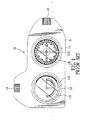
- a multifunction measuring device according to the present invention is shown to include a housing 2, a mounting seat 4, an orientation measuring unit, an inclination angle measuring unit, a mirror 7, a thermometer 8, and a hanging rope 9.
- the housing 2 has opposite front and rear sides 23, 24, opposite lateral ends 25, 26, and opposite top and bottom ends 27, 28.
- the front side 23 is formed with a front opening 231.
- the rear side 24 is formed with a rear opening 241 aligned coaxially with the front opening 231 in the front side 23.
- the lateral end 25 is formed with a first viewing hole 251, and the top end 27 is formed with a second viewing hole 271, as best shown in Figure 6 .
- the housing 2 includes complementary front and rear housing parts 21, 22 connected to each other using a plurality of screw fasteners 100.
- the front housing part 21 is formed with the front opening 231.
- the rear housing 22 is formed with the rear opening 241.
- the front housing 21 cooperates with the rear housing 22 to define the first and second viewing holes 251, 271, and an insertion groove 29 (see Figure 6 ) therebetween.
- the insertion groove 29 extends downward from the top end 27 of the housing 2, and is disposed adjacent to the lateral end 26 of the housing 2.
- the insertion groove 29 is defined by a U-shaped groove-defining wall 291.
- the U-shaped groove-defining wall 291 includes opposite front and rear wall portions 291, 292, wherein the front wall portion 291 is a part of the front housing 21, and the rear wall portion 292 is a part of the rear housing 22.
- Each of the front and rear wall portions 291, 292 is formed with a plurality of positioning holes 2911, 2921.
- a transparent dust-proof piece 20 is mounted in the housing 2 for covering the second viewing hole 271 in the top end 27 of the housing 2.
- the mounting seat 4 is mounted fixedly in the housing 2, and is disposed coaxially with the front and rear openings 231, 241 in the housing 2.
- the mounting seat 4 includes a barrel body 42 connected to the rear housing part 22 using a plurality of screw fasteners 101 (see Figure 2 ), and a partition plate 41 mounted in the barrel body 42 and cooperating with the barrel body 42 to define a front receiving space 43 and a rear receiving space 44.
- the barrel body 42 has opposite front and rear end 421, 422.
- the front end 421 of the barrel body 42 is formed with a front notch 4211 that is in spatial communication with the front receiving space 43 and that is aligned with the first viewing hole 251 in the housing 2.
- the rear end 422 of the barrel body 42 is formed with a rear notch 4221 that is in spatial communication with the rear receiving space 44 and that is aligned with the second viewing hole 271 in the housing 2.
- the orientation measuring unit includes an orientation compass 51, a connecting seat 52, and a first magnification member.
- the orientation compass 51 is mounted in the mounting seat 4, and is received in the front receiving space 43 in the mounting seat 4.
- the orientation compass 51 has a compass scale 511 exposed through the front opening 231 in the housing 2, and a first scale ring 512 visible through the first viewing hole 251 and the front notch 4211 in the barrel body 42 of the mounting seat 4.
- the connecting seat 52 is mounted fixedly in the housing 2, and is disposed adjacent to the mounting seat 4 .
- the connecting seat 52 is formed with a through hole 521 that is aligned with the front notch 4211 in the barrel body 42 of the mounting seat 4 and the first viewing hole 251 in the housing 2.
- the through hole 521 is a screw hole.
- the first magnification member includes a tubular body 53, a first magnifying lens 54, a washer 55, an anchoring ring 4, and a protection cover 57.
- the tubular body 53 has a connecting end portion 531 with an annular outer thread surface extending into the through hole 521 in the connecting seat 52 and connected movably to the connecting seat 52, and an enlarged operating end portion 532 opposite to the connecting end portion 531 and extending outward of the housing 2 through the first viewing hole 251 (see Figure 6 ).
- the first magnifying lens 54 is mounted in the tubular body 53, and is received in the operating end portion 532 of the tubular body 53.
- the washer 55 is sleeved on the connecting end portion 531 of the tubular body 53.
- the anchoring ring 56 is disposed fittingly in the operating end portion 532 of the tubular body 53 for anchoring the first magnifying lens 54 in the tubular body 53.
- the protection cover 57 has a pivot end 571 connected pivotally to the housing 1 using a pivot rod 570 fixed in the housing 1, and a cover end 572 opposite to the pivot end 571.
- the cover end 572 of the protection cover 57 is in the form of a plug.
- the protection cover 57 is operable so that the cover end 572 plugged into and connected to the operating end portion 532 of the tubular body 53 so as to cover the first magnifying lens 54 in the tubular body 53 (see Figure 3 ).
- the cover end 572 of the protection cover 57 is moved away from the operating end portion 532 of the tubular body 53. Thereafter, the operating end portion 532 is rotated to adjust a distance between the first magnifying lens 54 and the first scale ring 512, i.e., an adequate focal distance for a user's eye, so as to enable the first magnifying lens 54 to adequately magnify scales on the first scale ring 512 of the orientation compass 51 such that orientation information of the user's location can be clearly read from the first scale ring 512 of the orientation compass 51 by the user.
- a distance between the first magnifying lens 54 and the first scale ring 512 i.e., an adequate focal distance for a user's eye
- the inclination angle measuring unlit includes an inclinometer 61, and a second magnification member.
- the inclinometer 61 is mounted in the mounting seat 4, and is received in the rear receiving space 44 in the mounting seat 4.
- the inclinometer 61 has an inclinometer scale 611 exposed through the rear opening 241 in the housing 2, and a second scale ring 612 visible through the second viewing hole 271 and the rear notch 4221 in the barrel body 42 of the mounting seat 4.
- the second magnification member includes a lens-mounting seat 62, a second magnifying lens 63, and a protection cover 64.
- the lens-mounting seat 62 is mounted on the housing 2, and is movable up and down relative to the housing 2.
- the lens-mounting seat 62 includes a vertical insertion block 621 insertedmovably into the insertion groove 29 in the housing 2, and a horizontal extension plate 622 connected to the vertical insertion block 621 and disposed above the top end 27 of the housing 2.
- the vertical insertion block 621 has front and rear ends 6211 each formed with an engaging protrusion 6212 that engages releasably a selected one of the positioning holes 2911, 2912 in a corresponding one of the front and rear wall portions 291, 292 of the groove-defining wall 290 of the housing 2, thereby positioning the lens-mounting seat 62 in a desired position, as shown in Figures 5 and 8 , wherein Figure 5 illustrates the lens-mounting seat 62 when positioned in a retracted position, and Figure 8 illustrates the lens-mounting seat 62 when positioned in a raised position.
- the vertical insertion block 621 has a bottom end 6213 formed with two upward extending slots 6214.
- the horizontal extension plate 622 is formed with a lens-mounting hole 6221 aligned with the second viewing hole 271 in the housing 2 and mounted with the second magnifying lens 63 therein.
- the lens-mounting seat 62 further has an annular engaging flange 6222 extending upward from the horizontal extension plate 622 and surrounding the lens-mounting holes 6221.
- the protection cover 64 has a pivot end 641 connected pivotally to the lens-mounting seat 62 using a pivot rod 640 fixed in the lens-mounting seat 62, and a cap end 642 opposite to the pivot end 641.
- the protection cover 64 is operable so that the cap end 642 is connected to the annular engaging flange 6222 of the horizontal extension plate 622 so as to cover the second magnifying lens 63 in the lens-mounting seat 62 (see Figure 4 ).
- the cap end 642 of the protection cover 64 is moved away from the annular engaging flange 6222 of the lens-mounting seat 62. Thereafter, the lens-mounting seat 62 is moved up or down to adjust a distance between the second magnifying lens 63 and the second scale ring 612 of the inclinometer 61, i.e., an adequate focal distance for a user's eye, so as to enable the second magnifying lens 63 to adequately magnify scales on the second scale ring 612 of the inclinometer 61 such that inclination angle information of the user's location can be clearly read from the second scale ring 612 of the inclinometer 61 by the user.
- a distance between the second magnifying lens 63 and the second scale ring 612 of the inclinometer 61 i.e., an adequate focal distance for a user's eye
- the mirror 7 is mounted on the lateral end 26 of the housing 2, and is received in a mirror-receiving groove in the lateral end 26 of the housing 2, as shown in Figures 4 and 7 .
- the mirror 7 is regarded as a reflector for field help.
- thermometer 8 is mounted on the bottom end 28 of the housing 2, and is received in a thermometer-receiving groove 281 in the bottom end 28 of the housing 2, as shown in Figure 9 .
- the hanging rope 9 is connected to the housing 2 using a connecting rod 90 mounted in the housing 2, and extends outward of the housing 2, thereby facilitating carrying of the multi-function measuring device.
- the multifunction measuring device of the present invention since the orientation compass 51 and the inclinometer 61 are mounted respectively in the front and rear sides 23, 24 of the housing 2, the multifunction measuring device of the present invention has a compact size, and is convenient to carry.
Abstract
A multifunction measuring device includes: an orientation compass (51) and an inclinometer (61) mounted in a mounting seat (4) and disposed in a housing (2) so that the orientation compass (51) and the inclinometer (61) are respectively exposed through front and rear openings (231, 241) in the housing (2); a first magnification member disposed in the housing (2), connected movably to a connecting seat (52) fixed in the housing (2), and including a first magnifying lens (54) aligned with a first viewing hole (251) in the housing (2); and a second magnification member connected movably to the housing (2), and including a second magnifying lens (63) aligned with a second viewing hole (271) in the housing (2).
Description
- The invention relates to a measuring instrument, and more particularly to a multifunction measuring device.
- Referring to
Figure 1 , aconventional measuring instrument 10 is shown to include: ahousing 11; aninclinometer 12 and anorientation compass 13 mounted to a mounting surface of thehousing 11; a first magnification-adjustingmember 14 mounted to thehousing 11, and operable to adjust an adequate focal distance for a user's eye so as to enable a built-in first magnifying lens (not shown) to adequately magnify scales on ascale ring 122 of theinclinometer 12 such that inclination angle information of the user's location can be clearly read from thescale ring 122 by the user; and a second magnification-adjustingmember 15 mounted to thehousing 11, and operable to adjust an adequate focal distance for a user's eye so as to enable a built-in second magnifying lens (not shown) to adequately magnify scales on ascale ring 132 of theorientation compass 13 such that orientation information of the user's location can be clearly read from thescale ring 132 by the user. Alternatively, the inclination angle information of the user's location can also be read from aninclinometer scale 121 of theinclinometer 12, and the orientation information of the user's location can also be read from acompass scale 131 of theorientation compass 13. - However, since the
inclinometer 12 and theorientation compass 13 are mounted to the same mounting surface of thehousing 11, the conventionalmeasuring instrument 10 has a relatively large size in length, and is inconvenient to carry. - Therefore, an object of the present invention is to provide a multifunction measuring device that can overcome the aforesaid drawbacks of the prior art.
- According to the present invention, a multifunction measuring device of the present invention comprises:
- a housing having a front side formed with a front opening, a rear side formed with a rear opening that is aligned coaxially with the front opening, opposite lateral ends, one of which is formed with a first viewing hole, a top end formed with a second viewing hole, and a bottom end;
- a mounting seat mounted fixedly in the housing and disposed coaxially with the front and rear openings in the housing;
- an orientation measuring unit including
- an orientation compass mounted in the mounting seat, and having a compass scale exposed through the front opening in the housing, and a first scale ring visible through the first viewing hole in the housing,
- a connecting seat mounted fixedly in the housing, disposed adjacent to the mounting seat and formed with a through hole aligned with the first viewing hole in the housing, and
- a first magnification member including a tubular body, which has a connecting end portion extending into the through hole in the connecting seat and connected movably to the connecting seat, and an operating end portion opposite to the connecting end portion and extending outward of the housing through the first viewing hole, and a first magnifying lens mounted in the tubular body; and
- an inclination angle measuring unit including
- an inclinometer mounted in the mounting seat, and having an inclinometer scale exposed through the rear opening in the housing, and a second scale ring visible through the second viewing hole in the housing, and
- a second magnification member including a lens-mounting seat mounted on the housing and movable up and down relative to the housing, and a second magnifying lens mounted in the lens-mounting seat and disposed above the second viewing hole in the housing.
- Other features and advantages of the present invention will become apparent in the following detailed description of the preferred embodiment with reference to the accompanying drawings, of which:
-
Figure 1 is a schematic front view of a conventional measuring instrument; -
Figure 2 is an exploded perspective view showing the preferred embodiment of a multifunction measuring device according to the present invention; -
Figure 3 is an assembled front perspective view showing the preferred embodiment; -
Figure 4 is an assembled rearperspective view showing the preferred embodiment; -
Figure 5 is a partially sectional schematic side view illustrating the preferred embodiment when a lens-mounting seat is in a retracted position; -
Figure 6 is a front perspective view showing the preferred embodiment when in a state of use; -
Figures 7 is a rear perspective view showing the preferred embodiment when in the state of use; -
Figure 8 is a partially sectional schematic side view illustrating the preferred embodiment when the lens-mounting seat is in a raised position; and -
Figure 9 is a schematic bottom view showing the preferred embodiment. - Referring to
Figures 2 to 4 , the preferred embodiment of a multifunction measuring device according to the present invention is shown to include ahousing 2, amounting seat 4, an orientation measuring unit, an inclination angle measuring unit, amirror 7, athermometer 8, and ahanging rope 9. - The
housing 2 has opposite front andrear sides lateral ends bottom ends front side 23 is formed with a front opening 231. Therear side 24 is formed with arear opening 241 aligned coaxially with the front opening 231 in thefront side 23. Thelateral end 25 is formed with afirst viewing hole 251, and thetop end 27 is formed with asecond viewing hole 271, as best shown inFigure 6 . - In this embodiment, the
housing 2 includes complementary front andrear housing parts screw fasteners 100. Thefront housing part 21 is formed with the front opening 231. Therear housing 22 is formed with therear opening 241. Thefront housing 21 cooperates with therear housing 22 to define the first andsecond viewing holes Figure 6 ) therebetween. Theinsertion groove 29 extends downward from thetop end 27 of thehousing 2, and is disposed adjacent to thelateral end 26 of thehousing 2. In addition, referring further toFigure 5 , theinsertion groove 29 is defined by a U-shaped groove-definingwall 291. The U-shaped groove-definingwall 291 includes opposite front andrear wall portions front wall portion 291 is a part of thefront housing 21, and therear wall portion 292 is a part of therear housing 22. Each of the front andrear wall portions positioning holes proof piece 20 is mounted in thehousing 2 for covering thesecond viewing hole 271 in thetop end 27 of thehousing 2. - The
mounting seat 4 is mounted fixedly in thehousing 2, and is disposed coaxially with the front andrear openings housing 2. In this embodiment, themounting seat 4 includes abarrel body 42 connected to therear housing part 22 using a plurality of screw fasteners 101 (seeFigure 2 ), and a partition plate 41 mounted in thebarrel body 42 and cooperating with thebarrel body 42 to define a front receiving space 43 and arear receiving space 44. Thebarrel body 42 has opposite front andrear end front end 421 of thebarrel body 42 is formed with afront notch 4211 that is in spatial communication with the front receiving space 43 and that is aligned with thefirst viewing hole 251 in thehousing 2. Therear end 422 of thebarrel body 42 is formed with arear notch 4221 that is in spatial communication with therear receiving space 44 and that is aligned with thesecond viewing hole 271 in thehousing 2. - The orientation measuring unit includes an
orientation compass 51, a connecting seat 52, and a first magnification member. - The
orientation compass 51 is mounted in themounting seat 4, and is received in the front receiving space 43 in themounting seat 4. Theorientation compass 51 has acompass scale 511 exposed through the front opening 231 in thehousing 2, and afirst scale ring 512 visible through thefirst viewing hole 251 and thefront notch 4211 in thebarrel body 42 of themounting seat 4. - The connecting seat 52 is mounted fixedly in the
housing 2, and is disposed adjacent to themounting seat 4 . The connecting seat 52 is formed with athrough hole 521 that is aligned with thefront notch 4211 in thebarrel body 42 of themounting seat 4 and thefirst viewing hole 251 in thehousing 2. In this embodiment, thethrough hole 521 is a screw hole. - The first magnification member includes a
tubular body 53, a firstmagnifying lens 54, awasher 55, ananchoring ring 4, and aprotection cover 57. Thetubular body 53 has a connecting end portion 531 with an annular outer thread surface extending into the throughhole 521 in the connecting seat 52 and connected movably to the connecting seat 52, and an enlargedoperating end portion 532 opposite to the connecting end portion 531 and extending outward of thehousing 2 through the first viewing hole 251 (seeFigure 6 ). The firstmagnifying lens 54 is mounted in thetubular body 53, and is received in theoperating end portion 532 of thetubular body 53. Thewasher 55 is sleeved on the connecting end portion 531 of thetubular body 53. The anchoringring 56 is disposed fittingly in theoperating end portion 532 of thetubular body 53 for anchoring the firstmagnifying lens 54 in thetubular body 53. Theprotection cover 57 has apivot end 571 connected pivotally to the housing 1 using apivot rod 570 fixed in the housing 1, and acover end 572 opposite to thepivot end 571. In this embodiment, thecover end 572 of theprotection cover 57 is in the form of a plug. Theprotection cover 57 is operable so that thecover end 572 plugged into and connected to theoperating end portion 532 of thetubular body 53 so as to cover the firstmagnifying lens 54 in the tubular body 53 (seeFigure 3 ). - In use, as best shown in
Figure 6 , thecover end 572 of theprotection cover 57 is moved away from theoperating end portion 532 of thetubular body 53. Thereafter, theoperating end portion 532 is rotated to adjust a distance between the firstmagnifying lens 54 and thefirst scale ring 512, i.e., an adequate focal distance for a user's eye, so as to enable the firstmagnifying lens 54 to adequately magnify scales on thefirst scale ring 512 of theorientation compass 51 such that orientation information of the user's location can be clearly read from thefirst scale ring 512 of theorientation compass 51 by the user. - The inclination angle measuring unlit includes an
inclinometer 61, and a second magnification member. - The
inclinometer 61 is mounted in themounting seat 4, and is received in the rearreceiving space 44 in themounting seat 4. Theinclinometer 61 has aninclinometer scale 611 exposed through therear opening 241 in thehousing 2, and asecond scale ring 612 visible through thesecond viewing hole 271 and therear notch 4221 in thebarrel body 42 of themounting seat 4. - The second magnification member includes a lens-
mounting seat 62, a secondmagnifying lens 63, and aprotection cover 64. The lens-mounting seat 62 is mounted on thehousing 2, and is movable up and down relative to thehousing 2. - In this embodiment, the lens-mounting
seat 62 includes avertical insertion block 621 insertedmovably into theinsertion groove 29 in thehousing 2, and ahorizontal extension plate 622 connected to thevertical insertion block 621 and disposed above thetop end 27 of thehousing 2. Thevertical insertion block 621 has front andrear ends 6211 each formed with an engagingprotrusion 6212 that engages releasably a selected one of the positioning holes 2911, 2912 in a corresponding one of the front andrear wall portions wall 290 of thehousing 2, thereby positioning the lens-mountingseat 62 in a desired position, as shown inFigures 5 and8 , whereinFigure 5 illustrates the lens-mountingseat 62 when positioned in a retracted position, andFigure 8 illustrates the lens-mountingseat 62 when positioned in a raised position. In addition, as shown inFigures 5 and8 , thevertical insertion block 621 has abottom end 6213 formed with two upward extendingslots 6214. Thehorizontal extension plate 622 is formed with a lens-mountinghole 6221 aligned with thesecond viewing hole 271 in thehousing 2 and mounted with thesecond magnifying lens 63 therein. The lens-mountingseat 62 further has an annularengaging flange 6222 extending upward from thehorizontal extension plate 622 and surrounding the lens-mountingholes 6221. - The
protection cover 64 has apivot end 641 connected pivotally to the lens-mountingseat 62 using apivot rod 640 fixed in the lens-mountingseat 62, and acap end 642 opposite to thepivot end 641. Theprotection cover 64 is operable so that thecap end 642 is connected to the annularengaging flange 6222 of thehorizontal extension plate 622 so as to cover thesecond magnifying lens 63 in the lens-mounting seat 62 (seeFigure 4 ). - In use, as best shown in
Figure 7 , thecap end 642 of theprotection cover 64 is moved away from the annularengaging flange 6222 of the lens-mountingseat 62. Thereafter, the lens-mountingseat 62 is moved up or down to adjust a distance between thesecond magnifying lens 63 and thesecond scale ring 612 of theinclinometer 61, i.e., an adequate focal distance for a user's eye, so as to enable thesecond magnifying lens 63 to adequately magnify scales on thesecond scale ring 612 of theinclinometer 61 such that inclination angle information of the user's location can be clearly read from thesecond scale ring 612 of theinclinometer 61 by the user. - The
mirror 7 is mounted on thelateral end 26 of thehousing 2, and is received in a mirror-receiving groove in thelateral end 26 of thehousing 2, as shown inFigures 4 and7 . When the multifunction measuring device is used in outdoor applications, themirror 7 is regarded as a reflector for field help. - The
thermometer 8 is mounted on thebottom end 28 of thehousing 2, and is received in a thermometer-receivinggroove 281 in thebottom end 28 of thehousing 2, as shown inFigure 9 . - The hanging
rope 9 is connected to thehousing 2 using a connectingrod 90 mounted in thehousing 2, and extends outward of thehousing 2, thereby facilitating carrying of the multi-function measuring device. - In sum, since the
orientation compass 51 and theinclinometer 61 are mounted respectively in the front andrear sides housing 2, the multifunction measuring device of the present invention has a compact size, and is convenient to carry.
Claims (11)
- A multifunction measuring device characterized by:a housing (2) having a front side (23) formed with a front opening (231), a rear side (24) formed with a rear opening (241) that is aligned coaxially with said front opening (231), opposite lateral ends (25, 26), one of which is formed with a first viewing hole (251), a top end (27) formed with a second viewing hole (271), and a bottom end (28);a mounting seat (4) mounted fixedly in said housing (2) and disposed coaxially with said front and rear openings (231, 241) in said housing (2);an orientation measuring unit including
an orientation compass (51) mounted in said mounting seat (4), and having a compass scale (511) exposed through said front opening (231) in said housing (2), and a first scale ring (512) visible through said first viewing hole (251) in said housing (2),
a connecting seat (52) mounted fixedly in said housing (2), disposed adjacent to said mounting seat (4) and formed with a through hole (521) aligned with said first viewing hole (251) in said housing (2), and
a first magnification member including a tubular body (53), which has a connecting end portion (531) extending into said through hole (521) in said connecting seat (52) and connected movably to said connecting seat (52), and an operating end portion (532) opposite to said connecting end portion (531) and extending outward of said housing (2) through said first viewing hole (251), and a first magnifying lens (54) mounted in said tubular body (53); andan inclination angle measuring unit including
an inclinometer (61) mounted in said mounting seat (4), and having an inclinometer scale (611) exposed through said rear opening (271) in said housing (2), and a second scale ring (612) visible through said second viewing hole (271) in said housing (2), and
a second magnification member including a lens-mounting seat (62) mounted on said housing (2) and movable up and down relative to said housing (2), and a second magnifying lens (63) mounted in said lens-mounting seat (62) and disposed above said second viewing hole (271) in said housing (2). - The multifunction measuring device as claimed in Claim 1, characterized in that:said housing (2) includes complementary front and rear housing parts (21, 22), said front housing part (21) being forming with said front opening (231), said second housing part (22) being formed with said rear opening (241), said front housing part (21) cooperating with said rear housing part (22) to define said first and second viewing holes (251, 271), and an insertion groove (29) therebetween, said insertion groove (29) extending downward from said top end (27) of said housing (2), and being disposed adjacent to the other one of said lateral ends (26) of said housing (2); andsaid lens-mounting seat (62) of said second magnification member includes a vertical insertion block (621) inserted movably into said insertion groove (29) in said housing (2), and a horizontal extension plate (622) connected to said vertical insertion block (621), disposed above said top end (27) of said housing (2) and mounted with said second magnifying lens (63) therein.
- The multifunction measuring device as claimed in Claim 2, further characterized in that said second magnification member of said inclination angle measuring unit further includes a protection cover (64) connected pivotally to said lens-mounting seat (62) and operable to connect said horizontal extension plate (622) so as to cover said second magnifying lens (63).
- The multifunction measuring device as claimed in Claim 2, further characterize in that:said vertical insertion block (621) of said lens-mounting seat (62) of said second magnification member having front and rear ends (6211) each formed with an engaging protrusion (6212); andsaid housing (2) further has a U-shaped groove-defining wall (290) defining said insertion groove (29) in said housing (2) and including opposite front and rear wall portions (291, 292) each formed with a plurality of positioning holes (2911, 2921), said engaging protrusion (6212) of each of said front and rear ends (6211) of said vertical insertion block (621) engaging releasably a selected one of said positioning holes (2911, 2921) in a corresponding one of said front and rear wall portions (291, 292) of said groove-defining wall (290) of said housing (2), thereby positioning said lens-mounting seat (62) in a desired position.
- The multifunction measuring device as claimed in Claim 4, further characterized in that said vertical insertion block (621) of said lens-mounting seat (62) has a bottom end ((6213) formed with two upward extending slots (6214).
- The multifunction measuring device as claimed in Claim 1, further characterized by a transparent dust-proof piece (20) mounted in said housing (2) for covering said second viewing hole (271) in said housing (2).
- The multifunction measuring device as claimed in Claim 1, characterized in that said first magnification member of said orientation measuring unit further includes a protection cover (57) connected pivotally to said housing (2) and operable to connect said operating end portion (532) of said tubular body (53) so as to cover said first magnifying lens (54) in said tubular body (53).
- The multifunction measuring device as claimed in Claim 1, characterized in that said mounting seat (4) includes a barrel body (42) and a partition plate (41) mounted in said barrel body (42) and cooperating with said barrel body (42) to define a front receiving space (43) for receiving said orientation compass (51), and a rear receiving space (44) for receiving said inclinometer (61), said barrel body (42) having a front end (421) formed with a front notch (4211) that is in spatial communication with said front receiving space (43) and that is aligned with said through hole (521) in said connecting seat (52) of said orientation measuring unit, and a rear end (422) formed with a rear notch (4221) that is in spatial communication with said rear receiving space (44) and that is aligned with said second viewing hole (271) in said housing (2).
- The multifunction measuring device as claimed in Claim 1, further characterized by a mirror (7) mounted on the other one of said lateral ends (26) of said housing (2).
- The multifunction measuring device as claimed in Claim 1, further characterized by a thermometer (8) mounted on said bottom end (28) of said housing (2).
- The multifunction measuring device as claimed in Claim 1, further characterized by a hanging rope (9) connected to said housing (2) and extending outward of said housing (2).
Applications Claiming Priority (1)
| Application Number | Priority Date | Filing Date | Title |
|---|---|---|---|
| TW100148384A TW201326756A (en) | 2011-12-23 | 2011-12-23 | Multifunction measuring device |
Publications (1)
| Publication Number | Publication Date |
|---|---|
| EP2607842A2 true EP2607842A2 (en) | 2013-06-26 |
Family
ID=45999579
Family Applications (1)
| Application Number | Title | Priority Date | Filing Date |
|---|---|---|---|
| EP12160417.7A Withdrawn EP2607842A2 (en) | 2011-12-23 | 2012-03-20 | Multifunction measuring device |
Country Status (3)
| Country | Link |
|---|---|
| US (1) | US8640351B2 (en) |
| EP (1) | EP2607842A2 (en) |
| TW (1) | TW201326756A (en) |
Families Citing this family (8)
| Publication number | Priority date | Publication date | Assignee | Title |
|---|---|---|---|---|
| CN203117501U (en) * | 2013-01-10 | 2013-08-07 | 虔茂有限公司 | Mobile type lens structure |
| US9851203B2 (en) | 2014-06-27 | 2017-12-26 | Real Science Innovations, LLC | Apparatus and methods for measuring strike and dip, trend and plunge, bearings, and inclination |
| US9885572B2 (en) | 2014-11-13 | 2018-02-06 | Milwaukee Electric Tool Corporation | Level including a slot for receiving a straight edge |
| USD830862S1 (en) | 2015-06-26 | 2018-10-16 | Real Science Innovations, LLC | Geological compass |
| US10281274B2 (en) | 2016-06-27 | 2019-05-07 | Milwaukee Electric Tool Corporation | Level and level-straightedge system |
| TWI727403B (en) * | 2019-08-22 | 2021-05-11 | 船慶機械工業股份有限公司 | North needle device |
| CN113124830A (en) * | 2021-04-09 | 2021-07-16 | 广州得尔塔影像技术有限公司 | Method and equipment for testing imaging optical gradient of camera module |
| CN113295067B (en) * | 2021-05-21 | 2022-12-23 | 辽宁工程技术大学 | Portable mechanical design uses multi-functional measuring device |
Family Cites Families (8)
| Publication number | Priority date | Publication date | Assignee | Title |
|---|---|---|---|---|
| US4188729A (en) * | 1978-11-20 | 1980-02-19 | Peterson Edwin E | Scribing protractor |
| US4485825A (en) * | 1982-07-27 | 1984-12-04 | Medicor Muvek | Instrument for measuring positions and displacements of joints and spinal column (arthrospinometer) |
| US6357128B1 (en) * | 1998-07-27 | 2002-03-19 | The Brunton Company | Low profile compass with removable protective cover and magnetic bull's eye alignment system |
| US6243660B1 (en) * | 1999-10-12 | 2001-06-05 | Precision Navigation, Inc. | Digital compass with multiple sensing and reporting capability |
| US20020104224A1 (en) * | 2001-02-08 | 2002-08-08 | Barker David D. | Right reading magnetic compass |
| US6701631B1 (en) * | 2002-12-23 | 2004-03-09 | Inco Limited | Convertible directional azimuth and dip measuring modular compass and method |
| US8006397B2 (en) * | 2009-03-13 | 2011-08-30 | Schubert Dick S | Remote leveling and positioning system and method |
| KR101164411B1 (en) * | 2012-03-19 | 2012-07-12 | 한국지질자원연구원 | Apparatus for measuring strike and dip and auxiliary apparatus for measuring strike and dip |
-
2011
- 2011-12-23 TW TW100148384A patent/TW201326756A/en unknown
-
2012
- 2012-03-20 EP EP12160417.7A patent/EP2607842A2/en not_active Withdrawn
- 2012-03-26 US US13/430,205 patent/US8640351B2/en active Active
Non-Patent Citations (1)
| Title |
|---|
| None |
Also Published As
| Publication number | Publication date |
|---|---|
| TWI438406B (en) | 2014-05-21 |
| TW201326756A (en) | 2013-07-01 |
| US20130160311A1 (en) | 2013-06-27 |
| US8640351B2 (en) | 2014-02-04 |
Similar Documents
| Publication | Publication Date | Title |
|---|---|---|
| US8640351B2 (en) | Multifunction measuring device | |
| KR101392562B1 (en) | Portable terminal case with exchangeable module | |
| US9131132B2 (en) | Phone camera mount | |
| US20080198447A1 (en) | Microscope with Adjustable Stage | |
| TWI627486B (en) | A device with replaceable lens module | |
| EP3288244A1 (en) | Holding case for installing handset add-on lens, handset external lens connection structure, and handset installation case | |
| CN210707834U (en) | Underwater detection device | |
| JP2015046074A (en) | Protective cover | |
| KR101531042B1 (en) | Lantern | |
| US20040130657A1 (en) | Digital camera | |
| JP2006169669A (en) | Multifunctional magnifying glass device usable by attached to hat | |
| CN105431774A (en) | Holder for a mobile device to capture images | |
| JP6037650B2 (en) | Remote viewing device | |
| TWM395190U (en) | Camera lens Adapting rack | |
| JP6016592B2 (en) | Case for portable information terminal | |
| CN207992551U (en) | The micro-telescope of hand-held terminal device viewing can be connected | |
| KR101402727B1 (en) | Foldable mount for image magnifier | |
| CN218820118U (en) | Light supplement lamp device with support | |
| CN215116966U (en) | Novel digital microscope | |
| CN217236777U (en) | Automatic leveling instrument | |
| KR101473088B1 (en) | Electron magnifier | |
| CN211653294U (en) | Night vision device shell | |
| CN216870994U (en) | Camera expansion handle | |
| JPH1078194A (en) | Flexible magnifier | |
| CN217821081U (en) | Telescope |
Legal Events
| Date | Code | Title | Description |
|---|---|---|---|
| AK | Designated contracting states |
Kind code of ref document: A2 Designated state(s): AL AT BE BG CH CY CZ DE DK EE ES FI FR GB GR HR HU IE IS IT LI LT LU LV MC MK MT NL NO PL PT RO RS SE SI SK SM TR |
|
| AX | Request for extension of the european patent |
Extension state: BA ME |
|
| PUAI | Public reference made under article 153(3) epc to a published international application that has entered the european phase |
Free format text: ORIGINAL CODE: 0009012 |
|
| STAA | Information on the status of an ep patent application or granted ep patent |
Free format text: STATUS: THE APPLICATION IS DEEMED TO BE WITHDRAWN |
|
| 18D | Application deemed to be withdrawn |
Effective date: 20151001 |