EP2607561B1 - Verbesserter Aufhänger - Google Patents
Verbesserter Aufhänger Download PDFInfo
- Publication number
- EP2607561B1 EP2607561B1 EP12198114.6A EP12198114A EP2607561B1 EP 2607561 B1 EP2607561 B1 EP 2607561B1 EP 12198114 A EP12198114 A EP 12198114A EP 2607561 B1 EP2607561 B1 EP 2607561B1
- Authority
- EP
- European Patent Office
- Prior art keywords
- flange portion
- joist hanger
- joist
- top flange
- back flange
- Prior art date
- Legal status (The legal status is an assumption and is not a legal conclusion. Google has not performed a legal analysis and makes no representation as to the accuracy of the status listed.)
- Active
Links
- 238000005452 bending Methods 0.000 description 3
- 238000009432 framing Methods 0.000 description 2
- 238000009434 installation Methods 0.000 description 2
- 239000007787 solid Substances 0.000 description 2
- 230000001154 acute effect Effects 0.000 description 1
- 230000004075 alteration Effects 0.000 description 1
- 230000001010 compromised effect Effects 0.000 description 1
- 238000010276 construction Methods 0.000 description 1
- 230000004048 modification Effects 0.000 description 1
- 238000012986 modification Methods 0.000 description 1
- 239000011120 plywood Substances 0.000 description 1
- 239000002023 wood Substances 0.000 description 1
Images


Classifications
-
- E—FIXED CONSTRUCTIONS
- E04—BUILDING
- E04B—GENERAL BUILDING CONSTRUCTIONS; WALLS, e.g. PARTITIONS; ROOFS; FLOORS; CEILINGS; INSULATION OR OTHER PROTECTION OF BUILDINGS
- E04B1/00—Constructions in general; Structures which are not restricted either to walls, e.g. partitions, or floors or ceilings or roofs
- E04B1/18—Structures comprising elongated load-supporting parts, e.g. columns, girders, skeletons
- E04B1/26—Structures comprising elongated load-supporting parts, e.g. columns, girders, skeletons the supporting parts consisting of wood
- E04B1/2604—Connections specially adapted therefor
- E04B1/2612—Joist hangers
Definitions
- the present invention relates to joist hangers used to connect two members such as I-joists, and in particular to multi-functional joist hangers that are adjustable to provide for variations in the size/shape of the connected members.
- an I-joist 1, 3 comprises two main parts, the web 5 and flanges 7, 9.
- the web 5 is sandwiched between a top 7 and bottom flange 9, creating the "I" shape.
- the flange 7, 9 can be made from laminated veneer lumber or solid wood finger-jointed together for ultimate strength. It is then grooved on one side to receive the web 5.
- the web 5 is typically made from plywood, laminated veneer lumber, or oriented strand board.
- joist hangers are frequently used to typically connect two joists, or a joist with any other support structure, at a 90 degree angle. However, it may be required to connect the joists at any other desired angle. To form such a connection, the joist hanger is either face-fixed or top-fixed to the support provided by another joist or support structure. GB 2 047 320 A and US 3 036 347 A describe examples of such hangers.
- Figure 1 (a) shows two I-joists 1 and 3 connected at a 90 degree angle, wherein I-joist 1 is face-fixed to a side portion of I-joist 3 via a typical face-fix joist hanger 11. Face-fixing hangers are only fixed (e.g. nailed) to a side surface of the support via its side flanges 12.
- a bracket 13 connected to the side flanges 12 receives and supports joist 1, wherein the bracket is usually fixed to the joist flanges 14 and 15.
- Figure 1 (b) shows two I-joists 1, 3 connected at a 90 degree angle, wherein I-joist 1 is top-fixed to I-joist 3 via a typical top-fix joist hanger 16.
- Top-fixing hangers comprise top flanges 18 that sit on a top surface 20 of the support structure, e.g. I-joist 3, with nails being passed through the top flange 18.
- Top-fixing hangers such as joist hanger 16 may be used for light/medium load applications using fewer fixings (e.g. nails) to allow a quick and easy installation. Face-fixing hangers, such as joist hanger 11, are often used for higher load applications using considerably more fixings (e.g. nails) making the installation more time consuming and expensive. Face-fixing hangers may also be used because it is simply impractical or undesirable to have a top flange 18 located on the top surface 20 of the support structure, e.g. I-joist 3.
- hanger such as joist hangers 11 and 16
- the top flange portion is pre-formed (L-shape or U-shape) and does not allow for any variations in joist depth, position or support joist width.
- a joist hanger according to claim 1.
- the joist hanger comprising:
- At least one top fixing and at least one face fixing are locateable into a support structure through the elongated aperture.
- the support structure may be of variable depth dimension whilst still being suitable for attachment of the hanger due to the variable location of the articulation axis of the hanger.
- said at least one top flange portion may comprise a plurality of longitudinally elongated fixing apertures arranged in parallel or angled relative to one another.
- said top flange portion is adapted to bend about said articulation axis in a region defined by the length of said at least one longitudinally elongated fixing aperture.
- one joist hanger accommodates either face-fixing or top-fixing, wherein the selectively moveable top flange ensures a snug fit with the top surface of the support structure, even in the event that the top surface of the support structure is not perpendicular to its front surface.
- the top flange is aligned exactly with the top surface of the support structure.
- the joist hanger of the present invention provides the advantage that the top surface of the joist can be accurately aligned with the top surface of the support structure.
- the at least one longitudinally elongated fixing aperture provides a limited region within which the top flange may bend at the selected articulation axis about the edge of the support structure therefore providing a joist hanger depth that exactly matches the depth required to accurately align the top surfaces of the joist and support structure (which may be another joist or beam, for example).
- the at least one longitudinally elongated fixing aperture ensures that fixings, such as nails, can be placed through the top flange portion as well as through the back flange portion irrespective of the final joist hanger depth.
- providing a plurality of longitudinally elongated apertures allows for a variety of fixing positions on the I-joist and support structure.
- three longitudinally elongated fixing apertures may be arranged in parallel or angled relative to one another within the at least one top flange portion therefore providing optimized location for the fixings.
- the joist hanger of the present invention provides improved adaptability to variations in shape and size of the support structure and depth of the connected joists. Also, the multi-functional joist hanger (adjustable, top-fixing, face-fixing) provides the advantage of minimizing the cost for initial acquisition, because one joist hanger may be used for various applications and for a range of joist depths.
- said top flange portion may be coplanar with respect to said at least one back flange portion when in said face-fixing position.
- said top flange portion may adjoin said at least one back flange portion in a plane substantially perpendicular to the plane including said back flange portion when in said top-fixing position. It will be understood that in the top-fixing position, the top flange portion is bent relative to the back flange portion about the articulation axis of the hanger.
- Said at least one back flange portion may adjoin said respective at least one of said two side portions in a plane non-coplanar to planes including said two side portions. Most specifically, said at least one back flange portion may adjoin said respective at least one of said two side portions in a plane substantially perpendicular to planes including said two side portions.
- the at least one back flange portion may include first and second back flange portions each adjoined to one of said two side portions, respectively.
- said first and second back flange portion may extend laterally outward from respective side portions.
- This provides the advantage of minimizing stress related rotation of the joist with respect to the support structure it is connected to.
- said top flange portion may be detachable from said at least one back flange portion allowing the joist hanger to be limited to face fixing only. More specifically, the top flange portion may be detachable from said at least one back flange portion at the articulation axis. In this way, the top flange portion and the at least one back flange portion are separable from one another along the articulation axis of the hanger.
- the joist hanger further comprises at least one recess transversely aligned to and in a region defined by a length of said longitudinally elongated fixing aperture, and adapted to provide a predetermined crease line for said top flange portion.
- the predetermined crease line forms the articulation axis of the hanger.
- the at least one recess may be located at or proximal to a lower apex of the at least one longitudinally elongated fixing aperture.
- said at least one recess may be adapted to allow said at least one top flange portion to detach from respective said at least one back flange portion when moved back in a direction opposite to its top-fixing position.
- the top flange portion is bent about the articulation axis relative to the back flange portion in a direction opposite to that forming the top-fixing position.
- the joist hanger may further comprise a plurality of said recesses located at a plurality of predetermined positions within said region defined by the length of said at least one longitudinally elongated fixing aperture. More specifically, each of said plurality of recesses provides an articulation axis about which the top flange portion may be bent relative to the adjacent back flange portion.
- This provides the advantage of facilitating the movement of the top flange portion into its top-fixing position about predetermined crease lines which crease lines form articulation axes. More than one predetermined recess may be used to provide a predetermined selection of crease line positions and improve the ease of use and variation of position.
- the at least one top flange portion may comprise a first and second top flange portion adjoining said respective first and second back flange portion, each one of said first and second top flange portion may comprise said at least one longitudinally elongated fixing aperture and at least one articulation axis.
- the at least one top flange portion may comprise a first and second top flange portion adjoining said respective first and second back flange portion, each one of said first and second top flange portion may comprise said plurality of longitudinally elongated fixing apertures and at least one articulation axis.
- said side portions, at least one back flange portion and/or said at least one top flange portion may be provided with a plurality of additional fixing apertures arranged so as to optimize load capacity.
- At least part of said plurality of additional fixing apertures may be of circular shape.
- at least part of said plurality of additional fixing apertures may be of polygon shape.
- at least part of said plurality of additional fixing apertures may be of triangular shape.
- the circular shaped recesses such as nail holes, are advantageously located at the top and bottom flanges or the openweb of the I-joist allowing fixing without backer blocks.
- the polygonal or triangular recesses, such as nail holes, may be optional and may provide an enhanced load and a fully face-fixed hanger.
- the joist hanger may further comprise a base portion back plate upstanding from an edge of said base portion and coplanar with respect to said at least one back flange portion, and may be adapted to limit movement of a joist past said at least one back flange portion.
- the base portion back plate may be an upstand or maybe provided by one or more lugs upstanding from the edge of the base portion and substantially perpendicular thereto.
- the joist hanger may further comprise at least one edge flange adjoined along at least part of a longitudinal lateral edge of said at least one back flange portion. More specifically, the edge flange is located opposite the edge adjoining the side portion and may be folded forwardly of the back flange portion.
- the joist hanger may further comprise at least one edge flange adjoined along at least part of a transverse edge of said at least one back flange portion.
- the joist hanger may be substantially as herein described with reference to the accompanying drawings.
- a blank suitable for forming a joist hanger according to the first aspect of the invention is provided.
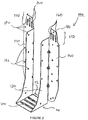
- the joist hanger comprises a bracket 110, including a base portion 120 and two parallel side portions 130 upstanding perpendicular from opposing edges of the base portion 120.
- Two back flange portions 140 are adjoined to longitudinal edges of respective side portions 130, extending laterally in a plane perpendicular to the planes defined by each one of the two side portions 130.
- a top flange portion 150 is adjoined to each one of the two back flange portions 140 at a location distal to the base portion 120.
- Each one of the two top flange portion 150 includes three longitudinally elongated fixing apertures 160, which define a region about which the top flange portion 150 is preferably bent, or "wiped over" about an articulation axis extending transversely of the top flange portion 150 and back flange portion 140, when moving the top flange portion 150 between its face-fixing position and top-fixing position.
- three longitudinally elongated fixing apertures 160 are positioned at acute angles with respect to each other.
- the longitudinally elongated fixing apertures 160 provide a region of least resistance when applying a bending force to the top flange portion 150.
- top flange portion 150 may be repeatedly moved about an articulation axis between its face-fixing position and top-fixing position without significantly compromising the structural integrity of the joist hanger 100.
- Additional fixing apertures 180, 182 may be provided on the side portions 130, the back flange portions 140 and the top flange portions 150, where they are strategically placed to fix the joist hanger 100 to the side and top surfaces of the joist flanges or, in case backer blocks are used, within a region of the joist web.
- the additional fixing apertures 180 for the joist flange are of circular shape, wherein the additional fixing apertures 182 for the joist web are of triangular shape.
- any suitable number, location and shape may be used for the additional fixing apertures 180, 182.
- the base portion 120 may include a base portion back plate 122 upstanding from an edge of the base portion and coplanar with the back flange portions 140.
- the base portion back plate 122 may be replaced by one or more lugs foldable out of the plane of the base portion to be upstanding substantially perpendicular therefrom.
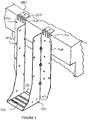
- the joist hanger 100 may be positioned and fixed at a side surface of another joist or support structure such that the top surfaces of the connecting joists are vertically aligned and the top flange portion 150 overlaps the edge of the side surface of the other joist or support structure.
- a force is then applied to the top flange portion 150 in order to bend ("wipe over") the top flange portion 150 at the edge 170 of the joists side surface (see Figure 3 ).
- Fixings, such as nails or screws or any other fixing elements, are placed through the additional fixing apertures 180, 182.
- fixings may only be placed into the top surface of the support structure through the longitudinally elongated fixing apertures 160 and/or the additional fixing apertures 180.
- the longitudinally elongated fixing apertures 160 ensure that the fixing for the top surface of the support structure can be optimally located irrespective of the depth of the front surface of the support structure, such as an I-joist.
- the top-fixed joist hanger 100 may be reused for face-fixing as well as another top-fixing by simply removing the fixings (e.g. nails) and moving the top flange portion 150 back to its face-fixing position.
- fixings e.g. nails
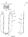
- the top flange portion 150 may be snapped off to ensure the joist hanger is only used for face-fixing. Snapping off the top flange portion 150 can be particularly useful when the joist hanger 100 has been reused and the top flange portion 150 has been moved frequently, and the structural integrity of the top flange portion is compromised.
- the top flange portion 150 is provided with an articulation axis in the form of a transverse recess 200 to facilitate the movement of the top flange portion and provide a predetermined crease line about which the top flange portion is bent with respect to the back flange portion 140.
- the transverse recess 200 assists the user when either bending or snapping off the top flange portion 150, therefore improving the ease of use.
- the transverse recess 200 is located at or proximal to a lower apex of the at least one longitudinally elongated fixing apertures 160.
- transverse recesses 202, 204 may be provided at different locations within the region of the top flange defined by the length of the longitudinally elongated fixing apertures 160. This provides additional articulation axes in the form of predetermined crease lines facilitating the movement and/or detachment of the top flange portion 150 at specific locations.
- the top flange portion 150 may be placed at the side surface of the support structure (e.g. joist) such that a predetermined transverse recess 200, 202, 204 is aligned with the edge of the support structure.
- the top flange portion 105 is then bent ("wiped over") at the predetermined transverse recess 200, 202, 204 and fixed to the top surface via fixings (e.g. nails).
- the top flange portion 150 is simply moved in a direction opposite its top-fixing position about a transverse recess 200, 202, 204 so that it snaps off at a predetermined location providing a clean cutting profile 210.
- edge flange may be provided along the longitudinal lateral edge and/or a transverse proximal edge of each one of the two back flange portions 140 in order to provide optimal stiffness to the joist hanger 100.
- the joist hanger 100 of the present invention may be manufactured by cutting or pressing a suitable blank and subsequently bending the pre-cut / pre-pressed sides to form the joist hanger 100.
Landscapes
- Engineering & Computer Science (AREA)
- Architecture (AREA)
- Physics & Mathematics (AREA)
- Electromagnetism (AREA)
- Civil Engineering (AREA)
- Structural Engineering (AREA)
- Floor Finish (AREA)
- Holders For Apparel And Elements Relating To Apparel (AREA)
Claims (18)
- Balkenschuh (100), umfassend:
einen Stützwinkel (110), der einen Basisabschnitt (120) und zwei im Wesentlichen parallele Seitenabschnitte (130) aufweist, die von gegenüberliegenden Kanten des Basisabschnitts (120) aufrecht nach oben vorstehen, wobei der Balkenschuh (100) ferner Folgendes umfasst:wenigstens einen hinteren Flanschabschnitt (140), der an wenigstens einen der beiden Seitenabschnitte (130) an einer Längskante des entsprechenden wenigstens einen der beiden Seitenabschnitte (130) angrenzt und der dazu ausgelegt ist, an einer vorderseitenfixierenden Fläche anzuliegen,wenigstens einen oberen Flanschabschnitt (150), der an den wenigstens einen hinteren Flanschabschnitt (140) an einer von dem Basisabschnitt (120) entfernten Kante angrenzt und zwischen einer vorderseitenfixierenden Position, in der der obere Flanschabschnitt (150) koplanar mit dem wenigstens einen hinteren Flanschabschnitt (140) ist, und einer vorderseitenfixierenden Position, in der der obere Flanschabschnitt (150) nicht koplanar mit dem wenigstens einen hinteren Flanschabschnitt (140) ist, bewegbar ist, ferner wenigstens eine in Längsrichtung gestreckte Fixierungsöffnung (160) und eine Gelenkachse, um die sich der obere Flanschabschnitt biegen kann, umfassend, wobei sich die Gelenkachse in Querrichtung des Balkenschuhs (100) zwischen dem oberen Flanschabschnitt (150) und dem hinteren Flanschabschnitt (140) erstreckt und in dem Bereich, der durch die Länge der wenigstens einen in Längsrichtung gestreckten Fixierungsöffnung (160) festgelegt ist, in ihrem Standort veränderbar ist,dadurch gekennzeichnet, dass die Gelenkachse in Form wenigstens einer Ausnehmung (200, 202, 204) vorliegt, die in Querrichtung an und in dem Bereich, der durch die Länge der wenigstens einen in Längsrichtung gestreckten Fixierungsöffnung (160) festgelegt ist, ausgerichtet ist und die dazu ausgelegt ist, eine vorgegebene Faltlinie für den oberen Flanschabschnitt (150) bereitzustellen. - Balkenschuh (100) nach Anspruch 1, wobei der wenigstens eine obere Flanschabschnitt (150) eine Vielzahl von in Längsrichtung gestreckten Fixierungsöffnungen (160) umfasst, die relativ zueinander parallel oder abgewinkelt angeordnet sind.
- Balkenschuh (100) nach einem der vorhergehenden Ansprüche, wobei der obere Flanschabschnitt (150) an den wenigstens einen hinteren Flanschabschnitt (140) in einer Ebene angrenzt, die im Wesentlichen senkrecht zu der Ebene verläuft, die in der oberseitenfixierenden Position den hinteren Flanschabschnitt (140) umfasst.
- Balkenschuh (100) nach einem der vorhergehenden Ansprüche, wobei der wenigstens eine hintere Flanschabschnitt (140) an den entsprechenden wenigstens einen der beiden Seitenabschnitte (130) in einer Ebene angrenzt, die nicht koplanar mit Ebenen ist, die die beiden Seitenabschnitte (130) umfassen.
- Balkenschuh (100) nach Anspruch 4, wobei der wenigstens eine hintere Flanschabschnitt (140) an den entsprechenden wenigstens einen der beiden Seitenabschnitte (130) in einer Ebene angrenzt, die im Wesentlichen rechtwinklig zu Ebenen verläuft, die die beiden Seitenabschnitte (130) umfassen.
- Balkenschuh (100) nach einem der vorhergehenden Ansprüche, wobei der wenigstens eine hintere Flanschabschnitt (140) einen ersten und einen zweiten hinteren Flanschabschnitt (140) umfasst, die jeweils an einen der beiden Seitenabschnitte (130) angrenzen.
- Balkenschuh (100) nach Anspruch 6, wobei sich der erste und der zweite hintere Flanschabschnitt (140) von den entsprechenden Seitenabschnitten (130) seitlich nach außen erstrecken.
- Balkenschuh (100) nach einem der vorhergehenden Ansprüche, wobei der obere Flanschabschnitt (150) von dem wenigstens einen hinteren Flanschabschnitt (140) gelöst werden kann.
- Balkenschuh (100) nach Anspruch 8, wobei der obere Flanschabschnitt (150) an der Gelenkachse von dem wenigstens einen hinteren Flanschabschnitt (140) gelöst werden kann.
- Balkenschuh (100) nach einem der vorhergehenden Ansprüche, wobei sich die wenigstens eine Ausnehmung (200, 202, 204) bei oder nahe einem unteren Scheitelpunkt der wenigstens einen in Längsrichtung gestreckten Fixierungsöffnung (160) befindet.
- Balkenschuh (100) nach einem der vorhergehenden Ansprüche, wobei die wenigstens eine Ausnehmung (200, 202, 204) dazu ausgelegt ist, zu ermöglichen, dass sich der wenigstens eine obere Flanschabschnitt (150) von dem entsprechenden wenigstens einen hinteren Flanschabschnitt (140) löst, wenn er in einer zu seiner oberseitenfixierenden Position entgegengesetzten Richtung nach hinten bewegt wird.
- Balkenschuh (100) nach einem der vorhergehenden Ansprüche, der ferner eine Vielzahl der Ausnehmungen (200, 202, 204) umfasst, die sich an einer Vielzahl von vorgegebenen Positionen in dem Bereich befinden, der durch die Länge der wenigstens einen in Längsrichtung gestreckten Fixierungsöffnung (160) festgelegt ist.
- Balkenschuh (100) nach einem der vorhergehenden Ansprüche, wobei der wenigstens eine obere Flanschabschnitt (150) einen ersten und einen zweiten oberen Flanschabschnitt (150) umfasst, die an den entsprechenden ersten und zweiten hinteren Flanschabschnitt (140) angrenzen, wobei der erste und der zweite obere Flanschabschnitt (150) jeweils die wenigstens eine in Längsrichtung gestreckte Fixierungsöffnung (160) und wenigstens eine Gelenkachse umfassen.
- Balkenschuh (100) nach einem der Ansprüche 1 bis 12, wobei der wenigstens eine obere Flanschabschnitt (150) einen ersten und einen zweiten oberen Flanschabschnitt (150) umfasst, die an den entsprechenden ersten und zweiten hinteren Flanschabschnitt (140) angrenzen, wobei der erste und der zweite obere Flanschabschnitt (150) jeweils die Vielzahl von in Längsrichtung gestreckten Fixierungsöffnungen (160) und wenigstens eine Gelenkachse umfassen.
- Balkenschuh (100) nach einem der vorhergehenden Ansprüche, wobei die Seitenabschnitte (130), wenigstens ein hinterer Flanschabschnitt (140) und/oder der wenigstens eine obere Flanschabschnitt (150) mit einer Vielzahl von zusätzlichen Fixierungsöffnungen versehen sind, die so angeordnet sind, dass das Belastungsvermögen optimiert wird.
- Balkenschuh (100) nach einem der vorhergehenden Ansprüche, der ferner eine Basisabschnittrückplatte (122) umfasst, die von einer Kante des Basisabschnitts (120) aufrecht nach oben vorsteht und in Bezug auf den wenigstens einen hinteren Flanschabschnitt (140) koplanar und dazu augelegt ist, eine Bewegung eines Balkens an dem wenigstens einen hinteren Flanschabschnitt (140) vorbei zu begrenzen.
- Balkenschuh (100) nach einem der vorhergehenden Ansprüche, der ferner wenigstens einen Kantenflansch umfasst, der entlang wenigstens einem Teil einer in Längsrichtung verlaufenden Seitenkante des wenigstens einen hinteren Flanschabschnitts (140) angrenzt.
- Balkenschuh (100) nach einem der vorhergehenden Ansprüche, der ferner wenigstens einen Kantenflansch umfasst, der entlang wenigstens einem Teil einer in Querrichtung verlaufenden Kante des wenigstens einen hinteren Flanschabschnitts (140) angrenzt.
Applications Claiming Priority (1)
| Application Number | Priority Date | Filing Date | Title |
|---|---|---|---|
| GB1121813.8A GB2497747B (en) | 2011-12-19 | 2011-12-19 | Improved hanger |
Publications (3)
| Publication Number | Publication Date |
|---|---|
| EP2607561A2 EP2607561A2 (de) | 2013-06-26 |
| EP2607561A3 EP2607561A3 (de) | 2013-07-03 |
| EP2607561B1 true EP2607561B1 (de) | 2018-05-09 |
Family
ID=45572641
Family Applications (1)
| Application Number | Title | Priority Date | Filing Date |
|---|---|---|---|
| EP12198114.6A Active EP2607561B1 (de) | 2011-12-19 | 2012-12-19 | Verbesserter Aufhänger |
Country Status (3)
| Country | Link |
|---|---|
| EP (1) | EP2607561B1 (de) |
| DK (1) | DK2607561T3 (de) |
| GB (1) | GB2497747B (de) |
Families Citing this family (1)
| Publication number | Priority date | Publication date | Assignee | Title |
|---|---|---|---|---|
| US9394680B2 (en) | 2013-12-14 | 2016-07-19 | Simpson Strong-Tie Company | Drywall joist hanger |
Family Cites Families (5)
| Publication number | Priority date | Publication date | Assignee | Title |
|---|---|---|---|---|
| US3036347A (en) * | 1957-05-31 | 1962-05-29 | Easybow Engineering & Res Co | Joist hanger |
| AU468708B2 (en) * | 1970-12-31 | 1975-12-31 | Raymond Turner Arthur | Improvements in jointing clips |
| GB2047320B (en) * | 1979-03-22 | 1983-02-02 | Hydro Air International Ltd | Joist hangers |
| US4920725A (en) * | 1989-02-14 | 1990-05-01 | Truswal Systems Corporation | Self-gripping hanger device |
| US5555694A (en) * | 1995-01-27 | 1996-09-17 | Simpson Strong-Tie Company, Inc. | Structural hanger |
-
2011
- 2011-12-19 GB GB1121813.8A patent/GB2497747B/en active Active
-
2012
- 2012-12-19 EP EP12198114.6A patent/EP2607561B1/de active Active
- 2012-12-19 DK DK12198114.6T patent/DK2607561T3/en active
Non-Patent Citations (1)
| Title |
|---|
| None * |
Also Published As
| Publication number | Publication date |
|---|---|
| GB201121813D0 (en) | 2012-02-01 |
| EP2607561A2 (de) | 2013-06-26 |
| GB2497747A (en) | 2013-06-26 |
| GB2497747B (en) | 2017-07-12 |
| DK2607561T3 (en) | 2018-08-20 |
| EP2607561A3 (de) | 2013-07-03 |
Similar Documents
| Publication | Publication Date | Title |
|---|---|---|
| US9290926B2 (en) | Cross braced joist hanger | |
| EP2492408A1 (de) | Verbindungsstruktur für Gebäuderahmen | |
| CA2829410A1 (en) | Clips for thin brick wall system | |
| GB2376700A (en) | Hanger device for use with I - beams, e.g. of wood | |
| EP2607561B1 (de) | Verbesserter Aufhänger | |
| FI105790B (sv) | Förfarande för tillverkning av reglar och regelsystem | |
| JP5546401B2 (ja) | 木造住宅上層階用床構造 | |
| GB2451853A (en) | A bracket for use in decking and other timber constructions | |
| US20020148193A1 (en) | Structural wooden joist | |
| CA1213714A (en) | Surface-forming panel | |
| GB2479219A (en) | Joist assembly | |
| JP2008184811A (ja) | プレカットオープン階段 | |
| US11814844B2 (en) | Building stud, wall structure comprising such a building stud and a method for forming a wall structure | |
| AU2006326913A1 (en) | Connector | |
| US20070193195A1 (en) | Joist Hangers and the like | |
| AU2008233436A1 (en) | A bracket | |
| EP2638828A1 (de) | Saunabankeinheit, Querträger für die Saunabankeinheit, Methode zum deren Aufbau, Suanabanksytem und eingepackte Saunabankeinheit | |
| EP3344821B1 (de) | System zur konstruktion eines wandständers | |
| CA1043980A (en) | Connecting element | |
| GB2470721A (en) | A stud for use in timber frame walls | |
| JP2005213789A (ja) | 建築用複合材料及びこれを用いた床構造並びに床の施工方法 | |
| JP6535203B2 (ja) | 階段巾木の施工方法 | |
| JP4769340B1 (ja) | 屋根裏天井構造および屋根裏天井設置方法 | |
| JP2005299225A (ja) | 棟金具 | |
| JP2005155027A (ja) | 床支持部材及びこれを用いた床支持構造 |
Legal Events
| Date | Code | Title | Description |
|---|---|---|---|
| PUAL | Search report despatched |
Free format text: ORIGINAL CODE: 0009013 |
|
| AK | Designated contracting states |
Kind code of ref document: A2 Designated state(s): AL AT BE BG CH CY CZ DE DK EE ES FI FR GB GR HR HU IE IS IT LI LT LU LV MC MK MT NL NO PL PT RO RS SE SI SK SM TR |
|
| AX | Request for extension of the european patent |
Extension state: BA ME |
|
| PUAI | Public reference made under article 153(3) epc to a published international application that has entered the european phase |
Free format text: ORIGINAL CODE: 0009012 |
|
| AK | Designated contracting states |
Kind code of ref document: A3 Designated state(s): AL AT BE BG CH CY CZ DE DK EE ES FI FR GB GR HR HU IE IS IT LI LT LU LV MC MK MT NL NO PL PT RO RS SE SI SK SM TR |
|
| AX | Request for extension of the european patent |
Extension state: BA ME |
|
| 17P | Request for examination filed |
Effective date: 20131203 |
|
| RBV | Designated contracting states (corrected) |
Designated state(s): AL AT BE BG CH CY CZ DE DK EE ES FI FR GB GR HR HU IE IS IT LI LT LU LV MC MK MT NL NO PL PT RO RS SE SI SK SM TR |
|
| RAP1 | Party data changed (applicant data changed or rights of an application transferred) |
Owner name: ILLINOIS TOOL WORKS INC. |
|
| 17Q | First examination report despatched |
Effective date: 20141215 |
|
| RIC1 | Information provided on ipc code assigned before grant |
Ipc: E04B 1/26 20060101AFI20171010BHEP |
|
| GRAP | Despatch of communication of intention to grant a patent |
Free format text: ORIGINAL CODE: EPIDOSNIGR1 |
|
| INTG | Intention to grant announced |
Effective date: 20171129 |
|
| GRAS | Grant fee paid |
Free format text: ORIGINAL CODE: EPIDOSNIGR3 |
|
| GRAA | (expected) grant |
Free format text: ORIGINAL CODE: 0009210 |
|
| AK | Designated contracting states |
Kind code of ref document: B1 Designated state(s): AL AT BE BG CH CY CZ DE DK EE ES FI FR GR HR HU IE IS IT LI LT LU LV MC MK MT NL NO PL PT RO RS SE SI SK SM TR |
|
| RBV | Designated contracting states (corrected) |
Designated state(s): AL AT BE BG CH CY CZ DE DK EE ES FI FR GR HR HU IE IS IT LI LT LU LV MC MK MT NL NO PL PT RO RS SE SI SK SM TR |
|
| REG | Reference to a national code |
Ref country code: CH Ref legal event code: EP Ref country code: AT Ref legal event code: REF Ref document number: 997679 Country of ref document: AT Kind code of ref document: T Effective date: 20180515 |
|
| REG | Reference to a national code |
Ref country code: IE Ref legal event code: FG4D |
|
| REG | Reference to a national code |
Ref country code: DE Ref legal event code: R096 Ref document number: 602012046122 Country of ref document: DE |
|
| REG | Reference to a national code |
Ref country code: DK Ref legal event code: T3 Effective date: 20180813 |
|
| REG | Reference to a national code |
Ref country code: SE Ref legal event code: TRGR |
|
| REG | Reference to a national code |
Ref country code: NL Ref legal event code: MP Effective date: 20180509 |
|
| REG | Reference to a national code |
Ref country code: LT Ref legal event code: MG4D |
|
| REG | Reference to a national code |
Ref country code: NO Ref legal event code: T2 Effective date: 20180509 |
|
| PG25 | Lapsed in a contracting state [announced via postgrant information from national office to epo] |
Ref country code: BG Free format text: LAPSE BECAUSE OF FAILURE TO SUBMIT A TRANSLATION OF THE DESCRIPTION OR TO PAY THE FEE WITHIN THE PRESCRIBED TIME-LIMIT Effective date: 20180809 Ref country code: ES Free format text: LAPSE BECAUSE OF FAILURE TO SUBMIT A TRANSLATION OF THE DESCRIPTION OR TO PAY THE FEE WITHIN THE PRESCRIBED TIME-LIMIT Effective date: 20180509 Ref country code: LT Free format text: LAPSE BECAUSE OF FAILURE TO SUBMIT A TRANSLATION OF THE DESCRIPTION OR TO PAY THE FEE WITHIN THE PRESCRIBED TIME-LIMIT Effective date: 20180509 |
|
| PG25 | Lapsed in a contracting state [announced via postgrant information from national office to epo] |
Ref country code: GR Free format text: LAPSE BECAUSE OF FAILURE TO SUBMIT A TRANSLATION OF THE DESCRIPTION OR TO PAY THE FEE WITHIN THE PRESCRIBED TIME-LIMIT Effective date: 20180810 Ref country code: NL Free format text: LAPSE BECAUSE OF FAILURE TO SUBMIT A TRANSLATION OF THE DESCRIPTION OR TO PAY THE FEE WITHIN THE PRESCRIBED TIME-LIMIT Effective date: 20180509 Ref country code: RS Free format text: LAPSE BECAUSE OF FAILURE TO SUBMIT A TRANSLATION OF THE DESCRIPTION OR TO PAY THE FEE WITHIN THE PRESCRIBED TIME-LIMIT Effective date: 20180509 Ref country code: HR Free format text: LAPSE BECAUSE OF FAILURE TO SUBMIT A TRANSLATION OF THE DESCRIPTION OR TO PAY THE FEE WITHIN THE PRESCRIBED TIME-LIMIT Effective date: 20180509 Ref country code: LV Free format text: LAPSE BECAUSE OF FAILURE TO SUBMIT A TRANSLATION OF THE DESCRIPTION OR TO PAY THE FEE WITHIN THE PRESCRIBED TIME-LIMIT Effective date: 20180509 |
|
| REG | Reference to a national code |
Ref country code: AT Ref legal event code: MK05 Ref document number: 997679 Country of ref document: AT Kind code of ref document: T Effective date: 20180509 |
|
| PG25 | Lapsed in a contracting state [announced via postgrant information from national office to epo] |
Ref country code: CZ Free format text: LAPSE BECAUSE OF FAILURE TO SUBMIT A TRANSLATION OF THE DESCRIPTION OR TO PAY THE FEE WITHIN THE PRESCRIBED TIME-LIMIT Effective date: 20180509 Ref country code: RO Free format text: LAPSE BECAUSE OF FAILURE TO SUBMIT A TRANSLATION OF THE DESCRIPTION OR TO PAY THE FEE WITHIN THE PRESCRIBED TIME-LIMIT Effective date: 20180509 Ref country code: AT Free format text: LAPSE BECAUSE OF FAILURE TO SUBMIT A TRANSLATION OF THE DESCRIPTION OR TO PAY THE FEE WITHIN THE PRESCRIBED TIME-LIMIT Effective date: 20180509 Ref country code: EE Free format text: LAPSE BECAUSE OF FAILURE TO SUBMIT A TRANSLATION OF THE DESCRIPTION OR TO PAY THE FEE WITHIN THE PRESCRIBED TIME-LIMIT Effective date: 20180509 Ref country code: SK Free format text: LAPSE BECAUSE OF FAILURE TO SUBMIT A TRANSLATION OF THE DESCRIPTION OR TO PAY THE FEE WITHIN THE PRESCRIBED TIME-LIMIT Effective date: 20180509 Ref country code: PL Free format text: LAPSE BECAUSE OF FAILURE TO SUBMIT A TRANSLATION OF THE DESCRIPTION OR TO PAY THE FEE WITHIN THE PRESCRIBED TIME-LIMIT Effective date: 20180509 |
|
| REG | Reference to a national code |
Ref country code: DE Ref legal event code: R097 Ref document number: 602012046122 Country of ref document: DE |
|
| PG25 | Lapsed in a contracting state [announced via postgrant information from national office to epo] |
Ref country code: IT Free format text: LAPSE BECAUSE OF FAILURE TO SUBMIT A TRANSLATION OF THE DESCRIPTION OR TO PAY THE FEE WITHIN THE PRESCRIBED TIME-LIMIT Effective date: 20180509 Ref country code: SM Free format text: LAPSE BECAUSE OF FAILURE TO SUBMIT A TRANSLATION OF THE DESCRIPTION OR TO PAY THE FEE WITHIN THE PRESCRIBED TIME-LIMIT Effective date: 20180509 |
|
| PLBE | No opposition filed within time limit |
Free format text: ORIGINAL CODE: 0009261 |
|
| STAA | Information on the status of an ep patent application or granted ep patent |
Free format text: STATUS: NO OPPOSITION FILED WITHIN TIME LIMIT |
|
| 26N | No opposition filed |
Effective date: 20190212 |
|
| PG25 | Lapsed in a contracting state [announced via postgrant information from national office to epo] |
Ref country code: SI Free format text: LAPSE BECAUSE OF FAILURE TO SUBMIT A TRANSLATION OF THE DESCRIPTION OR TO PAY THE FEE WITHIN THE PRESCRIBED TIME-LIMIT Effective date: 20180509 |
|
| REG | Reference to a national code |
Ref country code: DE Ref legal event code: R119 Ref document number: 602012046122 Country of ref document: DE |
|
| REG | Reference to a national code |
Ref country code: CH Ref legal event code: PL |
|
| PG25 | Lapsed in a contracting state [announced via postgrant information from national office to epo] |
Ref country code: MC Free format text: LAPSE BECAUSE OF FAILURE TO SUBMIT A TRANSLATION OF THE DESCRIPTION OR TO PAY THE FEE WITHIN THE PRESCRIBED TIME-LIMIT Effective date: 20180509 Ref country code: LU Free format text: LAPSE BECAUSE OF NON-PAYMENT OF DUE FEES Effective date: 20181219 |
|
| REG | Reference to a national code |
Ref country code: BE Ref legal event code: MM Effective date: 20181231 |
|
| PG25 | Lapsed in a contracting state [announced via postgrant information from national office to epo] |
Ref country code: DE Free format text: LAPSE BECAUSE OF NON-PAYMENT OF DUE FEES Effective date: 20190702 |
|
| PG25 | Lapsed in a contracting state [announced via postgrant information from national office to epo] |
Ref country code: AL Free format text: LAPSE BECAUSE OF FAILURE TO SUBMIT A TRANSLATION OF THE DESCRIPTION OR TO PAY THE FEE WITHIN THE PRESCRIBED TIME-LIMIT Effective date: 20180509 Ref country code: BE Free format text: LAPSE BECAUSE OF NON-PAYMENT OF DUE FEES Effective date: 20181231 |
|
| PG25 | Lapsed in a contracting state [announced via postgrant information from national office to epo] |
Ref country code: LI Free format text: LAPSE BECAUSE OF NON-PAYMENT OF DUE FEES Effective date: 20181231 Ref country code: CH Free format text: LAPSE BECAUSE OF NON-PAYMENT OF DUE FEES Effective date: 20181231 |
|
| PG25 | Lapsed in a contracting state [announced via postgrant information from national office to epo] |
Ref country code: MT Free format text: LAPSE BECAUSE OF NON-PAYMENT OF DUE FEES Effective date: 20181219 |
|
| PG25 | Lapsed in a contracting state [announced via postgrant information from national office to epo] |
Ref country code: TR Free format text: LAPSE BECAUSE OF FAILURE TO SUBMIT A TRANSLATION OF THE DESCRIPTION OR TO PAY THE FEE WITHIN THE PRESCRIBED TIME-LIMIT Effective date: 20180509 |
|
| PG25 | Lapsed in a contracting state [announced via postgrant information from national office to epo] |
Ref country code: PT Free format text: LAPSE BECAUSE OF FAILURE TO SUBMIT A TRANSLATION OF THE DESCRIPTION OR TO PAY THE FEE WITHIN THE PRESCRIBED TIME-LIMIT Effective date: 20180509 |
|
| PG25 | Lapsed in a contracting state [announced via postgrant information from national office to epo] |
Ref country code: CY Free format text: LAPSE BECAUSE OF FAILURE TO SUBMIT A TRANSLATION OF THE DESCRIPTION OR TO PAY THE FEE WITHIN THE PRESCRIBED TIME-LIMIT Effective date: 20180509 Ref country code: HU Free format text: LAPSE BECAUSE OF FAILURE TO SUBMIT A TRANSLATION OF THE DESCRIPTION OR TO PAY THE FEE WITHIN THE PRESCRIBED TIME-LIMIT; INVALID AB INITIO Effective date: 20121219 Ref country code: MK Free format text: LAPSE BECAUSE OF NON-PAYMENT OF DUE FEES Effective date: 20180509 |
|
| PG25 | Lapsed in a contracting state [announced via postgrant information from national office to epo] |
Ref country code: IS Free format text: LAPSE BECAUSE OF FAILURE TO SUBMIT A TRANSLATION OF THE DESCRIPTION OR TO PAY THE FEE WITHIN THE PRESCRIBED TIME-LIMIT Effective date: 20180909 |
|
| P01 | Opt-out of the competence of the unified patent court (upc) registered |
Effective date: 20230606 |
|
| PGFP | Annual fee paid to national office [announced via postgrant information from national office to epo] |
Ref country code: SE Payment date: 20231227 Year of fee payment: 12 Ref country code: NO Payment date: 20231227 Year of fee payment: 12 Ref country code: IE Payment date: 20231227 Year of fee payment: 12 Ref country code: FR Payment date: 20231227 Year of fee payment: 12 Ref country code: FI Payment date: 20231227 Year of fee payment: 12 Ref country code: DK Payment date: 20231229 Year of fee payment: 12 |