EP2607540B1 - Washing machine with water storage tank - Google Patents
Washing machine with water storage tank Download PDFInfo
- Publication number
- EP2607540B1 EP2607540B1 EP12196053.8A EP12196053A EP2607540B1 EP 2607540 B1 EP2607540 B1 EP 2607540B1 EP 12196053 A EP12196053 A EP 12196053A EP 2607540 B1 EP2607540 B1 EP 2607540B1
- Authority
- EP
- European Patent Office
- Prior art keywords
- water
- washing compartment
- hollow space
- conduit
- washing
- Prior art date
- Legal status (The legal status is an assumption and is not a legal conclusion. Google has not performed a legal analysis and makes no representation as to the accuracy of the status listed.)
- Active
Links
- 238000005406 washing Methods 0.000 title claims description 87
- XLYOFNOQVPJJNP-UHFFFAOYSA-N water Substances O XLYOFNOQVPJJNP-UHFFFAOYSA-N 0.000 title claims description 87
- 239000011796 hollow space material Substances 0.000 claims description 53
- 239000003599 detergent Substances 0.000 claims description 10
- 238000000034 method Methods 0.000 claims description 10
- 239000012530 fluid Substances 0.000 claims description 9
- 238000012546 transfer Methods 0.000 claims description 6
- 239000000203 mixture Substances 0.000 claims description 5
- 238000010412 laundry washing Methods 0.000 claims description 2
- 230000001419 dependent effect Effects 0.000 claims 1
- 238000011017 operating method Methods 0.000 claims 1
- 238000009825 accumulation Methods 0.000 description 19
- 238000013461 design Methods 0.000 description 4
- 239000007788 liquid Substances 0.000 description 4
- 238000004064 recycling Methods 0.000 description 4
- 230000009471 action Effects 0.000 description 3
- 239000013256 coordination polymer Substances 0.000 description 3
- 238000013016 damping Methods 0.000 description 3
- 239000006096 absorbing agent Substances 0.000 description 2
- 230000004913 activation Effects 0.000 description 2
- 230000000712 assembly Effects 0.000 description 2
- 238000000429 assembly Methods 0.000 description 2
- 238000004891 communication Methods 0.000 description 2
- 230000001276 controlling effect Effects 0.000 description 2
- 238000010438 heat treatment Methods 0.000 description 2
- 238000009413 insulation Methods 0.000 description 2
- 238000000465 moulding Methods 0.000 description 2
- 230000009467 reduction Effects 0.000 description 2
- 239000000725 suspension Substances 0.000 description 2
- 239000000654 additive Substances 0.000 description 1
- 230000015572 biosynthetic process Effects 0.000 description 1
- 230000008030 elimination Effects 0.000 description 1
- 238000003379 elimination reaction Methods 0.000 description 1
- 239000002979 fabric softener Substances 0.000 description 1
- 238000010348 incorporation Methods 0.000 description 1
- 238000003780 insertion Methods 0.000 description 1
- 230000037431 insertion Effects 0.000 description 1
- 238000004519 manufacturing process Methods 0.000 description 1
- 239000000463 material Substances 0.000 description 1
- 230000002093 peripheral effect Effects 0.000 description 1
- 238000009428 plumbing Methods 0.000 description 1
- 230000008569 process Effects 0.000 description 1
- 230000001105 regulatory effect Effects 0.000 description 1
- 238000009877 rendering Methods 0.000 description 1
- 230000035939 shock Effects 0.000 description 1
- 239000002699 waste material Substances 0.000 description 1
Images

Classifications
-
- D—TEXTILES; PAPER
- D06—TREATMENT OF TEXTILES OR THE LIKE; LAUNDERING; FLEXIBLE MATERIALS NOT OTHERWISE PROVIDED FOR
- D06F—LAUNDERING, DRYING, IRONING, PRESSING OR FOLDING TEXTILE ARTICLES
- D06F37/00—Details specific to washing machines covered by groups D06F21/00 - D06F25/00
- D06F37/26—Casings; Tubs
- D06F37/265—Counterweights mounted to the tub; Mountings therefor
Definitions
- the present invention relates to a washing machine (more commonly referred to as a washer) equipped with a water accumulation tank.
- washers of a traditional type are household appliances comprising a washing compartment, inside of which there is a drum for containing the laundry to be washed, which is rotatable about a horizontal or vertical axis, a system for delivering water, which is connectable to the water system and flows into the washing compartment, a unit for heating the water by means of a resistor and an conduit for draining the water from the washing compartment after the wash is completed.
- the washing compartment is connected to counterweights (usually made of concrete), the function of which is to stabilise the washing machine, reducing the vibrations transmitted from the oscillating unit to remaining parts of the frame of the washing machine.
- some existing washing machines further comprise a water accumulation tank, which is connected to the drum to receive therefrom the laundry rinse water. Once it has been suitably filtered, this rinse water is then stored in the tank to be utilised later in the next wash cycle.
- Document EP326502A1 discloses a washing machine provided with counterweight means comprising one or more reservoirs which can be filled with water to suppress excessive vibrations, said reservoirs being positioned along the perimeter of the drum.
- washers of the traditional type are very heavy to transport owing to the increase in mass (several dozen kg) due to the presence of the counterweights.
- the counterweights absorb the heat transmitted to the water in the heating unit, and this negatively affects the thermal efficiency of the washer and thus increases consumption.
- the technical task of the present invention is therefore that of making available a washing machine with water accumulation tank that overcomes the above-described drawbacks of the prior art.
- the aim of the present invention is to make available a washing machine with water accumulation tank having a reduced mass, but that in the meantime achieves an excellent action of damping the vibrations (particularly the vibrations transmitted from the oscillating unit to the frame) and permits maximum stability of the washing machine particularly during the spin draining cycles.
- a further aim of the present invention is to make available a washing machine with water accumulation tank that has high thermal efficiency and therefore low consumption levels.
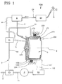
- 100 denotes a washing machine according to the present invention in its entirety and in a schematic manner.
- the machine 100 comprises, in accordance with a widely known structure, an external support frame 101 of a generally box-like shape.
- the machine 100 may comprise a containment body 102, or tub.
- This containment body 102 is usually supported by the suspension system 103 connected to the frame 101.
- This suspension system 103 may comprise vibration-damping means, for example shock absorbers and/or helical springs.
- the containment body 102 internally defines a washing compartment C1 adapted to be filled with a mixture of water and detergent during stages of operation of the machine 100.
- the containment body 102 is of a substantially cylindrical shape, and in particular it has a side wall 106 of a cylindrical shape that has an access opening at the front that is closed with a porthole "O".
- a rotary drum 104 is rotatably mounted, and set in rotation by means of a shaft 105 about a horizontal or substantially horizontal axis of rotation "X".
- the axis of rotation can in any case have any spatial orientation, for example vertical or generically inclined with respect to the horizontal.
- the drum 104 is accessible at the front from the opening provided with a porthole "O" for insertion of laundry or clothing to be washed and, as is known, it has a peripheral wall that is perforated so as to permit the mixture of water and detergent present in the washing compartment C1 to reach the laundry present in the drum 104.
- the space inside the rotary drum 104 is in fluid communication with the space external to the drum 104 and inside the containment body 102.
- at least one wall of the containment body 102, delimiting the washing compartment C1 forms an inner hollow space C2 defining an accumulation tank for water or for a mixture of water and detergent.
- the hollow space C2 is realised inside the side wall 106 and extends about the axis of rotation "X" of the drum 104.
- the hollow space C2 extends about the axis of rotation "X" of the drum 104 through an angle greater than 180°.
- the hollow space C2 is ring-shaped and completely surrounds the axis of rotation "X" of the drum 104.
- the hollow space C2 preferably extends along an extension of a complete angle about the axis "X".
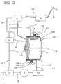
- the accumulation tank defined by the hollow space C2 is connectable to the washing compartment C1 for receiving and accumulating at least a portion of the water contained in the washing compartment C1 during an operating cycle of the washing machine 100.
- the machine 1 further comprises water hook-up means, which are active at least between the washing compartment C1 and the hollow space C2 so as to carry out a transfer of fluid at least from the washing compartment C1 to the hollow space C2.
- the water hook-up means are adapted to carry out a transfer of fluid in both directions between the washing compartment C1 and the hollow space C2. In this manner, it is possible to fill the hollow space C2 with the liquid present in the washing compartment C1, and also to drain the liquid stored in the hollow space C2 into the washing compartment C1, with recycling of the liquid.
- the water hook-up means comprise, for each of the washing compartment C1 and hollow space C2 mentioned hereinabove, a respective inlet conduit I1, I2 (arranged at an upper portion of the washing compartment C1 or hollow space C2) and a respective outlet conduit U1, U2 (arranged at a lower portion of the washing compartment C1 or hollow space C2).
- the inlet conduits I1, I2 serve for filling the washing compartment C1 and the hollow space C2, whereas the outlet conduits U1, U2 serve for emptying them.
- the hook-up means further comprise a first distributor V1, which is active on the inlet conduits I1, I2 and connected thereto for controlling the opening or closing thereof, and a second distributor V2, which is active on the outlet conduits U1, U2 for controlling the opening or closing thereof.
- the water hook-up means further comprise a connection conduit "T”, which is interposed between the two distributors V1, V2 so as to put the two distributors in fluid communication, and a third distributor V3 mounted on the connection conduit "T".
- the third distributor V3 is connectable to a drain conduit "S" and designed to selectively connect the second distributor V2 with the first distributor V1 or with a drain conduit "S".
- connection conduit "T” is thus divided into a first length T1 comprised between the second and the third distributor V2, V3, and a second length T2 comprised between the first and the third distributor V1, V3.
- connection conduit "T” On the connection conduit “T”, and preferably on the cited first length T1, there is arranged a hydraulic pump “P" designed to bring about the circulation of the liquid in the inlet, outlet and connection conduits.
- the delivery direction of the pump "P" is from the second distributor V2 towards the first distributor V1, therefore from the outlet conduits U1, U2 towards the inlet conduits I1, I2.
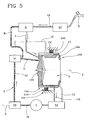
- the machine 100 further comprises a feeding circuit that is connectable to a water system so as to deliver water to the washing compartment C1.
- the feeding circuit comprises a main conduit CP that is connectable to the water system, for example by means of a tap "R" external to (not comprised in) the washing machine and, mounted on the main conduit CP, a solenoid valve EV for opening/closing the main conduit CP, a drawer “D” for mixing the water with a detergent, and a supply conduit "A" extending between the drawer and the washing compartment.
- an auxiliary conduit "W” designed to intercept at least a portion of the fluid circulating between the second distributor V2 and the inlet conduit I1 of the washing compartment C1 and to convey it towards the mixing drawer "D".
- the auxiliary conduit "W" defines a branch of the inlet conduit I1 of the washing compartment C1, as illustrated in the attached figures.
- the fluid flow rates circulating in the inlet conduit I1 and in the auxiliary conduit W are regulated by suitably dimensioning the respective sections.
- auxiliary conduit "W" directly connects the first distributor V1 with the mixing drawer "D".
- the distributors V1, V2, V3 are of the three-way or four-way type. These valves operate so as to realise a plurality of operating configurations corresponding to different operating cycles of the machine 100.
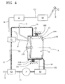
- the second distributor V2 can take on a first configuration in which it opens the outlet conduit U1 of the washing compartment C1, keeping the outlet conduit U2 of the hollow space C2 closed ( figure 2 ), a configuration in which it opens the outlet conduit U2 of the hollow space C2, keeping the outlet conduit U1 of the washing compartment C1 closed ( figure 3 ), and, preferably, also a third configuration in which it keeps both outlet conduits U1, U2 closed ( figure 1 ).
- the other two distributors V1, V3 operate in an identical manner.
- the distributors V1 and/or V2 and/or V3 can constitute distinct elements inside the water hook-up means or they can be incorporated in one or more valve assemblies.
- the distributors and/or the valve assemblies can be substituted at least in part with pumps.
- the hollow space C2 can involve any wall of the containment body 2. In particular it can involve at least a portion of the rear or front wall.
- the incorporation of the hollow space C2 in the rear wall proves to be particularly advantageous when the latter is realised with a box-like structure (for the purpose of increasing the rigidity thereof).
- inlet conduit I1 and the supply conduit A lead to the rear of the drum 104.
- the conduit I1 and/or the conduit A could lead at the front part of the drum 104, directing the jet directly inside the drum 104 with the aim of aiding in the saturation of the laundry.
- the containment body 2 is made of plastic material and comprises two reciprocally welded half-shells. Each half-shell is obtained by moulding. The moulding of the half-shell thus determines the formation of a portion of the hollow space C2.
- the method comprises the following steps:
- the method further comprises the following steps:
- the method provides for transferring into the hollow space C2 at least a portion of the rinse water utilised in the washing compartment C1 in the penultimate rinse or in a preceding rinsing cycle.
- the purpose is to avoid the transfer of the water present in the washing compartment C1 in the last rinsing cycle into the hollow space C2 (given that this water usually has fabric softener additives).
- the operations for supplying water to the washing compartment C1 and for rinsing are carried out with each cycle.
- the draining of the rinse water from the washing compartment C1 takes place with each cycle with the exception of one in which there is a transfer into the hollow space C2.
- the method comprises the following steps:
- auxiliary conduit "W” transfers to the mixing drawer “D” a portion of the wash/rinse water coming from the hollow space C2 and directed to the washing compartment C1. In any case, all of the water previously contained in the hollow space C2 can be utilised to carry out the washing of the laundry previously loaded in the drum 104.
- the amount of wash water present in the washing compartment C1 is constantly measured, for example by means of a specific level transducer (not illustrated) applied in the washing compartment C1, and additional water can be drawn from the water supply by means of activation of the solenoid valve EV (run based on a filling signal supplied by the cited transducer) in the event that the wash cycle to be carried out requires more water than the water available from the hollow space C2, as shown in Figure 5 . If instead the hollow space C2 contains excess water with respect to the amount needed for the wash cycle, the excess water can be drained according to the logic illustrated in Figure 3 .
- a level sensor (not illustrated) applied to the hollow space so as to monitor the water level therein and thus to monitor the filling thereof.
- the present invention achieves the intended aims, overcoming the above-mentioned drawbacks of the prior art.
- the peculiar structure of the machine which implements the accumulation tank directly in the containment body of the rotary drum, makes it possible to bring about an optimal action consisting of the reduction of vibrations (and thus of noise) during the spin draining step, by providing for the filling of the tank prior to that step, rendering, in any case, the machine easily transportable owing to the reduction in weight made possible by the draining of the water from the accumulation tank.
- this characteristic optimises the spaces inside the support frame of the washing machine, overcoming the necessity of having to provide special spaces for housing a separate accumulation tank and thus eliminating the critical structure-related issues existing in traditional machines. Moreover, the realisation of the latter inside the wall of the containment body of the rotary drum reduces assembly time for the machine.
- the realisation of the accumulation tank by means of a hollow space around the drum makes it possible to improve the thermal efficiency of the machine: in fact, the result of leaving the hollow space empty when the water is being heated, is that the air contained therein brings about a stage of thermal insulation that obstructs heat loss, unlike the existing solutions in which the concrete counterweights, in addition to not providing thermal insulation, act as heat absorbers to the detriment of the overall thermal efficiency of the machine.
- the present invention clearly reaches the goal of providing a laundry washing machine with an enhanced storage tank that can be manufactured with reduced assembly times.
Landscapes
- Engineering & Computer Science (AREA)
- Textile Engineering (AREA)
- Detail Structures Of Washing Machines And Dryers (AREA)
- Accessory Of Washing/Drying Machine, Commercial Washing/Drying Machine, Other Washing/Drying Machine (AREA)
- Washing And Drying Of Tableware (AREA)
Priority Applications (1)
| Application Number | Priority Date | Filing Date | Title |
|---|---|---|---|
| PL12196053T PL2607540T3 (pl) | 2011-12-22 | 2012-12-07 | Pralka ze zbiornikiem do gromadzenia wody |
Applications Claiming Priority (1)
| Application Number | Priority Date | Filing Date | Title |
|---|---|---|---|
| IT000088A ITRN20110088A1 (it) | 2011-12-22 | 2011-12-22 | Macchina lavabiancheria con serbatoio di accumulo dell'acqua. |
Publications (2)
| Publication Number | Publication Date |
|---|---|
| EP2607540A1 EP2607540A1 (en) | 2013-06-26 |
| EP2607540B1 true EP2607540B1 (en) | 2014-11-12 |
Family
ID=45814608
Family Applications (1)
| Application Number | Title | Priority Date | Filing Date |
|---|---|---|---|
| EP12196053.8A Active EP2607540B1 (en) | 2011-12-22 | 2012-12-07 | Washing machine with water storage tank |
Country Status (4)
| Country | Link |
|---|---|
| EP (1) | EP2607540B1 (pl) |
| ES (1) | ES2529995T3 (pl) |
| IT (1) | ITRN20110088A1 (pl) |
| PL (1) | PL2607540T3 (pl) |
Families Citing this family (4)
| Publication number | Priority date | Publication date | Assignee | Title |
|---|---|---|---|---|
| CN106757989B (zh) * | 2016-12-26 | 2020-04-21 | 珠海格力电器股份有限公司 | 一种洗衣机配重和洗衣机以及洗衣机的配重方法 |
| IT201900005524A1 (it) * | 2019-04-10 | 2020-10-10 | J P Ind S P A | Macchina lavatrice con sistema di contrappeso idraulico. |
| CN111979708B (zh) * | 2019-05-24 | 2023-05-30 | 青岛海尔洗涤电器有限公司 | 一种洗衣机水盒及洗衣机 |
| CN116536894A (zh) * | 2022-01-25 | 2023-08-04 | 青岛海尔洗衣机有限公司 | 一种洗衣机水循环系统及洗衣机 |
Family Cites Families (3)
| Publication number | Priority date | Publication date | Assignee | Title |
|---|---|---|---|---|
| FR2626588B1 (fr) * | 1988-01-28 | 1991-04-26 | Martinez Georges | Machine a laver le linge dont la cuve est equipee d'elements de lestage |
| IT1259200B (it) * | 1992-01-09 | 1996-03-11 | Zanussi Elettrodomestici | Lavabiancheria con procedimento perfezionato di zavorra |
| ITTO20040489A1 (it) * | 2004-07-14 | 2004-10-14 | Itw Ind Components Srl | Dispositivo per lo smorzamento di vibrazioni di un elemento di carico di un elettrodomestico, in particolare un gruppo vasca/cestello di una lavatrioce o un asciugatore. |
-
2011
- 2011-12-22 IT IT000088A patent/ITRN20110088A1/it unknown
-
2012
- 2012-12-07 PL PL12196053T patent/PL2607540T3/pl unknown
- 2012-12-07 ES ES12196053.8T patent/ES2529995T3/es active Active
- 2012-12-07 EP EP12196053.8A patent/EP2607540B1/en active Active
Also Published As
| Publication number | Publication date |
|---|---|
| ITRN20110088A1 (it) | 2013-06-23 |
| EP2607540A1 (en) | 2013-06-26 |
| ES2529995T3 (es) | 2015-02-25 |
| PL2607540T3 (pl) | 2015-05-29 |
Similar Documents
| Publication | Publication Date | Title |
|---|---|---|
| US9752267B2 (en) | Laundry treating apparatus | |
| EP2107153B1 (en) | Drum washing machine | |
| KR100716255B1 (ko) | 드럼세탁기 | |
| US8919154B2 (en) | Washing machine | |
| AU2017229296B2 (en) | Home laundry washing machine and method for controlling thereof | |
| CN101348993B (zh) | 洗衣机 | |
| EP2516718B1 (en) | Washing method and washing machine | |
| EP2607540B1 (en) | Washing machine with water storage tank | |
| US20140208810A1 (en) | Drum Washing Machine | |
| US11208753B2 (en) | Laundry machine having lower reservoir and washing processes for a laundry machine | |
| KR20150072169A (ko) | 세탁기 | |
| KR101492499B1 (ko) | 세탁기 | |
| WO2006126813A2 (en) | Steam generator and washing machine having the same | |
| CN101012616A (zh) | 一种具有独立水箱的喷淋式滚筒洗衣机 | |
| WO2014064269A1 (en) | Method for controlling a laundry washing machine and laundry washing machine | |
| EP2578739B1 (en) | Method for washing laundry in a laundry washing machine | |
| KR102013187B1 (ko) | 세탁기 및 세탁기의 세탁수 공급방법 | |
| JPH05253385A (ja) | 衣服洗濯機の安定方法の改良 | |
| GB2566475A (en) | Washing machine water circulation system | |
| JPH08229290A (ja) | ドラム式洗濯機 | |
| JP2000014985A (ja) | 補助水タンクを備えたドラム式洗濯機及びそれを用いた洗濯方法 | |
| KR20110067469A (ko) | 세탁물 처리기기 및 세탁물 처리기기의 헹굼방법 | |
| CN201012977Y (zh) | 一种具有独立水箱的喷淋式滚筒洗衣机 | |
| JP2013244384A (ja) | 洗濯機 | |
| US20050056060A1 (en) | Washing machine with improved washing-aid dispenser |
Legal Events
| Date | Code | Title | Description |
|---|---|---|---|
| 17P | Request for examination filed |
Effective date: 20130509 |
|
| AK | Designated contracting states |
Kind code of ref document: A1 Designated state(s): AL AT BE BG CH CY CZ DE DK EE ES FI FR GB GR HR HU IE IS IT LI LT LU LV MC MK MT NL NO PL PT RO RS SE SI SK SM TR |
|
| AX | Request for extension of the european patent |
Extension state: BA ME |
|
| PUAI | Public reference made under article 153(3) epc to a published international application that has entered the european phase |
Free format text: ORIGINAL CODE: 0009012 |
|
| GRAP | Despatch of communication of intention to grant a patent |
Free format text: ORIGINAL CODE: EPIDOSNIGR1 |
|
| INTG | Intention to grant announced |
Effective date: 20140620 |
|
| GRAS | Grant fee paid |
Free format text: ORIGINAL CODE: EPIDOSNIGR3 |
|
| GRAA | (expected) grant |
Free format text: ORIGINAL CODE: 0009210 |
|
| AK | Designated contracting states |
Kind code of ref document: B1 Designated state(s): AL AT BE BG CH CY CZ DE DK EE ES FI FR GB GR HR HU IE IS IT LI LT LU LV MC MK MT NL NO PL PT RO RS SE SI SK SM TR |
|
| REG | Reference to a national code |
Ref country code: GB Ref legal event code: FG4D |
|
| REG | Reference to a national code |
Ref country code: CH Ref legal event code: EP |
|
| REG | Reference to a national code |
Ref country code: AT Ref legal event code: REF Ref document number: 695856 Country of ref document: AT Kind code of ref document: T Effective date: 20141115 |
|
| REG | Reference to a national code |
Ref country code: IE Ref legal event code: FG4D |
|
| REG | Reference to a national code |
Ref country code: DE Ref legal event code: R096 Ref document number: 602012003759 Country of ref document: DE Effective date: 20141224 |
|
| REG | Reference to a national code |
Ref country code: FR Ref legal event code: PLFP Year of fee payment: 3 |
|
| REG | Reference to a national code |
Ref country code: ES Ref legal event code: FG2A Ref document number: 2529995 Country of ref document: ES Kind code of ref document: T3 Effective date: 20150225 |
|
| REG | Reference to a national code |
Ref country code: NL Ref legal event code: VDEP Effective date: 20141112 |
|
| REG | Reference to a national code |
Ref country code: AT Ref legal event code: MK05 Ref document number: 695856 Country of ref document: AT Kind code of ref document: T Effective date: 20141112 |
|
| PG25 | Lapsed in a contracting state [announced via postgrant information from national office to epo] |
Ref country code: FI Free format text: LAPSE BECAUSE OF FAILURE TO SUBMIT A TRANSLATION OF THE DESCRIPTION OR TO PAY THE FEE WITHIN THE PRESCRIBED TIME-LIMIT Effective date: 20141112 Ref country code: NO Free format text: LAPSE BECAUSE OF FAILURE TO SUBMIT A TRANSLATION OF THE DESCRIPTION OR TO PAY THE FEE WITHIN THE PRESCRIBED TIME-LIMIT Effective date: 20150212 Ref country code: PT Free format text: LAPSE BECAUSE OF FAILURE TO SUBMIT A TRANSLATION OF THE DESCRIPTION OR TO PAY THE FEE WITHIN THE PRESCRIBED TIME-LIMIT Effective date: 20150312 Ref country code: LT Free format text: LAPSE BECAUSE OF FAILURE TO SUBMIT A TRANSLATION OF THE DESCRIPTION OR TO PAY THE FEE WITHIN THE PRESCRIBED TIME-LIMIT Effective date: 20141112 Ref country code: IS Free format text: LAPSE BECAUSE OF FAILURE TO SUBMIT A TRANSLATION OF THE DESCRIPTION OR TO PAY THE FEE WITHIN THE PRESCRIBED TIME-LIMIT Effective date: 20150312 Ref country code: NL Free format text: LAPSE BECAUSE OF FAILURE TO SUBMIT A TRANSLATION OF THE DESCRIPTION OR TO PAY THE FEE WITHIN THE PRESCRIBED TIME-LIMIT Effective date: 20141112 |
|
| PG25 | Lapsed in a contracting state [announced via postgrant information from national office to epo] |
Ref country code: HR Free format text: LAPSE BECAUSE OF FAILURE TO SUBMIT A TRANSLATION OF THE DESCRIPTION OR TO PAY THE FEE WITHIN THE PRESCRIBED TIME-LIMIT Effective date: 20141112 Ref country code: GR Free format text: LAPSE BECAUSE OF FAILURE TO SUBMIT A TRANSLATION OF THE DESCRIPTION OR TO PAY THE FEE WITHIN THE PRESCRIBED TIME-LIMIT Effective date: 20150213 Ref country code: AT Free format text: LAPSE BECAUSE OF FAILURE TO SUBMIT A TRANSLATION OF THE DESCRIPTION OR TO PAY THE FEE WITHIN THE PRESCRIBED TIME-LIMIT Effective date: 20141112 Ref country code: LV Free format text: LAPSE BECAUSE OF FAILURE TO SUBMIT A TRANSLATION OF THE DESCRIPTION OR TO PAY THE FEE WITHIN THE PRESCRIBED TIME-LIMIT Effective date: 20141112 Ref country code: CY Free format text: LAPSE BECAUSE OF FAILURE TO SUBMIT A TRANSLATION OF THE DESCRIPTION OR TO PAY THE FEE WITHIN THE PRESCRIBED TIME-LIMIT Effective date: 20141112 Ref country code: RS Free format text: LAPSE BECAUSE OF FAILURE TO SUBMIT A TRANSLATION OF THE DESCRIPTION OR TO PAY THE FEE WITHIN THE PRESCRIBED TIME-LIMIT Effective date: 20141112 Ref country code: SE Free format text: LAPSE BECAUSE OF FAILURE TO SUBMIT A TRANSLATION OF THE DESCRIPTION OR TO PAY THE FEE WITHIN THE PRESCRIBED TIME-LIMIT Effective date: 20141112 |
|
| REG | Reference to a national code |
Ref country code: PL Ref legal event code: T3 |
|
| PG25 | Lapsed in a contracting state [announced via postgrant information from national office to epo] |
Ref country code: BE Free format text: LAPSE BECAUSE OF NON-PAYMENT OF DUE FEES Effective date: 20141231 |
|
| PG25 | Lapsed in a contracting state [announced via postgrant information from national office to epo] |
Ref country code: SK Free format text: LAPSE BECAUSE OF FAILURE TO SUBMIT A TRANSLATION OF THE DESCRIPTION OR TO PAY THE FEE WITHIN THE PRESCRIBED TIME-LIMIT Effective date: 20141112 Ref country code: EE Free format text: LAPSE BECAUSE OF FAILURE TO SUBMIT A TRANSLATION OF THE DESCRIPTION OR TO PAY THE FEE WITHIN THE PRESCRIBED TIME-LIMIT Effective date: 20141112 Ref country code: RO Free format text: LAPSE BECAUSE OF FAILURE TO SUBMIT A TRANSLATION OF THE DESCRIPTION OR TO PAY THE FEE WITHIN THE PRESCRIBED TIME-LIMIT Effective date: 20141112 Ref country code: DK Free format text: LAPSE BECAUSE OF FAILURE TO SUBMIT A TRANSLATION OF THE DESCRIPTION OR TO PAY THE FEE WITHIN THE PRESCRIBED TIME-LIMIT Effective date: 20141112 Ref country code: CZ Free format text: LAPSE BECAUSE OF FAILURE TO SUBMIT A TRANSLATION OF THE DESCRIPTION OR TO PAY THE FEE WITHIN THE PRESCRIBED TIME-LIMIT Effective date: 20141112 |
|
| REG | Reference to a national code |
Ref country code: DE Ref legal event code: R097 Ref document number: 602012003759 Country of ref document: DE |
|
| PG25 | Lapsed in a contracting state [announced via postgrant information from national office to epo] |
Ref country code: MC Free format text: LAPSE BECAUSE OF FAILURE TO SUBMIT A TRANSLATION OF THE DESCRIPTION OR TO PAY THE FEE WITHIN THE PRESCRIBED TIME-LIMIT Effective date: 20141112 |
|
| PLBE | No opposition filed within time limit |
Free format text: ORIGINAL CODE: 0009261 |
|
| STAA | Information on the status of an ep patent application or granted ep patent |
Free format text: STATUS: NO OPPOSITION FILED WITHIN TIME LIMIT |
|
| REG | Reference to a national code |
Ref country code: IE Ref legal event code: MM4A |
|
| 26N | No opposition filed |
Effective date: 20150813 |
|
| PG25 | Lapsed in a contracting state [announced via postgrant information from national office to epo] |
Ref country code: IE Free format text: LAPSE BECAUSE OF NON-PAYMENT OF DUE FEES Effective date: 20141207 |
|
| REG | Reference to a national code |
Ref country code: FR Ref legal event code: PLFP Year of fee payment: 4 |
|
| PG25 | Lapsed in a contracting state [announced via postgrant information from national office to epo] |
Ref country code: SI Free format text: LAPSE BECAUSE OF FAILURE TO SUBMIT A TRANSLATION OF THE DESCRIPTION OR TO PAY THE FEE WITHIN THE PRESCRIBED TIME-LIMIT Effective date: 20141112 |
|
| PG25 | Lapsed in a contracting state [announced via postgrant information from national office to epo] |
Ref country code: BG Free format text: LAPSE BECAUSE OF FAILURE TO SUBMIT A TRANSLATION OF THE DESCRIPTION OR TO PAY THE FEE WITHIN THE PRESCRIBED TIME-LIMIT Effective date: 20141112 |
|
| PG25 | Lapsed in a contracting state [announced via postgrant information from national office to epo] |
Ref country code: MT Free format text: LAPSE BECAUSE OF FAILURE TO SUBMIT A TRANSLATION OF THE DESCRIPTION OR TO PAY THE FEE WITHIN THE PRESCRIBED TIME-LIMIT Effective date: 20141112 Ref country code: LU Free format text: LAPSE BECAUSE OF NON-PAYMENT OF DUE FEES Effective date: 20141207 Ref country code: HU Free format text: LAPSE BECAUSE OF FAILURE TO SUBMIT A TRANSLATION OF THE DESCRIPTION OR TO PAY THE FEE WITHIN THE PRESCRIBED TIME-LIMIT; INVALID AB INITIO Effective date: 20121207 |
|
| REG | Reference to a national code |
Ref country code: CH Ref legal event code: PL |
|
| PG25 | Lapsed in a contracting state [announced via postgrant information from national office to epo] |
Ref country code: CH Free format text: LAPSE BECAUSE OF NON-PAYMENT OF DUE FEES Effective date: 20151231 Ref country code: LI Free format text: LAPSE BECAUSE OF NON-PAYMENT OF DUE FEES Effective date: 20151231 |
|
| REG | Reference to a national code |
Ref country code: FR Ref legal event code: PLFP Year of fee payment: 5 |
|
| PGFP | Annual fee paid to national office [announced via postgrant information from national office to epo] |
Ref country code: ES Payment date: 20161111 Year of fee payment: 5 |
|
| PG25 | Lapsed in a contracting state [announced via postgrant information from national office to epo] |
Ref country code: SM Free format text: LAPSE BECAUSE OF FAILURE TO SUBMIT A TRANSLATION OF THE DESCRIPTION OR TO PAY THE FEE WITHIN THE PRESCRIBED TIME-LIMIT Effective date: 20141112 |
|
| REG | Reference to a national code |
Ref country code: FR Ref legal event code: PLFP Year of fee payment: 6 |
|
| PGFP | Annual fee paid to national office [announced via postgrant information from national office to epo] |
Ref country code: TR Payment date: 20171127 Year of fee payment: 6 |
|
| PGFP | Annual fee paid to national office [announced via postgrant information from national office to epo] |
Ref country code: PL Payment date: 20171002 Year of fee payment: 6 |
|
| PG25 | Lapsed in a contracting state [announced via postgrant information from national office to epo] |
Ref country code: MK Free format text: LAPSE BECAUSE OF FAILURE TO SUBMIT A TRANSLATION OF THE DESCRIPTION OR TO PAY THE FEE WITHIN THE PRESCRIBED TIME-LIMIT Effective date: 20141112 |
|
| PG25 | Lapsed in a contracting state [announced via postgrant information from national office to epo] |
Ref country code: AL Free format text: LAPSE BECAUSE OF FAILURE TO SUBMIT A TRANSLATION OF THE DESCRIPTION OR TO PAY THE FEE WITHIN THE PRESCRIBED TIME-LIMIT Effective date: 20141112 |
|
| REG | Reference to a national code |
Ref country code: ES Ref legal event code: FD2A Effective date: 20190702 |
|
| PG25 | Lapsed in a contracting state [announced via postgrant information from national office to epo] |
Ref country code: ES Free format text: LAPSE BECAUSE OF NON-PAYMENT OF DUE FEES Effective date: 20171208 |
|
| PG25 | Lapsed in a contracting state [announced via postgrant information from national office to epo] |
Ref country code: PL Free format text: LAPSE BECAUSE OF NON-PAYMENT OF DUE FEES Effective date: 20181207 |
|
| PG25 | Lapsed in a contracting state [announced via postgrant information from national office to epo] |
Ref country code: TR Free format text: LAPSE BECAUSE OF NON-PAYMENT OF DUE FEES Effective date: 20181207 |
|
| P01 | Opt-out of the competence of the unified patent court (upc) registered |
Effective date: 20230522 |
|
| REG | Reference to a national code |
Ref country code: DE Ref legal event code: R081 Ref document number: 602012003759 Country of ref document: DE Owner name: WHIRLPOOL EMEA S.R.L., IT Free format text: FORMER OWNER: INDESIT COMPANY S.P.A., FABRIANO, ANCONA, IT |
|
| PGFP | Annual fee paid to national office [announced via postgrant information from national office to epo] |
Ref country code: GB Payment date: 20241217 Year of fee payment: 13 |
|
| PGFP | Annual fee paid to national office [announced via postgrant information from national office to epo] |
Ref country code: FR Payment date: 20241227 Year of fee payment: 13 |
|
| PGFP | Annual fee paid to national office [announced via postgrant information from national office to epo] |
Ref country code: IT Payment date: 20241121 Year of fee payment: 13 |
|
| PGFP | Annual fee paid to national office [announced via postgrant information from national office to epo] |
Ref country code: DE Payment date: 20241227 Year of fee payment: 13 |