EP2607535A2 - Method of operating a laundry treating appliance and appliance implementing it - Google Patents
Method of operating a laundry treating appliance and appliance implementing it Download PDFInfo
- Publication number
- EP2607535A2 EP2607535A2 EP12196818.4A EP12196818A EP2607535A2 EP 2607535 A2 EP2607535 A2 EP 2607535A2 EP 12196818 A EP12196818 A EP 12196818A EP 2607535 A2 EP2607535 A2 EP 2607535A2
- Authority
- EP
- European Patent Office
- Prior art keywords
- inertia
- drum
- speed
- determining
- plateau
- Prior art date
- Legal status (The legal status is an assumption and is not a legal conclusion. Google has not performed a legal analysis and makes no representation as to the accuracy of the status listed.)
- Granted
Links
Images


Classifications
-
- D—TEXTILES; PAPER
- D06—TREATMENT OF TEXTILES OR THE LIKE; LAUNDERING; FLEXIBLE MATERIALS NOT OTHERWISE PROVIDED FOR
- D06F—LAUNDERING, DRYING, IRONING, PRESSING OR FOLDING TEXTILE ARTICLES
- D06F35/00—Washing machines, apparatus, or methods not otherwise provided for
- D06F35/005—Methods for washing, rinsing or spin-drying
- D06F35/007—Methods for washing, rinsing or spin-drying for spin-drying only
-
- D—TEXTILES; PAPER
- D06—TREATMENT OF TEXTILES OR THE LIKE; LAUNDERING; FLEXIBLE MATERIALS NOT OTHERWISE PROVIDED FOR
- D06F—LAUNDERING, DRYING, IRONING, PRESSING OR FOLDING TEXTILE ARTICLES
- D06F33/00—Control of operations performed in washing machines or washer-dryers
- D06F33/30—Control of washing machines characterised by the purpose or target of the control
- D06F33/32—Control of operational steps, e.g. optimisation or improvement of operational steps depending on the condition of the laundry
-
- D—TEXTILES; PAPER
- D06—TREATMENT OF TEXTILES OR THE LIKE; LAUNDERING; FLEXIBLE MATERIALS NOT OTHERWISE PROVIDED FOR
- D06F—LAUNDERING, DRYING, IRONING, PRESSING OR FOLDING TEXTILE ARTICLES
- D06F2103/00—Parameters monitored or detected for the control of domestic laundry washing machines, washer-dryers or laundry dryers
- D06F2103/02—Characteristics of laundry or load
- D06F2103/04—Quantity, e.g. weight or variation of weight
-
- D—TEXTILES; PAPER
- D06—TREATMENT OF TEXTILES OR THE LIKE; LAUNDERING; FLEXIBLE MATERIALS NOT OTHERWISE PROVIDED FOR
- D06F—LAUNDERING, DRYING, IRONING, PRESSING OR FOLDING TEXTILE ARTICLES
- D06F2105/00—Systems or parameters controlled or affected by the control systems of washing machines, washer-dryers or laundry dryers
- D06F2105/46—Drum speed; Actuation of motors, e.g. starting or interrupting
- D06F2105/48—Drum speed
Definitions
- Laundry treating appliances such as a washing machine, may include a drum defining a treating chamber for receiving and treating a laundry load according to a cycle of operation.
- the cycle of operation may include a phase during which liquid may be removed from the laundry load, such as an extraction phase during which a drum holding the laundry load rotates at speeds high enough to impart a sufficient centrifugal force on the laundry load to remove the liquid.
- the extraction phase comprises one or more speed ramps, where the speed is accelerated, and a speed plateau, which is a constant speed phase.
- Most acceleration phases comprise multiple repeats of a ramp followed by a speed plateau, which increase the speed of the drum up to a final speed plateau, which represents the highest rotational speed.
- the laundry load may be satellized by centrifugal force to rotate with the drum. Extraction in this manner results in a decrease in the mass of the load as liquid is extracted during the final extraction plateau. The rate of decrease in the mass of the load slows over time as there is the amount of extractable liquid is reduced. Extraction cycles currently utilize time to determine when to terminate the final extraction plateau. On loads that are extracted quickly, remaining time, along with energy and cost, may be expended at this plateau with little or no return. For highly absorbent loads that release liquid slowly, insufficient time may be allotted, and the residual moisture content (RMC) of the load may not be as low as it should be.
- RMC residual moisture content
- a laundry treating appliance has a rotatable drum at least partially defining a treating chamber for receiving a laundry load for treatment according to at least one cycle of operation.
- a method of operating the laundry treating appliance includes extracting liquid from the laundry by rotating the drum at a speed plateau where the rotational speed of the drum is greater than a satellizing speed; monitoring the inertia of the laundry load during the speed plateau; determining a decay rate of the monitored inertia; and terminating the extracting of liquid upon the decay rate satisfying a reference value.
- FIG. 1 is a schematic, cross-sectional view of a laundry treating appliance in the form of a horizontal axis washing machine according to one embodiment of the invention.
- FIG. 2 is a schematic view of a controller of the laundry treating appliance of FIG. 1 .
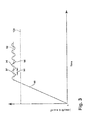
- FIG. 3 is a graphical representation of a sinusoidal torque profile superimposed on the plateau portion of the profile of the drum during a constant speed phase, with the sinusoidal profile to repeatedly determine the inertia of the laundry load during the constant speed phase in the laundry treating appliance of FIG. 1 .
- FIG. 1 is a schematic, cross-sectional view of a laundry treating appliance in the form of a horizontal axis washing machine 10 according to one embodiment of the invention.
- the laundry treating appliance is illustrated as a horizontal axis washing machine 10
- the laundry treating appliance according to the invention may be any machine that treats articles such as clothing or fabrics.
- Non-limiting examples of the laundry treating appliance may include a front loading/horizontal axis washing machine; a top loading/vertical axis washing machine; a combination washing machine and dryer; an automatic dryer; a tumbling or stationary refreshing/revitalizing machine; an extractor; a non-aqueous washing apparatus; and a revitalizing machine.
- the washing machine 10 described herein shares many features of a traditional automatic washing machine, which will not be described in detail except as necessary for a complete understanding of the invention.
- Washing machines are typically categorized as either a vertical axis washing machine or a horizontal axis washing machine.
- the "vertical axis" washing machine refers to a washing machine having a rotatable drum, perforate or imperforate, that holds fabric items and a clothes mover, such as an agitator, impeller, nutator, and the like within the drum.
- the clothes mover moves within the drum to impart mechanical energy directly to the clothes or indirectly through liquid in the drum.
- the liquid may include one of wash liquid and rinse liquid.
- the wash liquid may have at least one of water and a wash aid.
- the rinse liquid may have at least one of water and a rinse aid.
- the clothes mover may typically be moved in a reciprocating rotational movement.
- the drum rotates about a vertical axis generally perpendicular to a surface that supports the washing machine.
- the rotational axis need not be vertical.
- the drum may rotate about an axis inclined relative to the vertical axis.
- the "horizontal axis" washing machine refers to a washing machine having a rotatable drum, perforated or imperforated, that holds fabric items and washes the fabric items by rubbing against one another as the drum rotates.
- the drum rotates about a horizontal axis generally parallel to a surface that supports the washing machine.
- the rotational axis need not be horizontal.
- the drum may rotate about an axis inclined relative to the horizontal axis.
- the washing machine 10 may include a cabinet 12, which may be a frame to which decorative panels are mounted.
- a controller 14 may be provided on the cabinet 12 and controls the operation of the washing machine 10 to implement a cycle of operation.
- a user interface 16 may be included with the controller 14 to provide communication between the user and the controller 14.
- the user interface 16 may include one or more knobs, switches, displays, and the like for communicating with the user, such as to receive input and provide output.
- a rotatable drum 18 may be disposed within the interior of the cabinet 12 and defines a treating chamber 20 for treating laundry.
- the rotatable drum 18 may be mounted within an imperforate tub 22, which is suspended within the cabinet 12 by a resilient suspension system 24.
- the drum 18 may include a plurality of perforations 26, such that liquid may flow between the tub 22 and the drum 18 through the perforations 26.
- the drum 18 may further include a plurality of lifters 28 disposed on an inner surface of the drum 18 to lift a laundry load (not shown here) received in the laundry treating chamber 20 while the drum 18 rotates.
- washing machine 10 includes both the tub 22 and the drum 18, with the drum 18 defining the laundry treating chamber 20, it is within the scope of the invention for either the drum 18 or tub 22 to define the treating chamber 20 as well as the washing machine 10 including only one receptacle, with the one receptacle defining the laundry treating chamber for receiving a laundry load to be treated.
- a motor 30 is provided to rotate the drum 18.
- the motor 30 includes a stator 32 and a rotor 34, which are mounted to a drive shaft 36 extending from the drum 18 for selective rotation of the treating chamber 20 during a cycle of operation. It is also within the scope of the invention for the motor 30 to be coupled with the drive shaft 36 through a drive belt and/or a gearbox for selective rotation of the treating chamber 20.
- the motor 30 may be any suitable type of motor for rotating the drum 18.
- the motor 30 may be a brushless permanent magnet (BPM) motor having a stator 32 and a rotor 34.
- BPM brushless permanent magnet
- Other motors such as an induction motor or a permanent split capacitor (PSC) motor, may also be used.
- the motor 30 may rotate the drum 18 at various speeds in either rotational direction.
- the washing machine 10 may also include at least one balance ring 38 containing a balancing material moveable within the balance ring 38 to counterbalance an imbalance that may be caused by laundry in the treating chamber 20 during rotation of the drum 18.
- the balancing material may be in the form of metal balls, fluid or a combination thereof.
- the balance ring 38 may extend circumferentially around a periphery of the drum 18 and may be located at any desired location along an axis of rotation of the drum 18. When multiple balance rings 38 are present, they may be equally spaced along the axis of rotation of the drum 18.
- the washing machine 10 of FIG. 1 may further include a liquid supply and recirculation system.
- Liquid such as water
- a water supply 42 such as a household water supply.
- a supply conduit 44 may fluidly couple the water supply 42 to the tub 22 and a treatment dispenser 46.
- the supply conduit 44 may be provided with an inlet valve 48 for controlling the flow of liquid from the water supply 42 through the supply conduit 44 to either the tub 22 or the treatment dispenser 46.
- the dispenser 46 may be a single-use dispenser, that stores and dispenses a single dose of treating chemistry and must be refilled for each cycle of operation, or a multiple-use dispenser, also referred to as a bulk dispenser, that stores and dispenses multiple doses of treating chemistry over multiple executions of one or more cycles of operation.
- a liquid conduit 50 may fluidly couple the treatment dispenser 46 with the tub 22.
- the liquid conduit 50 may couple with the tub 22 at any suitable location on the tub 22 and is shown as being coupled to a front wall of the tub 22 in FIG. 1 for exemplary purposes.
- the liquid that flows from the treatment dispenser 46 through the liquid conduit 50 to the tub 22 typically enters a space between the tub 22 and the drum 18 and may flow by gravity to a sump 52 formed in part by a lower portion of the tub 22.
- the sump 52 may also be formed by a sump conduit 54 that may fluidly couple the lower portion of the tub 22 to a pump 56.
- the pump 56 may direct fluid to a drain conduit 58, which may drain the liquid from the washing machine 10, or to a recirculation conduit 60, which may terminate at a recirculation inlet 62.
- the recirculation inlet 62 may direct the liquid from the recirculation conduit 60 into the drum 18.
- the recirculation inlet 62 may introduce the liquid into the drum 18 in any suitable manner, such as by spraying, dripping, or providing a steady flow of the liquid.
- the liquid supply and recirculation system may further include one or more devices for heating the liquid such as a steam generator 65 and/or a sump heater 63.
- the steam generator 65 may be provided to supply steam to the treating chamber 20, either directly into the drum 18 or indirectly through the tub 22 as illustrated.
- the inlet valve 48 may also be used to control the supply of water to the steam generator 65.
- the steam generator 65 is illustrated as a flow-through steam generator, but may be other types, including a tank type steam generator.
- the heating element, in the form of the sump heater 63 may be used to heat laundry (not shown), air, the rotatable drum 18, or liquid in the tub 22 to generate steam, in place of or in addition to the steam generator 65.
- the steam generator 65 may be used to heat to the laundry as part of a cycle of operation, much in the same manner as heating element 63, as well as to introduce steam to treat the laundry.
- liquid supply and recirculation system may differ from the configuration shown in FIG. 1 , such as by inclusion of other valves, conduits, wash aid dispensers, heaters, sensors, to control the flow of treating liquid through the washing machine 10 and for the introduction of more than one type of detergent/wash aid. Further, the liquid supply and recirculation system need not include the recirculation portion of the system or may include other types of recirculation systems.
- the controller 14 may be provided in the cabinet 12 and communicably couple one or more components to receive an output signal from components and control the operation of the washing machine 10 to implement one or more cycles of operation, which is further described in detail with reference to FIG. 2 .
- the controller 14 may be provided with a memory 64 and a central processing unit (CPU) 66.
- the memory 64 may be used for storing the control software in the form of executable instructions that is executed by the CPU 66 in completing one or more cycles of operation using the washing machine 10 and any additional software. Additional software may be executed in conjunction with control software in completing a cycle of operation by the washing machine 10.
- additional software may determine at least one of the torque, inertia, and acceleration of drum 18 with laundry within the treating chamber 20, based on the input from other components and sensors 68, 70 during a cycle of operation.
- the particular program is not germane to the invention.
- the memory 64 may also be used to store information, such as a database or look-up table, or to store data received from one or more components of the washing machine 10 that may be communicably coupled with the controller 14 as needed to execute the cycle of operation.
- the controller 14 may be operably coupled with one or more components of the washing machine 10 for communicating with and controlling the operation of the component to complete a cycle of operation.
- the controller 14 may be coupled with the user interface 16 for receiving user selected inputs and communicating information with the user.
- the user interface 16 may be provided that has operational controls such as dials, lights, knobs, levers, buttons, switches, sound device, and displays enabling the user to input commands to a controller 14 and receive information about a specific cleaning cycle from sensors (not shown) in the washing machine 10 or via input by the user through the user interface 16.
- the user may enter many different types of information, including, without limitation, cycle selection and cycle parameters, such as cycle options. Any suitable cycle may be used. Non-limiting examples include, Heavy Duty, Normal, Delicates, Rinse and Spin, Sanitize, and Bio-Film Clean Out.
- the controller 14 may further be operably coupled to the motor 30 to provide a motor control signal to rotate the drum 18 according to a speed profile for the at least one cycle of operation, for controlling at least one of the direction, rotational speed, acceleration, deceleration, torque and power consumption of the motor 30.
- the controller 14 may be operably coupled to the treatment dispenser 46 for dispensing a treating chemistry during a cycle of operation.
- the controller 14 may be coupled to the steam generator 65 and the sump heater 63 to heat the liquid as required by the controller 14.
- the controller 14 may also be coupled to the pump 56 and inlet valve 48 for controlling the flow of liquid during a cycle of operation.
- the controller 14 may also receive input from one or more sensors 70, which are known in the art.
- sensors 70 include: a treating chamber temperature sensor, a moisture sensor, a weight sensor, a drum position sensor, a motor speed sensor, a motor torque sensor 68 or the like.
- the motor torque sensor 68 may include a motor controller or similar data output on the motor 30 that provides data communication with the motor 30 and outputs motor characteristic information such as oscillations, generally in the form of an analog or digital signal, to the controller 14 that is indicative of the applied torque.
- the controller 14 may use the motor characteristic information to determine the torque applied by the motor 30 using a computer program that may be stored in the controller memory 64.
- the motor torque sensor 68 may be any suitable sensor, such as a voltage or current sensor, for outputting a current or voltage signal indicative of the current or voltage supplied to the motor 30 to determine the torque applied by the motor 30.
- the motor torque sensor 68 may be a physical sensor or may be integrated with the motor 30 and combined with the capability of the controller 14, may function as a sensor.
- motor characteristics such as speed, current, voltage, direction, torque etc., may be processed such that the data provides information in the same manner as a separate physical sensor. In contemporary motors, the motors 30 often have their own controller that outputs data for such information.
- the distributed mass of the laundry load about the interior of the drum is a part of the inertia of the rotating system of the drum and laundry load, along with other rotating components of the appliance.
- the inertia of the rotating components of the appliance without the laundry is generally known and can be easily tested for.
- the inertia of the laundry load can be determined by determining the total inertia of the combined load inertia the appliance inertia, and then subtracting the known appliance inertia. In many cases, as the total inertia is proportional to the load inertia, it is not necessary to distinguish between the appliance inertia and the load inertia.
- the total inertia can be determined from the torque necessary to rotate the drum.
- C may be taken as zero since the Coulomb friction is typically very small compared to the remaining variables.
- ⁇ / ⁇ B .
- ⁇ and ⁇ are variables that may be readily determined from torque sensors and velocity sensors. The B is easily calculated during a plateau.
- the inertia was the only unknown and could be solved for.
- the acceleration was normally defined by the ramp or sensed. For example, most ramps are accomplished by providing an acceleration rate to the motor. This acceleration rate can be used for the acceleration in the equation.
- the following methodology provides for not only determining the inertia during any plateau, but doing so continuously, and doing so without the need for a ramp, either before or after the plateau.
- the methodology determines the inertia of the laundry load during a constant speed phase greater than the satellization speed.
- periodic signals are applied to the constant speed profile. It has been observed that the inertia of the laundry load may be determined by applying a periodic torque signal to the constant speed profile to split the periodic signal into two 1 ⁇ 2 wave sections to solve for the inertia of the laundry load by cancelling out damping and friction forces.
- FIG. 3 illustrates a plot of a periodic torque signal applied to the constant speed profile of the drum 18 during the constant speed phase.
- the speed profile 90 may be an extraction speed profile to remove the liquid from the laundry load in the treating chamber 20.
- the speed profile 90 may include an initial acceleration phase that may be linear, indicating a constant acceleration.
- the acceleration phase 90 may be configured to increase the rotational speed up to or exceeding a satellizing speed 100, at which most of the laundry sticks to the interior drum wall due to centrifugal force.
- the term satellizing speed refers to any speed where at least some of the laundry load satellizes, not just the speed at which satellizing is first observed to occur.
- the speed profile 90 may transition from the initial acceleration phase 90 to a speed plateau 92 in excess of the satellizing speed 100.
- a periodic torque signal 96 may be superimposed on the speed plateau 92 to determine the inertia of the laundry load during the constant speed plateau 92.
- the torque from the motor 30 may be configured to periodically increase and decrease by communicating with the motor torque sensor 68 and/or the controller 14.
- the resulting torque profile may be in the form of a periodic trace, such as the sinusoidal profile 96, or a saw tooth profile (not shown).
- the sinusoidal profile 96 may have a constant period 98, and may comprise a plurality of periods.
- the period 98 may be bisected at a maximum 94, 97 into a first half period representing a positive acceleration and a second half period representing a negative acceleration.
- the first half period may correspond to an increasing trace of the sinusoidal profile 96.
- the second half period may correspond to a decreasing trace of the sinusoidal profile 96.
- the first half period and the second half period may be symmetrical with respect to the speed plateau 92.
- Both ⁇ first and ⁇ second may be determined by the motor torque sensor 68 and/or controller 14, and the acceleration ⁇ may be a known value, such as the acceleration provided by the controller 14 to the motor 30, or may be determined by a suitable sensor. Therefore, the equation (6) may be solved for the inertia after superimposing each single period 98 of the periodic signal 96 to the speed profile 90 during the constant speed plateau 92.
- the inertia may also be updated after applying every single period 98 to the periodic signal 96.
- the inertia may be updated at a predetermined interval during an constant speed phase.
- the inertia may be updated after completion of every two, three, or other multiple periods.
- the inertia may be updated by adjusting the frequency or amplitude of the periodic torque signal 96.
- the inertia may decrease in an asymptotic manner.
- This asymptotic decay in inertia may be continuously monitored by utilizing the methodology described above until the inertia reaches a reference value representing an optimal extraction time and residual moisture content.
Abstract
Description
- Laundry treating appliances, such as a washing machine, may include a drum defining a treating chamber for receiving and treating a laundry load according to a cycle of operation. The cycle of operation may include a phase during which liquid may be removed from the laundry load, such as an extraction phase during which a drum holding the laundry load rotates at speeds high enough to impart a sufficient centrifugal force on the laundry load to remove the liquid. Typically, the extraction phase comprises one or more speed ramps, where the speed is accelerated, and a speed plateau, which is a constant speed phase. Most acceleration phases comprise multiple repeats of a ramp followed by a speed plateau, which increase the speed of the drum up to a final speed plateau, which represents the highest rotational speed.
- During the extraction phase, the laundry load may be satellized by centrifugal force to rotate with the drum. Extraction in this manner results in a decrease in the mass of the load as liquid is extracted during the final extraction plateau. The rate of decrease in the mass of the load slows over time as there is the amount of extractable liquid is reduced. Extraction cycles currently utilize time to determine when to terminate the final extraction plateau. On loads that are extracted quickly, remaining time, along with energy and cost, may be expended at this plateau with little or no return. For highly absorbent loads that release liquid slowly, insufficient time may be allotted, and the residual moisture content (RMC) of the load may not be as low as it should be.
- According to one embodiment, a laundry treating appliance has a rotatable drum at least partially defining a treating chamber for receiving a laundry load for treatment according to at least one cycle of operation. A method of operating the laundry treating appliance includes extracting liquid from the laundry by rotating the drum at a speed plateau where the rotational speed of the drum is greater than a satellizing speed; monitoring the inertia of the laundry load during the speed plateau; determining a decay rate of the monitored inertia; and terminating the extracting of liquid upon the decay rate satisfying a reference value.
- In the drawings:
-
FIG. 1 is a schematic, cross-sectional view of a laundry treating appliance in the form of a horizontal axis washing machine according to one embodiment of the invention. -
FIG. 2 is a schematic view of a controller of the laundry treating appliance ofFIG. 1 . -
FIG. 3 is a graphical representation of a sinusoidal torque profile superimposed on the plateau portion of the profile of the drum during a constant speed phase, with the sinusoidal profile to repeatedly determine the inertia of the laundry load during the constant speed phase in the laundry treating appliance ofFIG. 1 . -
FIG. 1 is a schematic, cross-sectional view of a laundry treating appliance in the form of a horizontalaxis washing machine 10 according to one embodiment of the invention. While the laundry treating appliance is illustrated as a horizontalaxis washing machine 10, the laundry treating appliance according to the invention may be any machine that treats articles such as clothing or fabrics. Non-limiting examples of the laundry treating appliance may include a front loading/horizontal axis washing machine; a top loading/vertical axis washing machine; a combination washing machine and dryer; an automatic dryer; a tumbling or stationary refreshing/revitalizing machine; an extractor; a non-aqueous washing apparatus; and a revitalizing machine. Thewashing machine 10 described herein shares many features of a traditional automatic washing machine, which will not be described in detail except as necessary for a complete understanding of the invention. - Washing machines are typically categorized as either a vertical axis washing machine or a horizontal axis washing machine. As used herein, the "vertical axis" washing machine refers to a washing machine having a rotatable drum, perforate or imperforate, that holds fabric items and a clothes mover, such as an agitator, impeller, nutator, and the like within the drum. The clothes mover moves within the drum to impart mechanical energy directly to the clothes or indirectly through liquid in the drum. The liquid may include one of wash liquid and rinse liquid. The wash liquid may have at least one of water and a wash aid. Similarly, the rinse liquid may have at least one of water and a rinse aid. The clothes mover may typically be moved in a reciprocating rotational movement. In some vertical axis washing machines, the drum rotates about a vertical axis generally perpendicular to a surface that supports the washing machine. However, the rotational axis need not be vertical. The drum may rotate about an axis inclined relative to the vertical axis. As used herein, the "horizontal axis" washing machine refers to a washing machine having a rotatable drum, perforated or imperforated, that holds fabric items and washes the fabric items by rubbing against one another as the drum rotates. In some horizontal axis washing machines, the drum rotates about a horizontal axis generally parallel to a surface that supports the washing machine. However, the rotational axis need not be horizontal. The drum may rotate about an axis inclined relative to the horizontal axis. In horizontal axis washing machines, the clothes are lifted by the rotating drum and then fall in response to gravity to form a tumbling action. Mechanical energy is imparted to the clothes by the tumbling action formed by the repeated lifting and dropping of the clothes. Vertical axis and horizontal axis machines are best differentiated by the manner in which they impart mechanical energy to the fabric items. The illustrated exemplary washing machine of
FIG. 1 is a horizontal axis washing machine. - The
washing machine 10 may include acabinet 12, which may be a frame to which decorative panels are mounted. Acontroller 14 may be provided on thecabinet 12 and controls the operation of thewashing machine 10 to implement a cycle of operation. Auser interface 16 may be included with thecontroller 14 to provide communication between the user and thecontroller 14. Theuser interface 16 may include one or more knobs, switches, displays, and the like for communicating with the user, such as to receive input and provide output. - A
rotatable drum 18 may be disposed within the interior of thecabinet 12 and defines a treatingchamber 20 for treating laundry. Therotatable drum 18 may be mounted within animperforate tub 22, which is suspended within thecabinet 12 by aresilient suspension system 24. Thedrum 18 may include a plurality ofperforations 26, such that liquid may flow between thetub 22 and thedrum 18 through theperforations 26. Thedrum 18 may further include a plurality oflifters 28 disposed on an inner surface of thedrum 18 to lift a laundry load (not shown here) received in thelaundry treating chamber 20 while thedrum 18 rotates. - While the illustrated
washing machine 10 includes both thetub 22 and thedrum 18, with thedrum 18 defining thelaundry treating chamber 20, it is within the scope of the invention for either thedrum 18 ortub 22 to define the treatingchamber 20 as well as thewashing machine 10 including only one receptacle, with the one receptacle defining the laundry treating chamber for receiving a laundry load to be treated. - A
motor 30 is provided to rotate thedrum 18. Themotor 30 includes astator 32 and arotor 34, which are mounted to adrive shaft 36 extending from thedrum 18 for selective rotation of the treatingchamber 20 during a cycle of operation. It is also within the scope of the invention for themotor 30 to be coupled with thedrive shaft 36 through a drive belt and/or a gearbox for selective rotation of the treatingchamber 20. - The
motor 30 may be any suitable type of motor for rotating thedrum 18. In one example, themotor 30 may be a brushless permanent magnet (BPM) motor having astator 32 and arotor 34. Other motors, such as an induction motor or a permanent split capacitor (PSC) motor, may also be used. Themotor 30 may rotate thedrum 18 at various speeds in either rotational direction. - The
washing machine 10 may also include at least onebalance ring 38 containing a balancing material moveable within thebalance ring 38 to counterbalance an imbalance that may be caused by laundry in the treatingchamber 20 during rotation of thedrum 18. The balancing material may be in the form of metal balls, fluid or a combination thereof. Thebalance ring 38 may extend circumferentially around a periphery of thedrum 18 and may be located at any desired location along an axis of rotation of thedrum 18. Whenmultiple balance rings 38 are present, they may be equally spaced along the axis of rotation of thedrum 18. - The
washing machine 10 ofFIG. 1 may further include a liquid supply and recirculation system. Liquid, such as water, may be supplied to thewashing machine 10 from awater supply 42, such as a household water supply. Asupply conduit 44 may fluidly couple thewater supply 42 to thetub 22 and atreatment dispenser 46. Thesupply conduit 44 may be provided with aninlet valve 48 for controlling the flow of liquid from thewater supply 42 through thesupply conduit 44 to either thetub 22 or thetreatment dispenser 46. Thedispenser 46 may be a single-use dispenser, that stores and dispenses a single dose of treating chemistry and must be refilled for each cycle of operation, or a multiple-use dispenser, also referred to as a bulk dispenser, that stores and dispenses multiple doses of treating chemistry over multiple executions of one or more cycles of operation. - A
liquid conduit 50 may fluidly couple thetreatment dispenser 46 with thetub 22. Theliquid conduit 50 may couple with thetub 22 at any suitable location on thetub 22 and is shown as being coupled to a front wall of thetub 22 inFIG. 1 for exemplary purposes. The liquid that flows from thetreatment dispenser 46 through theliquid conduit 50 to thetub 22 typically enters a space between thetub 22 and thedrum 18 and may flow by gravity to asump 52 formed in part by a lower portion of thetub 22. Thesump 52 may also be formed by asump conduit 54 that may fluidly couple the lower portion of thetub 22 to apump 56. Thepump 56 may direct fluid to adrain conduit 58, which may drain the liquid from thewashing machine 10, or to arecirculation conduit 60, which may terminate at arecirculation inlet 62. Therecirculation inlet 62 may direct the liquid from therecirculation conduit 60 into thedrum 18. Therecirculation inlet 62 may introduce the liquid into thedrum 18 in any suitable manner, such as by spraying, dripping, or providing a steady flow of the liquid. - The liquid supply and recirculation system may further include one or more devices for heating the liquid such as a
steam generator 65 and/or asump heater 63. Thesteam generator 65 may be provided to supply steam to the treatingchamber 20, either directly into thedrum 18 or indirectly through thetub 22 as illustrated. Theinlet valve 48 may also be used to control the supply of water to thesteam generator 65. Thesteam generator 65 is illustrated as a flow-through steam generator, but may be other types, including a tank type steam generator. Alternatively, the heating element, in the form of thesump heater 63, may be used to heat laundry (not shown), air, therotatable drum 18, or liquid in thetub 22 to generate steam, in place of or in addition to thesteam generator 65. Thesteam generator 65 may be used to heat to the laundry as part of a cycle of operation, much in the same manner asheating element 63, as well as to introduce steam to treat the laundry. - Additionally, the liquid supply and recirculation system may differ from the configuration shown in
FIG. 1 , such as by inclusion of other valves, conduits, wash aid dispensers, heaters, sensors, to control the flow of treating liquid through thewashing machine 10 and for the introduction of more than one type of detergent/wash aid. Further, the liquid supply and recirculation system need not include the recirculation portion of the system or may include other types of recirculation systems. - The
controller 14 may be provided in thecabinet 12 and communicably couple one or more components to receive an output signal from components and control the operation of thewashing machine 10 to implement one or more cycles of operation, which is further described in detail with reference toFIG. 2 . Thecontroller 14 may be provided with amemory 64 and a central processing unit (CPU) 66. Thememory 64 may be used for storing the control software in the form of executable instructions that is executed by theCPU 66 in completing one or more cycles of operation using thewashing machine 10 and any additional software. Additional software may be executed in conjunction with control software in completing a cycle of operation by thewashing machine 10. For example, additional software may determine at least one of the torque, inertia, and acceleration ofdrum 18 with laundry within the treatingchamber 20, based on the input from other components andsensors - The
memory 64 may also be used to store information, such as a database or look-up table, or to store data received from one or more components of thewashing machine 10 that may be communicably coupled with thecontroller 14 as needed to execute the cycle of operation. - The
controller 14 may be operably coupled with one or more components of thewashing machine 10 for communicating with and controlling the operation of the component to complete a cycle of operation. For example, thecontroller 14 may be coupled with theuser interface 16 for receiving user selected inputs and communicating information with the user. Theuser interface 16 may be provided that has operational controls such as dials, lights, knobs, levers, buttons, switches, sound device, and displays enabling the user to input commands to acontroller 14 and receive information about a specific cleaning cycle from sensors (not shown) in thewashing machine 10 or via input by the user through theuser interface 16. - The user may enter many different types of information, including, without limitation, cycle selection and cycle parameters, such as cycle options. Any suitable cycle may be used. Non-limiting examples include, Heavy Duty, Normal, Delicates, Rinse and Spin, Sanitize, and Bio-Film Clean Out.
- The
controller 14 may further be operably coupled to themotor 30 to provide a motor control signal to rotate thedrum 18 according to a speed profile for the at least one cycle of operation, for controlling at least one of the direction, rotational speed, acceleration, deceleration, torque and power consumption of themotor 30. - The
controller 14 may be operably coupled to thetreatment dispenser 46 for dispensing a treating chemistry during a cycle of operation. Thecontroller 14 may be coupled to thesteam generator 65 and thesump heater 63 to heat the liquid as required by thecontroller 14. Thecontroller 14 may also be coupled to thepump 56 andinlet valve 48 for controlling the flow of liquid during a cycle of operation. - The
controller 14 may also receive input from one ormore sensors 70, which are known in the art. Non-limiting examples of sensors that may be communicably coupled with thecontroller 14 include: a treating chamber temperature sensor, a moisture sensor, a weight sensor, a drum position sensor, a motor speed sensor, amotor torque sensor 68 or the like. - The
motor torque sensor 68 may include a motor controller or similar data output on themotor 30 that provides data communication with themotor 30 and outputs motor characteristic information such as oscillations, generally in the form of an analog or digital signal, to thecontroller 14 that is indicative of the applied torque. Thecontroller 14 may use the motor characteristic information to determine the torque applied by themotor 30 using a computer program that may be stored in thecontroller memory 64. Specifically, themotor torque sensor 68 may be any suitable sensor, such as a voltage or current sensor, for outputting a current or voltage signal indicative of the current or voltage supplied to themotor 30 to determine the torque applied by themotor 30. Additionally, themotor torque sensor 68 may be a physical sensor or may be integrated with themotor 30 and combined with the capability of thecontroller 14, may function as a sensor. For example, motor characteristics, such as speed, current, voltage, direction, torque etc., may be processed such that the data provides information in the same manner as a separate physical sensor. In contemporary motors, themotors 30 often have their own controller that outputs data for such information. - When the
drum 18 with the laundry load rotates during an extraction phase, the distributed mass of the laundry load about the interior of the drum is a part of the inertia of the rotating system of the drum and laundry load, along with other rotating components of the appliance. The inertia of the rotating components of the appliance without the laundry is generally known and can be easily tested for. Thus, the inertia of the laundry load can be determined by determining the total inertia of the combined load inertia the appliance inertia, and then subtracting the known appliance inertia. In many cases, as the total inertia is proportional to the load inertia, it is not necessary to distinguish between the appliance inertia and the load inertia. - The total inertia can be determined from the torque necessary to rotate the drum. Generally the motor torque for rotating the
drum 18 with the laundry load may be represented in the following way:
where, τ = torque, J = inertia, ω̇ = acceleration, ω = rotational speed, B = viscous damping coefficient, and C = coulomb friction. - Historically, to determine the inertia, it was necessary to have a plateau followed by a ramp. During the plateau, the rotational speed may be maintained to be constant, and the resulting acceleration (ω̇) may be zero. Then, from equation (1), the torque may be expressed only in terms of B * ω in the following way:

- C may be taken as zero since the Coulomb friction is typically very small compared to the remaining variables. Rearranging the variables, we have:

τ and ω are variables that may be readily determined from torque sensors and velocity sensors. The B is easily calculated during a plateau. - Once B was known, it was possible to determine the inertia by accelerating the drum along a ramp. During such an acceleration, the inertia was the only unknown and could be solved for. The acceleration was normally defined by the ramp or sensed. For example, most ramps are accomplished by providing an acceleration rate to the motor. This acceleration rate can be used for the acceleration in the equation.
- One shortcoming of this approach is that B tends to be a function of speed and may increase as speed increases. The B calculated on the plateau was not the same value of B where the inertia was calculated. This error was generally minimal compared to the magnitude of the other numbers and could often be ignored. To minimize the error, the inertia could be calculated along the ramp as close as possible to the plateau.
- Another, and for the current purposes, a more important shortcoming is that the prior method required a plateau followed by a ramp to calculate the inertia, which made it practically impossible to calculate the inertia during the final extraction plateau because there was no subsequent ramp.
- The following methodology provides for not only determining the inertia during any plateau, but doing so continuously, and doing so without the need for a ramp, either before or after the plateau. The methodology determines the inertia of the laundry load during a constant speed phase greater than the satellization speed. During the constant speed phase, periodic signals are applied to the constant speed profile. It has been observed that the inertia of the laundry load may be determined by applying a periodic torque signal to the constant speed profile to split the periodic signal into two ½ wave sections to solve for the inertia of the laundry load by cancelling out damping and friction forces.
-
FIG. 3 illustrates a plot of a periodic torque signal applied to the constant speed profile of thedrum 18 during the constant speed phase. Thespeed profile 90 may be an extraction speed profile to remove the liquid from the laundry load in the treatingchamber 20. Thespeed profile 90 may include an initial acceleration phase that may be linear, indicating a constant acceleration. Theacceleration phase 90 may be configured to increase the rotational speed up to or exceeding asatellizing speed 100, at which most of the laundry sticks to the interior drum wall due to centrifugal force. As used herein, the term satellizing speed refers to any speed where at least some of the laundry load satellizes, not just the speed at which satellizing is first observed to occur. - The
speed profile 90 may transition from theinitial acceleration phase 90 to aspeed plateau 92 in excess of thesatellizing speed 100. Aperiodic torque signal 96 may be superimposed on thespeed plateau 92 to determine the inertia of the laundry load during theconstant speed plateau 92. For example, the torque from themotor 30 may be configured to periodically increase and decrease by communicating with themotor torque sensor 68 and/or thecontroller 14. As a result, the resulting torque profile may be in the form of a periodic trace, such as thesinusoidal profile 96, or a saw tooth profile (not shown). Thesinusoidal profile 96 may have aconstant period 98, and may comprise a plurality of periods. Theperiod 98 may be bisected at a maximum 94, 97 into a first half period representing a positive acceleration and a second half period representing a negative acceleration. The first half period may correspond to an increasing trace of thesinusoidal profile 96. The second half period may correspond to a decreasing trace of thesinusoidal profile 96. The first half period and the second half period may be symmetrical with respect to thespeed plateau 92. - The torque may be determined individually for the first and second half periods. For example, utilizing the relationship expressed in equation (1), the torque for the first half period and the second half period may be determined in the following manner:


- The difference between the torque of the
motor 30 for a first half period and the torque of themotor 30 for the second half period may be represented in the following equation:
- Equation (5) may be solved for inertia, J, so that:

- Both τ first and τ second may be determined by the
motor torque sensor 68 and/orcontroller 14, and the acceleration ω̇ may be a known value, such as the acceleration provided by thecontroller 14 to themotor 30, or may be determined by a suitable sensor. Therefore, the equation (6) may be solved for the inertia after superimposing eachsingle period 98 of theperiodic signal 96 to thespeed profile 90 during theconstant speed plateau 92. - The inertia may also be updated after applying every
single period 98 to theperiodic signal 96. Alternatively, the inertia may be updated at a predetermined interval during an constant speed phase. For example, the inertia may be updated after completion of every two, three, or other multiple periods. The inertia may be updated by adjusting the frequency or amplitude of theperiodic torque signal 96. - As the extraction progresses, the inertia may decrease in an asymptotic manner. This asymptotic decay in inertia may be continuously monitored by utilizing the methodology described above until the inertia reaches a reference value representing an optimal extraction time and residual moisture content.
Claims (15)
- A method of operating a laundry treating appliance (10) having a rotatable drum (18) at least partially defining a treating chamber (20) for receiving a laundry load for treatment according to at least one cycle of operation, the method comprising:extracting liquid from the laundry by rotating the drum (18) at a speed plateau (92) where the rotational speed of the drum is greater than a satellizing speed (100);monitoring the inertia of the laundry load during the speed plateau(92);determining a decay rate of the monitored inertia; andterminating the extracting of liquid upon the decay rate satisfying a reference value.
- The method of claim 1 wherein the rotating the drum (18) at a speed plateau (92) comprises rotating the drum at multiple speed plateaus.
- The method of claim 2 wherein at least one of the multiple speed plateaus (92) comprises a maximum speed plateau and the determining the decay rate comprises determining the decay rate for the maximum speed plateau.
- The method of claim 1 wherein the monitoring the inertia comprises repeatedly determining the inertia during the speed plateau (92).
- The method of claim 4 wherein the repeatedly determining the inertia comprises repeatedly oscillating the rotational speed of the drum (18) about the speed plateau (92) and determining the inertia from the oscillations.
- The method of claim 5 wherein the determining the inertia from the oscillations comprises determining the inertia from the variation of a torque signal of a motor (30) rotatably driving the drum (18) during the oscillations.
- The method of claim 1 wherein the satisfying a reference value comprises the decay rate satisfying a threshold.
- The method of claim 7 wherein the satisfying a threshold comprises the decay rate falling below a threshold.
- The method of claim 1 wherein the speed plateau (92) comprises a maximum speed plateau and the determining the decay rate comprises determining the decay rate for the maximum speed plateau, wherein the monitoring the inertia comprises repeatedly determining the inertia by repeatedly oscillating the rotational speed of the drum (18) about the speed plateau (92) and determining the inertia from the oscillations.
- The method of claim 1 wherein the monitoring the inertia comprises monitoring an operating parameter indicative of the inertia of the load.
- The method of claim 10 wherein the operating parameter comprises the combined inertia of the drum and the laundry load.
- A laundry treating appliance (10) for treating a laundry load according to at least one cycle of operation, comprising:a rotatable drum (18) at least partially defining a treating chamber (20) for receiving the laundry load;a motor (30) rotatably driving the drum (18) in response to a speed control signal; anda controller (14) operably coupled to the motor (30) and providing a speed control signal to the motor to rotate the drum (18) at a maximum speed plateau (92) to effect an extracting of liquid from the laundry load, repeatedly determining the inertia of the laundry load during the maximum speed plateau by oscillating the rotational speed of the drum (18) about the maximum speed plateau and determining the inertia from the oscillations, determining a change in the inertia from the repeated determinations of inertia, and terminating the maximum speed plateau upon the change in inertia satisfying a reference value.
- The laundry treating appliance of claim 12 further comprising a torque sensor (68) outputting a torque signal indicative of the torque of the motor (30), with the controller (14) receiving the torque signal and using the variations in the torque signal resulting from the oscillations to determine the inertia.
- The laundry treating appliance of claim 12 wherein the speed control signal comprises a periodic component, in addition to constant speed component, to effect the oscillations.
- The laundry treating appliance of claim 14 wherein the periodic component is a sine wave (96).
Priority Applications (1)
| Application Number | Priority Date | Filing Date | Title |
|---|---|---|---|
| PL12196818T PL2607535T3 (en) | 2011-12-20 | 2012-12-12 | Method of operating a laundry treating appliance |
Applications Claiming Priority (2)
| Application Number | Priority Date | Filing Date | Title |
|---|---|---|---|
| US201161577838P | 2011-12-20 | 2011-12-20 | |
| US13/469,116 US9091011B2 (en) | 2011-12-20 | 2012-05-11 | Continuous high speed inertia detection |
Publications (3)
| Publication Number | Publication Date |
|---|---|
| EP2607535A2 true EP2607535A2 (en) | 2013-06-26 |
| EP2607535A3 EP2607535A3 (en) | 2015-11-11 |
| EP2607535B1 EP2607535B1 (en) | 2017-02-01 |
Family
ID=47519839
Family Applications (1)
| Application Number | Title | Priority Date | Filing Date |
|---|---|---|---|
| EP12196818.4A Not-in-force EP2607535B1 (en) | 2011-12-20 | 2012-12-12 | Method of operating a laundry treating appliance |
Country Status (3)
| Country | Link |
|---|---|
| US (2) | US9091011B2 (en) |
| EP (1) | EP2607535B1 (en) |
| PL (1) | PL2607535T3 (en) |
Cited By (1)
| Publication number | Priority date | Publication date | Assignee | Title |
|---|---|---|---|---|
| EP3875661A1 (en) * | 2020-03-02 | 2021-09-08 | Haier Deutschland GmbH | Method to estimate a load behavior in a laundry treatment machine |
Families Citing this family (13)
| Publication number | Priority date | Publication date | Assignee | Title |
|---|---|---|---|---|
| US9540756B2 (en) | 2013-10-11 | 2017-01-10 | Whirlpool Corporation | Laundry treating appliance and method of filling a laundry treating appliance with liquid |
| JP6437188B2 (en) * | 2013-11-06 | 2018-12-12 | 三星電子株式会社Samsung Electronics Co.,Ltd. | Washing machine |
| US9988751B2 (en) | 2015-07-29 | 2018-06-05 | Whirlpool Corporation | Laundry treating appliance and methods of reducing tub contact therein |
| US10273621B2 (en) | 2015-10-01 | 2019-04-30 | Whirlpool Corporation | Laundry treating appliance and methods of operation |
| US10041202B2 (en) | 2015-11-19 | 2018-08-07 | Whirlpool Corporation | Laundry treating appliance and methods of operation |
| US9885135B2 (en) | 2015-11-19 | 2018-02-06 | Whirlpool Corporation | Laundry treating appliance and methods of operation |
| US9890490B2 (en) | 2015-11-19 | 2018-02-13 | Whirlpool Corporation | Laundry treating appliance and methods of operation |
| US9988753B2 (en) | 2015-11-19 | 2018-06-05 | Whirlpool Corporation | Laundry treating appliance and methods of operation |
| US9863080B2 (en) | 2015-11-19 | 2018-01-09 | Whirlpool Corporation | Laundry treating appliance and methods of operation |
| US9873968B2 (en) | 2015-11-19 | 2018-01-23 | Whirlpool Corporation | Laundry treating appliance and methods of operation |
| US10570543B2 (en) * | 2016-10-06 | 2020-02-25 | Emz-Hanauer Gmbh & Co. Kgaa | Washing machine and method of controlling the washing machine |
| DE102019205240A1 (en) * | 2019-04-11 | 2020-10-15 | BSH Hausgeräte GmbH | Laundry care device with one control |
| US11427950B2 (en) | 2019-08-22 | 2022-08-30 | Whirlpool Corporation | Method of determining volume of water to add to first and second washing compartments of a washing machine as a function of determined moment of inertia |
Family Cites Families (25)
| Publication number | Priority date | Publication date | Assignee | Title |
|---|---|---|---|---|
| FR2553881B1 (en) | 1983-10-25 | 1987-11-20 | Esswein Sa | METHOD FOR DETERMINING A LAUNDRY LOAD IN A ROTATING DRUM, AND WASHING AND / OR DRYING MACHINE USING THE SAME |
| US4679414A (en) | 1985-01-18 | 1987-07-14 | Sharp Kabushiki Kaisha | Apparatus for controlling a dewatering process |
| US4782544A (en) | 1987-04-16 | 1988-11-08 | Whirlpool Corporation | Water extraction method and control for automatic washer |
| FR2650844B1 (en) | 1989-07-28 | 1991-10-11 | Ciapem | WASHING MACHINE OR DRYER IN WHICH THE LOAD OF LAUNDRY IS DETERMINED AUTOMATICALLY |
| JP3226592B2 (en) | 1992-03-31 | 2001-11-05 | 株式会社東芝 | Washing machine |
| DE4336349A1 (en) | 1993-10-25 | 1995-04-27 | Bosch Siemens Hausgeraete | Method for determining the mass of wet laundry in a laundry drum |
| US5585704A (en) | 1994-01-28 | 1996-12-17 | Elzind; Adel H. | Computer means for commercial washing machines |
| JPH09225199A (en) | 1996-02-26 | 1997-09-02 | Sanyo Electric Co Ltd | Clothes dryer |
| DE19928657A1 (en) | 1999-06-23 | 2000-12-28 | Diehl Ako Stiftung Gmbh & Co | Process is for measuring load of motor-driven drum of washing machine or dryer |
| US6418581B1 (en) * | 1999-06-24 | 2002-07-16 | Ipso-Usa, Inc. | Control system for measuring load imbalance and optimizing spin speed in a laundry washing machine |
| US6640372B2 (en) * | 2000-06-26 | 2003-11-04 | Whirlpool Corporation | Method and apparatus for detecting load unbalance in an appliance |
| ITMI20010799A1 (en) | 2001-04-12 | 2002-10-12 | Whirlpool Co | METHOD FOR OBTAINING EXTERNAL STRUCTURAL PARTS OF A HOUSEHOLD APPLIANCE WITHOUT SURFACE DEFECTS |
| KR100934652B1 (en) * | 2002-12-28 | 2009-12-31 | 엘지전자 주식회사 | Washing machine control method |
| JP2004242430A (en) | 2003-02-06 | 2004-08-26 | Toshiba Corp | Vector control inverter arrangement and washing machine |
| BR0300737A (en) | 2003-03-13 | 2004-11-16 | Multibras Eletrodomesticos Sa | Automatic washing machine load detection system and process |
| US7591038B2 (en) | 2003-04-28 | 2009-09-22 | Emerson Electric Co., | Method and system for operating a clothes washing machine |
| US7739764B2 (en) * | 2005-04-27 | 2010-06-22 | Whirlpool Corporation | Method and apparatus for monitoring load size and load imbalance in washing machine |
| KR100701959B1 (en) | 2005-05-11 | 2007-03-30 | 엘지전자 주식회사 | Control method of washing machine with dryer |
| JP2006346324A (en) * | 2005-06-20 | 2006-12-28 | Hitachi Appliances Inc | Washing machine |
| KR100788974B1 (en) * | 2005-08-19 | 2007-12-27 | 엘지전자 주식회사 | Method for sensing vibration of washing machine |
| US20070151041A1 (en) * | 2005-12-30 | 2007-07-05 | Mcallister Karl D | Control process for a revitalizing appliance |
| DE102006032337A1 (en) * | 2006-07-12 | 2008-01-17 | BSH Bosch und Siemens Hausgeräte GmbH | Method for controlling a spin cycle of a washing machine and suitable for performing the method suitable washing machine |
| JP4656660B2 (en) | 2006-10-20 | 2011-03-23 | パナソニック株式会社 | Washing machine |
| US20090106913A1 (en) | 2007-10-30 | 2009-04-30 | Suel Ii Richard D | Measuring apparatus and method |
| JP5042808B2 (en) * | 2007-12-27 | 2012-10-03 | 三星電子株式会社 | Drum washing machine |
-
2012
- 2012-05-11 US US13/469,116 patent/US9091011B2/en not_active Expired - Fee Related
- 2012-12-12 EP EP12196818.4A patent/EP2607535B1/en not_active Not-in-force
- 2012-12-12 PL PL12196818T patent/PL2607535T3/en unknown
-
2015
- 2015-07-09 US US14/795,076 patent/US9890489B2/en not_active Expired - Fee Related
Non-Patent Citations (1)
| Title |
|---|
| None |
Cited By (2)
| Publication number | Priority date | Publication date | Assignee | Title |
|---|---|---|---|---|
| EP3875661A1 (en) * | 2020-03-02 | 2021-09-08 | Haier Deutschland GmbH | Method to estimate a load behavior in a laundry treatment machine |
| EP4036300A1 (en) * | 2020-03-02 | 2022-08-03 | HAIER Germany GmbH | Method to estimate a load behavior in a laundry treatment machine |
Also Published As
| Publication number | Publication date |
|---|---|
| EP2607535B1 (en) | 2017-02-01 |
| US20130152311A1 (en) | 2013-06-20 |
| US9890489B2 (en) | 2018-02-13 |
| US9091011B2 (en) | 2015-07-28 |
| EP2607535A3 (en) | 2015-11-11 |
| PL2607535T3 (en) | 2017-05-31 |
| US20150315735A1 (en) | 2015-11-05 |
Similar Documents
| Publication | Publication Date | Title |
|---|---|---|
| US9890489B2 (en) | Laundry treating appliance and method using inertia detection to control liquid extraction | |
| US9938653B2 (en) | Apparatus and method for determining inertia of a laundry load | |
| EP2607543B1 (en) | Method for determining an inertia of a laundry load in a laundry treating appliance | |
| US8186227B2 (en) | Method and apparatus for determining load amount in a laundry treating appliance | |
| EP2684990B1 (en) | Laundry treating appliance and method of operation | |
| US9157177B2 (en) | Laundry treating appliance and method of control | |
| EP2463431B1 (en) | Method and apparatus for controlling the extraction duration in a laundry treating appliance | |
| EP2607536A1 (en) | Efficient energy usage for a laundry appliance | |
| US9551103B2 (en) | Method to detect the type of a load in a laundry treating appliance | |
| EP2463433A2 (en) | Method and apparatus for redistributing an imbalance in a laundry treating appliance | |
| EP2821538A1 (en) | Method of operation for a laundry treating appliance with a ball balance ring | |
| US20130047344A1 (en) | Method and apparatus for preventing an imbalance in a laundry treating appliance | |
| EP2377982B1 (en) | Method of determining an unbalance condition in a laundry appliance and laundry treating appliance | |
| US20130000054A1 (en) | Method of operating a laundry treating appliance to detect contact between a drum and tub | |
| EP2524989B1 (en) | Method and apparatus for determining load fall in a laundry trating appliance | |
| US9890492B2 (en) | Method of determining inertia in a laundry treating appliance | |
| EP2684991B1 (en) | Method of operation of a laundry treating appliance | |
| US10501880B2 (en) | Laundry treating appliance and method of operation | |
| BR102012032561A2 (en) | HIGH SPEED INERCIA DETECTION |
Legal Events
| Date | Code | Title | Description |
|---|---|---|---|
| AK | Designated contracting states |
Kind code of ref document: A2 Designated state(s): AL AT BE BG CH CY CZ DE DK EE ES FI FR GB GR HR HU IE IS IT LI LT LU LV MC MK MT NL NO PL PT RO RS SE SI SK SM TR |
|
| AX | Request for extension of the european patent |
Extension state: BA ME |
|
| PUAI | Public reference made under article 153(3) epc to a published international application that has entered the european phase |
Free format text: ORIGINAL CODE: 0009012 |
|
| PUAL | Search report despatched |
Free format text: ORIGINAL CODE: 0009013 |
|
| AK | Designated contracting states |
Kind code of ref document: A3 Designated state(s): AL AT BE BG CH CY CZ DE DK EE ES FI FR GB GR HR HU IE IS IT LI LT LU LV MC MK MT NL NO PL PT RO RS SE SI SK SM TR |
|
| AX | Request for extension of the european patent |
Extension state: BA ME |
|
| RIC1 | Information provided on ipc code assigned before grant |
Ipc: D06F 33/02 20060101AFI20151002BHEP Ipc: D06F 35/00 20060101ALI20151002BHEP |
|
| 17P | Request for examination filed |
Effective date: 20160511 |
|
| RBV | Designated contracting states (corrected) |
Designated state(s): AL AT BE BG CH CY CZ DE DK EE ES FI FR GB GR HR HU IE IS IT LI LT LU LV MC MK MT NL NO PL PT RO RS SE SI SK SM TR |
|
| GRAP | Despatch of communication of intention to grant a patent |
Free format text: ORIGINAL CODE: EPIDOSNIGR1 |
|
| INTG | Intention to grant announced |
Effective date: 20160907 |
|
| GRAJ | Information related to disapproval of communication of intention to grant by the applicant or resumption of examination proceedings by the epo deleted |
Free format text: ORIGINAL CODE: EPIDOSDIGR1 |
|
| GRAS | Grant fee paid |
Free format text: ORIGINAL CODE: EPIDOSNIGR3 |
|
| STAA | Information on the status of an ep patent application or granted ep patent |
Free format text: STATUS: GRANT OF PATENT IS INTENDED |
|
| INTC | Intention to grant announced (deleted) | ||
| GRAP | Despatch of communication of intention to grant a patent |
Free format text: ORIGINAL CODE: EPIDOSNIGR1 |
|
| INTG | Intention to grant announced |
Effective date: 20161125 |
|
| GRAA | (expected) grant |
Free format text: ORIGINAL CODE: 0009210 |
|
| STAA | Information on the status of an ep patent application or granted ep patent |
Free format text: STATUS: THE PATENT HAS BEEN GRANTED |
|
| AK | Designated contracting states |
Kind code of ref document: B1 Designated state(s): AL AT BE BG CH CY CZ DE DK EE ES FI FR GB GR HR HU IE IS IT LI LT LU LV MC MK MT NL NO PL PT RO RS SE SI SK SM TR |
|
| REG | Reference to a national code |
Ref country code: GB Ref legal event code: FG4D |
|
| REG | Reference to a national code |
Ref country code: CH Ref legal event code: EP Ref country code: AT Ref legal event code: REF Ref document number: 865697 Country of ref document: AT Kind code of ref document: T Effective date: 20170215 |
|
| REG | Reference to a national code |
Ref country code: IE Ref legal event code: FG4D |
|
| REG | Reference to a national code |
Ref country code: DE Ref legal event code: R096 Ref document number: 602012028214 Country of ref document: DE |
|
| REG | Reference to a national code |
Ref country code: NL Ref legal event code: MP Effective date: 20170201 |
|
| REG | Reference to a national code |
Ref country code: LT Ref legal event code: MG4D |
|
| REG | Reference to a national code |
Ref country code: AT Ref legal event code: MK05 Ref document number: 865697 Country of ref document: AT Kind code of ref document: T Effective date: 20170201 |
|
| PG25 | Lapsed in a contracting state [announced via postgrant information from national office to epo] |
Ref country code: FI Free format text: LAPSE BECAUSE OF FAILURE TO SUBMIT A TRANSLATION OF THE DESCRIPTION OR TO PAY THE FEE WITHIN THE PRESCRIBED TIME-LIMIT Effective date: 20170201 Ref country code: GR Free format text: LAPSE BECAUSE OF FAILURE TO SUBMIT A TRANSLATION OF THE DESCRIPTION OR TO PAY THE FEE WITHIN THE PRESCRIBED TIME-LIMIT Effective date: 20170502 Ref country code: HR Free format text: LAPSE BECAUSE OF FAILURE TO SUBMIT A TRANSLATION OF THE DESCRIPTION OR TO PAY THE FEE WITHIN THE PRESCRIBED TIME-LIMIT Effective date: 20170201 Ref country code: IS Free format text: LAPSE BECAUSE OF FAILURE TO SUBMIT A TRANSLATION OF THE DESCRIPTION OR TO PAY THE FEE WITHIN THE PRESCRIBED TIME-LIMIT Effective date: 20170601 Ref country code: NO Free format text: LAPSE BECAUSE OF FAILURE TO SUBMIT A TRANSLATION OF THE DESCRIPTION OR TO PAY THE FEE WITHIN THE PRESCRIBED TIME-LIMIT Effective date: 20170501 Ref country code: LT Free format text: LAPSE BECAUSE OF FAILURE TO SUBMIT A TRANSLATION OF THE DESCRIPTION OR TO PAY THE FEE WITHIN THE PRESCRIBED TIME-LIMIT Effective date: 20170201 |
|
| PG25 | Lapsed in a contracting state [announced via postgrant information from national office to epo] |
Ref country code: ES Free format text: LAPSE BECAUSE OF FAILURE TO SUBMIT A TRANSLATION OF THE DESCRIPTION OR TO PAY THE FEE WITHIN THE PRESCRIBED TIME-LIMIT Effective date: 20170201 Ref country code: AT Free format text: LAPSE BECAUSE OF FAILURE TO SUBMIT A TRANSLATION OF THE DESCRIPTION OR TO PAY THE FEE WITHIN THE PRESCRIBED TIME-LIMIT Effective date: 20170201 Ref country code: RS Free format text: LAPSE BECAUSE OF FAILURE TO SUBMIT A TRANSLATION OF THE DESCRIPTION OR TO PAY THE FEE WITHIN THE PRESCRIBED TIME-LIMIT Effective date: 20170201 Ref country code: PT Free format text: LAPSE BECAUSE OF FAILURE TO SUBMIT A TRANSLATION OF THE DESCRIPTION OR TO PAY THE FEE WITHIN THE PRESCRIBED TIME-LIMIT Effective date: 20170601 Ref country code: NL Free format text: LAPSE BECAUSE OF FAILURE TO SUBMIT A TRANSLATION OF THE DESCRIPTION OR TO PAY THE FEE WITHIN THE PRESCRIBED TIME-LIMIT Effective date: 20170201 Ref country code: SE Free format text: LAPSE BECAUSE OF FAILURE TO SUBMIT A TRANSLATION OF THE DESCRIPTION OR TO PAY THE FEE WITHIN THE PRESCRIBED TIME-LIMIT Effective date: 20170201 Ref country code: LV Free format text: LAPSE BECAUSE OF FAILURE TO SUBMIT A TRANSLATION OF THE DESCRIPTION OR TO PAY THE FEE WITHIN THE PRESCRIBED TIME-LIMIT Effective date: 20170201 Ref country code: BG Free format text: LAPSE BECAUSE OF FAILURE TO SUBMIT A TRANSLATION OF THE DESCRIPTION OR TO PAY THE FEE WITHIN THE PRESCRIBED TIME-LIMIT Effective date: 20170501 |
|
| PG25 | Lapsed in a contracting state [announced via postgrant information from national office to epo] |
Ref country code: RO Free format text: LAPSE BECAUSE OF FAILURE TO SUBMIT A TRANSLATION OF THE DESCRIPTION OR TO PAY THE FEE WITHIN THE PRESCRIBED TIME-LIMIT Effective date: 20170201 Ref country code: EE Free format text: LAPSE BECAUSE OF FAILURE TO SUBMIT A TRANSLATION OF THE DESCRIPTION OR TO PAY THE FEE WITHIN THE PRESCRIBED TIME-LIMIT Effective date: 20170201 Ref country code: CZ Free format text: LAPSE BECAUSE OF FAILURE TO SUBMIT A TRANSLATION OF THE DESCRIPTION OR TO PAY THE FEE WITHIN THE PRESCRIBED TIME-LIMIT Effective date: 20170201 Ref country code: SK Free format text: LAPSE BECAUSE OF FAILURE TO SUBMIT A TRANSLATION OF THE DESCRIPTION OR TO PAY THE FEE WITHIN THE PRESCRIBED TIME-LIMIT Effective date: 20170201 |
|
| REG | Reference to a national code |
Ref country code: DE Ref legal event code: R097 Ref document number: 602012028214 Country of ref document: DE |
|
| PG25 | Lapsed in a contracting state [announced via postgrant information from national office to epo] |
Ref country code: DK Free format text: LAPSE BECAUSE OF FAILURE TO SUBMIT A TRANSLATION OF THE DESCRIPTION OR TO PAY THE FEE WITHIN THE PRESCRIBED TIME-LIMIT Effective date: 20170201 Ref country code: SM Free format text: LAPSE BECAUSE OF FAILURE TO SUBMIT A TRANSLATION OF THE DESCRIPTION OR TO PAY THE FEE WITHIN THE PRESCRIBED TIME-LIMIT Effective date: 20170201 |
|
| PLBE | No opposition filed within time limit |
Free format text: ORIGINAL CODE: 0009261 |
|
| STAA | Information on the status of an ep patent application or granted ep patent |
Free format text: STATUS: NO OPPOSITION FILED WITHIN TIME LIMIT |
|
| 26N | No opposition filed |
Effective date: 20171103 |
|
| PG25 | Lapsed in a contracting state [announced via postgrant information from national office to epo] |
Ref country code: SI Free format text: LAPSE BECAUSE OF FAILURE TO SUBMIT A TRANSLATION OF THE DESCRIPTION OR TO PAY THE FEE WITHIN THE PRESCRIBED TIME-LIMIT Effective date: 20170201 |
|
| REG | Reference to a national code |
Ref country code: DE Ref legal event code: R119 Ref document number: 602012028214 Country of ref document: DE |
|
| REG | Reference to a national code |
Ref country code: CH Ref legal event code: PL |
|
| GBPC | Gb: european patent ceased through non-payment of renewal fee |
Effective date: 20171212 |
|
| REG | Reference to a national code |
Ref country code: IE Ref legal event code: MM4A |
|
| PG25 | Lapsed in a contracting state [announced via postgrant information from national office to epo] |
Ref country code: MT Free format text: LAPSE BECAUSE OF NON-PAYMENT OF DUE FEES Effective date: 20171212 Ref country code: LU Free format text: LAPSE BECAUSE OF NON-PAYMENT OF DUE FEES Effective date: 20171212 |
|
| REG | Reference to a national code |
Ref country code: FR Ref legal event code: ST Effective date: 20180831 |
|
| REG | Reference to a national code |
Ref country code: BE Ref legal event code: MM Effective date: 20171231 |
|
| PG25 | Lapsed in a contracting state [announced via postgrant information from national office to epo] |
Ref country code: DE Free format text: LAPSE BECAUSE OF NON-PAYMENT OF DUE FEES Effective date: 20180703 Ref country code: IE Free format text: LAPSE BECAUSE OF NON-PAYMENT OF DUE FEES Effective date: 20171212 Ref country code: FR Free format text: LAPSE BECAUSE OF NON-PAYMENT OF DUE FEES Effective date: 20180102 Ref country code: IT Free format text: LAPSE BECAUSE OF NON-PAYMENT OF DUE FEES Effective date: 20171212 |
|
| PG25 | Lapsed in a contracting state [announced via postgrant information from national office to epo] |
Ref country code: CH Free format text: LAPSE BECAUSE OF NON-PAYMENT OF DUE FEES Effective date: 20171231 Ref country code: GB Free format text: LAPSE BECAUSE OF NON-PAYMENT OF DUE FEES Effective date: 20171212 Ref country code: BE Free format text: LAPSE BECAUSE OF NON-PAYMENT OF DUE FEES Effective date: 20171231 Ref country code: LI Free format text: LAPSE BECAUSE OF NON-PAYMENT OF DUE FEES Effective date: 20171231 |
|
| PG25 | Lapsed in a contracting state [announced via postgrant information from national office to epo] |
Ref country code: HU Free format text: LAPSE BECAUSE OF FAILURE TO SUBMIT A TRANSLATION OF THE DESCRIPTION OR TO PAY THE FEE WITHIN THE PRESCRIBED TIME-LIMIT; INVALID AB INITIO Effective date: 20121212 Ref country code: MC Free format text: LAPSE BECAUSE OF FAILURE TO SUBMIT A TRANSLATION OF THE DESCRIPTION OR TO PAY THE FEE WITHIN THE PRESCRIBED TIME-LIMIT Effective date: 20170201 |
|
| PG25 | Lapsed in a contracting state [announced via postgrant information from national office to epo] |
Ref country code: PL Free format text: LAPSE BECAUSE OF NON-PAYMENT OF DUE FEES Effective date: 20171212 |
|
| PG25 | Lapsed in a contracting state [announced via postgrant information from national office to epo] |
Ref country code: CY Free format text: LAPSE BECAUSE OF NON-PAYMENT OF DUE FEES Effective date: 20170201 |
|
| PG25 | Lapsed in a contracting state [announced via postgrant information from national office to epo] |
Ref country code: MK Free format text: LAPSE BECAUSE OF FAILURE TO SUBMIT A TRANSLATION OF THE DESCRIPTION OR TO PAY THE FEE WITHIN THE PRESCRIBED TIME-LIMIT Effective date: 20170201 |
|
| PG25 | Lapsed in a contracting state [announced via postgrant information from national office to epo] |
Ref country code: TR Free format text: LAPSE BECAUSE OF FAILURE TO SUBMIT A TRANSLATION OF THE DESCRIPTION OR TO PAY THE FEE WITHIN THE PRESCRIBED TIME-LIMIT Effective date: 20170201 |
|
| PG25 | Lapsed in a contracting state [announced via postgrant information from national office to epo] |
Ref country code: AL Free format text: LAPSE BECAUSE OF FAILURE TO SUBMIT A TRANSLATION OF THE DESCRIPTION OR TO PAY THE FEE WITHIN THE PRESCRIBED TIME-LIMIT Effective date: 20170201 |