EP2607165A1 - Beleuchtungsmodul mit zumindest zwei im wesentlich senkrecht zueinander angeordneten Lichtquellen - Google Patents
Beleuchtungsmodul mit zumindest zwei im wesentlich senkrecht zueinander angeordneten Lichtquellen Download PDFInfo
- Publication number
- EP2607165A1 EP2607165A1 EP12196872.1A EP12196872A EP2607165A1 EP 2607165 A1 EP2607165 A1 EP 2607165A1 EP 12196872 A EP12196872 A EP 12196872A EP 2607165 A1 EP2607165 A1 EP 2607165A1
- Authority
- EP
- European Patent Office
- Prior art keywords
- light
- lighting module
- light source
- lighting
- projector
- Prior art date
- Legal status (The legal status is an assumption and is not a legal conclusion. Google has not performed a legal analysis and makes no representation as to the accuracy of the status listed.)
- Granted
Links
- 230000003287 optical effect Effects 0.000 claims description 38
- 238000005286 illumination Methods 0.000 claims description 11
- 230000015572 biosynthetic process Effects 0.000 claims description 7
- 238000004519 manufacturing process Methods 0.000 description 3
- 230000008033 biological extinction Effects 0.000 description 2
- 230000010354 integration Effects 0.000 description 2
- 206010052143 Ocular discomfort Diseases 0.000 description 1
- 230000003044 adaptive effect Effects 0.000 description 1
- 230000000295 complement effect Effects 0.000 description 1
- 239000000470 constituent Substances 0.000 description 1
- 230000007547 defect Effects 0.000 description 1
- 238000005516 engineering process Methods 0.000 description 1
- 230000004438 eyesight Effects 0.000 description 1
- 230000004313 glare Effects 0.000 description 1
- 238000002513 implantation Methods 0.000 description 1
- 238000009434 installation Methods 0.000 description 1
- 238000004806 packaging method and process Methods 0.000 description 1
- 230000007425 progressive decline Effects 0.000 description 1
- 230000011664 signaling Effects 0.000 description 1
Images

Classifications
-
- B—PERFORMING OPERATIONS; TRANSPORTING
- B60—VEHICLES IN GENERAL
- B60Q—ARRANGEMENT OF SIGNALLING OR LIGHTING DEVICES, THE MOUNTING OR SUPPORTING THEREOF OR CIRCUITS THEREFOR, FOR VEHICLES IN GENERAL
- B60Q1/00—Arrangement of optical signalling or lighting devices, the mounting or supporting thereof or circuits therefor
- B60Q1/0029—Spatial arrangement
- B60Q1/0041—Spatial arrangement of several lamps in relation to each other
-
- F—MECHANICAL ENGINEERING; LIGHTING; HEATING; WEAPONS; BLASTING
- F21—LIGHTING
- F21S—NON-PORTABLE LIGHTING DEVICES; SYSTEMS THEREOF; VEHICLE LIGHTING DEVICES SPECIALLY ADAPTED FOR VEHICLE EXTERIORS
- F21S41/00—Illuminating devices specially adapted for vehicle exteriors, e.g. headlamps
- F21S41/10—Illuminating devices specially adapted for vehicle exteriors, e.g. headlamps characterised by the light source
- F21S41/14—Illuminating devices specially adapted for vehicle exteriors, e.g. headlamps characterised by the light source characterised by the type of light source
- F21S41/141—Light emitting diodes [LED]
- F21S41/147—Light emitting diodes [LED] the main emission direction of the LED being angled to the optical axis of the illuminating device
- F21S41/148—Light emitting diodes [LED] the main emission direction of the LED being angled to the optical axis of the illuminating device the main emission direction of the LED being perpendicular to the optical axis
-
- F—MECHANICAL ENGINEERING; LIGHTING; HEATING; WEAPONS; BLASTING
- F21—LIGHTING
- F21S—NON-PORTABLE LIGHTING DEVICES; SYSTEMS THEREOF; VEHICLE LIGHTING DEVICES SPECIALLY ADAPTED FOR VEHICLE EXTERIORS
- F21S41/00—Illuminating devices specially adapted for vehicle exteriors, e.g. headlamps
- F21S41/10—Illuminating devices specially adapted for vehicle exteriors, e.g. headlamps characterised by the light source
- F21S41/14—Illuminating devices specially adapted for vehicle exteriors, e.g. headlamps characterised by the light source characterised by the type of light source
- F21S41/141—Light emitting diodes [LED]
- F21S41/151—Light emitting diodes [LED] arranged in one or more lines
-
- F—MECHANICAL ENGINEERING; LIGHTING; HEATING; WEAPONS; BLASTING
- F21—LIGHTING
- F21S—NON-PORTABLE LIGHTING DEVICES; SYSTEMS THEREOF; VEHICLE LIGHTING DEVICES SPECIALLY ADAPTED FOR VEHICLE EXTERIORS
- F21S41/00—Illuminating devices specially adapted for vehicle exteriors, e.g. headlamps
- F21S41/10—Illuminating devices specially adapted for vehicle exteriors, e.g. headlamps characterised by the light source
- F21S41/14—Illuminating devices specially adapted for vehicle exteriors, e.g. headlamps characterised by the light source characterised by the type of light source
- F21S41/141—Light emitting diodes [LED]
- F21S41/155—Surface emitters, e.g. organic light emitting diodes [OLED]
-
- F—MECHANICAL ENGINEERING; LIGHTING; HEATING; WEAPONS; BLASTING
- F21—LIGHTING
- F21S—NON-PORTABLE LIGHTING DEVICES; SYSTEMS THEREOF; VEHICLE LIGHTING DEVICES SPECIALLY ADAPTED FOR VEHICLE EXTERIORS
- F21S41/00—Illuminating devices specially adapted for vehicle exteriors, e.g. headlamps
- F21S41/30—Illuminating devices specially adapted for vehicle exteriors, e.g. headlamps characterised by reflectors
- F21S41/32—Optical layout thereof
- F21S41/321—Optical layout thereof the reflector being a surface of revolution or a planar surface, e.g. truncated
-
- F—MECHANICAL ENGINEERING; LIGHTING; HEATING; WEAPONS; BLASTING
- F21—LIGHTING
- F21S—NON-PORTABLE LIGHTING DEVICES; SYSTEMS THEREOF; VEHICLE LIGHTING DEVICES SPECIALLY ADAPTED FOR VEHICLE EXTERIORS
- F21S41/00—Illuminating devices specially adapted for vehicle exteriors, e.g. headlamps
- F21S41/30—Illuminating devices specially adapted for vehicle exteriors, e.g. headlamps characterised by reflectors
- F21S41/32—Optical layout thereof
- F21S41/36—Combinations of two or more separate reflectors
-
- F—MECHANICAL ENGINEERING; LIGHTING; HEATING; WEAPONS; BLASTING
- F21—LIGHTING
- F21S—NON-PORTABLE LIGHTING DEVICES; SYSTEMS THEREOF; VEHICLE LIGHTING DEVICES SPECIALLY ADAPTED FOR VEHICLE EXTERIORS
- F21S41/00—Illuminating devices specially adapted for vehicle exteriors, e.g. headlamps
- F21S41/60—Illuminating devices specially adapted for vehicle exteriors, e.g. headlamps characterised by a variable light distribution
- F21S41/65—Illuminating devices specially adapted for vehicle exteriors, e.g. headlamps characterised by a variable light distribution by acting on light sources
- F21S41/663—Illuminating devices specially adapted for vehicle exteriors, e.g. headlamps characterised by a variable light distribution by acting on light sources by switching light sources
-
- B—PERFORMING OPERATIONS; TRANSPORTING
- B60—VEHICLES IN GENERAL
- B60Q—ARRANGEMENT OF SIGNALLING OR LIGHTING DEVICES, THE MOUNTING OR SUPPORTING THEREOF OR CIRCUITS THEREFOR, FOR VEHICLES IN GENERAL
- B60Q2300/00—Indexing codes for automatically adjustable headlamps or automatically dimmable headlamps
- B60Q2300/05—Special features for controlling or switching of the light beam
- B60Q2300/056—Special anti-blinding beams, e.g. a standard beam is chopped or moved in order not to blind
-
- F—MECHANICAL ENGINEERING; LIGHTING; HEATING; WEAPONS; BLASTING
- F21—LIGHTING
- F21W—INDEXING SCHEME ASSOCIATED WITH SUBCLASSES F21K, F21L, F21S and F21V, RELATING TO USES OR APPLICATIONS OF LIGHTING DEVICES OR SYSTEMS
- F21W2102/00—Exterior vehicle lighting devices for illuminating purposes
- F21W2102/10—Arrangement or contour of the emitted light
- F21W2102/13—Arrangement or contour of the emitted light for high-beam region or low-beam region
- F21W2102/135—Arrangement or contour of the emitted light for high-beam region or low-beam region the light having cut-off lines, i.e. clear borderlines between emitted regions and dark regions
- F21W2102/14—Arrangement or contour of the emitted light for high-beam region or low-beam region the light having cut-off lines, i.e. clear borderlines between emitted regions and dark regions having vertical cut-off lines; specially adapted for adaptive high beams, i.e. wherein the beam is broader but avoids glaring other road users
- F21W2102/145—Arrangement or contour of the emitted light for high-beam region or low-beam region the light having cut-off lines, i.e. clear borderlines between emitted regions and dark regions having vertical cut-off lines; specially adapted for adaptive high beams, i.e. wherein the beam is broader but avoids glaring other road users wherein the light is emitted between two parallel vertical cutoff lines, e.g. selectively emitted rectangular-shaped high beam
Definitions
- the technical sector of the present invention is that of devices or means for lighting and / or signaling for a motor vehicle.
- the document EP2278217A7 discloses a lighting module for a motor vehicle fulfilling such a function. It comprises a plurality of light emitters, each light emitter being associated with a lens and a mirror disposed behind each lens, for returning the light rays from the associated emitter to the lens.
- each set consisting of the transmitter, the lens and the mirror generates a light band, a multiplicity of light bands thus created forming a global light beam.
- the switching on or off of some of these vertically formed light bands defines a dark area in which the vehicle from which it is desired to avoid glare is placed.
- This module of the prior art has a disadvantage. Indeed, the efficiency and the fineness of the ADB function reside in a large number of light bands, for example twelve light bands to form a "road" beam of asymptotic shape, such a shape corresponding to an approximation a bell-shaped, especially from the top of the concentration zone of a "road” type beam. According to the document of the prior art indicated above, this implies the installation in a motor vehicle headlight of twelve transmitters, twelve mirrors and twelve lenses. The space available in the designer does not accommodate all these components, which in practice prevents the use of the module according to this prior art.
- the ADB function generated by these twelve sets involves a management of heat losses and an alignment of each of the twelve sets vis-à-vis each other.
- the beam generated by this solution of the prior art causes visual discomfort for the user, the shape of the short-range beam being inconsistent and likely to disturb the user of the vehicle.
- the object of the present invention is therefore to solve the disadvantages described above mainly by taking advantage of a clever positioning of at least two light sources, so that one of them generates a light band of height H, on a screen perpendicular to the optical axis, while the other light source is placed at right angles to the first source, so as to generate a light band wider and lower than the first light strip.
- the general beam formed by the plurality of light bands is less high on its lateral edges compared to its center, the invention, thanks to the placement of light sources, allows to follow without further artifice such a profile.
- the second light source is arranged in the lighting module so that its second direction defining its length is substantially parallel to the horizon.
- the length of the second light source is thus used to form a lateral portion of the beam, and its width to form a height of the lateral portion of the beam.
- the perpendicularity of the second light source relative to the first light source means a case where at least one edge of the second light source parallel to the second direction is contained in an area defined by the length of the light source. the first light source.
- the reflection means and the projection device are common to both light sources in the sense that only the beams generated by these light sources are reflected and focused by these components.
- the orientation angle of the second light source with respect to the first light source is equal to 90 °.
- the distortions that can appear on the lateral edge of the beam are then limited.
- the space separating the first light source from the second light source generates a non-illuminated area by the lighting module, located between the first light band and the second light band. An interlacing of several light bands generated by modules is thus organized. separate lighting.
- the space is dimensioned so that the unlit area is substantially equal, for example to at least twice a width of the first light band, measured in a horizontal plane on a screen perpendicular to an optical axis of the projector and located at 25. meters of the latter.
- the ratio mentioned above can of course be adapted to the width of a light strip to fill this space.
- the first light band results from a first light beam which has an opening of between 0.5 ° and 4 °, measured in a horizontal plane.
- An opening between 1 ° and 2 ° is particularly suitable to remain in a packaging compatible with a current projector.
- the invention also covers a motor vehicle headlight comprising at least a first lighting module and a second lighting module according to any of the features presented above.
- the invention provides for adding an additional lighting module comprising a support on which at least two additional light sources are secured, said sources being arranged so that a length of each source extends in a parallel direction. It is a simple and economical way to form a global beam comprising six light bands.
- the first light source of the first lighting module and the first light source of the second lighting module are installed between the second light source of the first lighting module and the second source of the second light module. 'lighting.
- the first lighting module is for example aligned on a substantially horizontal line with the second lighting module.
- the invention also covers the case where the first and second lighting modules are aligned on any line between a horizontal line and a vertical line.
- the invention covers the case where the first and the second lighting module are aligned on a vertical line.
- the first light band of the first lighting module results from a first light beam which has a substantially equal inclination, measured in a horizontal plane with respect to an optical axis of the projector, at the half of the opening of the corresponding beam measured in a horizontal plane.
- the first light source of the second lighting module generates a third light band which results from a third light beam having an inclination with respect to the optical axis of the projector, measured in the horizontal plane of substantially equal value and of opposite sign a that of the first light band of the first lighting module.
- a value is for example equal to 1 ° or 2 °.
- Such a projector may comprise a third lighting module and a fourth lighting module according to the features presented above, the first lighting module and the second lighting module being installed between the third lighting module and the second lighting module.
- fourth lighting module the second light source of the third lighting module being installed between the first light source of the third lighting module and the second light source of the second lighting module while the second light source of the fourth light module; lighting is installed between the second light source of the first lighting module and the first light source of the fourth lighting module.
- the invention also covers the situation where the four lighting modules are installed two-by-two, separately, and for example one above the other.
- the invention also relates to the situation where the four modules are aligned on any straight line between a horizontal line and a vertical line.
- the invention covers the situation where the four lighting modules are aligned on a vertical line.
- the first light source of the third lighting module generates a fifth light band which results from a fifth light beam having a substantially equal inclination with respect to the optical axis of the projector, measured in a horizontal plane, at the sum of the angular aperture measured in a horizontal plane of this fifth light band and half of the angular aperture of the first light band measured in a horizontal plane.
- this sum is equal to 1.5 °, or even 3 °.
- the first light source of the fourth lighting module generates a seventh light band inclined symmetrically, that is to say of equal value and opposite sign.
- the invention finally covers a lighting system for a motor vehicle comprising a first projector and a second projector as defined above, the first projector projecting a first lighting beam generated by a plurality of lighting modules, the second projector projecting a second illumination beam generated by a plurality of illumination modules, the plurality of illumination modules of the second projector being arranged to shift the second illumination beam with respect to the first illumination beam of half a width of the first light band generated by the first lighting module installed in the first projector.
- the plurality of lighting modules of the second projector is inclined in a horizontal plane half a width of the first light strip, such inclination being for example equal to 1 ° with respect to the optical axis of the first projector.
- a first advantage of the invention lies in the ability to form an asymptotic beam profile with fewer modules than in the prior art, taking advantage of the rectangular nature of the light sources and their relative positions.
- Another advantage lies in the possibility of standardizing the manufacture of these modules, since it uses the same type of light source regardless of the position of these sources once secured to the support.
- the overlap of the first beam generated by a first projector by the second beam generated by the second projector makes it possible to increase the resolution of the ADB function implemented by the system according to the invention.
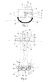
- the figure 1 illustrates a lighting module 1 for equipping a motor vehicle, including being installed inside a front projector of the vehicle.
- This projector is able to emit one or more beams, in particular an optical axis-type beam referenced 9.
- Such a lighting module 1 participates in the implementation of an ADB function, that is to say a selective switching on and off of the light beam of road type.
- This first lighting module 1 ensures the provision of at least a first light beam 2 and a second light beam 3, these beams each forming a rectangular light strip, respectively named first light strip 4 and second light strip 5
- first light strip 4 and second light strip 5 These light bands are here made visible by projection on a screen perpendicular to the optical axis 9 and located 25 meters from the first lighting module 1.
- the first lighting device 1 comprises a support 6 on which are secured at least a first light source 7 and a second light source 8 of substantially rectangular shape.
- a first light source 7 and a second light source 8 of substantially rectangular shape.
- the figure 1 shows a light source of rectangular shape with sharp angles but the invention also covers a rectangular shape with chamfered or rounded angles.
- the first light source 7 and the second light source 8 are of substantially identical dimensions, in particular identical.
- the term “substantially” refers to the case of light sources of similar dimensions but where, for example, manufacturing tolerances would imply a slight difference.
- the first light source 7 generates the first light beam 2 and the second light source 8 generates the second light beam 3.
- the first light source 7 extends in a first direction 12 which defines the length of the first light source.
- This first direction 12 is parallel, and possibly coincidental, with the direction taken by the first beam 2.
- this first light source is 2 mm long, measured in the first direction 12, and 1 mm wide, measured along a line perpendicular to the first line 12.
- such light sources are light-emitting diodes.
- the first light source 7 and the second light source 8 are arranged on the support 6 so as to project a second light strip 5 spaced from the first light strip 4.
- the space which separates this first light strip 4 from the second light strip 5 forms a non-illuminated area by the first lighting module 1, such a space having a width symbolized by the reference E 1 .
- the first lighting module 1 further comprises a reflection means 10 whose function is to collect the light rays emitted by the first light source 7, the second light source 8, and any additional light emitter that can be secured to the support 6
- a reflection means 10 is a reflector, for example a parabolic mirror, elliptical, complex surfaces or cylindrical horizontal axis. In the latter case, the reflector collects the light rays to form a virtual image of the light source, in the form of a band of a given height and a width equal to that of the light source.
- a projection device then projects this image onto the screen at a very great distance (typically more than 25m), the focal length of the projection device and the width of the light source determining the width of the light band, whereas this same focal length and the height of the light source determine the height of the light strip.
- the reflector is arranged so that the virtual image does not offer a distribution of luminance identical to that of the light source, concentrating the beam on the upper part of the light strip.
- a single reflection means 10 makes it possible to send back the light beams emitted by the first light source 7 and by the second light source 8.
- the first lighting module 1 further comprises a projection device 11 whose function is to project the first beam 2, the second beam 3 and possibly all the other beams generated by additional light emitters secured to the support 6.
- a projection device 11 may be a focusing device. It is therefore understood that it is a single projection device which participates in the formation of several light bands, in particular the first light strip 4 and the second light strip 5.
- a device projection 17 is a lens having in particular a cylindrical face and a convex face.
- the second light source 8 is oriented at right angles to the first light source 7.
- the second light source 8 is installed on the support 6 so that a second direction 13 defining its length is oriented in a direction angle between 80 ° and 100 ° relative to the first direction 12.
- a placement and an optimized shape of the light strips 4 and 5 will be obtained if the second direction 13 forms an angle of 90 ° with the first direction 12.
- the first line 12, symbolizing the length of the first light source is substantially perpendicular to a third line 45 passing through a lower edge of each light strip while the second line 13, symbolizing the length of the second light line. light source, is substantially parallel to this third straight line 45.
- This third line 45 is parallel to the horizon.
- the first light source 7 is distinct from the second light source 8.
- a space is formed between these two light sources and this space, combined with the reflection means 10 and the projection device 11, conditions a width of the non-illuminated area located between the first light strip 4 and the second light strip 4.
- the width of the first light strip 4 measured in a direction perpendicular to the optical axis 9 of the headlamp and in the horizontal plane, is referenced L 4 .
- the lighting module 1 is arranged so that the width L 5 of the second light strip 5 is equal to L 8 / I 8 ⁇ L 4 , L 8 corresponding to a length of the second light source 8, I 8 corresponding to a width of the second light source 8, and L 4 being the width of the first light strip 4.
- Such a structure is obtained by the space separating the two light sources once fixed on the support 6.
- the first light band 4 is further defined by its height H 4 , measured in a direction perpendicular to the optical axis 9 of the headlamp and the horizontal plane.
- the second light band 5 is defined by a height H 5 equal to I 8 / L 8 x H 4 .
- Such a structure is obtained in particular by the right angle orientation of the rectangular light sources, of identical dimensions, with respect to each other.
- the ration L / I is equal to 0.5.
- first light source 7 and the second light source 8 each have an edge aligned on the same straight line, such an edge being the one opposite to the reflection means 10 with respect to the light source. In other words, this edge is the one that directly faces the projection device 11. Such an arrangement allows to align a lower edge of each light band.
- the first lighting module 1 is inclined with respect to the optical axis 9 of the projector. More precisely, the lighting module 1 is installed in the headlight so that an inclination 17 is formed, for example between 0.5 and 4 ° between the direction taken by the first beam 2 and the optical axis 9 of the projector, measured in the horizontal plane.
- this inclination 17 chosen at half the opening of the first light beam avoids band deformations. bright.
- the compactness is improved which facilitates the integration of a plurality of lighting modules inside a projector.
- the invention is arranged so that the inclination is coordinated with the opening concerned.
- the figure 1 shows a second lighting module 14 separate from the first lighting module 1, and a third lighting module 15 and a fourth lighting module 16. These four lighting modules are arranged side by side in the same front projector of the vehicle.
- each lighting module comprises two rectangular light sources, possibly of substantially identical dimensions, implanted at right angles, a support receiving said sources, a reflection means and a projection device.
- the arrangement of the second light source on the support varies from one module to another, as do the surfaces of the reflector and the input and output faces of the projection device, in particular the lens.
- the second lighting module 14 forms a symmetry of the first lighting module 1 with respect to the optical axis 9 of the projector.
- the first light source 7 is interposed between the optical axis 9 and the second light source 8, the latter being then to the right of the first light source 7 according to a view from above of the lighting module.
- the first light source 18 of the second lighting module 14 is also interposed between the optical axis 9 and a second light source 19 of the second lighting module 14. Viewed from above, this second light source 19 is then installed to the left of the first light source 18 of the second lighting module 14, forming an angle of between 80 ° and 100 °; and advantageously 90 ° with respect to the first light source 18 of the second lighting module 14.
- Such an arrangement makes it possible to form a third light beam 20 generated by the first light source 18 of the second lighting module, as well as a fourth light beam 21 generated by the second light source 19 of the second lighting module 14.
- the third light beam 20 is at the origin of a third light strip 22 immediately adjacent to the first light strip 14 and the fourth light beam 21 forms a fourth light strip 23.
- the second lighting module 14 is arranged so that a width L 22 of the third light strip 22 is equal to the width L 4 of the first light strip 4.
- a height H 22 of this third light strip 22 is also identical to the height H 4 of the first light strip 4.
- the fourth light strip 23 it is of dimensions equivalent to the dimensions of the second light strip 5.
- the second lighting module 14 comprises means for a height H 23 and a width L 23 of the fourth light strip 23 are equal to the height H 5 and the width L 5 of the second light strip 5.
- the third light strip 22 partially fills the non-illuminated zone formed between the first light strip 4 and the second light strip 5.
- the non-illuminated zone formed between the third light strip 22 and the fourth light strip 23 is also at least partially filled by the presence of the first light strip 4.
- the second lighting module 14 is inclined with respect to the optical axis 9 in an inclination 44 of, for example, between -0.5 and -4 °, advantageously -1 °, the value being chosen to be identical to the value of inclination of the first lighting module 1, with the sign close.
- This inclination 44 is measured between the optical axis 9 of the projector and a line passing through the third light beam 20, in a horizontal plane.
- this inclination 44 chosen at half the opening of the third light beam avoids deformations of light bands.
- the compactness is improved which facilitates the integration of a plurality of lighting modules inside a projector.
- the invention is arranged so that the inclination is coordinated with the opening concerned.
- the third lighting module 15 is installed for example next to the second lighting module 14, the latter being interposed between the third lighting module 15 and the first lighting module 1.
- the structure of the third lighting module and the position of its second light source 24 with respect to its first light source 25 are identical to those described in relation to the first lighting module 1. Reference is therefore made to the explanations related to the first lighting module for know the detail.
- the third lighting module also has an inclination 27 with respect to the optical axis 9 of the projector.
- This inclination 27 is measured between a direction taken by a fifth light beam 26 generated by the first light source 25 of the third lighting module 15 and the optical axis 9, measured in a horizontal plane.
- the value of this inclination is equal to -3 °, especially when the inclination between the third beam 20 and the optical axis 9 is equal to -1 °.
- the first light source 25 of the third lighting module 15, via the fifth light beam 26, generates a fifth light strip 28 of width L 28 equal to the difference between the width of the space between the first light strip 4 and the second light strip 5 and the width L 22 of the third light strip 22.
- This fifth light strip 28 extends in the non-illuminated zone located between the first light strip 4 and the second light strip 5, between the latter and the third light strip 22.
- the zone not illuminated by the first lighting module 1 is thus illuminated in its entirety by the second lighting module 14, in particular via its third light beam 20, combined with the third lighting module 15, via the fifth light beam 26.
- This fifth light strip 28 is also defined by its height referenced H 28 , which is advantageously equal to 3 ⁇ 4 of H 4 , that is to say the height of the first light strip 4. Such a difference in height between the height of the first light strip 4 and that of the fifth light strip 28 results from the reflection means 29 and the projection device 30 assigned to the third lighting module 15.
- the second light source 24 of the third lighting module forms a sixth light beam 31 which projects onto the screen in the form of a sixth light strip 32 immediately adjacent to the second light strip 5, the latter being inserted between the fifth and the sixth light bands.
- L 24 corresponds to a length of the second light source 24 of the third lighting module while I 24 defines a width of the same light source.
- This sixth light strip 32 is defined by a height H 32, advantageously equal to 3/4 of H 5 , or 3/8 of the height H 4 of the first light strip 4 in the preferred configuration. Such a height results from the rectangular character and the orientation between 80 ° and 100 ° of the second light source 24 with respect to the first light source 25 of the third lighting module 15. This height H 32 is also implemented by the reflection means 29 and the projection device 30 of the third lighting module 15.
- a fourth lighting module 16 is installed next to the first lighting module 1, the latter being interposed between this fourth lighting module 16 and the second lighting module 14.
- the structure of the fourth lighting module 16 and the position of its second light source 33 with respect to its first light source 34 are identical to those described in relation to the second lighting module 14. Reference will therefore be made to the explanations relating to this second lighting module to know The detail.
- the fourth lighting module 16 has an inclination 35 with respect to the optical axis 9 of the projector.
- This inclination 35 is measured between a direction taken by a seventh light beam 36 generated by the first light source 34 of the fourth lighting module 16 and the optical axis 9, measured in a horizontal plane.
- the value of this inclination is equal to 3 °, especially when the inclination between the first beam 2 and the optical axis 9 is equal to 1 °.
- the first light source 34 of the fourth lighting module 16 via the seventh light beam 36, generates a seventh light band 37 of width L 37 equal to the difference between the width of the space between the third band 22 luminous and the fourth light strip 23 and the width L 4 of the first light strip 4.
- the invention also covers the case where the width L 37 of the seventh light strip 37 is wider or narrower in size than the first light strip 4 or the third light strip 22.
- This seventh light strip 37 extends in the non-illuminated zone situated between the third light strip 22 and the fourth light strip 23, between the latter and the first light strip 4.
- the zone not illuminated by the second lighting module 14 is thus illuminated entirely by the first lighting module 1, in particular via its first light beam 2, combined with the fourth lighting module 16, via the seventh light beam 36.
- This seventh light band 37 is defined by its height referenced H 37 , which is advantageously equal to 3 ⁇ 4 H 4 , that is to say the height of the first light strip 4. Such a difference between the height of the first 4 and that of the seventh light strip 37 results from the reflection means 38 and the projection device 39 assigned to the fourth lighting module 16.
- the second light source 33 of the fourth lighting module 16 forms an eighth light beam 40 which projects onto the screen in the form of an eighth light band 41 immediately adjacent to the fourth light strip 23, the latter being inserted between the seventh and eighth light band 40.
- L 33 corresponds to a length of the second light source 33 of the fourth lighting module 16 while I 33 defines a width of the same light source.
- This eighth light band 41 is defined by a height H 41 equal for example to 3/8 of the height H 4 of the first light strip 4, in the preferred configuration. Such a height results from the orientation between 80 ° and 100 ° of the second light source 33 with respect to the first light source 34 of the fourth lighting module 16. This height is also implemented by the reflection means 38 and the projection device 39 of the fourth lighting module 16.
- a lighting beam 50 projected by a single projector such a beam having an asymptotic profile particularly suited to the photometric function "road" of a motor vehicle.
- a lighting beam 50 of the projector 50 is implemented by only four lighting modules, all using similar components.
- the reflection means and the projection device are calculated to produce an anamorphosis of the emitter of each light source.
- an average set of reflection - projection device, associated with a light source is calculated to vertically expand the light band produced.
- This embodiment makes it possible to obtain a luminous band with a luminous intensity that is off-center vertically, that is to say away from the center of this luminous band.
- the maximum luminous intensity is positioned, for example, towards the bottom of the light band considered.
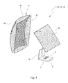
- the figure 2 shows in detail a lighting module according to the invention.
- the items explained below are applicable to the first, second, third, and fourth lighting modules discussed above.
- the first light source 7 and the second light source 8 are of rectangular shape.
- the first light source is thus defined by a length L, parallel to the optical axis, and by a width I perpendicular to the optical axis.
- the second light source 8 is defined by a length L, perpendicular to the optical axis, and by a width I parallel to the optical axis. As the light sources are identical their lengths and the widths are equal.
- the module according to the invention is arranged so that the distance d 1 determines a width E 1 ( figure 1 ) of the light-free space between the first light band and the second light band, such space being filled at least in part by a light emitted by one of the other light modules, as explained above. above.
- the figure 3 shows a different embodiment variant of the figure 1 , in that it comprises only two lighting modules 1, 14 according to the invention and an additional lighting module 60.
- the additional lighting module 60 is for example installed to the left of the second lighting module 14, but it could be placed above, below or separated from the first and second lighting modules 1 and 14.
- the structure of the additional lighting module 60 is similar to that detailed above, in that it comprises a support which receives two light sources, a reflection means and a projection device.
- the first light source 61 and the second light source 62 of the additional module are aligned along axes, for example, parallel.
- a length of the first light source 61 of the additional module 60 is parallel to a length of the second light source 62 of the same module, especially when these sources are of rectangular shape.
- the overall beam 50 is formed by the combination of six light bands, generated two by two by each lighting module.
- the first lighting module 1 thus generates the first light strip 4 and the second light strip 5
- the second lighting module 14 generates the third light strip 22 and the fourth light strip 23
- the additional lighting module 60 generates a first additional light band 63 by means of the first light source 61 and a second additional light band 64 by means of the second light source 62.
- a height H 63 and a width L 63 of the first additional light strip 63 are equal to a height H 64 and a width L 64 of the second additional light strip 64.
- the invention according to this figure 3 is arranged so that the space devoid of light between the first light strip 4 and the second light strip 5 is filled by the third light strip 22 and the first additional light strip 63.
- the lighting modules of this figure are arranged so that the space devoid of light between the first light strip 4 and the fourth light strip 23 is filled by the second additional light strip 64.
- L 63 is the width of the first additional luminous band 63
- L 22 is the width of the third luminous band 22
- E 1 is the width of the space between the first luminous band 4 and the second luminous band 5
- L 4 is the width of the first light band 4
- E 60 is the width of the space between the first additional light band 63 and the second additional light band 64
- d 60 is the distance that separates the first light source 61 from the second source light 62 of the additional module
- L 60 is the length of one of the light sources of the additional module 60
- L 64 is the width of the second band additional light 64
- I 60 is the width of one of the light sources of the additional module 60, preferably identical to the second light source of the same module
- H 63 and H 64 are respectively the height of the first and second additional light bands 63 and 64
- H 22 is the height of the third light strip 22.
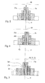
- the figure 4 illustrates an example of constituent components of a lighting module.
- the support 6 is a plate or circuit board which receives on the same face the first light source 7 and the second light source 8. These are light-emitting diodes of rectangular shape.
- the support can also receive electronic components, for example, necessary for the ignition or extinction of these sources, or their protection.
- a shutter 46 Perpendicularly to the plane of extension of the support 6, there is a shutter 46 whose function is to prevent a direct emission of light rays generated by the sources to the projection device 11.
- This shutter may in particular have a non-reflective surface so as to prevent any reflection of the light rays towards the reflection means 10.
- the latter takes, for example, a parabolic or possibly elliptical shape. It may for example be a flat mirror, concave, convex or complex surfaces.
- such a reflection means 10 is a cylindrical mirror of horizontal axis perpendicular to the optical axis, of cross section close to a hyperbola.
- the projection device 11 is for example a lens, especially stigmatic, and having a first wall 47 which faces directly the reflection means 10.
- This first wall 47 is here cylindrical, vertical axis.
- the lens is delimited by a second wall 48 which is opposite the first wall 47 with respect to a body 49 of the lens.
- This second wall 48 has a concave shape seen from the first wall 47.
- the light beams are emitted by the first light source 7 and the second light source 8 and strike a surface of the reflection means 10. The latter redirects them to the projection device 11 to project on the road to be taken by the vehicle.
- the figure 5 illustrates the positioning of the eight light bands generated by four lighting modules and forming a first lighting beam 50 of a first projector installed at the front of a vehicle.
- An index a is given to the references used above to indicate that it is the first projector and an index b is given to these same references for the second projector.
- the lighting modules are arranged in the first projector so that the first light strip 4a and the third light strip 22a are disposed on either side of the optical axis 9.
- the first beam of light lighting 50 is thus centered on the optical axis 9.
- the figure 6 shows a second lighting beam 51 generated by a second projector installed at the front of the vehicle.
- This second illumination beam 51 is made by a plurality of light bands created by four lighting modules identical to those described above, in connection with the first projector.
- This second illumination beam 51 is shifted, for example, to the right by a value equal to half a width of light.
- a first light band 4a generated by a first lighting module installed in the first projector.
- a third light band 22b overlaps the optical axis 9, in particular by passing through the center of the latter, according to its width.
- Such an offset is obtained by tilting the four lighting modules of the second projector by a value equal to 1 °, when the width of the first light band results from a beam of angular aperture equal to 2 °.
- the figure 7 illustrates a global beam emitted by the motor vehicle, that is to say emitted by the first projector and the second projector.
- This overall beam 52 is thus a superposition of the first lighting beam 50 on the second lighting beam 51, the second lighting beam being offset by half a width of the first light strip.
- the figure 7 shows the overall beam 52 in which the fifth light band 28a of the first projector and the fifth light strip 28b of the second projector are off, especially when the presence of a vehicle in this area has been detected. It can be seen that the non-illuminated zone has a width equal to half a width of the first luminous band, this non-illuminated zone then lying between the third light band 22a generated by the first projector and the second light strip 5b generated by the second projector.
- the resolution of the ADB function is improved, which increases the driver's illuminated field of vision, without dazzling the driver. of the detected vehicle, by means of a reduced number of lighting modules compared to the device of the prior art.
- the widths are measured in a horizontal direction while the heights are measured in a vertical direction.
Applications Claiming Priority (1)
| Application Number | Priority Date | Filing Date | Title |
|---|---|---|---|
| FR1161904A FR2984457B1 (fr) | 2011-12-19 | 2011-12-19 | Module d'eclairage comprenant au moins deux sources lumineuses installees de maniere sensiblement orthogonale |
Publications (2)
| Publication Number | Publication Date |
|---|---|
| EP2607165A1 true EP2607165A1 (de) | 2013-06-26 |
| EP2607165B1 EP2607165B1 (de) | 2017-09-06 |
Family
ID=47297053
Family Applications (1)
| Application Number | Title | Priority Date | Filing Date |
|---|---|---|---|
| EP12196872.1A Active EP2607165B1 (de) | 2011-12-19 | 2012-12-13 | Beleuchtungsmodul mit zumindest zwei im wesentlich senkrecht zueinander angeordneten Lichtquellen |
Country Status (3)
| Country | Link |
|---|---|
| EP (1) | EP2607165B1 (de) |
| JP (1) | JP6104592B2 (de) |
| FR (1) | FR2984457B1 (de) |
Cited By (8)
| Publication number | Priority date | Publication date | Assignee | Title |
|---|---|---|---|---|
| WO2015014793A1 (fr) * | 2013-08-02 | 2015-02-05 | Valeo Vision | Projecteur et système d'éclairage notamment pour véhicule automobile |
| DE102014200368A1 (de) * | 2014-01-10 | 2015-07-16 | Automotive Lighting Reutlingen Gmbh | Teilfernlicht-Projektionslichtmodul für einen Kraftfahrzeugscheinwerfer |
| EP2944514A1 (de) * | 2014-05-13 | 2015-11-18 | Valeo Vision | Beleuchtungsmodul für kraftfahrzeugscheinwerfer, das mehrere lichtquellen umfasst |
| FR3043168A1 (fr) * | 2015-11-02 | 2017-05-05 | Valeo Vision | Dispositif de projection de faisceau lumineux d’un vehicule automobile configure pour projeter une image pixelisee |
| EP3428513A1 (de) * | 2017-07-13 | 2019-01-16 | Valeo Vision | Beleuchtungsvorrichtung, die zwei vertikal versetzte leuchtpixel-matrizen projiziert |
| EP3489575A1 (de) * | 2017-11-22 | 2019-05-29 | Stanley Electric Co., Ltd. | Fahrzeugscheinwerfer |
| WO2021046940A1 (zh) * | 2019-09-11 | 2021-03-18 | 华域视觉科技(上海)有限公司 | 一种车灯模组、车灯及车辆 |
| WO2021046939A1 (zh) * | 2019-09-11 | 2021-03-18 | 华域视觉科技(上海)有限公司 | 一种车灯模组、车灯及车辆 |
Families Citing this family (3)
| Publication number | Priority date | Publication date | Assignee | Title |
|---|---|---|---|---|
| JP6271292B2 (ja) * | 2014-02-25 | 2018-01-31 | 株式会社小糸製作所 | 車両用灯具 |
| KR102483571B1 (ko) * | 2016-04-11 | 2023-01-02 | 현대모비스 주식회사 | 차량용 램프 |
| CN113874653A (zh) * | 2019-05-22 | 2021-12-31 | 株式会社小糸制作所 | 车辆用前照灯 |
Citations (7)
| Publication number | Priority date | Publication date | Assignee | Title |
|---|---|---|---|---|
| DE202007018181U1 (de) * | 2007-12-31 | 2008-05-08 | Automotive Lighting Reutlingen Gmbh | Projektionsmodul mit dynamischer Kurvenlichtfunktion |
| EP2037167A2 (de) * | 2007-09-13 | 2009-03-18 | Koito Manufacturing Co., Ltd. | Lampeneinheit für Fahrzeugscheinwerfer und Fahrzeugscheinwerfer |
| JP2010067417A (ja) * | 2008-09-09 | 2010-03-25 | Koito Mfg Co Ltd | 車両用前照灯装置 |
| EP2184532A2 (de) * | 2008-11-10 | 2010-05-12 | Koito Manufacturing Co., Ltd. | Beleuchtungseinheit |
| EP2278217A1 (de) | 2009-07-21 | 2011-01-26 | Valeo Vision | Beleuchtungsmodul für Fahrzeugscheinwerfer, und mit wenigstens einem solchen Modul ausgerüsteter Scheinwerfer |
| EP2280215A2 (de) * | 2009-07-31 | 2011-02-02 | Zizala Lichtsysteme GmbH | LED-Kraftfahrzeugscheinwerfer zur Erzeugung einer dynamischen Lichtverteilung |
| JP2011081968A (ja) * | 2009-10-05 | 2011-04-21 | Koito Mfg Co Ltd | 車両用灯具 |
Family Cites Families (4)
| Publication number | Priority date | Publication date | Assignee | Title |
|---|---|---|---|---|
| JP5226985B2 (ja) * | 2007-08-22 | 2013-07-03 | 株式会社小糸製作所 | 車輌用前照灯 |
| JP5255301B2 (ja) * | 2008-03-12 | 2013-08-07 | 株式会社小糸製作所 | 車両用前照灯装置 |
| JP5280074B2 (ja) * | 2008-03-14 | 2013-09-04 | 株式会社小糸製作所 | 車両用前照灯装置 |
| JP5574751B2 (ja) * | 2010-02-25 | 2014-08-20 | スタンレー電気株式会社 | 車両用前照灯およびそれに用いられるledパッケージ |
-
2011
- 2011-12-19 FR FR1161904A patent/FR2984457B1/fr active Active
-
2012
- 2012-12-13 EP EP12196872.1A patent/EP2607165B1/de active Active
- 2012-12-18 JP JP2012275422A patent/JP6104592B2/ja active Active
Patent Citations (7)
| Publication number | Priority date | Publication date | Assignee | Title |
|---|---|---|---|---|
| EP2037167A2 (de) * | 2007-09-13 | 2009-03-18 | Koito Manufacturing Co., Ltd. | Lampeneinheit für Fahrzeugscheinwerfer und Fahrzeugscheinwerfer |
| DE202007018181U1 (de) * | 2007-12-31 | 2008-05-08 | Automotive Lighting Reutlingen Gmbh | Projektionsmodul mit dynamischer Kurvenlichtfunktion |
| JP2010067417A (ja) * | 2008-09-09 | 2010-03-25 | Koito Mfg Co Ltd | 車両用前照灯装置 |
| EP2184532A2 (de) * | 2008-11-10 | 2010-05-12 | Koito Manufacturing Co., Ltd. | Beleuchtungseinheit |
| EP2278217A1 (de) | 2009-07-21 | 2011-01-26 | Valeo Vision | Beleuchtungsmodul für Fahrzeugscheinwerfer, und mit wenigstens einem solchen Modul ausgerüsteter Scheinwerfer |
| EP2280215A2 (de) * | 2009-07-31 | 2011-02-02 | Zizala Lichtsysteme GmbH | LED-Kraftfahrzeugscheinwerfer zur Erzeugung einer dynamischen Lichtverteilung |
| JP2011081968A (ja) * | 2009-10-05 | 2011-04-21 | Koito Mfg Co Ltd | 車両用灯具 |
Cited By (18)
| Publication number | Priority date | Publication date | Assignee | Title |
|---|---|---|---|---|
| CN105452759B (zh) * | 2013-08-02 | 2018-06-22 | 法雷奥照明公司 | 特别用于机动车辆的投射器和照明系统 |
| FR3009366A1 (fr) * | 2013-08-02 | 2015-02-06 | Valeo Vision | Projecteur et systeme d'eclairage notamment pour vehicule automobile |
| US10077879B2 (en) | 2013-08-02 | 2018-09-18 | Valeo Vision | Vehicle headlamp system |
| WO2015014793A1 (fr) * | 2013-08-02 | 2015-02-05 | Valeo Vision | Projecteur et système d'éclairage notamment pour véhicule automobile |
| CN105452759A (zh) * | 2013-08-02 | 2016-03-30 | 法雷奥照明公司 | 特别用于机动车辆的投射器和照明系统 |
| DE102014200368A1 (de) * | 2014-01-10 | 2015-07-16 | Automotive Lighting Reutlingen Gmbh | Teilfernlicht-Projektionslichtmodul für einen Kraftfahrzeugscheinwerfer |
| DE102014200368B4 (de) * | 2014-01-10 | 2016-01-21 | Automotive Lighting Reutlingen Gmbh | Teilfernlicht-Projektionslichtmodul für einen Kraftfahrzeugscheinwerfer |
| FR3021092A1 (fr) * | 2014-05-13 | 2015-11-20 | Valeo Vision | Systeme d'eclairage pour projecteur de vehicule automobile comprenant plusieurs modules d'eclairage |
| EP2944514A1 (de) * | 2014-05-13 | 2015-11-18 | Valeo Vision | Beleuchtungsmodul für kraftfahrzeugscheinwerfer, das mehrere lichtquellen umfasst |
| FR3043168A1 (fr) * | 2015-11-02 | 2017-05-05 | Valeo Vision | Dispositif de projection de faisceau lumineux d’un vehicule automobile configure pour projeter une image pixelisee |
| EP3428513A1 (de) * | 2017-07-13 | 2019-01-16 | Valeo Vision | Beleuchtungsvorrichtung, die zwei vertikal versetzte leuchtpixel-matrizen projiziert |
| FR3069045A1 (fr) * | 2017-07-13 | 2019-01-18 | Valeo Vision | Dispositif d'eclairage projetant deux matrices de pixels lumineux decalees verticalement |
| US10913387B2 (en) | 2017-07-13 | 2021-02-09 | Valeo Vision | Lighting device projecting two vertically offset matrices of light pixels |
| EP3489575A1 (de) * | 2017-11-22 | 2019-05-29 | Stanley Electric Co., Ltd. | Fahrzeugscheinwerfer |
| US10851959B2 (en) | 2017-11-22 | 2020-12-01 | Stanley Electric Co., Ltd. | Vehicle headlight |
| WO2021046940A1 (zh) * | 2019-09-11 | 2021-03-18 | 华域视觉科技(上海)有限公司 | 一种车灯模组、车灯及车辆 |
| WO2021046939A1 (zh) * | 2019-09-11 | 2021-03-18 | 华域视觉科技(上海)有限公司 | 一种车灯模组、车灯及车辆 |
| US11519578B2 (en) | 2019-09-11 | 2022-12-06 | Hasco Vision Technology Co., Ltd. | Vehicle lamp assembly, vehicle lamp, and vehicle |
Also Published As
| Publication number | Publication date |
|---|---|
| FR2984457A1 (fr) | 2013-06-21 |
| EP2607165B1 (de) | 2017-09-06 |
| JP6104592B2 (ja) | 2017-03-29 |
| JP2013127968A (ja) | 2013-06-27 |
| FR2984457B1 (fr) | 2023-08-11 |
Similar Documents
| Publication | Publication Date | Title |
|---|---|---|
| EP2607165B1 (de) | Beleuchtungsmodul mit zumindest zwei im wesentlich senkrecht zueinander angeordneten Lichtquellen | |
| EP2856009B1 (de) | Beleuchtungsmodul mit beabstandeten lichtquellen zur implementierung einer abd-funktion | |
| EP2871406B1 (de) | Optisches Hauptelement, Beleuchtungsmodul und Scheinwerfer für Kraftfahrzeug | |
| EP3002504A2 (de) | Leuchtmodul zur beleuchtung und/oder signalisierung für kraftfahrzeug | |
| FR2995967B1 (fr) | Module d'eclairage, notamment pour vehicule automobile | |
| EP2607164B1 (de) | Leuchtmodul zur Erzeugung von verflochtenen bandförmigen Leuchtbereichen | |
| FR3009366A1 (fr) | Projecteur et systeme d'eclairage notamment pour vehicule automobile | |
| FR3002022A1 (fr) | Dispositif d'eclairage et/ou de signalisation a lentille torique | |
| FR3093788A1 (fr) | Dispositif lumineux imageant une surface eclairee virtuelle d’un collecteur | |
| FR3118124A1 (fr) | Module d’éclairage automobile bi-fonction avec eclairage de la lentille d’un module d’eclairage inactif | |
| EP3030830B1 (de) | Signalisierungs- und/oder beleuchtungsvorrichtung für kraftfahrzeuge | |
| EP4051954B1 (de) | Zwischen links- und rechtslenker verstellbarer automobilscheinwerfer | |
| WO2019229191A1 (fr) | Module lumineux pour véhicule automobile, et dispositif d'éclairage et/ou de signalisation muni d'un tel module | |
| EP2436968B1 (de) | Vorrichtung zur Ausstrahlung von Licht für einen Autoscheinwerfer | |
| WO2022162180A1 (fr) | Dispositif d'éclairage de la route d'un véhicule automobile | |
| EP2472176B1 (de) | Beleuchtungs- und/oder signalisierungsvorrichtung, insbesondere für kraftfahrzeug | |
| EP2853804B1 (de) | Beleuchtungs- und/oder signalisierungsmodul mit mehreren drehbaren optischen systemen | |
| WO2023030808A1 (fr) | Module lumineux pour vehicule automobile | |
| WO2023031344A1 (fr) | Dispositif lumineux d'un véhicule automobile | |
| WO2024061970A1 (fr) | Module lumineux | |
| WO2021099290A1 (fr) | Module d'eclairage pour vehicule a coupure modulable entre conduite a gauche et conduite a droite | |
| WO2024023300A1 (fr) | Module lumineux pour dispositif d'éclairage d'un véhicule | |
| FR2995662A1 (fr) | Module et dispositif d'eclairage pour vehicule automobile |
Legal Events
| Date | Code | Title | Description |
|---|---|---|---|
| AK | Designated contracting states |
Kind code of ref document: A1 Designated state(s): AL AT BE BG CH CY CZ DE DK EE ES FI FR GB GR HR HU IE IS IT LI LT LU LV MC MK MT NL NO PL PT RO RS SE SI SK SM TR |
|
| AX | Request for extension of the european patent |
Extension state: BA ME |
|
| PUAI | Public reference made under article 153(3) epc to a published international application that has entered the european phase |
Free format text: ORIGINAL CODE: 0009012 |
|
| 17P | Request for examination filed |
Effective date: 20131213 |
|
| RBV | Designated contracting states (corrected) |
Designated state(s): AL AT BE BG CH CY CZ DE DK EE ES FI FR GB GR HR HU IE IS IT LI LT LU LV MC MK MT NL NO PL PT RO RS SE SI SK SM TR |
|
| GRAP | Despatch of communication of intention to grant a patent |
Free format text: ORIGINAL CODE: EPIDOSNIGR1 |
|
| RIC1 | Information provided on ipc code assigned before grant |
Ipc: F21S 8/10 20060101ALI20170322BHEP Ipc: B60Q 1/00 20060101AFI20170322BHEP Ipc: F21S 8/12 20060101ALI20170322BHEP |
|
| INTG | Intention to grant announced |
Effective date: 20170425 |
|
| GRAS | Grant fee paid |
Free format text: ORIGINAL CODE: EPIDOSNIGR3 |
|
| GRAA | (expected) grant |
Free format text: ORIGINAL CODE: 0009210 |
|
| AK | Designated contracting states |
Kind code of ref document: B1 Designated state(s): AL AT BE BG CH CY CZ DE DK EE ES FI FR GB GR HR HU IE IS IT LI LT LU LV MC MK MT NL NO PL PT RO RS SE SI SK SM TR |
|
| REG | Reference to a national code |
Ref country code: GB Ref legal event code: FG4D Free format text: NOT ENGLISH |
|
| REG | Reference to a national code |
Ref country code: CH Ref legal event code: EP Ref country code: AT Ref legal event code: REF Ref document number: 925482 Country of ref document: AT Kind code of ref document: T Effective date: 20170915 |
|
| REG | Reference to a national code |
Ref country code: IE Ref legal event code: FG4D Free format text: LANGUAGE OF EP DOCUMENT: FRENCH |
|
| REG | Reference to a national code |
Ref country code: DE Ref legal event code: R096 Ref document number: 602012036869 Country of ref document: DE |
|
| REG | Reference to a national code |
Ref country code: FR Ref legal event code: PLFP Year of fee payment: 6 |
|
| REG | Reference to a national code |
Ref country code: NL Ref legal event code: MP Effective date: 20170906 |
|
| REG | Reference to a national code |
Ref country code: LT Ref legal event code: MG4D |
|
| PG25 | Lapsed in a contracting state [announced via postgrant information from national office to epo] |
Ref country code: LT Free format text: LAPSE BECAUSE OF FAILURE TO SUBMIT A TRANSLATION OF THE DESCRIPTION OR TO PAY THE FEE WITHIN THE PRESCRIBED TIME-LIMIT Effective date: 20170906 Ref country code: HR Free format text: LAPSE BECAUSE OF FAILURE TO SUBMIT A TRANSLATION OF THE DESCRIPTION OR TO PAY THE FEE WITHIN THE PRESCRIBED TIME-LIMIT Effective date: 20170906 Ref country code: SE Free format text: LAPSE BECAUSE OF FAILURE TO SUBMIT A TRANSLATION OF THE DESCRIPTION OR TO PAY THE FEE WITHIN THE PRESCRIBED TIME-LIMIT Effective date: 20170906 Ref country code: FI Free format text: LAPSE BECAUSE OF FAILURE TO SUBMIT A TRANSLATION OF THE DESCRIPTION OR TO PAY THE FEE WITHIN THE PRESCRIBED TIME-LIMIT Effective date: 20170906 Ref country code: NO Free format text: LAPSE BECAUSE OF FAILURE TO SUBMIT A TRANSLATION OF THE DESCRIPTION OR TO PAY THE FEE WITHIN THE PRESCRIBED TIME-LIMIT Effective date: 20171206 |
|
| REG | Reference to a national code |
Ref country code: AT Ref legal event code: MK05 Ref document number: 925482 Country of ref document: AT Kind code of ref document: T Effective date: 20170906 |
|
| PG25 | Lapsed in a contracting state [announced via postgrant information from national office to epo] |
Ref country code: BG Free format text: LAPSE BECAUSE OF FAILURE TO SUBMIT A TRANSLATION OF THE DESCRIPTION OR TO PAY THE FEE WITHIN THE PRESCRIBED TIME-LIMIT Effective date: 20171206 Ref country code: ES Free format text: LAPSE BECAUSE OF FAILURE TO SUBMIT A TRANSLATION OF THE DESCRIPTION OR TO PAY THE FEE WITHIN THE PRESCRIBED TIME-LIMIT Effective date: 20170906 Ref country code: GR Free format text: LAPSE BECAUSE OF FAILURE TO SUBMIT A TRANSLATION OF THE DESCRIPTION OR TO PAY THE FEE WITHIN THE PRESCRIBED TIME-LIMIT Effective date: 20171207 Ref country code: LV Free format text: LAPSE BECAUSE OF FAILURE TO SUBMIT A TRANSLATION OF THE DESCRIPTION OR TO PAY THE FEE WITHIN THE PRESCRIBED TIME-LIMIT Effective date: 20170906 Ref country code: RS Free format text: LAPSE BECAUSE OF FAILURE TO SUBMIT A TRANSLATION OF THE DESCRIPTION OR TO PAY THE FEE WITHIN THE PRESCRIBED TIME-LIMIT Effective date: 20170906 |
|
| PG25 | Lapsed in a contracting state [announced via postgrant information from national office to epo] |
Ref country code: NL Free format text: LAPSE BECAUSE OF FAILURE TO SUBMIT A TRANSLATION OF THE DESCRIPTION OR TO PAY THE FEE WITHIN THE PRESCRIBED TIME-LIMIT Effective date: 20170906 |
|
| PG25 | Lapsed in a contracting state [announced via postgrant information from national office to epo] |
Ref country code: PL Free format text: LAPSE BECAUSE OF FAILURE TO SUBMIT A TRANSLATION OF THE DESCRIPTION OR TO PAY THE FEE WITHIN THE PRESCRIBED TIME-LIMIT Effective date: 20170906 Ref country code: RO Free format text: LAPSE BECAUSE OF FAILURE TO SUBMIT A TRANSLATION OF THE DESCRIPTION OR TO PAY THE FEE WITHIN THE PRESCRIBED TIME-LIMIT Effective date: 20170906 Ref country code: CZ Free format text: LAPSE BECAUSE OF FAILURE TO SUBMIT A TRANSLATION OF THE DESCRIPTION OR TO PAY THE FEE WITHIN THE PRESCRIBED TIME-LIMIT Effective date: 20170906 |
|
| PG25 | Lapsed in a contracting state [announced via postgrant information from national office to epo] |
Ref country code: SM Free format text: LAPSE BECAUSE OF FAILURE TO SUBMIT A TRANSLATION OF THE DESCRIPTION OR TO PAY THE FEE WITHIN THE PRESCRIBED TIME-LIMIT Effective date: 20170906 Ref country code: AT Free format text: LAPSE BECAUSE OF FAILURE TO SUBMIT A TRANSLATION OF THE DESCRIPTION OR TO PAY THE FEE WITHIN THE PRESCRIBED TIME-LIMIT Effective date: 20170906 Ref country code: IS Free format text: LAPSE BECAUSE OF FAILURE TO SUBMIT A TRANSLATION OF THE DESCRIPTION OR TO PAY THE FEE WITHIN THE PRESCRIBED TIME-LIMIT Effective date: 20180106 Ref country code: EE Free format text: LAPSE BECAUSE OF FAILURE TO SUBMIT A TRANSLATION OF THE DESCRIPTION OR TO PAY THE FEE WITHIN THE PRESCRIBED TIME-LIMIT Effective date: 20170906 Ref country code: SK Free format text: LAPSE BECAUSE OF FAILURE TO SUBMIT A TRANSLATION OF THE DESCRIPTION OR TO PAY THE FEE WITHIN THE PRESCRIBED TIME-LIMIT Effective date: 20170906 Ref country code: IT Free format text: LAPSE BECAUSE OF FAILURE TO SUBMIT A TRANSLATION OF THE DESCRIPTION OR TO PAY THE FEE WITHIN THE PRESCRIBED TIME-LIMIT Effective date: 20170906 |
|
| REG | Reference to a national code |
Ref country code: DE Ref legal event code: R097 Ref document number: 602012036869 Country of ref document: DE |
|
| PLBE | No opposition filed within time limit |
Free format text: ORIGINAL CODE: 0009261 |
|
| STAA | Information on the status of an ep patent application or granted ep patent |
Free format text: STATUS: NO OPPOSITION FILED WITHIN TIME LIMIT |
|
| PG25 | Lapsed in a contracting state [announced via postgrant information from national office to epo] |
Ref country code: DK Free format text: LAPSE BECAUSE OF FAILURE TO SUBMIT A TRANSLATION OF THE DESCRIPTION OR TO PAY THE FEE WITHIN THE PRESCRIBED TIME-LIMIT Effective date: 20170906 |
|
| REG | Reference to a national code |
Ref country code: CH Ref legal event code: PL |
|
| 26N | No opposition filed |
Effective date: 20180607 |
|
| GBPC | Gb: european patent ceased through non-payment of renewal fee |
Effective date: 20171213 |
|
| PG25 | Lapsed in a contracting state [announced via postgrant information from national office to epo] |
Ref country code: SI Free format text: LAPSE BECAUSE OF FAILURE TO SUBMIT A TRANSLATION OF THE DESCRIPTION OR TO PAY THE FEE WITHIN THE PRESCRIBED TIME-LIMIT Effective date: 20170906 |
|
| REG | Reference to a national code |
Ref country code: IE Ref legal event code: MM4A |
|
| PG25 | Lapsed in a contracting state [announced via postgrant information from national office to epo] |
Ref country code: LU Free format text: LAPSE BECAUSE OF NON-PAYMENT OF DUE FEES Effective date: 20171213 Ref country code: MT Free format text: LAPSE BECAUSE OF FAILURE TO SUBMIT A TRANSLATION OF THE DESCRIPTION OR TO PAY THE FEE WITHIN THE PRESCRIBED TIME-LIMIT Effective date: 20170906 |
|
| REG | Reference to a national code |
Ref country code: BE Ref legal event code: MM Effective date: 20171231 |
|
| PG25 | Lapsed in a contracting state [announced via postgrant information from national office to epo] |
Ref country code: IE Free format text: LAPSE BECAUSE OF NON-PAYMENT OF DUE FEES Effective date: 20171213 |
|
| PG25 | Lapsed in a contracting state [announced via postgrant information from national office to epo] |
Ref country code: BE Free format text: LAPSE BECAUSE OF NON-PAYMENT OF DUE FEES Effective date: 20171231 Ref country code: CH Free format text: LAPSE BECAUSE OF NON-PAYMENT OF DUE FEES Effective date: 20171231 Ref country code: GB Free format text: LAPSE BECAUSE OF NON-PAYMENT OF DUE FEES Effective date: 20171213 Ref country code: LI Free format text: LAPSE BECAUSE OF NON-PAYMENT OF DUE FEES Effective date: 20171231 |
|
| PG25 | Lapsed in a contracting state [announced via postgrant information from national office to epo] |
Ref country code: MC Free format text: LAPSE BECAUSE OF FAILURE TO SUBMIT A TRANSLATION OF THE DESCRIPTION OR TO PAY THE FEE WITHIN THE PRESCRIBED TIME-LIMIT Effective date: 20170906 Ref country code: HU Free format text: LAPSE BECAUSE OF FAILURE TO SUBMIT A TRANSLATION OF THE DESCRIPTION OR TO PAY THE FEE WITHIN THE PRESCRIBED TIME-LIMIT; INVALID AB INITIO Effective date: 20121213 |
|
| PG25 | Lapsed in a contracting state [announced via postgrant information from national office to epo] |
Ref country code: CY Free format text: LAPSE BECAUSE OF NON-PAYMENT OF DUE FEES Effective date: 20170906 |
|
| PG25 | Lapsed in a contracting state [announced via postgrant information from national office to epo] |
Ref country code: MK Free format text: LAPSE BECAUSE OF FAILURE TO SUBMIT A TRANSLATION OF THE DESCRIPTION OR TO PAY THE FEE WITHIN THE PRESCRIBED TIME-LIMIT Effective date: 20170906 |
|
| PG25 | Lapsed in a contracting state [announced via postgrant information from national office to epo] |
Ref country code: TR Free format text: LAPSE BECAUSE OF FAILURE TO SUBMIT A TRANSLATION OF THE DESCRIPTION OR TO PAY THE FEE WITHIN THE PRESCRIBED TIME-LIMIT Effective date: 20170906 |
|
| PG25 | Lapsed in a contracting state [announced via postgrant information from national office to epo] |
Ref country code: PT Free format text: LAPSE BECAUSE OF FAILURE TO SUBMIT A TRANSLATION OF THE DESCRIPTION OR TO PAY THE FEE WITHIN THE PRESCRIBED TIME-LIMIT Effective date: 20170906 |
|
| PG25 | Lapsed in a contracting state [announced via postgrant information from national office to epo] |
Ref country code: AL Free format text: LAPSE BECAUSE OF FAILURE TO SUBMIT A TRANSLATION OF THE DESCRIPTION OR TO PAY THE FEE WITHIN THE PRESCRIBED TIME-LIMIT Effective date: 20170906 |
|
| P01 | Opt-out of the competence of the unified patent court (upc) registered |
Effective date: 20230528 |
|
| PGFP | Annual fee paid to national office [announced via postgrant information from national office to epo] |
Ref country code: FR Payment date: 20231220 Year of fee payment: 12 Ref country code: DE Payment date: 20231208 Year of fee payment: 12 |