EP2607162A2 - Method for producing and/or converting a fixing device for fixing cargo in a cargo space - Google Patents
Method for producing and/or converting a fixing device for fixing cargo in a cargo space Download PDFInfo
- Publication number
- EP2607162A2 EP2607162A2 EP12198100.5A EP12198100A EP2607162A2 EP 2607162 A2 EP2607162 A2 EP 2607162A2 EP 12198100 A EP12198100 A EP 12198100A EP 2607162 A2 EP2607162 A2 EP 2607162A2
- Authority
- EP
- European Patent Office
- Prior art keywords
- rail
- base
- retainer
- fastening device
- cargo
- Prior art date
- Legal status (The legal status is an assumption and is not a legal conclusion. Google has not performed a legal analysis and makes no representation as to the accuracy of the status listed.)
- Granted
Links
- 238000004519 manufacturing process Methods 0.000 title claims abstract description 4
- 238000000034 method Methods 0.000 claims abstract description 15
- 238000006243 chemical reaction Methods 0.000 claims 1
- 238000002407 reforming Methods 0.000 abstract 1
- 238000003780 insertion Methods 0.000 description 7
- 230000037431 insertion Effects 0.000 description 7
- 238000004146 energy storage Methods 0.000 description 2
- 238000006073 displacement reaction Methods 0.000 description 1
- 238000005516 engineering process Methods 0.000 description 1
- 238000002372 labelling Methods 0.000 description 1
- 239000002184 metal Substances 0.000 description 1
Images


Classifications
-
- B—PERFORMING OPERATIONS; TRANSPORTING
- B60—VEHICLES IN GENERAL
- B60P—VEHICLES ADAPTED FOR LOAD TRANSPORTATION OR TO TRANSPORT, TO CARRY, OR TO COMPRISE SPECIAL LOADS OR OBJECTS
- B60P7/00—Securing or covering of load on vehicles
- B60P7/06—Securing of load
- B60P7/08—Securing to the vehicle floor or sides
- B60P7/0807—Attachment points
Definitions
- the invention relates to a method for producing and / or converting a fastening device for fixing cargo in a cargo hold according to the preamble of claim 1, as well as a kit for carrying out this method and corresponding fastening devices.
- fasteners are known in a variety of forms and designs and on the market. Only for example will be on the EP 1 794 053 A1 referenced in which a device for fixing an object to a rail by means of a fitting which is movable with a slider along the rail in a groove and having a retainer which in at least one lateral groove recess in the rail can be lowered, wherein the retainer is connected via a rotatable connecting element with the slider.
- the retainer is supported relative to the slider and / or relative to the rotary member via at least one energy storage and holds the pressurized retainer in at least two heights against the rail firmly.
- a similar slider which is guided along a rail and in which a bolt is integrated for retraction into a rail recess, which is held under the pressure of a spring in latching position, is for example from DE 203 06 549 U1 known.
- a device for temporary connection of an object with a holding or rail profile in which approximately parallel to the longitudinal axis of an undercut longitudinal groove which is provided with axially spaced holes, between each of which a pair of the longitudinal groove laterally limiting and whose undercut overlapping groove edges is arranged. It should be lockable and releasably insertable in the longitudinal groove, wherein the serving as an intermediate element insert is formed insertable into adjacent holes of the rail profile, that a plate-like support surface dominates the surface of the rail profile and on the other hand, at least one Kragorgan of the insert element, the lower surface of the Nutkanten forming ribs of the rail profile engages under.
- the object of the present invention is to provide a method, a kit for carrying out this method and corresponding fastening devices, which are extremely versatile and with a minimum of individual parts a maximum of functions and Products, which can significantly reduce costs.
- the basic idea of the present invention is to provide fastening devices of the above mentioned type. To create a kind of collection that is composed of as few individual elements as possible, but can accommodate different requirements. Depending on these different requirements, the fastening devices can be assembled and made available to the customer. The requirements are based on the rails themselves. This means that the base elements must be adapted to these rails. In today's fastening technology, especially in the cargo holds of vehicles, for example so-called airline rails or keyhole rails are used. Depending on their design, the base element is formed.
- a retainer which serves to fix the base element in an airline rail, has a different configuration than a retainer for, for example, a keyhole rail.
- the retainer consists of an always constant body in which only a different locking element is used, depending on whether the attachment device is suitable for an airline rail or for a keyhole rail.
- the retainer serves to fix the base element in relation to the rail. For this reason, the retainer is usually formed vertically displaceable relative to the base member. In lock position, he drives with corresponding Riegelhesschen in recesses of the rail, however, it should then also be designed to be liftable vertically again, so that this locking position can be solved.
- the whole thing is preferably done against the force of an energy storage device, for example against the force of a coil spring.
- fasteners There are fasteners on which, for example, a lashing strap is to be determined.
- the connecting element is designed as a bracket.
- Other fasteners should have a bolt to be inserted into a blind hole in the load.
- Other connecting elements are bar shoe-like, formed for example for locking bar.
- all connecting elements have in common that they are preferably connected by a pin to the base element.
- the connecting element engages between two tabs of the base element, wherein a passage of the connecting element congruent with one opening in the tab. Through these two openings and the passage in the connecting element, a pin can be inserted.
- the pin is designed as a dowel pin.
- he has a longitudinal slot, whereby a diameter of the pin can be reduced. If the pin then sits in the locked position, it expands again, which avoids clattering of the connecting element relative to the base element.
- This may be, for example, a company logo of a particular company, in particular the company using the fastening device.
- the pin is designed as a quick release.
- the pin may be formed as an Allen and have a certain cross section, which cooperates with a matching cross section of the passages, so that a tension takes place.
- Many possibilities are conceivable here and should be covered by the present invention.
- kits of the various o.g. Elements for carrying out the method has a plurality of different base elements and retainers, which are provided for different rails, as well as a plurality of different connecting elements for different loads.
- the inventive concept also includes a fastening device that has been produced by the method according to the invention.
- connection element is connected to the base element in the manner described above, ie in which the base element has at least two, preferably four congruent openings and the connecting element between the at least two, preferably four openings engages and has a passage connecting the openings, wherein a pin is inserted through the openings and the passage.
- the connecting element has a gimbal-like movable head.
- the connecting element consists of a bridge element, from which a rotary piece rises, which is rotatable relative to the bridge element. This turntable then sits in turn a fork-shaped hat, which is rotatable about a horizontal axis relative to the rotating piece.
- An attachment device P1 for securing cargo in a cargo compartment has a base element 1 for insertion into a cargo compartment
- FIG. 2 shown rail 23.1 and a retainer 2 for locking the base member 1 on the rail and a connecting element 3 to the load.
- the base member 1 is intended for insertion into a so-called airline rail 23.1, as this example in the DE 100 36 553 A1 is described.
- This airline rail is characterized by opposing wave-shaped groove edges 24.1 and 24.2, which form insertion openings 25 for clamping feet 4.1, 4.2 and 4.3, wherein the base member 1 can be moved along the rail groove and thereby reach the clamping feet 4.1 to 4.3 under areas between the insertion openings , whereby the base member 1 is set in the airline rail.
- This position is then secured by a locking element 5.1, which in turn has latching feet 6.1 to 6.4, which retract into adjacent insertion opening of the airline rail. This is done under the pressure of a coil spring 7.
- the bolt feet 6.1-6.4 are at least partially adapted to the contours of the insert opening and tapered downwards formed, whereby the entire fastener P1 is set fairly rattle on the rail 23.
- the locking element 5.1 is inserted into a main body 8 of the retainer 2 and the entire retainer 2 together with the locking element 5.1 vertically along the base member 1 feasible.
- a guide element e.g. a pin to enforce a corresponding guide opening in the locking element 5.1.
- the coil spring 7 presses on the one hand on the locking element 5.1, on the other hand it is supported against an abutment 11, which is fixed together with the connecting element 3 to the base element 1.
- four tabs 12.1 to 12.4 protrude from the base element 1, each having an opening 13.1 to 13.4.
- the connecting element 3 or a bow-shaped body 18 has in its end regions in each case a passage 14.1 and 14.2, which are arranged in the position of use between two lugs 12.1, 12.2 and 12.3, 12.4 and with the openings 13.1, 13.2 and 13.3, 13.4 congruent.
- Secured is the connecting element 3 by means of pins 15.1 and 15.2, which are inserted through the opening 13.1, the passage 14.1 and the opening 13.2 and an opening 13.4, 14.2, and 13.3.
- These pins are designed as dowel pins.
- they have a longitudinal slot, not shown in detail, whereby 15.1 and 15.2, the diameter can be reduced during insertion of the pins, but then spread in the position of use and so brace in the openings or passages.
- pins 15.1 and 15.2 can end whilrtig a label 17.1 and 17.2 be assigned, which is done for the sake of simplicity, that corresponding extensions are inserted at the markings 17.1 and 17.2 in the front opening of the sleeve-shaped pins 15.1 ,.15.2.
- a pin 9 of the abutment 11 can be used, whereby this also is set relative to the base elements 1. In FIG. 1 only one pin 9 is shown.
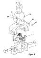
- FIG. 3 differs from the base element 1 in that it is suitable for a so-called keyhole rail 23.2.
- This keyhole rail is characterized by spaced keyhole-like recess 10, wherein the base member 1.1 has at least two clamping feet 4.4 and 4.5, which are inserted into the larger part of the keyhole recess 10. By axial displacement then engage these clamping feet 4.4 and 4.5 the narrower area of the keyhole.
- a corresponding locking element 5.2 for insertion into the main body 8 of the retainer 2 then also has only two Riegelhesschen 6.5 and 6.6, which engage in locking position in a correspondingly shaped part 26 of the keyhole, in which the clamping foot 4.5 has been used.
- a connecting element 3.1 is formed like a bridge and has an upstanding bolt 19, to which an arbitrary element for fixing the cargo may be arranged. It is also conceivable that a portion of the cargo has a blind hole into which the bolt 19 fits.
- the connecting element 3.2 has a gimbal head 20, which is rotatable relative to a bridge element 21 about a vertical axis A.
- a fork-shaped hat 22 is rotatable about a horizontal axis B.
- a kit of base elements 1, 1.1, retainer 2 of base body 8 with different locking elements 5.1 and 5.2 and connecting elements 3, 3.1 and 3.2 are formed.
- the basic elements 1, 1.1 are selected. If an airline rail 23.1 is present or provided in the hold, the base elements 1 are selected. If, on the other hand, a keyhole rail 23.2 is present or provided, the base element 1.1 is selected.
- the locking element 5.1 or 5.2 in which case the main body 8 of the retainer is the same.
- This main body 8 has a latching or snap-in device, in which, depending on the requirement, the locking element 5.1 or the locking element 5.2 can be used.
- the retainer 2 with the respective locking element 5.1 or 5.2 is now inserted into the base element 1 or 1.1 and can be moved vertically relative to the base element 1 or 1.1.
- the coil spring 7 is inserted into the retainer 2 and is supported downward against the locking element 5.1 or 5.2 from.
- connection element 3 3.1 or 3.2 is selected.
- connecting element 3 and the addition of the abutment 11 is carried out to support against the coil spring 7.
- the other connecting elements 3.1 and 3.2 are supported against the coil spring 7 itself.
- the connecting elements 3, 3.1 and 3.2 are placed on the base element 1 or 1.1 such that they engage in each case between two lugs 12.1 and 12.2 or 12.3, 12.4 and congruate the corresponding passages 14.1 and 14.2 with the openings 13.1 to 13.4. Thereafter, the pins 15.1 and 15.2 are pushed through the openings and the passages and connect the connecting elements 3, 3.1, 3.2 with the base elements 1, 1.1. Finally, the labels 17.1 and 17.2 can then be inserted into the pins 15.1 and 15.2.
Landscapes
- Engineering & Computer Science (AREA)
- Transportation (AREA)
- Mechanical Engineering (AREA)
- Connection Of Plates (AREA)
- Fittings On The Vehicle Exterior For Carrying Loads, And Devices For Holding Or Mounting Articles (AREA)
- Clamps And Clips (AREA)
Abstract
Description
Die Erfindung betrifft ein Verfahren zum Herstellen und/oder Umbauen einer Befestigungseinrichtung zum Festlegen von Ladegut in einem Frachtraum entsprechend dem Oberbegriff von Anspruch 1, sowie einen Bausatz zur Durchführung dieses Verfahrens und entsprechende Befestigungseinrichtungen.The invention relates to a method for producing and / or converting a fastening device for fixing cargo in a cargo hold according to the preamble of
Derartige Befestigungseinrichtungen sind in vielfältiger Form und Ausführung bekannt und auf dem Markt. Nur beispielsweise wird auf die
Ein ähnlicher Gleitkörper, der entlang einer Schiene geführt ist und in dem ein Bolzen zum Einfahren in eine Schienenausnehmung integriert ist, der unter dem Druck einer Feder in Rastlage gehalten wird, ist beispielsweise aus der
Auch aus der
Aufgabe der vorliegenden Erfindung ist es, ein Verfahren, einen Bausatz zur Durchführung dieses Verfahrens und entsprechende Befestigungseinrichtungen anzubieten, die äusserst vielseitig anwendbar sind und mit einem Minimum an Einzelteilen ein Maximum an Funktionen und Produkten erzielen, wodurch Kosten in erheblichem Masse gesenkt werden können.The object of the present invention is to provide a method, a kit for carrying out this method and corresponding fastening devices, which are extremely versatile and with a minimum of individual parts a maximum of functions and Products, which can significantly reduce costs.
Zur Lösung der Aufgabe führen die Merkmale der Ansprüche 1, 8, 9, 10, 14 und/oder 16.To achieve the object, the features of
Grundgedanke der vorliegenden Erfindung ist es, Befestigungseinrichtungen der o.g. Art zu schaffen, die aus möglichst wenigen einzelnen unterschiedlichen Elementen zusammengestellt sind, jedoch unterschiedlichen Anforderungen Rechnung tragen können. Je nach diesen unterschiedlichen Anforderungen können die Befestigungseinrichtungen zusammengebaut und dem Kunden zur Verfügung gestellt werden. Die Anforderungen gehen zum einen von den Schienen selbst aus. Das bedeutet, dass die Basiselemente diesen Schienen angepasst sein müssen. Bei der heutigen Befestigungstechnik vor allem in Frachträumen von Fahrzeugen werden beispielsweise sogenannte Airline-Schienen oder Schlüsselloch-Schienen verwendet. Je nach deren Ausgestaltung ist auch das Basiselement ausgebildet.The basic idea of the present invention is to provide fastening devices of the above mentioned type. To create a kind of collection that is composed of as few individual elements as possible, but can accommodate different requirements. Depending on these different requirements, the fastening devices can be assembled and made available to the customer. The requirements are based on the rails themselves. This means that the base elements must be adapted to these rails. In today's fastening technology, especially in the cargo holds of vehicles, for example so-called airline rails or keyhole rails are used. Depending on their design, the base element is formed.
Aber auch die Retainer richten sich nach diesen Schienen. Ein Retainer, der dem Festlegen des Basiselementes in einer Airline-Schiene dient, hat eine andere Ausgestaltung, als ein Retainer für beispielsweise eine Schlüsselloch-Schiene. Hier soll allerdings vom Erfindungsgedanken umfasst sein, dass der Retainer aus einem immer gleichbleibenden Grundkörper besteht, in den nur ein unterschiedliches Riegelelement eingesetzt wird, je nach dem, ob die Befestigungseinrichtung für eine Airline-Schiene oder für eine Schlüsselloch-Schiene geeignet ist.But the retainers also follow these rails. A retainer, which serves to fix the base element in an airline rail, has a different configuration than a retainer for, for example, a keyhole rail. Here, however, should be encompassed by the inventive idea that the retainer consists of an always constant body in which only a different locking element is used, depending on whether the attachment device is suitable for an airline rail or for a keyhole rail.
Der Retainer dient dazu, das Basiselement gegenüber der Schiene festzulegen. Aus diesem Grunde ist der Retainer in der Regel gegenüber dem Basiselement vertikal verschiebbar ausgebildet. In Riegelstellung fährt er mit entsprechenden Riegelfüsschen in Ausnehmungen der Schiene ein, allerdings soll er dann auch wieder vertikal anhebbar ausgestaltet sein, damit diese Riegelstellung gelöst werden kann. Das Ganze geschieht bevorzugt gegen die Kraft eines Kraftspeichers, beispielsweise gegen die Kraft einer Schraubenfeder.The retainer serves to fix the base element in relation to the rail. For this reason, the retainer is usually formed vertically displaceable relative to the base member. In lock position, he drives with corresponding Riegelfüsschen in recesses of the rail, however, it should then also be designed to be liftable vertically again, so that this locking position can be solved. The whole thing is preferably done against the force of an energy storage device, for example against the force of a coil spring.
Wiederum verschiedene Ausgestaltungen können die Verbindungselemente erfordern. Es gibt Verbindungselemente, an denen beispielsweise ein Zurrgurt festgelegt werden soll. In diesem Fall ist das Verbindungselement als Bügel ausgestaltet. Andere Verbindungselemente sollen einen Bolzen besitzen, der in ein Sackloch in dem Ladegut eingesetzt werden soll. Andere Verbindungselemente sind balkenschuhartig, beispielsweise für Sperrbalken ausgebildet. Hier sind sehr viele Möglichkeiten denkbar, die von der vorliegenden Erfindung umfasst sein sollen.Again, various configurations may require the fasteners. There are fasteners on which, for example, a lashing strap is to be determined. In this case, the connecting element is designed as a bracket. Other fasteners should have a bolt to be inserted into a blind hole in the load. Other connecting elements are bar shoe-like, formed for example for locking bar. Here are many possibilities conceivable, which should be encompassed by the present invention.
Erfindungsgemäss ist aber allen Verbindungselementen gemeinsam, dass sie bevorzugt durch einen Stift mit dem Basiselement verbunden werden. Hierzu greift das Verbindungselement zwischen zwei Laschen des Basiselementes ein, wobei ein Durchlass des Verbindungselementes mit jeweils einer Öffnung in der Lasche kongruiert. Durch diese beiden Öffnungen und den Durchlass im Verbindungselement kann ein Stift gesteckt werden.According to the invention, however, all connecting elements have in common that they are preferably connected by a pin to the base element. For this purpose, the connecting element engages between two tabs of the base element, wherein a passage of the connecting element congruent with one opening in the tab. Through these two openings and the passage in the connecting element, a pin can be inserted.
Bevorzugt ist der Stift als Spannstift ausgelegt. Hierzu besitzt er beispielsweise einen Längsschlitz, wodurch ein Durchmesser des Stiftes verringert werden kann. Sitzt der Stift dann in Riegellage, spreizt er sich wieder auf, wodurch ein Klappern von Verbindungselement gegenüber Basiselement vermieden wird.Preferably, the pin is designed as a dowel pin. For this purpose, for example, he has a longitudinal slot, whereby a diameter of the pin can be reduced. If the pin then sits in the locked position, it expands again, which avoids clattering of the connecting element relative to the base element.
Des weiteren soll dieser Stift endwärtig eine Öffnung zur Aufnahme einer Kennzeichnung aufweisen. Dies kann beispielsweise ein Firmenlogo einer bestimmten Firma, insbesondere der Firma, die die Befestigungseinrichtung verwendet, sein.Furthermore, this pin should endwärtig have an opening for receiving a label. This may be, for example, a company logo of a particular company, in particular the company using the fastening device.
Denkbar ist natürlich auch, dass der Stift als Schnellverschluss ausgebildet ist. Beispielsweise kann der Stift als Inbus ausgebildet sein und einen bestimmten Querschnitt aufweisen, der mit einem dazu passenden Querschnitt der Durchlässe zusammenwirkt, so dass eine Verspannung stattfindet. Hier sind viele Möglichkeiten denkbar und sollen von der vorliegenden Erfindung umfasst sein.It is also conceivable, of course, that the pin is designed as a quick release. For example, the pin may be formed as an Allen and have a certain cross section, which cooperates with a matching cross section of the passages, so that a tension takes place. Many possibilities are conceivable here and should be covered by the present invention.
Von der Erfindung umfasst ist auch ein Bausatz aus den verschiedenen o.g. Elementen zur Durchführung des Verfahrens. Dieser Bausatz besitzt eine Mehrzahl von unterschiedlichen Basiselementen und Retainern, welche für unterschiedliche Schienen vorgesehen sind, sowie eine Mehrzahl von unterschiedlichen Verbindungselementen für unterschiedliche Ladegüter.Also included in the invention is a kit of the various o.g. Elements for carrying out the method. This kit has a plurality of different base elements and retainers, which are provided for different rails, as well as a plurality of different connecting elements for different loads.
Desgleichen soll von dem Erfindungsgedanken auch eine Befestigungseinrichtung umfasst sein, die nach dem erfindungsgemässen Verfahren hergestellt wurde.Likewise, the inventive concept also includes a fastening device that has been produced by the method according to the invention.
Speziell Schutz begehrt wird für eine Befestigungseinrichtung, bei der das Verbindungselement auf die oben beschriebene Art und Weise mit dem Basiselement verbunden ist, d.h., bei der das Basiselement zumindest zwei, bevorzugt vier kongruierende Öffnungen aufweist und das Verbindungselement zwischen die zumindest zwei, bevorzugt vier Öffnungen eingreift und einen die Öffnungen verbindenden Durchlass aufweist, wobei ein Stift durch die Öffnungen und den Durchlass eingesetzt ist.Specifically, protection is desired for a fastening device in which the connecting element is connected to the base element in the manner described above, ie in which the base element has at least two, preferably four congruent openings and the connecting element between the at least two, preferably four openings engages and has a passage connecting the openings, wherein a pin is inserted through the openings and the passage.
Ferner wird separat Schutz auch für eine Befestigungseinrichtung begehrt, bei der der Retainer einen Grundkörper aufweist, in den ein Einsatz mit Riegelelementen eingesetzt ist. Dies hat nämlich den weiteren Vorteil, dass hier der Grundkörper aus Kunststoff hergestellt sein kann, da er ausser der Führung des Riegelelementes keine weitere Aufgabe hat. Zumindest ist er keinen Belastungen ausgesetzt. Die übrigen Teile der Befestigungseinrichtung, mit Ausnahme des Widerlagers, werden dagegen aus Festigkeitsgründen aus Metall geformt, insbesondere gegossen. Dies gilt für Basiselement, Riegelelement und Verbindungselement.Furthermore, protection is sought separately for a fastening device in which the retainer has a basic body into which an insert with locking elements is inserted. This has the further advantage that here the base body can be made of plastic, since he has no further task except the leadership of the locking element. At least he is not exposed to stress. The remaining parts of the fastening device, with the exception of the abutment, however, for reasons of strength Metal shaped, in particular cast. This applies to base element, locking element and connecting element.
Separat Schutz begehrt wird ferner auch für eine Befestigungseinrichtung, bei der das Verbindungselement einen kardanisch bewegbaren Kopf aufweist. Hier besteht das Verbindungselement aus einem Brückenelement, von dem ein Drehstück aufragt, das gegenüber dem Brückenelement drehbar ist. Diesem Drehstück sitzt dann wiederum ein gabelförmiger Hut auf, der um eine waagrechte Achse gegenüber dem Drehstück drehbar ist.Separate protection is also desired for a fastening device in which the connecting element has a gimbal-like movable head. Here, the connecting element consists of a bridge element, from which a rotary piece rises, which is rotatable relative to the bridge element. This turntable then sits in turn a fork-shaped hat, which is rotatable about a horizontal axis relative to the rotating piece.
Weitere Vorteile, Merkmale und Einzelheiten der Erfindung ergeben sich aus der nachfolgenden Beschreibung bevorzugter Ausführungsbeispiele sowie anhand der Zeichnung; diese zeigt in
-
Figur 1 -
Figur 2 bis 5
-
FIG. 1 a perspective view of a fastening device according to the invention for determining cargo in a cargo hold in an exploded view; -
FIGS. 2 to 5 perspective views of other fasteners for fixing cargo in a cargo hold or parts thereof in exploded view.
Eine erfindungsgemässe Befestigungseinrichtung P1 zum Festlegen von Ladegut in einem Frachtraum weist ein Basiselement 1 zum Einsetzen in eine in
Gemäss der vorliegenden Erfindung ist dabei das Riegelelement 5.1 in einen Grundkörper 8 des Retainers 2 eingesetzt und der ganze Retainer 2 zusammen mit dem Riegelelement 5.1 vertikal entlang dem Basiselement 1 führbar. Hierzu kann - nicht gezeigt - ein Führungselement, z.B. ein Zapfen, eine entsprechende Führungsöffnung in dem Riegelelement 5.1 durchsetzen.According to the present invention, the locking element 5.1 is inserted into a main body 8 of the
Die Schraubenfeder 7 drückt einerseits auf das Riegelelement 5.1, andererseits stützt sie sich gegen ein Widerlager 11 ab, welches zusammen mit dem Verbindungselement 3 an dem Basiselement 1 festgelegt wird. Zu diesem Zweck ragen von dem Basiselement 1 vier Laschen 12.1 bis 12.4 auf, die jeweils eine Öffnung 13.1 bis 13.4 besitzen. Ebenso besitzt das Verbindungselement 3 bzw. ein bügelartiger Körper 18 in seinen Endbereichen jeweils einen Durchlass 14.1 und 14.2, welche in Gebrauchslage zwischen jeweils zwei Laschen 12.1, 12.2 bzw. 12.3, 12.4 angeordnet sind und mit den Öffnungen 13.1, 13.2 bzw. 13.3, 13.4 kongruieren. Gesichert wird dabei das Verbindungselement 3 mittels Stiften 15.1 und 15.2, welche durch die Öffnung 13.1, den Durchlass 14.1 und die Öffnung 13.2 sowie eine Öffnung 13.4, 14.2, und 13.3 eingesetzt werden. Diese Stifte sind als Spannstifte ausgebildet. Hierzu weisen sie beispielsweise einen nicht näher gezeigten Längsschlitz auf, wodurch beim Einsetzen der Stifte 15.1 bzw. 15.2 deren Durchmesser verringert werden kann, während sie sich dann in Gebrauchslage aber aufspreizen und so in den Öffnungen bzw. Durchlässen verspannen.The
Diesen Stiften 15.1 bzw. 15.2 kann endwärtig eine Kennzeichnung 17.1 bzw. 17.2 zugeordnet werden, was der Einfachheit halber dadurch geschieht, dass entsprechende Fortsätze an den Kennzeichnungen 17.1 bzw. 17.2 in die vordere Öffnung der hülsenförmigen Stifte 15.1 bzw.15.2 eingeschoben werden. In die jeweils hintere Öffnung der Stifte 15.1 bzw. 15.2 kann dann ein Zapfen 9 des Widerlagers 11 eingesetzt werden, wodurch dieses ebenfalls gegenüber dem Basiselemente 1 festgelegt wird. In
Ein weiteres Basiselement 1.1 gemäss
Ein entsprechendes Riegelelement 5.2 zum Einsetzen in den Grundkörper 8 des Retainers 2 besitzt dann auch nur zwei Riegelfüsschen 6.5 und 6.6, die in Riegellage in einen entsprechend geformten Teil 26 des Schlüssellochs eingreifen, in den der Klemmfuss 4.5 eingesetzt wurde.A corresponding locking element 5.2 for insertion into the main body 8 of the
In
Das Verbindungselement 3.2 gemäss
Die Funktionsweise der vorliegenden Erfindung ist folgende:The operation of the present invention is as follows:
Für Befestigungseinrichtungen P1 bis P3 wird ein Bausatz aus Basiselementen 1, 1.1, Retainer 2 aus Grundkörper 8 mit unterschiedlichen Riegelelementen 5.1 und 5.2 sowie Verbindungselementen 3, 3.1 und 3.2 gebildet. Je nach Wunsch des Kunden bzw. Anforderungen der Frachträume werden die Basiselemente 1, 1.1 ausgesucht. Ist im Frachtraum eine Airline-Schiene 23.1 vorhanden oder vorgesehen, so werden die Basiselemente 1 ausgesucht. Ist dagegen eine Schlüsselloch-Schiene 23.2 vorhanden oder vorgesehen, wird das Basiselement 1.1 gewählt. Das gleiche gilt auch für das Riegelelement 5.1 bzw. 5.2, wobei hier der Grundkörper 8 des Retainers der gleiche ist. Dieser Grundkörper 8 besitzt eine Rast- oder Schnappeinrichtung, in die je nach Anforderung das Riegelelement 5.1 oder das Riegelelement 5.2 eingesetzt werden kann.For fastening devices P1 to P3 is a kit of
Der Retainer 2 mit dem jeweiligen Riegelelement 5.1 oder 5.2 wird nun in das Basiselement 1 bzw. 1.1 eingesetzt und kann vertikal gegenüber dem Basiselement 1 bzw. 1.1 bewegt werden.The
Anschliessend wird die Schraubenfeder 7 in den Retainer 2 eingesetzt und stützt sich nach unten gegen das Riegelelement 5.1 bzw. 5.2 ab.Subsequently, the
Nunmehr wird ein gewünschtes Verbindungselement 3, 3.1 bzw. 3.2 ausgewählt. Beim Verbindungselement 3 erfolgt auch der Zusatz des Widerlagers 11 zum Abstützen gegenüber der Schraubenfeder 7. Die anderen Verbindungselemente 3.1 und 3.2 stützen sich selbst gegen die Schraubenfeder 7 ab.Now, a desired
Die Verbindungselemente 3, 3.1 und 3.2 werden so auf das Basiselement 1 bzw. 1.1 aufgesetzt, dass sie jeweils zwischen zwei Laschen 12.1 und 12.2 bzw. 12.3, 12.4 eingreifen und die entsprechenden Durchlässe 14.1 und 14.2 mit den Öffnungen 13.1 bis 13.4 kongruieren. Danach werden die Stifte 15.1 und 15.2 durch die Öffnungen und die Durchlässe hindurchgeschoben und verbinden so die Verbindungselemente 3, 3.1, 3.2 mit den Basiselementen 1, 1.1. Zum Schluss können dann die Kennzeichnungen 17.1 bzw. 17.2 in die Stifte 15.1 bzw. 15.2 eingesetzt werden.The connecting
Claims (16)
gekennzeichnet durch
marked by
Applications Claiming Priority (1)
| Application Number | Priority Date | Filing Date | Title |
|---|---|---|---|
| DE201110056722 DE102011056722A1 (en) | 2011-12-20 | 2011-12-20 | Method for producing and / or converting a fastening device for securing cargo in a cargo hold |
Publications (3)
| Publication Number | Publication Date |
|---|---|
| EP2607162A2 true EP2607162A2 (en) | 2013-06-26 |
| EP2607162A3 EP2607162A3 (en) | 2018-02-21 |
| EP2607162B1 EP2607162B1 (en) | 2019-07-17 |
Family
ID=47504706
Family Applications (1)
| Application Number | Title | Priority Date | Filing Date |
|---|---|---|---|
| EP12198100.5A Active EP2607162B1 (en) | 2011-12-20 | 2012-12-19 | Method for producing and/or converting a fixing device for fixing cargo in a cargo space |
Country Status (2)
| Country | Link |
|---|---|
| EP (1) | EP2607162B1 (en) |
| DE (1) | DE102011056722A1 (en) |
Cited By (3)
| Publication number | Priority date | Publication date | Assignee | Title |
|---|---|---|---|---|
| FR3065190A1 (en) * | 2017-04-18 | 2018-10-19 | Pommier | ARRIMAGE RING ARRANGEMENT ON A SUPPORT STRUCTURE SUCH AS THE EDGE OF A BANK OR A FLOOR IN PARTICULAR OF LOADING A TRANSPORT VEHICLE |
| WO2022020703A1 (en) * | 2020-07-24 | 2022-01-27 | Polaris Industries Inc. | Article mounting system for a vehicle |
| DE102022114784B3 (en) | 2022-06-13 | 2023-07-20 | allsafe GmbH & Co.KG | Fitting and system comprising a fitting and a rail |
Citations (4)
| Publication number | Priority date | Publication date | Assignee | Title |
|---|---|---|---|---|
| DE10036553A1 (en) | 2000-03-03 | 2001-09-13 | Ancra Jungfalk Gmbh & Co Kg | Car seat anchorage of floor rail and slide uses slide of end hinged elements to permit slide movement even in torqued rail assisted by seat-fitted holder engaging floor rail holes. |
| DE20306549U1 (en) | 2003-04-25 | 2003-07-17 | Ancra Jungfalk Gmbh & Co Kg | System for fastening of load in load holding space has parking mounting provided on wall or wall fitting of load space and is height adjustable and movably installed on rail |
| DE102005001202A1 (en) | 2004-01-12 | 2005-08-04 | Allsafe Jungfalk Gmbh & Co. Kg | Device for temporarily connecting object to rail profile has intermediate element that can be inserted into adjacent bores in profile so shaped mounting surface protrudes over surface of profile, collar element engages under groove edges |
| EP1794053A1 (en) | 2004-09-28 | 2007-06-13 | allsafe Jungfalk GmbH & Co. KG | Device for fixing an object to a rail |
Family Cites Families (3)
| Publication number | Priority date | Publication date | Assignee | Title |
|---|---|---|---|---|
| US7980798B1 (en) * | 2007-06-18 | 2011-07-19 | Adac Plastics, Inc. | Tie-down assembly |
| GB2466801A (en) * | 2009-01-07 | 2010-07-14 | Unwin C N Ltd | Anchorage system for fixing articles to vehicle floor rail |
| FR2943986A1 (en) * | 2009-04-06 | 2010-10-08 | Antar Daouk | COUPLING DEVICE WITH LONGITUDINAL DISPLACEMENT FACULTY |
-
2011
- 2011-12-20 DE DE201110056722 patent/DE102011056722A1/en not_active Withdrawn
-
2012
- 2012-12-19 EP EP12198100.5A patent/EP2607162B1/en active Active
Patent Citations (4)
| Publication number | Priority date | Publication date | Assignee | Title |
|---|---|---|---|---|
| DE10036553A1 (en) | 2000-03-03 | 2001-09-13 | Ancra Jungfalk Gmbh & Co Kg | Car seat anchorage of floor rail and slide uses slide of end hinged elements to permit slide movement even in torqued rail assisted by seat-fitted holder engaging floor rail holes. |
| DE20306549U1 (en) | 2003-04-25 | 2003-07-17 | Ancra Jungfalk Gmbh & Co Kg | System for fastening of load in load holding space has parking mounting provided on wall or wall fitting of load space and is height adjustable and movably installed on rail |
| DE102005001202A1 (en) | 2004-01-12 | 2005-08-04 | Allsafe Jungfalk Gmbh & Co. Kg | Device for temporarily connecting object to rail profile has intermediate element that can be inserted into adjacent bores in profile so shaped mounting surface protrudes over surface of profile, collar element engages under groove edges |
| EP1794053A1 (en) | 2004-09-28 | 2007-06-13 | allsafe Jungfalk GmbH & Co. KG | Device for fixing an object to a rail |
Cited By (5)
| Publication number | Priority date | Publication date | Assignee | Title |
|---|---|---|---|---|
| FR3065190A1 (en) * | 2017-04-18 | 2018-10-19 | Pommier | ARRIMAGE RING ARRANGEMENT ON A SUPPORT STRUCTURE SUCH AS THE EDGE OF A BANK OR A FLOOR IN PARTICULAR OF LOADING A TRANSPORT VEHICLE |
| EP3392086A1 (en) * | 2017-04-18 | 2018-10-24 | Pommier | Arrangement of a securing ring on a supporting structure such as the bank edge or a floor, in particular for loading a transport vehicle |
| WO2022020703A1 (en) * | 2020-07-24 | 2022-01-27 | Polaris Industries Inc. | Article mounting system for a vehicle |
| US11511678B2 (en) | 2020-07-24 | 2022-11-29 | Polaris Industries Inc. | Article mounting system for a vehicle |
| DE102022114784B3 (en) | 2022-06-13 | 2023-07-20 | allsafe GmbH & Co.KG | Fitting and system comprising a fitting and a rail |
Also Published As
| Publication number | Publication date |
|---|---|
| EP2607162B1 (en) | 2019-07-17 |
| DE102011056722A1 (en) | 2013-06-20 |
| EP2607162A3 (en) | 2018-02-21 |
Similar Documents
| Publication | Publication Date | Title |
|---|---|---|
| DE102011079334A1 (en) | Charging rail and sliding block for a charging rail | |
| DE202006007845U1 (en) | Mounting system for armor or ballast plates in helicopters comprises plate with rail on its underside which fits into slot in base plate | |
| DE19939655C1 (en) | Automobile window operating device has ball-and-socket couplings for securing guide rail for window panel to base component, e.g. inside door panel | |
| DE102011009211A1 (en) | Clip device for fastening seat shell to seat frame of vehicle seat for motor vehicle, particularly for sliding or rotary mounting, is provided with clip units, where connecting element is provided for connecting two clip units | |
| EP2607162B1 (en) | Method for producing and/or converting a fixing device for fixing cargo in a cargo space | |
| EP1989455B1 (en) | Guide rail comprising a cover strip for a linear bearing | |
| EP2199473A1 (en) | Toilet body with wall mount | |
| DE202011100696U1 (en) | Tolerance compensation device | |
| DE102016204483A1 (en) | Fastening element with at least one clip for producing a connection with a corresponding Ansteckelement and arrangement of a fastener on a Ansteckelement | |
| EP3773074B1 (en) | Drawer system with pull-out rail onto which different drawers can be installed | |
| DE102007012656A1 (en) | Fastening device for motor vehicle, has hook and-loop fastener pad attached to disc-shaped head, and base having elastic characteristics designed in three-quarter circular manner, where head exerts tension on lining | |
| DE102009034584A1 (en) | Fitting for fastening device of clip-like connection in seat belt system in vehicle, has vehicle-sided fastening bolt, and belt strap deflection element connected with fitting, where fitting is fastened at vehicle side via fastening bolt | |
| DE102013102247A1 (en) | Approach for connecting a rail to an element of a cargo hold | |
| DE102013107083B4 (en) | Device for fixing an object | |
| DE102007024658A1 (en) | Device and method for fastening, clamping or adjusting two components to each other | |
| EP1693252A1 (en) | Mounting mechanism | |
| DE102005040640B4 (en) | Guide rail for the deflection fitting of a safety belt for motor vehicles | |
| EP2803533B1 (en) | Device for assembling a rail on a support with a longitudinal channel | |
| DE202018005759U1 (en) | Freight transport system with a sandwich panel and a port | |
| EP2592967B1 (en) | Opening and/or closing device and mounting process | |
| DE102022001433A1 (en) | Multiple tool for screwing screw elements | |
| EP4119754A1 (en) | Mounting plate assembly and door frame assembly | |
| DE10012771B4 (en) | Gun lock for break-barrel gun, has impact spring, which is stretched by manually operated drive and locking lever, which is pivot-mounted at gun lock housing | |
| DE2205452A1 (en) | COUPLING FOR VEHICLES OF PLAY AND MODEL TRACKS | |
| DE102018130951A1 (en) | Modular device for mounting a radiator and mounting kit for this |
Legal Events
| Date | Code | Title | Description |
|---|---|---|---|
| AK | Designated contracting states |
Kind code of ref document: A2 Designated state(s): AL AT BE BG CH CY CZ DE DK EE ES FI FR GB GR HR HU IE IS IT LI LT LU LV MC MK MT NL NO PL PT RO RS SE SI SK SM TR |
|
| AX | Request for extension of the european patent |
Extension state: BA ME |
|
| PUAI | Public reference made under article 153(3) epc to a published international application that has entered the european phase |
Free format text: ORIGINAL CODE: 0009012 |
|
| RAP1 | Party data changed (applicant data changed or rights of an application transferred) |
Owner name: ALLSAFE GMBH & CO. KG |
|
| PUAL | Search report despatched |
Free format text: ORIGINAL CODE: 0009013 |
|
| AK | Designated contracting states |
Kind code of ref document: A3 Designated state(s): AL AT BE BG CH CY CZ DE DK EE ES FI FR GB GR HR HU IE IS IT LI LT LU LV MC MK MT NL NO PL PT RO RS SE SI SK SM TR |
|
| AX | Request for extension of the european patent |
Extension state: BA ME |
|
| RIC1 | Information provided on ipc code assigned before grant |
Ipc: B60P 7/08 20060101AFI20180118BHEP |
|
| STAA | Information on the status of an ep patent application or granted ep patent |
Free format text: STATUS: REQUEST FOR EXAMINATION WAS MADE |
|
| 17P | Request for examination filed |
Effective date: 20180718 |
|
| RBV | Designated contracting states (corrected) |
Designated state(s): AL AT BE BG CH CY CZ DE DK EE ES FI FR GB GR HR HU IE IS IT LI LT LU LV MC MK MT NL NO PL PT RO RS SE SI SK SM TR |
|
| GRAP | Despatch of communication of intention to grant a patent |
Free format text: ORIGINAL CODE: EPIDOSNIGR1 |
|
| STAA | Information on the status of an ep patent application or granted ep patent |
Free format text: STATUS: GRANT OF PATENT IS INTENDED |
|
| INTG | Intention to grant announced |
Effective date: 20190129 |
|
| GRAS | Grant fee paid |
Free format text: ORIGINAL CODE: EPIDOSNIGR3 |
|
| GRAA | (expected) grant |
Free format text: ORIGINAL CODE: 0009210 |
|
| STAA | Information on the status of an ep patent application or granted ep patent |
Free format text: STATUS: THE PATENT HAS BEEN GRANTED |
|
| AK | Designated contracting states |
Kind code of ref document: B1 Designated state(s): AL AT BE BG CH CY CZ DE DK EE ES FI FR GB GR HR HU IE IS IT LI LT LU LV MC MK MT NL NO PL PT RO RS SE SI SK SM TR |
|
| REG | Reference to a national code |
Ref country code: GB Ref legal event code: FG4D Free format text: NOT ENGLISH |
|
| REG | Reference to a national code |
Ref country code: CH Ref legal event code: EP |
|
| REG | Reference to a national code |
Ref country code: IE Ref legal event code: FG4D Free format text: LANGUAGE OF EP DOCUMENT: GERMAN |
|
| REG | Reference to a national code |
Ref country code: DE Ref legal event code: R096 Ref document number: 502012015033 Country of ref document: DE |
|
| REG | Reference to a national code |
Ref country code: AT Ref legal event code: REF Ref document number: 1155548 Country of ref document: AT Kind code of ref document: T Effective date: 20190815 |
|
| REG | Reference to a national code |
Ref country code: SE Ref legal event code: TRGR |
|
| REG | Reference to a national code |
Ref country code: NL Ref legal event code: FP |
|
| REG | Reference to a national code |
Ref country code: LT Ref legal event code: MG4D |
|
| PG25 | Lapsed in a contracting state [announced via postgrant information from national office to epo] |
Ref country code: FI Free format text: LAPSE BECAUSE OF FAILURE TO SUBMIT A TRANSLATION OF THE DESCRIPTION OR TO PAY THE FEE WITHIN THE PRESCRIBED TIME-LIMIT Effective date: 20190717 Ref country code: PT Free format text: LAPSE BECAUSE OF FAILURE TO SUBMIT A TRANSLATION OF THE DESCRIPTION OR TO PAY THE FEE WITHIN THE PRESCRIBED TIME-LIMIT Effective date: 20191118 Ref country code: HR Free format text: LAPSE BECAUSE OF FAILURE TO SUBMIT A TRANSLATION OF THE DESCRIPTION OR TO PAY THE FEE WITHIN THE PRESCRIBED TIME-LIMIT Effective date: 20190717 Ref country code: LT Free format text: LAPSE BECAUSE OF FAILURE TO SUBMIT A TRANSLATION OF THE DESCRIPTION OR TO PAY THE FEE WITHIN THE PRESCRIBED TIME-LIMIT Effective date: 20190717 Ref country code: BG Free format text: LAPSE BECAUSE OF FAILURE TO SUBMIT A TRANSLATION OF THE DESCRIPTION OR TO PAY THE FEE WITHIN THE PRESCRIBED TIME-LIMIT Effective date: 20191017 Ref country code: NO Free format text: LAPSE BECAUSE OF FAILURE TO SUBMIT A TRANSLATION OF THE DESCRIPTION OR TO PAY THE FEE WITHIN THE PRESCRIBED TIME-LIMIT Effective date: 20191017 |
|
| PG25 | Lapsed in a contracting state [announced via postgrant information from national office to epo] |
Ref country code: IS Free format text: LAPSE BECAUSE OF FAILURE TO SUBMIT A TRANSLATION OF THE DESCRIPTION OR TO PAY THE FEE WITHIN THE PRESCRIBED TIME-LIMIT Effective date: 20191117 Ref country code: AL Free format text: LAPSE BECAUSE OF FAILURE TO SUBMIT A TRANSLATION OF THE DESCRIPTION OR TO PAY THE FEE WITHIN THE PRESCRIBED TIME-LIMIT Effective date: 20190717 Ref country code: ES Free format text: LAPSE BECAUSE OF FAILURE TO SUBMIT A TRANSLATION OF THE DESCRIPTION OR TO PAY THE FEE WITHIN THE PRESCRIBED TIME-LIMIT Effective date: 20190717 Ref country code: GR Free format text: LAPSE BECAUSE OF FAILURE TO SUBMIT A TRANSLATION OF THE DESCRIPTION OR TO PAY THE FEE WITHIN THE PRESCRIBED TIME-LIMIT Effective date: 20191018 Ref country code: LV Free format text: LAPSE BECAUSE OF FAILURE TO SUBMIT A TRANSLATION OF THE DESCRIPTION OR TO PAY THE FEE WITHIN THE PRESCRIBED TIME-LIMIT Effective date: 20190717 Ref country code: RS Free format text: LAPSE BECAUSE OF FAILURE TO SUBMIT A TRANSLATION OF THE DESCRIPTION OR TO PAY THE FEE WITHIN THE PRESCRIBED TIME-LIMIT Effective date: 20190717 |
|
| PG25 | Lapsed in a contracting state [announced via postgrant information from national office to epo] |
Ref country code: TR Free format text: LAPSE BECAUSE OF FAILURE TO SUBMIT A TRANSLATION OF THE DESCRIPTION OR TO PAY THE FEE WITHIN THE PRESCRIBED TIME-LIMIT Effective date: 20190717 |
|
| PG25 | Lapsed in a contracting state [announced via postgrant information from national office to epo] |
Ref country code: EE Free format text: LAPSE BECAUSE OF FAILURE TO SUBMIT A TRANSLATION OF THE DESCRIPTION OR TO PAY THE FEE WITHIN THE PRESCRIBED TIME-LIMIT Effective date: 20190717 Ref country code: PL Free format text: LAPSE BECAUSE OF FAILURE TO SUBMIT A TRANSLATION OF THE DESCRIPTION OR TO PAY THE FEE WITHIN THE PRESCRIBED TIME-LIMIT Effective date: 20190717 Ref country code: DK Free format text: LAPSE BECAUSE OF FAILURE TO SUBMIT A TRANSLATION OF THE DESCRIPTION OR TO PAY THE FEE WITHIN THE PRESCRIBED TIME-LIMIT Effective date: 20190717 Ref country code: RO Free format text: LAPSE BECAUSE OF FAILURE TO SUBMIT A TRANSLATION OF THE DESCRIPTION OR TO PAY THE FEE WITHIN THE PRESCRIBED TIME-LIMIT Effective date: 20190717 Ref country code: IT Free format text: LAPSE BECAUSE OF FAILURE TO SUBMIT A TRANSLATION OF THE DESCRIPTION OR TO PAY THE FEE WITHIN THE PRESCRIBED TIME-LIMIT Effective date: 20190717 |
|
| PG25 | Lapsed in a contracting state [announced via postgrant information from national office to epo] |
Ref country code: IS Free format text: LAPSE BECAUSE OF FAILURE TO SUBMIT A TRANSLATION OF THE DESCRIPTION OR TO PAY THE FEE WITHIN THE PRESCRIBED TIME-LIMIT Effective date: 20200224 Ref country code: SM Free format text: LAPSE BECAUSE OF FAILURE TO SUBMIT A TRANSLATION OF THE DESCRIPTION OR TO PAY THE FEE WITHIN THE PRESCRIBED TIME-LIMIT Effective date: 20190717 Ref country code: SK Free format text: LAPSE BECAUSE OF FAILURE TO SUBMIT A TRANSLATION OF THE DESCRIPTION OR TO PAY THE FEE WITHIN THE PRESCRIBED TIME-LIMIT Effective date: 20190717 Ref country code: CZ Free format text: LAPSE BECAUSE OF FAILURE TO SUBMIT A TRANSLATION OF THE DESCRIPTION OR TO PAY THE FEE WITHIN THE PRESCRIBED TIME-LIMIT Effective date: 20190717 |
|
| REG | Reference to a national code |
Ref country code: DE Ref legal event code: R097 Ref document number: 502012015033 Country of ref document: DE |
|
| PLBE | No opposition filed within time limit |
Free format text: ORIGINAL CODE: 0009261 |
|
| STAA | Information on the status of an ep patent application or granted ep patent |
Free format text: STATUS: NO OPPOSITION FILED WITHIN TIME LIMIT |
|
| PG2D | Information on lapse in contracting state deleted |
Ref country code: IS |
|
| REG | Reference to a national code |
Ref country code: CH Ref legal event code: PL |
|
| 26N | No opposition filed |
Effective date: 20200603 |
|
| REG | Reference to a national code |
Ref country code: BE Ref legal event code: MM Effective date: 20191231 |
|
| PG25 | Lapsed in a contracting state [announced via postgrant information from national office to epo] |
Ref country code: SI Free format text: LAPSE BECAUSE OF FAILURE TO SUBMIT A TRANSLATION OF THE DESCRIPTION OR TO PAY THE FEE WITHIN THE PRESCRIBED TIME-LIMIT Effective date: 20190717 Ref country code: MC Free format text: LAPSE BECAUSE OF FAILURE TO SUBMIT A TRANSLATION OF THE DESCRIPTION OR TO PAY THE FEE WITHIN THE PRESCRIBED TIME-LIMIT Effective date: 20190717 |
|
| GBPC | Gb: european patent ceased through non-payment of renewal fee |
Effective date: 20191219 |
|
| PG25 | Lapsed in a contracting state [announced via postgrant information from national office to epo] |
Ref country code: IE Free format text: LAPSE BECAUSE OF NON-PAYMENT OF DUE FEES Effective date: 20191219 Ref country code: LU Free format text: LAPSE BECAUSE OF NON-PAYMENT OF DUE FEES Effective date: 20191219 Ref country code: GB Free format text: LAPSE BECAUSE OF NON-PAYMENT OF DUE FEES Effective date: 20191219 |
|
| PG25 | Lapsed in a contracting state [announced via postgrant information from national office to epo] |
Ref country code: CH Free format text: LAPSE BECAUSE OF NON-PAYMENT OF DUE FEES Effective date: 20191231 Ref country code: BE Free format text: LAPSE BECAUSE OF NON-PAYMENT OF DUE FEES Effective date: 20191231 Ref country code: LI Free format text: LAPSE BECAUSE OF NON-PAYMENT OF DUE FEES Effective date: 20191231 |
|
| REG | Reference to a national code |
Ref country code: AT Ref legal event code: MM01 Ref document number: 1155548 Country of ref document: AT Kind code of ref document: T Effective date: 20191219 |
|
| PG25 | Lapsed in a contracting state [announced via postgrant information from national office to epo] |
Ref country code: CY Free format text: LAPSE BECAUSE OF FAILURE TO SUBMIT A TRANSLATION OF THE DESCRIPTION OR TO PAY THE FEE WITHIN THE PRESCRIBED TIME-LIMIT Effective date: 20190717 Ref country code: AT Free format text: LAPSE BECAUSE OF NON-PAYMENT OF DUE FEES Effective date: 20191219 |
|
| PG25 | Lapsed in a contracting state [announced via postgrant information from national office to epo] |
Ref country code: HU Free format text: LAPSE BECAUSE OF FAILURE TO SUBMIT A TRANSLATION OF THE DESCRIPTION OR TO PAY THE FEE WITHIN THE PRESCRIBED TIME-LIMIT; INVALID AB INITIO Effective date: 20121219 Ref country code: MT Free format text: LAPSE BECAUSE OF FAILURE TO SUBMIT A TRANSLATION OF THE DESCRIPTION OR TO PAY THE FEE WITHIN THE PRESCRIBED TIME-LIMIT Effective date: 20190717 |
|
| PG25 | Lapsed in a contracting state [announced via postgrant information from national office to epo] |
Ref country code: MK Free format text: LAPSE BECAUSE OF FAILURE TO SUBMIT A TRANSLATION OF THE DESCRIPTION OR TO PAY THE FEE WITHIN THE PRESCRIBED TIME-LIMIT Effective date: 20190717 |
|
| P01 | Opt-out of the competence of the unified patent court (upc) registered |
Effective date: 20230530 |
|
| PGFP | Annual fee paid to national office [announced via postgrant information from national office to epo] |
Ref country code: SE Payment date: 20231219 Year of fee payment: 12 Ref country code: NL Payment date: 20231219 Year of fee payment: 12 Ref country code: FR Payment date: 20231219 Year of fee payment: 12 |
|
| PGFP | Annual fee paid to national office [announced via postgrant information from national office to epo] |
Ref country code: DE Payment date: 20240227 Year of fee payment: 12 |