EP2607154A1 - Vehicle seat with cushion with seam area - Google Patents
Vehicle seat with cushion with seam area Download PDFInfo
- Publication number
- EP2607154A1 EP2607154A1 EP20120197436 EP12197436A EP2607154A1 EP 2607154 A1 EP2607154 A1 EP 2607154A1 EP 20120197436 EP20120197436 EP 20120197436 EP 12197436 A EP12197436 A EP 12197436A EP 2607154 A1 EP2607154 A1 EP 2607154A1
- Authority
- EP
- European Patent Office
- Prior art keywords
- upholstery
- padding
- seat
- cushion
- vehicle seat
- Prior art date
- Legal status (The legal status is an assumption and is not a legal conclusion. Google has not performed a legal analysis and makes no representation as to the accuracy of the status listed.)
- Granted
Links
- 230000004888 barrier function Effects 0.000 claims abstract description 54
- 238000007789 sealing Methods 0.000 claims description 15
- 239000000463 material Substances 0.000 claims description 9
- 238000003780 insertion Methods 0.000 claims description 6
- 230000037431 insertion Effects 0.000 claims description 6
- 238000005452 bending Methods 0.000 claims description 2
- 238000009423 ventilation Methods 0.000 description 17
- 238000004519 manufacturing process Methods 0.000 description 6
- 238000010276 construction Methods 0.000 description 5
- 239000006260 foam Substances 0.000 description 4
- 239000011541 reaction mixture Substances 0.000 description 4
- 238000005187 foaming Methods 0.000 description 3
- 238000000034 method Methods 0.000 description 3
- 239000011148 porous material Substances 0.000 description 3
- 238000005304 joining Methods 0.000 description 2
- 238000003466 welding Methods 0.000 description 2
- 240000001439 Opuntia Species 0.000 description 1
- 235000004727 Opuntia ficus indica Nutrition 0.000 description 1
- 208000002193 Pain Diseases 0.000 description 1
- 229920001247 Reticulated foam Polymers 0.000 description 1
- 239000000853 adhesive Substances 0.000 description 1
- 230000001070 adhesive effect Effects 0.000 description 1
- 230000001186 cumulative effect Effects 0.000 description 1
- 238000005553 drilling Methods 0.000 description 1
- 238000005516 engineering process Methods 0.000 description 1
- 238000009434 installation Methods 0.000 description 1
- 239000010985 leather Substances 0.000 description 1
- 238000003801 milling Methods 0.000 description 1
- 230000035515 penetration Effects 0.000 description 1
- 230000035699 permeability Effects 0.000 description 1
- 125000006850 spacer group Chemical group 0.000 description 1
Images

Classifications
-
- B—PERFORMING OPERATIONS; TRANSPORTING
- B60—VEHICLES IN GENERAL
- B60N—SEATS SPECIALLY ADAPTED FOR VEHICLES; VEHICLE PASSENGER ACCOMMODATION NOT OTHERWISE PROVIDED FOR
- B60N2/00—Seats specially adapted for vehicles; Arrangement or mounting of seats in vehicles
- B60N2/56—Heating or ventilating devices
- B60N2/5607—Heating or ventilating devices characterised by convection
- B60N2/5621—Heating or ventilating devices characterised by convection by air
-
- B—PERFORMING OPERATIONS; TRANSPORTING
- B60—VEHICLES IN GENERAL
- B60N—SEATS SPECIALLY ADAPTED FOR VEHICLES; VEHICLE PASSENGER ACCOMMODATION NOT OTHERWISE PROVIDED FOR
- B60N2/00—Seats specially adapted for vehicles; Arrangement or mounting of seats in vehicles
- B60N2/58—Seat coverings
- B60N2/5816—Seat coverings attachments thereof
- B60N2/5825—Seat coverings attachments thereof by hooks, staples, clips, snap fasteners or the like
-
- B—PERFORMING OPERATIONS; TRANSPORTING
- B60—VEHICLES IN GENERAL
- B60N—SEATS SPECIALLY ADAPTED FOR VEHICLES; VEHICLE PASSENGER ACCOMMODATION NOT OTHERWISE PROVIDED FOR
- B60N2/00—Seats specially adapted for vehicles; Arrangement or mounting of seats in vehicles
- B60N2/58—Seat coverings
- B60N2/5891—Seat coverings characterised by the manufacturing process; manufacturing seat coverings not otherwise provided for
-
- B—PERFORMING OPERATIONS; TRANSPORTING
- B60—VEHICLES IN GENERAL
- B60N—SEATS SPECIALLY ADAPTED FOR VEHICLES; VEHICLE PASSENGER ACCOMMODATION NOT OTHERWISE PROVIDED FOR
- B60N2/00—Seats specially adapted for vehicles; Arrangement or mounting of seats in vehicles
- B60N2/70—Upholstery springs ; Upholstery
- B60N2/7017—Upholstery springs ; Upholstery characterised by the manufacturing process; manufacturing upholstery or upholstery springs not otherwise provided for
Definitions
- the invention relates to a vehicle seat having a seat part, with a backrest part and with a cushion part for upholstering a seat surface of the seat part, in which the cushion part comprises a cushion covering device, a cushioning device, a barrier layer layer and a main cushioning element, and wherein the main cushioning element by the barrier layer of the Polsterbezug noise and the padding device is arranged spatially separated.
- the object of the invention is achieved by a vehicle seat with a seat part, with a backrest part and with a cushion part for cushioning a seat surface of the seat part, wherein the cushioning member comprises a padding means, a cushioning means, a barrier layer and a main padding member, and wherein the main padding member is spaced apart from the padding means and the padding means by the barrier layer, the vehicle seat being characterized in that the padding means and the padding means are arranged in Seen seat direction transversely to the seat surface and along the seat surface are designed in such a multi-part, that the cushion member radially outward two spaced apart by a Mittenaptapt lateral functional areas, wherein the lateral functional areas are each secured in a seam area at the central mirror area.
- padded part in the context of the invention describes a device by means of which the vehicle seat can be padded.
- the cushion part can be provided on the seat part and / or on the backrest part in order to make the sitting comfort more comfortable for a user of the vehicle seat.
- the present cushion part is preferably at least always provided on the seat part.
- padding core element herein describes a further functional area or a further component of the upholstery part, by which or by which a particularly good Tärteabrien on upholstery, both on the seat part and on the backrest portion of the vehicle seat, can be achieved.
- An advantageous development of the invention provides that it is advantageous if the multi-part upholstery covering a cushion cover center element and seen in the seating direction radially outside this two laterally arranged upholstery cover side elements which are firmly connected to the upholstery reference center element respectively at the seam areas, wherein the upholstery reference center element of a padding core element the cushioning device and the upholstery reference side elements each of a padding side element the padding device are supported.
- the construction of the cushion part can be further simplified considerably.
- the cushioning core element and the cushioning side elements each have a barrier layer element on their side facing away from the multi-part cushion covering device, wherein the barrier layer layer elements are connected to each other at the seam regions with sealing strip elements running along the seam regions.
- the upholstery core element is made of a relatively open-pored and thus also very good air-permeable material, whereby a particularly good breathability can be achieved at the vehicle seat, in particular in the region of the direct seat surface, ie the center mirror region of the seat part and / or the backrest part.
- the cushioning core element comprises a cut foam, a reticulated foam or a spacer knit, so that it can be structurally easily realized with good air permeability properties.
- the present cushioning core element is preferably a substantially air-permeable cushioning core element.
- the particular air-permeable padding core element is integrated in one piece and only partially in the padded part, so that the entire seat surface of the vehicle seat is not necessarily underlaid with the padding core element.
- the present cushioning core element extends in the longitudinal extent of the seat part and / or the backrest part approximately in the middle of the seat surface of the seat part and / or the backrest part.
- the padding core element also has a thickness of between 3 mm and 50 mm inclusive, preferably a thickness between and including 15mm and 25mm inclusive, and ideally between 20mm and 25mm inclusive.
- the cushioning core element has a thickness which is more than twice, preferably more than three times, the thickness of the cushioning side elements used, since a particularly wide range of hardness harmonization in the area of the cushioning core element can be achieved ,
- the thickness of the cushioning core element is less than three quarters, preferably half or less, of the thickness of the main cushioning element. In this way it can be ensured that the upholstery element still has a good strength and thus a sufficiently high resistance and dimensional stability even at high load due to a sufficiently high or thick main upholstery element, since the upholstery core element is made softer due to its greater open porosity than the material of the main upholstery element ,
- the thicknesses of the cushioning core element, the cushioning side elements and the main cushioning element are measured essentially perpendicular to the upholstery covering device or substantially perpendicular to the plane seating surface in the middle mirror region.
- the air-permeable padding core element comprises a porous material body as the main padding element.
- the term "main cushion element" covers any device by means of which the seat part or the backrest part can be covered and padded over a large area with a basic upholstery.
- the main cushion element is produced from a reaction mixture, for example as a cold foam component.
- the main cushion element can also be made of other materials that can be attached well to the barrier layer.
- the main cushion element can also be implemented very well as a hot foam cushion or as a vacuum rear foam.
- the cushioning core element is spatially separated from the main cushioning element by the barrier layer layer.
- a particularly advantageous embodiment variant provides a further structured construction of the upholstery part, in which a upholstery reference center element of the multipart upholstery covering device and laterally arranged cushion side elements of the multi-part upholstery covering device are arranged at the respective seam areas at least partially approximately perpendicular to the seat surface and parallel to each other extending adjacent to each other wherein the upholstery reference center element and the upholstery reference side elements in the respective seam regions are sewn together or thermally welded together.
- the individual upholstery elements of the upholstering device can already be pre-positioned better during the production of the upholstery part in relation to the multipart upholstery covering device, so that the manufacturing process as a whole can be carried out even more reliably.
- ultrasonic welding is very well suited. It is understood, however, that other joining or joining techniques can be used in order to be able to connect the individual elements of the multi-part upholstery covering device permanently and durably together.
- a upholstery reference center element of the multi-part upholstery covering device is configured approximately U-shaped on the side of the barrier layer layer and forms a groove-like insertion region facing the barrier layer layer, in which a cushioning core element of the multipart cushioning device is arranged.
- the multi-part upholstery covering device composed of the upholstery reference center element and of the upholstery cover side elements is inserted into a tool mold in such a way that the upholstery core element can subsequently be inserted into the groove-like insertion region and laminated onto the upholstery reference center element.
- the upholstery side elements are arranged laterally on the groove-like insertion region and laminated on the respective upholstery reference side elements, so that the multi-part upholstery covering device is advantageously supported by the padding device.
- Functional areas of the cushion part arranged on the side of the cushioning core element can advantageously be further developed if the cushioning side elements each have a thickness which is smaller than the thickness of the cushioning core element.
- the padding part has radially outwardly laterally arranged functional areas, which advantageously have a higher bending capacity and / or a higher elongation capacity than the padding part in the region of the padding core element.
- a mobility of the radially outwardly laterally disposed functional areas can be further improved when the upholstery reference side elements each have a higher elongation than the upholstery reference center element, wherein in particular the upholstery reference side elements each have a stretchability of 40% to 220%, preferably from 60% to 180%, of their original lengths and or the upholstery reference center element have a stretch capacity of 1% to 220%, preferably 10% to 60%, of its original length.
- the cushion part can be particularly advantageous over this Weg direwangenpolstermaschine be pulled, so that a total of simplify installation of the cushion part on the vehicle seat.
- a further preferred embodiment provides that the upholstery reference side elements, starting from a substantially planar seating surface on the upper side of this planar seating surface, are arranged obliquely upwards and then bent downwards further downwards to below the planar seating surface.
- the upholstery reference side elements can be particularly advantageously adapted to a seat part contour.
- both the upholstery core element and the upholstery side elements each have an abutment device at their respectively directly opposite sides, between which the upholstery reference center element and the respective upholstery reference side element are arranged at least partially, wherein the respective abutment means are configured by an increase in material on the cushioning core element or on the upholstery side elements.
- the manufacture of the present vehicle seat and in particular its padded part can be further simplified if, prior to the application of the padding device to the multi-part padding covering device, ideally both the padding side elements and the padding core element are each already equipped with a laminated barrier element.
- sealing strip elements attached for sealing the existing seam areas can be applied in a variety of ways to the barrier layer elements or fastened to them. In terms of process technology, however, this can be done simply when the sealing strip elements are thermally welded to the barrier layer elements. This can be advantageously dispensed with additional adhesive.
- the barrier layer elements of the barrier layer each consist of a PU film, which may ideally have a thickness of 0.25 microns to 1.5 microns. It understands itself, that other film materials can be used advantageously, provided they are sufficiently tear-resistant.
- the multi-part upholstery covering device may in some areas comprise a material material, leather material or the like which is usual for a vehicle seat.
- the upholstery reference side elements of the multi-part upholstery covering device have a thickness of between 0.5 mm to 6 mm, so that they are both easy to bend and also easy to stretch.
- the upholstery reference center element may have a greater thickness and thus be designed to be more expansive, since it is arranged in the middle mirror region and is generally loaded to a greater extent than the upholstery reference side elements.
- the cushion part comprises a ventilation device with at least one ventilation hole, which extends below the air-permeable padding core element through the main cushion element to the preferably substantially air-permeable pad core element or at least to the barrier layer layer of the cushion part.
- a plurality of ventilation holes are provided, so that a particularly spacious and thus good ventilation of the cushioning core element can be achieved.
- the barrier layer layer of the cushion part has openings in the region of the ventilation device, in particular in the region of ventilation holes of the ventilation device, the air flowing through the ventilation holes can also pass through the barrier layer layer without critical resistances.
- a partially perforated barrier layer layer is arranged between in particular the cushioning core element and the main cushion element.
- breakthroughs can be generated by a suitable mold already during foaming of a reaction mixture for main cushion element or only after the foaming of the main cushion element, for example by burning, stinging, drilling or milling.
- the object is also achieved by the present method for producing a vehicle seat cushion part, in which at least one ventilation hole for ventilating the cushion core element is introduced into the main cushion element.
- the barrier layer layer can be additionally pierced at the ventilation holes, if the barrier layer is not sufficiently permeable to air from the house.
- the object of the invention is also achieved by a generic vehicle seat cushion part which is characterized in that the vehicle seat cushion part has an additional cushioning core element different from a main cushion element, in whose indirectly adjacent area the main cushion element has a ventilation device for aerating the cushioning core element which, ideally, the cushioning core element is immediately adjacent a pad cover, and the pad core element is spatially separated from the main pad element by a barrier layer, wherein at least the barrier layer is at openings of ventilation holes of the ventilation device is optionally still broken.
- the object is also achieved by using a main cushion element of a vehicle seat cushion part as ventilation device of a arranged in the vicinity of the main cushion padding core element, as to realize such a ventilation device by means of which in particular the cushioning core element advantageously fresh air is supplied, essentially only the Main cushion element is required, which advantageously can be dispensed with additional ventilation device components on or in the main cushion element.
- the Indian FIG. 1 shown vehicle seat 1 has a seat part 2 and a backrest part 3. Both the seat part 2 and the backrest part 3 are each padded by a cushion part 4 and 5 and covered by this accordingly.
- the cushion part 4 essentially forms a seat surface 6 and the cushion part 5 essentially a seat surface 7 of the backrest part 3.
- lateral cheek cushion parts 8 and 9 are still shown, which, with respect to the seat part 2 according to the illustration of FIGS FIG. 3 as Wegwangenpolstermaschine 10 and 11 may be present.
- the structural configuration of the upholstery parts 4 and 5 will be explained below by way of example with reference to the upholstery part 4 of the seat part 2 or 2A.
- the upholstery part 4 essentially comprises a multi-part upholstery covering device 15, which consists of a upholstery reference center element 16, a right upholstery reference side element 17 and a left upholstery reference side element 18 (see in particular FIG. 2 ).
- the two upholstery reference side elements 17 and 18 in this case in the seat direction 19, in each case radially on the outside, adjoin the upholstery reference center element 16 laterally.
- the right upholstery reference side element 17 is connected to the upholstery reference center element 16 in a right seam region 21 and the left upholstered cover side element 18 is firmly connected to the upholstery reference center element 16 in a left seam region 22 (see FIG FIG. 2 ).
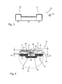
- the right seam area 21 is shown in FIG FIG. 4 shown in more detail and will be explained in more detail later representative of the two seam portions 21 and 22.
- the cushion cover center member 16 is supported by a cushioning core member 23, while the right cushion cover side member 17 is supported by a right cushion side member 24 and the left cushion cover side member 18 by a left cushion side member 25.
- the cushioning member 4 comprises a barrier layer 30 which is composed essentially of a centrally disposed barrier member 31, a right barrier layer member 32 and a left barrier layer member 33, the centrally located barrier layer member 31 attached to the cushioning core member 23, the right barrier layer member 32 to the cushioning member right upholstery side element 24 and the left barrier layer layer element 33 are correspondingly laminated to the left upholstery side element 25, specifically on a side 34 of the barrier layer layer 30 facing away from the multi-part upholstery covering device 15.
- two functional regions 40 and 41 which are spaced apart from one another by the upholstery core element 23 advantageously adjoin the seat surface 6 radially on the outside at a central mirror region 42.
- the two lateral functional areas 40 and 41 can be particularly advantageous over the right cheek cushion part 10 and the left cheek cushion pad 11 can be pulled because the pad member 4 in these two functional areas
- the upholstery side elements 17 and 18 each have a thickness 45 (numbered here only by way of example, see FIGS FIG. 4
- the upholstery reference side members 17 and 18 each have a higher elongation capacity than the upholstery reference center member 16.
- the upholstery reference center member 16 is characterized by a stretchability of 10% of its Original length, while the two upholstery reference side elements 17 and 18 each have a stretch capacity of 180% of their original length.
- the upholstery reference center element 16 and the radially laterally arranged upholstery reference side elements 17 and 18 are arranged at least partially approximately at right angles to the seat surface 6 and parallel to one another, wherein the upholstery reference element 16 and the upholstery reference side elements 17 and 18 in the respective seam regions 21 and 22, at least in this exemplary embodiment, they are sewn together by a seam 47.
- a cushioning core element abutment web 50 is provided on the cushioning core element 23 and a cushioning core element abutment web 51 is provided on the right cushioning side element 24 so that the cushion cover center element leg 48 and the upholstery side element leg 49 are in the respective Seam region 21 and 22 are advantageously held.
- the upholstery reference center element 16 is designed on the side of the barrier layer 30 in an approximately U-shaped. As a result, it forms a groove-like insertion region 52 facing the barrier layer 30, in which the cushioning core element 23 is arranged.
- the sealing strip elements 35 or 36 are in this embodiment respectively.
- Each of the sealing strip elements 35 and 36 consists of a first strip section 53, a second strip section 54 and a third strip section 55.
- the upholstery part 4 thus described so far is further backfoamed on the barrier layer layer elements 31, 32, 33 and the sealing strip elements 35 and 36 with a main cushioning element 60 (see Figures 1 and 2 ).
- the main cushion element 60 is arranged by the barrier layer 30 of the multi-part upholstery covering device 15 and the padding device 26 spatially separated on the cushion part 4.
- the upholstery reference side elements 17 and 18 can extend in the longitudinal direction of the seat part 2 or 2A and can advantageously be arranged on or above the seat surface cheek cushion parts 10 and 11 of the vehicle seat 1.
Abstract
Description
Die Erfindung betrifft einen Fahrzeugsitz mit einem Sitzteil, mit einem Rückenlehnenteil und mit einem Polsterteil zum Polstern einer Sitzfläche des Sitzteils, bei welchem das Polsterteil eine Polsterbezugeinrichtung, eine Polsterungseinrichtung, eine Sperrschichtlage sowie ein Hauptpolsterelement umfasst, und bei welchem das Hauptpolsterelement durch die Sperrschichtlage von der Polsterbezugeinrichtung und der Polsterungseinrichtung räumlich getrennt angeordnet ist.The invention relates to a vehicle seat having a seat part, with a backrest part and with a cushion part for upholstering a seat surface of the seat part, in which the cushion part comprises a cushion covering device, a cushioning device, a barrier layer layer and a main cushioning element, and wherein the main cushioning element by the barrier layer of the Polsterbezugeinrichtung and the padding device is arranged spatially separated.
Gattungsgemäße Fahrzeugsitze und diesbezügliche Fahrzeugsitzpolsterteile sind aus dem Stand der Technik vielfältig und gut bekannt. Bei diesen bekannten Fahrzeugsitzpolsterteilen sind ein Polsterbezugelement und ein Polsterelement oftmals mit einer Sperrschichtfolie kaschiert, welche an ihrer dem Polsterelement abgewandten Seite noch mit einer zusätzlichen Hauptpolsterung des Fahrzeugsitzes hinterformt ist, so dass insgesamt ein sehr kompakt bauendes Fahrzeugsitzpolsterteil zur Verfügung gestellt werden kann. Ein derartiges kompaktes Fahrzeugsitzpolsterteil ist bisher jedoch recht aufwendig herzustellen.Generic vehicle seats and related vehicle seat cushion parts are diverse and well known in the prior art. In these known vehicle seat cushion parts, a cushion cover element and a cushion element are often laminated with a barrier film, which is on its side facing away from the cushion element still behind an additional main padding of the vehicle seat, so that a total of a very compact vehicle seat cushion part can be provided. However, such a compact vehicle seat cushion part has been quite expensive to produce.
Es ist Aufgabe der vorliegenden Erfindung, gattungsgemäße Fahrzeugsitze und insbesondere gattungsgemäße Fahrzeugsitzpolsterteile derart weiterzuentwickeln, dass speziell die Herstellung von Fahrzeugsitzen insgesamt einfacher und damit auch kostengünstiger wird.It is an object of the present invention to develop generic vehicle seats and in particular generic vehicle seat cushion parts such that especially the production of vehicle seats is generally easier and thus more cost-effective.
Die Aufgabe der Erfindung wird von einem Fahrzeugsitz mit einem Sitzteil, mit einem Rückenlehnenteil und mit einem Polsterteil zum Polstern einer Sitzfläche des Sitzteils gelöst, bei welchem das Polsterteil eine Polsterbezugeinrichtung, eine Polsterungseinrichtung, eine Sperrschichtlage sowie ein Hauptpolsterelement umfasst, und bei welchem das Hauptpolsterelement durch die Sperrschichtlage von der Polsterbezugeinrichtung und der Polsterungseinrichtung räumlich getrennt angeordnet ist, wobei sich der Fahrzeugsitz dadurch auszeichnet, dass die Polsterbezugeinrichtung und die Polsterungseinrichtung in Sitzrichtung gesehen quer zur Sitzfläche und entlang der Sitzfläche derart mehrteilig ausgestaltet sind, dass das Polsterteil radial außen zwei durch einen Mittenspiegelbereich voneinander beabstandete seitliche Funktionsbereiche aufweist, wobei die seitlichen Funktionsbereiche jeweils in einem Nahtbereich an dem Mittenspiegelbereich befestigt sind.The object of the invention is achieved by a vehicle seat with a seat part, with a backrest part and with a cushion part for cushioning a seat surface of the seat part, wherein the cushioning member comprises a padding means, a cushioning means, a barrier layer and a main padding member, and wherein the main padding member is spaced apart from the padding means and the padding means by the barrier layer, the vehicle seat being characterized in that the padding means and the padding means are arranged in Seen seat direction transversely to the seat surface and along the seat surface are designed in such a multi-part, that the cushion member radially outward two spaced apart by a Mittenspiegelbereich lateral functional areas, wherein the lateral functional areas are each secured in a seam area at the central mirror area.
Durch diesen erfindungsgemäßen Aufbau, insbesondere des Polsterteils des Fahrzeugsitzes, gelingt es konstruktiv einfach, unterschiedliche Funktionsbereiche an dem Polsterteil des Fahrzeugsitzes auszugestalten, mittels welchen es möglich ist, den Fahrzeugsitz innovativ und sehr kostengünstig zu polstern.By means of this construction according to the invention, in particular of the upholstery part of the vehicle seat, it is structurally simple to design different functional areas on the upholstered part of the vehicle seat by means of which it is possible to cushion the vehicle seat in an innovative and very cost-effective manner.
Der Begriff "Polsterteil" beschreibt im Sinne der Erfindung eine Einrichtung, mittels welcher der Fahrzeugsitz gepolstert werden kann. Insofern kann das Polsterteil an dem Sitzteil und/oder an dem Rückenlehnenteil vorgesehen sein, um den Sitzkomfort für einen Benutzer des Fahrzeugsitzes komfortabler zu gestalteten. Das vorliegende Polsterteil wird vorzugsweise zumindest immer am Sitzteil vorgesehen.The term "padded part" in the context of the invention describes a device by means of which the vehicle seat can be padded. In this respect, the cushion part can be provided on the seat part and / or on the backrest part in order to make the sitting comfort more comfortable for a user of the vehicle seat. The present cushion part is preferably at least always provided on the seat part.
Der Begriff "Polsterungskernelement" beschreibt vorliegend einen weiteren Funktionsbereich bzw. eine weitere Komponente des Polsterteils, durch welchen bzw. durch welche eine besonders gute Härteabstimmung am Polsterteil, und zwar sowohl an dem Sitzteil als auch an dem Rückenlehnenteil des Fahrzeugsitzes, erzielt werden kann.The term "padding core element" herein describes a further functional area or a further component of the upholstery part, by which or by which a particularly good Tärteabstimmung on upholstery, both on the seat part and on the backrest portion of the vehicle seat, can be achieved.
Eine vorteilhafte Weiterbildung der Erfindung sieht vor, dass es vorteilhaft ist, wenn die mehrteilige Polsterbezugeinrichtung ein Polsterbezugmittenelement und in Sitzrichtung gesehen radial außen hierzu zwei seitlich angeordnete Polsterbezugseitenelemente umfasst, welche mit dem Polsterbezugmittenelement jeweils an den Nahtbereichen fest verbunden sind, wobei das Polsterbezugmittenelement von einem Polsterungskernelement der Polsterungseinrichtung und die Polsterbezugseitenelemente jeweils von einem Polsterungsseitenelement der Polsterungseinrichtung unterbaut sind. Hierdurch kann der konstruktive Aufbau des Polsterteils weiter erheblich vereinfacht werden.An advantageous development of the invention provides that it is advantageous if the multi-part upholstery covering a cushion cover center element and seen in the seating direction radially outside this two laterally arranged upholstery cover side elements which are firmly connected to the upholstery reference center element respectively at the seam areas, wherein the upholstery reference center element of a padding core element the cushioning device and the upholstery reference side elements each of a padding side element the padding device are supported. As a result, the construction of the cushion part can be further simplified considerably.
Darüber hinaus ist es vorteilhaft, wenn das Polsterungskernelement und die Polsterungsseitenelemente an ihrer der mehrteiligen Polsterbezugeinrichtung abgewandten Seite jeweils ein Sperrschichtlagenelement aufweisen, wobei die Sperrschichtlagenelemente an den Nahtbereichen jeweils mit entlang den Nahtbereichen verlaufenden Abdichtungsstreifenelementen miteinander verbunden sind. Mittels der Abdichtungsstreifenelemente kann betriebssicher eine dauerhafte Verbindung zwischen den einzelnen Sperrschichtlagenelementen erzielt werden.Moreover, it is advantageous if the cushioning core element and the cushioning side elements each have a barrier layer element on their side facing away from the multi-part cushion covering device, wherein the barrier layer layer elements are connected to each other at the seam regions with sealing strip elements running along the seam regions. By means of the sealing strip elements can be reliably achieved a permanent connection between the individual barrier layer elements elements.
Vorteilhafter Weise ist das Polsterungskernelement aus einem relativ offenporigen und damit auch sehr gut luftdurchlässigen Material realisiert, wodurch insbesondere im Bereich der direkten Sitzfläche, also dem Mittenspiegelbereich des Sitzteils und/oder des Rückenlehnenteils, eine besonders gute Atmungsaktivität am Fahrzeugsitz erzielt werden kann.Advantageously, the upholstery core element is made of a relatively open-pored and thus also very good air-permeable material, whereby a particularly good breathability can be achieved at the vehicle seat, in particular in the region of the direct seat surface, ie the center mirror region of the seat part and / or the backrest part.
Vorzugsweise umfasst das Polsterungskernelement einen Schnittschaum, einen retikulierten Schaum oder ein Abstandsgewirke, sodass es konstruktiv einfach mit guten Luftdurchlässigkeitseigenschaften realisiert werden kann.Preferably, the cushioning core element comprises a cut foam, a reticulated foam or a spacer knit, so that it can be structurally easily realized with good air permeability properties.
Insofern handelt es sich bei dem vorliegenden Polsterungskernelement vorzugsweise um ein im Wesentlichen gut luftdurchlässiges Polsterungskernelement.In this respect, the present cushioning core element is preferably a substantially air-permeable cushioning core element.
Vorteilhaft ist es, wenn das insbesondere luftdurchlässige Polsterungskernelement einstückig und nur partiell in dem Polsterteil integriert ist, sodass nicht zwingend die gesamte Sitzfläche des Fahrzeugsitzes mit dem Polsterungskernelement unterlegt ist. Vorzugsweise erstreckt sich das vorliegende Polsterungskernelement in Längserstreckung des Sitzteils und/oder des Rückenlehnenteils in etwa mittig der Sitzfläche des Sitzteils und/oder des Rückenlehnenteils. Hierdurch können die Herstellungskosten weiter reduziert werden.It is advantageous if the particular air-permeable padding core element is integrated in one piece and only partially in the padded part, so that the entire seat surface of the vehicle seat is not necessarily underlaid with the padding core element. Preferably, the present cushioning core element extends in the longitudinal extent of the seat part and / or the backrest part approximately in the middle of the seat surface of the seat part and / or the backrest part. As a result, the production costs can be further reduced.
Der Sitzkomfort kann hierbei zusätzlich je nach Einsatzzweck und Beanspruch des Fahrzeugsitzes vorteilhaft eingestellt werden, wenn das Polsterungskernelement zudem eine Dicke zwischen einschließlich 3 mm und einschließlich 50 mm, vorzugsweise eine Dicke zwischen einschließlich 15 mm und einschließlich 25 mm, und idealerweise eine Dicke zwischen einschließlich 20 mm und einschließlich 25 mm aufweist.The seat comfort here can be adjusted in addition depending on the purpose and claim of the vehicle seat advantageous if the padding core element also has a thickness of between 3 mm and 50 mm inclusive, preferably a thickness between and including 15mm and 25mm inclusive, and ideally between 20mm and 25mm inclusive.
Es hat sich herausgestellt, dass es zudem vorteilhaft ist, wenn das Polsterungskernelement eine Dicke aufweist, welche mehr als das Doppelte, vorzugsweise mehr als das Dreifache, der Dicke des verwendeten Polsterungsseitenelemente beträgt, da hierdurch eine besonders vielfältige Härteabstimmung im Bereich des Polsterungskernelements erzielt werden kann.It has been found that it is also advantageous if the cushioning core element has a thickness which is more than twice, preferably more than three times, the thickness of the cushioning side elements used, since a particularly wide range of hardness harmonization in the area of the cushioning core element can be achieved ,
Darüber hinaus ist es vorteilhaft, wenn die Dicke des Polsterungskernelements weniger als dreiviertel, vorzugsweise die Hälfte oder weniger, der Dicke des Hauptpolsterelements beträgt. Hierdurch kann sichergestellt werden, dass dem Polsterteil durch ein ausreichend hohes bzw. dickes Hauptpolsterelement insgesamt noch eine gute Festigkeit und damit eine genügend große Widerstandsfähigkeit und Formstabilität selbst bei hoher Belastung innewohnt, da das Polsterungskernelement aufgrund seiner größeren Offenporigkeit weicher ausgelegt ist als das Material des Hauptpolsterelements.Moreover, it is advantageous if the thickness of the cushioning core element is less than three quarters, preferably half or less, of the thickness of the main cushioning element. In this way it can be ensured that the upholstery element still has a good strength and thus a sufficiently high resistance and dimensional stability even at high load due to a sufficiently high or thick main upholstery element, since the upholstery core element is made softer due to its greater open porosity than the material of the main upholstery element ,
Die Dicken des Polsterungskernelements, der Polsterungsseitenelemente und des Hauptpolsterelements werden im Wesentlichen senkrecht zur Polsterbezugeinrichtung bzw. im Wesentlichen senkrecht zur planen Sitzfläche im Mittenspiegelbereich gemessen.The thicknesses of the cushioning core element, the cushioning side elements and the main cushioning element are measured essentially perpendicular to the upholstery covering device or substantially perpendicular to the plane seating surface in the middle mirror region.
Insofern sieht eine bevorzugte Ausführungsvariante vor, dass das luftdurchlässige Polsterungskernelement einen offenporigeren Materialkörper als das Hauptpolsterelement umfasst.In this respect, a preferred embodiment provides that the air-permeable padding core element comprises a porous material body as the main padding element.
Mit dem Begriff "Hauptpolsterelement" wird vorliegend jegliche Einrichtung erfasst, mittels welcher das Sitzteil bzw. das Rückenlehnenteil mit einer Grundpolsterung großflächig bedeckt und gepolstert werden kann. In der Regel wird das Hauptpolsterelement aus einem Reaktionsgemisch, etwa als Kaltschaumbauteil, erzeugt. Es kann jedoch auch aus anderen Materialien hergestellt sein, die sich gut an die Sperrschichtlage anbringen lassen. Insbesondere kann das Hauptpolsterelement auch sehr gut als Heißschaumpolster oder als Vakuumhinterschäumung realisiert sein.In the present case, the term "main cushion element" covers any device by means of which the seat part or the backrest part can be covered and padded over a large area with a basic upholstery. As a rule, the main cushion element is produced from a reaction mixture, for example as a cold foam component. However, it can also be made of other materials that can be attached well to the barrier layer. In particular, the main cushion element can also be implemented very well as a hot foam cushion or as a vacuum rear foam.
Um bei einem Hinterschäumen insbesondere des luftdurchlässigen Polsterungskernelements verhindern zu können, dass ein hierbei eingesetztes Reaktionsgemisch unbeabsichtigt in Poren des luftdurchlässigen Polsterungskernelements oder der Polsterungsseitenelemente gelangen kann, ist es vorteilhaft, wenn das Polsterungskernelement von dem Hauptpolsterelement durch die Sperrschichtlage räumlich getrennt ist.In order to be able to prevent a back-foaming, in particular of the air-permeable padding core element, that a reaction mixture used in this case unintentionally in pores of the air-permeable cushioning core element or the cushioning side elements, it is advantageous if the cushioning core element is spatially separated from the main cushioning element by the barrier layer layer.
Eine besonders vorteilhafte Ausführungsvariante sieht einen weiter strukturierten Aufbau des Polsterteils vor, bei welchem ein Polsterbezugmittenelement der mehrteiligen Polsterbezugeinrichtung und radial außen hierzu seitlich angeordneten Polsterbezugseitenelemente der mehrteiligen Polsterbezugeinrichtung an den jeweiligen Nahtbereichen zumindest teilweise in etwa rechtwinkelige zu der Sitzfläche und parallel zueinander verlaufend einander anliegend angeordnet sind, wobei das Polsterbezugmittenelement und die Polsterbezugseitenelemente in den jeweiligen Nahtbereichen miteinander vernäht oder miteinander thermisch verschweißt sind.A particularly advantageous embodiment variant provides a further structured construction of the upholstery part, in which a upholstery reference center element of the multipart upholstery covering device and laterally arranged cushion side elements of the multi-part upholstery covering device are arranged at the respective seam areas at least partially approximately perpendicular to the seat surface and parallel to each other extending adjacent to each other wherein the upholstery reference center element and the upholstery reference side elements in the respective seam regions are sewn together or thermally welded together.
Durch diesen strukturierten Aufbau können die einzelnen Polsterungselemente der Polsterungseinrichtung bereits schon während der Herstellung des Polsterteils besser gegenüber der mehrteiligen Polsterbezugeinrichtung vorpositioniert werden, so dass sich der Herstellungsprozess insgesamt noch betriebssicherer durchführen lässt.As a result of this structured construction, the individual upholstery elements of the upholstering device can already be pre-positioned better during the production of the upholstery part in relation to the multipart upholstery covering device, so that the manufacturing process as a whole can be carried out even more reliably.
Speziell für das thermische Verschweißen des Polsterbezugmittenelementes mit den Polsterbezugseitenelementen eignet sich eine Ultraschallverschweißung sehr gut. Es versteht sich, dass jedoch auch andere Füge- bzw. Verbindungstechniken zum Einsatz kommen können, um die einzelnen Elemente der mehrteiligen Polsterbezugeinrichtung dauerhaft und langlebig miteinander verbinden zu können.Especially for the thermal welding of the upholstery reference center element with the upholstery reference side elements, ultrasonic welding is very well suited. It is understood, however, that other joining or joining techniques can be used in order to be able to connect the individual elements of the multi-part upholstery covering device permanently and durably together.
Darüber hinaus ist es vorteilhaft, wenn ein Polsterbezugmittenelement der mehrteiligen Polsterbezugeinrichtung auf Seiten der Sperrschichtlage in etwa u-förmig ausgestaltet ist und einen der Sperrschichtlage zugewandten rinnenartigen Einlegebereich ausgestaltet, in welchem ein Polsterungskernelement der mehrteiligen Polsterungseinrichtung angeordnet ist. Durch diesen rinnenartig ausgestalteten Einlegebereich können die Polsterungselemente der Polsterungseinrichtung noch definierter gegenüber der mehrteiligen Polsterbezugeinrichtung platziert werden.Moreover, it is advantageous if a upholstery reference center element of the multi-part upholstery covering device is configured approximately U-shaped on the side of the barrier layer layer and forms a groove-like insertion region facing the barrier layer layer, in which a cushioning core element of the multipart cushioning device is arranged. By means of this groove-like designed insertion region, the padding elements of the padding device can be placed even more defined with respect to the multi-part padding reference device.
Hierbei ist es vorteilhaft, wenn die aus dem Polsterbezugmittenelement und aus den Polsterbezugseitenelementen zusammengesetzte mehrteilige Polsterbezugeinrichtung in eine Werkzeugform derart eingelegt wird, dass anschließend das Polsterungskernelement in den rinnenartigen Einlegebereich eingelegt und auf das Polsterbezugmittenelement aufkaschiert werden kann. Entsprechend werden die Polsterungsseitenelemente seitlich an den rinnenartigen Einlegebereich angeordnet und an den jeweiligen Polsterbezugseitenelementen aufkaschiert, so dass die mehrteilige Polsterbezugeinrichtung vorteilhaft durch die Polsterungseinrichtung unterbaut ist.In this case, it is advantageous if the multi-part upholstery covering device composed of the upholstery reference center element and of the upholstery cover side elements is inserted into a tool mold in such a way that the upholstery core element can subsequently be inserted into the groove-like insertion region and laminated onto the upholstery reference center element. Accordingly, the upholstery side elements are arranged laterally on the groove-like insertion region and laminated on the respective upholstery reference side elements, so that the multi-part upholstery covering device is advantageously supported by the padding device.
Seitlich von dem Polsterungskernelement angeordnete Funktionsbereiche des Polsterteils können vorteilhaft weiterentwickelt werden, wenn die Polsterungsseitenelemente jeweils eine Dicke aufweisen, welche geringer ist als die Dicke des Polsterungskernelements.Functional areas of the cushion part arranged on the side of the cushioning core element can advantageously be further developed if the cushioning side elements each have a thickness which is smaller than the thickness of the cushioning core element.
Insbesondere hierdurch weist das Polsterteil radial außen seitlich angeordnete Funktionsbereiche auf, welche vorteilhafter Weise ein höheres Biegungsvermögen und/oder ein höheres Dehnungsvermögen aufweisen als das Polsterteil im Bereich des Polsterungskernelements.In particular, as a result of this, the padding part has radially outwardly laterally arranged functional areas, which advantageously have a higher bending capacity and / or a higher elongation capacity than the padding part in the region of the padding core element.
Ein Bewegungsvermögen der radial außen seitlich angeordneten Funktionsbereiche kann nochmals verbessert werden, wenn die Polsterbezugseitenelemente jeweils ein höheres Dehnungsvermögen aufweisen als das Polsterbezugmittenelement, wobei insbesondere die Polsterbezugseitenelemente jeweils ein Dehnungsvermögen von 40 % bis 220 %, vorzugsweise von 60 % bis 180 %, ihrer Ursprungslängen und/oder das Polsterbezugmittenelement ein Dehnungsvermögen von 1 % bis 220 %, vorzugsweise von 10 % bis 60 %, seiner Ursprungslänge aufweisen.A mobility of the radially outwardly laterally disposed functional areas can be further improved when the upholstery reference side elements each have a higher elongation than the upholstery reference center element, wherein in particular the upholstery reference side elements each have a stretchability of 40% to 220%, preferably from 60% to 180%, of their original lengths and or the upholstery reference center element have a stretch capacity of 1% to 220%, preferably 10% to 60%, of its original length.
Sind die Polsterbezugseitenelemente sich in Längsrichtung des Sitzteils erstreckend und an bzw. oberhalb Sitzflächenwangenpolsterteilen des Fahrzeugsitzes angeordnet, kann das Polsterteil insbesondere vorteilhaft über diese Sitzflächenwangenpolsterteile gezogen werden, so dass sich eine Montage des Polsterteils am Fahrzeugsitz insgesamt vereinfachen lässt.If the upholstery reference side elements extending in the longitudinal direction of the seat part and arranged on or above Sitzflächenwangenpolsterteilen the vehicle seat, the cushion part can be particularly advantageous over this Sitzflächenwangenpolsterteile be pulled, so that a total of simplify installation of the cushion part on the vehicle seat.
Darüber hinaus sieht eine weitere bevorzugte Ausführungsvariante vor, dass die Polsterbezugseitenelemente ausgehend von einer im Wesentlichen planen Sitzfläche oberseitig dieser planen Sitzfläche nach schräg oben und anschließend nach unten gebogen weiter runterwärts bis unterseitig der planen Sitzfläche verlaufend angeordnet sind. Durch eine solche Anordnung können die Polsterbezugseitenelemente besonders vorteilhaft an einer Sitzteilkontur angepasst werden.In addition, a further preferred embodiment provides that the upholstery reference side elements, starting from a substantially planar seating surface on the upper side of this planar seating surface, are arranged obliquely upwards and then bent downwards further downwards to below the planar seating surface. By such an arrangement, the upholstery reference side elements can be particularly advantageously adapted to a seat part contour.
Damit das Polsterungsbezugmittenelement und die Polsterbezugseitenelemente in den Nahbereichen zwischen dem Polsterungskernelement und den Polsterungsseitenelementen vorteilhaft angeordnet werden können, sieht eine weiterführende vorteilhafte Ausführungsvariante vor, dass sowohl das Polsterungskernelement als auch die Polsterungsseitenelemente an ihren jeweils unmittelbar gegenüberliegenden Seiten jeweils eine Anlageeinrichtung aufweisen, zwischen denen das Polsterbezugmittenelement und das jeweilige Polsterbezugseitenelement zumindest teilweise angeordnet sind, wobei die jeweilige Anlageeinrichtung durch eine Materialüberhöhung an dem Polsterungskernelement bzw. an den Polsterungsseitenelementen ausgestaltet sind.So that the upholstery reference center element and the upholstery reference side elements can advantageously be arranged in the vicinity between the upholstery core element and the upholstery side elements, a further advantageous embodiment provides that both the upholstery core element and the upholstery side elements each have an abutment device at their respectively directly opposite sides, between which the upholstery reference center element and the respective upholstery reference side element are arranged at least partially, wherein the respective abutment means are configured by an increase in material on the cushioning core element or on the upholstery side elements.
Die Herstellung des vorliegenden Fahrzeugsitzes und insbesondere dessen Polsterteil kann weiter vereinfacht werden, wenn vor dem Applizieren der Polstereinrichtung an die mehrteilige Polsterbezugeinrichtung, idealerweise sowohl die Polsterungsseitenelemente als auch das Polsterungskernelement jeweils bereits mit einem aufkaschierten Sperrschichtelement ausgerüstet sind.The manufacture of the present vehicle seat and in particular its padded part can be further simplified if, prior to the application of the padding device to the multi-part padding covering device, ideally both the padding side elements and the padding core element are each already equipped with a laminated barrier element.
Es versteht sich, dass die zum Abdichten der vorhandenen Nahtbereiche angebrachten Abdichtungsstreifenelemente in unterschiedlichster Weise auf die Sperrschichtelemente aufgebracht bzw. an diesen befestigt werden können. Verfahrenstechnisch einfach kann dies jedoch geschehen, wenn die Abdichtungsstreifenelemente mit den Sperrschichtelementen thermisch verschweißt sind. Hierbei kann auf zusätzliche Klebemittel vorteilhaft verzichtet werden.It is understood that the sealing strip elements attached for sealing the existing seam areas can be applied in a variety of ways to the barrier layer elements or fastened to them. In terms of process technology, however, this can be done simply when the sealing strip elements are thermally welded to the barrier layer elements. This can be advantageously dispensed with additional adhesive.
Vorzugsweise bestehen die Sperrschichtelemente der Sperrschichtlage jeweils aus einer PU-Folie, welche idealerweise eine Stärke von 0,25 µm bis 1,5 µm aufweisen kann. Es versteht sich, dass auch andere Folienmaterialien vorteilhaft eingesetzt werden können, sofern sie ausreichend reißfest sind.Preferably, the barrier layer elements of the barrier layer each consist of a PU film, which may ideally have a thickness of 0.25 microns to 1.5 microns. It understands itself, that other film materials can be used advantageously, provided they are sufficiently tear-resistant.
Vorteilhafter Weise kann durch die Sperrschichtlage ein Eindringen eines Reaktionsgemisches in die Poren des Polsterungskernelement und der Polsterungsseitenelemente gut verhindert werden kann.Advantageously, penetration of a reaction mixture into the pores of the cushioning core element and the cushioning side elements can be well prevented by the barrier layer layer.
Die mehrteilige Polsterbezugeinrichtung kann vorliegend bereichsweise ein für einen Fahrzeugsitz übliches Stoffmaterial, Ledermaterial oder dergleichen umfassen.In the present case, the multi-part upholstery covering device may in some areas comprise a material material, leather material or the like which is usual for a vehicle seat.
Vorzugsweise weisen die Polsterbezugseitenelemente der mehrteiligen Polsterbezugeinrichtung eine Dicke zwischen 0,5 mm bis 6 mm auf, so dass diese sowohl gut biegbar als auch gut dehnbar sind.Preferably, the upholstery reference side elements of the multi-part upholstery covering device have a thickness of between 0.5 mm to 6 mm, so that they are both easy to bend and also easy to stretch.
Das Polsterbezugmittenelement kann ein hiervon größere Dicke aufweisen und damit vorteilhafter Weise stärker ausgelegt sein, da es im Mittenspiegelbereich angeordnet ist und im Allgemeinen stärker belastet wird als die Polsterbezugseitenelemente.The upholstery reference center element may have a greater thickness and thus be designed to be more expansive, since it is arranged in the middle mirror region and is generally loaded to a greater extent than the upholstery reference side elements.
Eine weitere sehr vorteilhafte Ausführungsvariante sieht vor, dass das Polsterteil eine Belüftungseinrichtung mit wenigstens einem Belüftungsloch umfasst, welches unterhalb des luftdurchlässigen Polsterungskernelements durch das Hauptpolsterelement hindurch bis an das vorzugsweise im Wesentlichen luftdurchlässige Polsterungskernelement oder bis wenigstens an die Sperrschichtlage des Polsterteils heranreicht. Hierdurch kann konstruktiv sehr einfach eine betriebssichere Luftzuführung bezüglich des vorzugsweise luftdurchlässigen Polsterungskernelements gewährleistet werden.Another very advantageous embodiment provides that the cushion part comprises a ventilation device with at least one ventilation hole, which extends below the air-permeable padding core element through the main cushion element to the preferably substantially air-permeable pad core element or at least to the barrier layer layer of the cushion part. As a result, a reliable air supply with respect to the preferably air-permeable pad core element can be ensured structurally very simply.
Vorteilhafter Weise sind eine Vielzahl an Belüftungslöchern vorgesehen, so dass eine besonders weiträumige und damit gute Belüftung des Polsterungskernelements erreicht werden kann.Advantageously, a plurality of ventilation holes are provided, so that a particularly spacious and thus good ventilation of the cushioning core element can be achieved.
Weist die Sperrschichtlage des Polsterteils im Bereich der Belüftungseinrichtung, insbesondere im Bereich von Belüftungslöchern der Belüftungseinrichtung, Durchbrüche auf, kann die durch die Belüftungslöcher strömende Luft auch die Sperrschichtlage ohne kritischen Widerstände passieren.If the barrier layer layer of the cushion part has openings in the region of the ventilation device, in particular in the region of ventilation holes of the ventilation device, the air flowing through the ventilation holes can also pass through the barrier layer layer without critical resistances.
Insofern ist es außergewöhnlich vorteilhaft, wenn zwischen insbesondere dem Polsterungskernelement und dem Hauptpolsterelement eine bereichsweise durchlöcherte Sperrschichtlage angeordnet ist.In this respect, it is exceptionally advantageous if a partially perforated barrier layer layer is arranged between in particular the cushioning core element and the main cushion element.
Diese Durchbrüche können durch eine geeignete Werkzeugform bereits beim Schäumen eines Reaktionsgemisches für Hauptpolsterelement oder aber erst nach dem Schäumen des Hauptpolsterelements, beispielsweise durch Brennen, Stechen, Bohren oder Fräsen, erzeugt werden.These breakthroughs can be generated by a suitable mold already during foaming of a reaction mixture for main cushion element or only after the foaming of the main cushion element, for example by burning, stinging, drilling or milling.
Nach einem weiteren Aspekt der Erfindung wird deren Aufgabe auch von dem vorliegenden Verfahren zum Herstellen eines Fahrzeugsitzpolsterteils gelöst, bei welchem in das Hauptpolsterelement wenigstens ein Belüftungsloch zum Belüften des Polsterungskernelements eingebracht wird. Durch eine derartige Verfahrensweise kann das Polsterteil für den Fahrzeugsitz besonders einfach und kostengünstig verbessert und weiterentwickelt werden.According to a further aspect of the invention, the object is also achieved by the present method for producing a vehicle seat cushion part, in which at least one ventilation hole for ventilating the cushion core element is introduced into the main cushion element. By such a procedure, the cushion part for the vehicle seat can be particularly simple and inexpensive improved and further developed.
Um einen besonders guten Luftaustausch zwischen den Belüftungslöchern und dem Polsterungskernelement bzw. eine sehr gute Frischluftzufuhr zu dem Polsterungskernelement zu erzielen, kann die Sperrschichtlage an den Belüftungslöchern zusätzlich durchstoßen sein, sofern die Sperrschichtlage von Haus aus nicht ausreichend luftdurchlässig ist.In order to achieve a particularly good exchange of air between the ventilation holes and the padding core element or a very good supply of fresh air to the padding core element, the barrier layer layer can be additionally pierced at the ventilation holes, if the barrier layer is not sufficiently permeable to air from the house.
In diesem Zusammenhang wird die Aufgabe der Erfindung auch von einem gattungsgemä-βen Fahrzeugsitzpolsterteil gelöst, welches sich dadurch auszeichnet, dass das Fahrzeugsitzpolsterteil einen von einem Hauptpolsterelement verschiedenen zusätzlichen Polsterungskernelement aufweist, in dessen mittelbar angrenzenden Bereich das Hauptpolsterelement eine Belüftungseinrichtung zum Belüften des Polsterungskernelements aufweist, bei welchem idealerweise das Polsterungskernelement unmittelbar an eine Polsterbezugeinrichtung angrenzt, und das Polsterungskernelement von dem Hauptpolsterelement durch eine Sperrschichtlage räumlich getrennt ist, wobei zumindest die Sperrschichtlage an Öffnungen von Belüftungslöchern der Belüftungseinrichtung gegebenenfalls noch durchbrochen ist. Durch einen derartigen vorteilhaften Aufbau kann insbesondere das Fahrzeugsitzpolsterteil baulich und herstellungstechnisch besonders einfach bereitgestellt werden.In this connection, the object of the invention is also achieved by a generic vehicle seat cushion part which is characterized in that the vehicle seat cushion part has an additional cushioning core element different from a main cushion element, in whose indirectly adjacent area the main cushion element has a ventilation device for aerating the cushioning core element which, ideally, the cushioning core element is immediately adjacent a pad cover, and the pad core element is spatially separated from the main pad element by a barrier layer, wherein at least the barrier layer is at openings of ventilation holes of the ventilation device is optionally still broken. By such an advantageous construction, in particular the vehicle seat upholstery part can be provided in a structurally and production-technically particularly simple manner.
Nach einem weiteren Aspekt der Erfindung wird deren Aufgabe auch von einer Verwendung eines Hauptpolsterelements eines Fahrzeugsitzpolsterteils als Belüftungseinrichtung eines in der Nähe des Hauptpolsterelements angeordneten Polsterungskernelements gelöst, da zum Realisieren einer derartigen Belüftungseinrichtung, mittels welcher insbesondere dem Polsterungskernelement vorteilhaft Frischluft zugeführt wird, im Wesentlichen nur das Hauptpolsterelement erforderlich ist, wodurch vorteilhafter Weise auf zusätzliche Belüftungseinrichtungsbauteile an oder in dem Hauptpolsterelement verzichtet werden kann.According to a further aspect of the invention, the object is also achieved by using a main cushion element of a vehicle seat cushion part as ventilation device of a arranged in the vicinity of the main cushion padding core element, as to realize such a ventilation device by means of which in particular the cushioning core element advantageously fresh air is supplied, essentially only the Main cushion element is required, which advantageously can be dispensed with additional ventilation device components on or in the main cushion element.
Es ist hier ausdrücklich darauf hingewiesen, dass die Merkmale der vorstehend beschriebenen Lösungen auch kombiniert werden können, um die hierzu genannten Vorteile und/oder weitere Vorteile entsprechend kumuliert umsetzen zu können.It is expressly pointed out here that the features of the solutions described above can also be combined in order to be able to implement the advantages and / or further advantages cited in this regard in a cumulative manner.
Weitere Vorteile, Eigenschaften der vorliegenden Erfindung werden anhand anliegender Zeichnung und nachfolgender Beschreibung erläutert, in welchen beispielhaft ein Fahrzeugsitz mit einem erfindungsgemäßen Polsterteil dargestellt und beschrieben ist.Further advantages, properties of the present invention will be explained with reference to the accompanying drawings and the following description, in which an example of a vehicle seat is shown and described with a cushion part according to the invention.
In der Zeichnung zeigen:
Figur 1- schematisch eine teilweise geschnittene perspektivische Teilansicht eines Fahrzeugsitzes umfassend ein Polsterteil mit einer mehrteiligen Polsterbezugeinrichtung, welches mit einer mehrteiligen Polsterungseinrichtung unterbaut ist, wobei die einzelnen Polsterungselemente der Polsterungseinrichtung mit Sperrschichtlagenelementen ausgerüstet sind, die in Nahtbereichen des Polsterteils entlang dieser Nahtbereiche mit Abdichtungsstreifenelementen miteinander verschweißt sind;
Figur 2- schematisch eine Querschnittsansicht des Polsterteils aus der
Figur 1 Figur 3- schematisch eine Ansicht einer bevorzugten Querschnittsform eines alternativen Sitzteils; und
Figur 4- schematisch eine Detailansicht eines der Nahtbereiche des Polsterteils aus
den Figur 1 .bis Figur 3
- FIG. 1
- schematically a partially sectioned partial perspective view of a vehicle seat comprising a cushion part with a multi-part upholstery covering device, which is supported with a multi-part padding device, wherein the individual padding elements of the padding device are equipped with barrier layer elements which are welded together in seam areas of the pad along these seam areas with Abdichtungsstreifenelementen;
- FIG. 2
- schematically a cross-sectional view of the cushion part of the
FIG. 1 ; - FIG. 3
- schematically a view of a preferred cross-sectional shape of an alternative seat part; and
- FIG. 4
- schematically shows a detail of one of the seam portions of the cushion part of the
FIG. 1 to FIG. 3 ,
Der in der
Das Polsterteil 4 gestaltet im Wesentlichen eine Sitzfläche 6 und das Polsterteil 5 im Wesentlichen eine Sitzfläche 7 des Rückenlehnenteils 3 aus. Hinsichtlich des Rückenlehnenteils 3 sind noch seitliche Wangenpolsterteile 8 und 9 dargestellt, welche hinsichtlich des Sitzteils 2 gemäß der Darstellung nach der
Das Polsterteil 4 umfasst im Wesentlichen eine mehrteilige Polsterbezugeinrichtung 15, welche aus einem Polsterbezugmittenelement 16, einem rechten Polsterbezugseitenelement 17 und einem linken Polsterbezugseitenelement 18 besteht (siehe insbesondere
Hierbei ist das rechte Polsterbezugseitenelement 17 in einem rechten Nahtbereich 21 mit dem Polsterbezugmittenelement 16 verbunden und das linke Polsterbezugsseitenelement 18 ist in einem linken Nahtbereich 22 mit dem Polsterbezugmittenelement 16 fest verbunden (siehe
Das Polsterbezugmittenelement 16 ist von einem Polsterungskernelement 23 unterbaut, während das rechte Polsterbezugseitenelement 17 von einem rechten Polsterungsseitenelement 24 und das linke Polsterbezugseitenelement 18 von einem linken Polsterungsseitenelement 25 unterbaut sind.The cushion
Das mittig angeordnete Polsterungskernelement 23 und die beiden seitlich hierzu angeordneten Polsterungsseitenelemente 24 und 25 bilden zusammen eine Polsterungseinrichtung 26 des Polsterteils 4.The centrally arranged
Des Weiteren weist das Polsterteil 4 eine Sperrschichtlage 30 auf, die sich im Wesentlichen durch ein mittig angeordnetes Sperrschichtelement 31, ein rechtes Sperrschichtlagenelement 32 und ein linkes Sperrschichtlagenelement 33 zusammensetzt, wobei das mittig angeordnete Sperrschichtlagenelement 31 an dem Polsterungskernelement 23, das rechte Sperrschichtlagenelement 32 an dem rechten Polsterungsseitenelement 24 und das linke Sperrschichtlagenelement 33 dementsprechend an das linke Polsterungsseitenelement 25 ankaschiert sind, und zwar an einer der mehrteiligen Polsterbezugeinrichtung 15 abgewandten Seite 34 der Sperrschichtlage 30.Further, the cushioning
An den Nahtbereichen 21 bzw. 22 ist das jeweilige rechte bzw. linke Sperrschichtlagenelement 32 bzw. 33 mit dem mittigen Sperrschichtlagenelement 31 durch Abdichtungsstreifenelemente 35 bzw. 36 miteinander verbunden, wobei der Aufbau dieser rechten und linken Abdichtungsstreifenelemente 35 bzw. 36 stellvertretend im Zusammenhang mit dem rechten Nahtbereich 21 (siehe
In vorteilhafter Weise ergeben sich durch diesen Aufbau des Polsterteils 4 an dem Polsterteil 4 zwei voneinander durch das Polsterungskernelement 23 beabstandete Funktionsbereiche 40 bzw. 41, die radial 20 außen an einem Mittenspiegelbereich 42 der Sitzfläche 6 anschließen.By virtue of this structure of the
Bezugnehmend auf das in der
In dem jeweiligen Nahtbereich 21 bzw. 22 sind das Polsterbezugmittenelement 16 und die radial 20 seitlich angeordneten Polsterbezugseitenelemente 17 bzw. 18 zumindest teilweise in etwa rechtwinkelig zu der Sitzfläche 6 und parallel zueinander verlaufend aneinander anliegend angeordnet, wobei das Polsterbezugmittenelement 16 und die Polsterbezugseitenelemente 17 und 18 in den jeweiligen Nahtbereichen 21 bzw. 22 zumindest in diesem Ausführungsbeispiel durch eine Naht 47 miteinander vernäht sind.In the
Dadurch, dass das Polsterbezugmittelelement 16 bzw. die Polsterbezugseitenelemente 17 und 18 in etwa rechtwinkelig zu der Sitzfläche 6 verlaufend angeordnet sind, liegen einerseits ein Polsterbezugmittenelementschenkel 48 und andererseits ein Polsterbezugseitenelementschenkel 49 direkt aneinander.Due to the fact that the
Damit diese Schenkel 48 und 49 in dem jeweiligen Nahtbereich 21 bzw. 22 zusätzlich stabilisiert werden können, ist an dem Polsterungskernelement 23 ein Polsterungskernelementanlagesteg 50 und an dem rechten Polsterungsseitenelement 24 ein Polsterungskernelementanlagesteg 51 vorgesehen, so dass der Polsterbezugmittenelementschenkel 48 und der Polsterbezugseitenelementschenkel 49 in dem jeweiligen Nahtbereich 21 bzw. 22 vorteilhaft gehalten sind.To additionally stabilize these
Das Polsterbezugmittenelement 16 ist auf Seiten der Sperrschichtlage 30 in etwa u-förmig ausgestaltet. Dadurch gestaltet es einen der Sperrschichtlage 30 zugewandten rinnenartigen Einlegebereich 52 aus, in welchem das Polsterungskernelement 23 angeordnet ist.The upholstery
Um an den Nahtbereichen 21 bzw. 22 die Abdichtungsstreifenelemente 35 bzw. 36 insbesondere an dem Polsterungskernelementanlagesteg 50 und an den Polsterungsseitenelementanlagestege 51 vorteilhaft auf die jeweiligen Sperrsichtlagenelemente 31, 32, bzw. 33 anbringen zu können, sind die Abdichtungsstreifenelemente 35 und 36 in diesem Ausführungsbeispiel jeweils mehrteilig ausgestaltet, wobei jedes der Abdichtungsstreifenelemente 35 und 36 aus einem ersten Streifenabschnitt 53, einem zweiten Streifenabschnitt 54 und einem dritten Streifenabschnitt 55 bestehen. Hierdurch können vorteilhafter Weise eventuell vorhandene Höhendifferenzen an den Anlagestegen 50 und 51 (siehe insbesondere
Das derart bisher beschriebene Polsterteil 4 wird darüber hinaus an den Sperrschichtlagenelementen 31, 32, 33 und den Abdichtungsstreifenelementen 35 und 36 mit einem Hauptpolsterelement 60 hinterschäumt (siehe
Wie im Wesentlichen ebenfalls aus der
Insofern sind hierbei die Polsterbezugseitenelemente 17 bzw. 18 ausgehend von einer im Wesentlichen planen Sitzfläche 6 oberseitig in dieser planen Sitzfläche 6 nach schräg oben und anschließend nach unten gebogen weiter runterwärts bis unterseitig der planen Sitzfläche 6 verlaufend angeordnet.In this respect, in this case, the upholstery
Es versteht sich, dass es sich bei den erläuterten Ausführungsbeispielen lediglich um eine erste Ausgestaltung des erfindungsgemäßen Fahrzeugsitzes handelt. Insofern beschränkt sich die Ausgestaltung der Erfindung nicht allein auf dieses Ausführungsbeispiel.It is understood that the illustrated exemplary embodiments are only a first embodiment of the vehicle seat according to the invention. In this respect, the embodiment of the invention is not limited to this embodiment alone.
Sämtliche in den Anmeldungsunterlagen offenbarten Merkmale werden als erfindungswesentlich beansprucht, sofern sie einzeln oder in Kombination gegenüber dem Stand der Technik neu sind.All disclosed in the application documents features are claimed as essential to the invention, provided they are new individually or in combination over the prior art.
- 11
- Fahrzeugsitzvehicle seat
- 22
- Sitzteilseat part
- 2A2A
- alternatives Sitzteilalternative seat part
- 33
- RückenlehnenteilBackrest part
- 44
- Polsterteil des SitzteilsUpholstered part of the seat part
- 55
- Polsterteil des RückenlehnenteilsUpholstered part of the backrest part
- 66
- Sitzfläche des SitzteilsSeat of the seat part
- 77
- Sitzfläche des RückenlehnenteilsSeat of the backrest part
- 88th
- rechtes Rückenlehnenwangenpolsterteilright backrest cheek cushion part
- 99
- linkes Rückenlehnenwangenpolsterteilleft backrest cheek cushion part
- 1010
- rechtes Sitzwangenpolsterteilright seat cheek cushion part
- 1111
- linkes Sitzwangenpolsterteilleft seat cheek cushion part
- 1515
- PolsterbezugeinrichtungUpholstery facility
- 1616
- PolsterbezugmittenelementUpholstery middle element
- 1717
- rechtes Polsterbezugseitenelementright upholstery reference side element
- 1818
- linkes Polsterbezugseitenelementleft upholstery cover side element
- 1919
- Sitzrichtungseat direction
- 2020
- radialradial
- 2121
- rechter Nahtbereichright seam area
- 2222
- linker Nahtbereichleft seam area
- 2323
- PolsterungskernelementUpholstery core element
- 2424
- rechtes Polsterungsseitenelementright upholstery side element
- 2525
- linkes Polsterungsseitenelementleft upholstery side element
- 2626
- Polsterungseinrichtungpadding device
- 3030
- SperrschichtlageBarrier layer
- 3131
- mittiges Sperrschichtlagenelementcentral barrier layer element
- 3232
- rechtes Sperrschichtlagenelementright barrier layer element
- 3333
- linkes Sperrschichtlagenelementleft barrier layer element
- 3434
- abgewandte Seiteopposite side
- 3535
- rechtes Abdichtungsstreifenelementright sealing strip element
- 3636
- linkes Abdichtungsstreifenelementleft sealing strip element
- 4040
- rechter Funktionsbereichright functional area
- 4141
- linker Funktionsbereichleft functional area
- 4242
- MittenspiegelbereichMid-level range
- 4545
- PolsterungsseitenelementdickeUpholstery side element thickness
- 4646
- PolsterungskernelementdickeUpholstery core element thickness
- 4747
- Nahtseam
- 4848
- PolsterbezugmittenelementschenkelUpholstery middle element leg
- 4949
- PolsterbezugseitenelementschenkelUpholstery side element leg
- 5050
- PolsterungskernelementanlagestegUpholstery core element bearing web
- 5151
- PolsterungsseitenelementanlagestegUpholstery element bearing web page
- 5252
- Einlegebereichloading area
- 5353
- erster Streifenabschnittfirst strip section
- 5454
- zweiter Streifenabschnittsecond strip section
- 5555
- dritter Streifenabschnittthird strip section
- 6060
- HauptpolsterelementMain upholstery element
- 6161
- Längsrichtunglongitudinal direction
Claims (10)
dadurch gekennzeichnet, dass
die Polsterbezugeinrichtung (15) und die Polsterungseinrichtung (26) in Sitzrichtung (19) gesehen quer zur Sitzfläche (6, 7) und entlang der Sitzfläche (6, 7) derart mehrteilig ausgestaltet sind, dass das Polsterteil (4, 5) radial (20) außen zwei durch einen Mittenspiegelbereich (42) voneinander beabstandete seitliche Funktionsbereiche (40, 41) aufweist, wobei die seitlichen Funktionsbereiche (40, 41) jeweils in einem Nahtbereich (21, 22) an dem Mittenspiegelbereich (42) befestigt sind.Vehicle seat (1) with a seat part (2), with a backrest part (3) and with a cushion part (4, 5) for upholstering a seat surface (6, 7) of the seat part (2, 2A), in which the cushion part (4, 5) comprises a padding device (15), a padding device (26), a barrier layer (30) and a main padding element, and in which the main padding element (60) passes through the barrier layer (30) of the padding device (15) and the padding device (26). is arranged spatially separated,
characterized in that
the upholstery covering device (15) and the upholstering device (26) in the seat direction (19) are configured so as to be multi-part transverse to the seat surface (6, 7) and along the seat surface (6, 7) such that the cushion part (4, 5) extends radially (20 ) on the outside two by a central mirror region (42) spaced-apart lateral functional areas (40, 41), wherein the lateral functional areas (40, 41) in each case in a seam region (21, 22) on the central mirror region (42) are attached.
dadurch gekennzeichnet, dass
die mehrteilige Polsterbezugeinrichtung (15) ein Polsterbezugmittenelement (16) und in Sitzrichtung (19) gesehen radial (20) außen hierzu zwei seitlich angeordnete Polsterbezugseitenelemente (17, 16) umfasst, welche mit dem Polsterbezugmittenelement (16) jeweils an den Nahtbereichen (21, 22) fest verbunden sind, wobei das Polsterbezugmittenelement (16) von einem Polsterungskernelement (23) der Polsterungseinrichtung (26) und die Polsterbezugseitenelemente (17, 16) jeweils von einem Polsterungsseitenelement (24, 25) der Polsterungseinrichtung (26) unterbaut sind.Vehicle seat (1) according to claim 1,
characterized in that
the multi-part upholstery covering device (15) comprises a upholstery reference center element (16) and radially (20) seen laterally in the seat direction (19), comprising two laterally arranged upholstery reference side elements (17, 16) which are connected to the upholstery reference center element (16) at the seam regions (21, 22 ), wherein the cushion cover center element (16) is supported by a cushioning core element (23) of the cushioning device (26) and the cushion cover side elements (17, 16) are each supported by a cushioning side element (24, 25) of the cushioning device (26).
dadurch gekennzeichnet, dass
das Polsterungskernelement (23) und die Polsterungsseitenelemente (24, 25) an ihrer der mehrteiligen Polsterbezugeinrichtung (15) abgewandten Seite (34) jeweils ein Sperrschichtlagenelement (31, 32, 33) aufweisen, wobei die Sperrschichtlagenelemente (31, 32, 33) an den Nahtbereichen (21, 22) jeweils mit entlang den Nahtbereichen (21, 22) verlaufenden Abdichtungsstreifenelementen (35, 36) miteinander verbunden sind.Vehicle seat (1) according to claim 2,
characterized in that
the upholstery core element (23) and the upholstery side elements (24, 25) each have a barrier layer layer element (31, 32, 33) on their side (34) facing away from the multipart cushion cover device (15), wherein the barrier layer layer elements (31, 32, 33) contact the Seam regions (21, 22) each with along the seam regions (21, 22) extending sealing strip elements (35, 36) are interconnected.
dadurch gekennzeichnet, dass
ein Polsterbezugmittenelement (16) der mehrteiligen Polsterbezugeinrichtung (15) und radial (20) hierzu seitlich angeordneten Polsterbezugseitenelemente (17, 18) der mehrteiligen Polsterbezugeinrichtung (15) an den jeweiligen Nahtbereichen (21, 22) zumindest teilweise in etwa rechtwinkelig zu der Sitzfläche (6, 7) und parallel zueinander verlaufend aneinander anliegend angeordnet sind, wobei das Polsterbezugmittenelement (16) und die Polsterbezugseitenelemente (17, 18) in den jeweiligen Nahtbereichen (21, 22) miteinander vernäht oder miteinander thermisch verschweißt sind.Vehicle seat (1) according to one of claims 1 to 3,
characterized in that
an upholstery reference center element (16) of the multi-part upholstery covering device (15) and radially (20) laterally arranged upholstery reference side elements (17, 18) of the multi-part upholstery covering device (15) at the respective seam regions (21, 22) at least partially approximately at right angles to the seat surface (6 7, 7) and the upholstery reference side elements (17, 18) in the respective seam regions (21, 22) are sewn together or thermally welded together.
dadurch gekennzeichnet, dass
ein Polsterbezugmittenelement (16) der mehrteiligen Polsterbezugeinrichtung (15) auf Seiten der Sperrschichtlage (30) in etwa u-förmig ausgestaltet ist und dadurch einen der Sperrschichtlage (30) zugewandten rinnenartigen Einlegebereich (52) ausgestaltet, in welchem ein Polsterungskernelement (23) der mehrteiligen Polsterungseinrichtung (26) angeordnet ist.Vehicle seat (1) according to one of claims 1 to 4,
characterized in that
an upholstery reference center element (16) of the multipart upholstery covering device (15) is configured approximately U-shaped on the side of the barrier layer layer (30) and thereby forms a groove-like insertion region (52) facing the barrier layer layer (30), in which a cushioning core element (23) of the multipart Padding device (26) is arranged.
dadurch gekennzeichnet, dass
Polsterungsseitenelemente (24, 25) der mehrteiligen Polsterungseinrichtung (26) jeweils eine Dicke (45) aufweisen, welche geringer ist als eine Dicke (46) eines Polsterungskernelementes (23) der mehrteiligen Polsterungseinrichtung (26), wodurch das Polsterteil (4, 5) radial (20) außen seitlich angeordnete Funktionsbereiche (40, 41) aufweist, welche ein höheres Biegungsvermögen und/oder ein höheres Dehnungsvermögen aufweisen als das Polsterteil (4, 5) im Bereich des Polsterungskernelement (23).Vehicle seat (1) according to one of claims 1 to 5,
characterized in that
Padding side elements (24, 25) of the multi-part padding device (26) each have a thickness (45) which is smaller than a thickness (46) of a padding core element (23) of the multi-part padding device (26), whereby the padding part (4, 5) radially (20) on the outside laterally arranged functional areas (40, 41), which has a higher bending capacity and / or a higher Have expansibility than the cushion part (4, 5) in the region of the padding core element (23).
dadurch gekennzeichnet, dass
Polsterbezugseitenelemente (17, 18) der mehrteiligen Polsterbezugeinrichtung (15) jeweils ein höheres Dehnungsvermögen aufweisen als ein Polsterbezugmittenelement (16) der mehrteiligen Polsterbezugeinrichtung (15), wobei insbesondere die Polsterbezugseitenelemente (17, 18) jeweils ein Dehnungsvermögen von 40% bis 220%, vorzugsweise von 60% bis 180%, ihrer Ursprungslängen und/oder das Polsterbezugmittenelement (16) ein Dehnungsvermögen von 1% bis 220%, vorzugsweise von 10% bis 60%, seiner Ursprungslänge aufweisen.Vehicle seat (1) according to one of claims 1 to 6,
characterized in that
Upholstery reference side elements (17, 18) of the multi-part upholstery covering device (15) each have a higher elongation than a upholstery reference center element (16) of the multi-part upholstery covering device (15), wherein in particular the upholstery reference side elements (17, 18) each have a stretching capacity of 40% to 220%, preferably from 60% to 180%, of their original lengths and / or the upholstery reference center element (16), have an elongation capacity of 1% to 220%, preferably of 10% to 60%, of their original length.
dadurch gekennzeichnet, dass
Polsterbezugseitenelemente (17, 18) der mehrteiligen Polsterbezugeinrichtung (15) sich in Längsrichtung (61) des Sitzteils (2, 2A) erstreckend und an bzw. oberhalb Sitzflächenwangenpolsterteilen (10, 11) des Fahrzeugsitzes (1) angeordnet sind.Vehicle seat (1) according to one of claims 1 to 7,
characterized in that
Upholstery reference side elements (17, 18) of the multi-part upholstery covering device (15) extending in the longitudinal direction (61) of the seat part (2, 2A) and on or above Sitzflächenwangenpolsterteilen (10, 11) of the vehicle seat (1) are arranged.
dadurch gekennzeichnet, dass
Polsterbezugseitenelemente (17, 18) der mehrteiligen Polsterbezugeinrichtung (15) ausgehend von einer im Wesentlichen planen Sitzfläche (6, 7) oberseitig dieser planen Sitzfläche (6, 7) nach oben und anschießend nach unten gebogen weiter runterwärts bis unterseitig der planen Sitzfläche (6, 7) verlaufend angeordnet sind.Vehicle seat (1) according to one of claims 1 to 8,
characterized in that
Upholstery reference side elements (17, 18) of the multi-part upholstery covering device (15) starting from a substantially planar seat surface (6, 7) on the upper side of this planar seat surface (6, 7) bent upward and subsequently downward further downwards to below the planar seat surface (6, 7) are arranged to extend.
dadurch gekennzeichnet, dass
sowohl ein Polsterungskernelement (23) der mehrteiligen Polsterungseinrichtung (26) als auch Polsterungsseitenelemente (24, 25) der mehrteiligen Polsterungseinrichtung (26) an ihren jeweils unmittelbar gegenüberliegenden Seiten jeweils eine Anlageeinrichtung (50, 51) aufweisen, zwischen denen ein Polsterbezugmittenelement (16) der mehrteiligen Polsterbezugeinrichtung (15) und ein jeweiliges Polsterbezugseitenelement (17, 18) der mehrteiligen Polsterbezugeinrichtung (15) zumindest teilweise angeordnet sind, wobei insbesondere die jeweilige Anlageeinrichtung (50, 51) durch eine Materialüberhöhung an dem Polsterungskernelement (23) bzw. an den Polsterungsseitenelementen (24, 25) ausgestaltet sind.Vehicle seat (1) according to one of claims 1 to 9,
characterized in that
both a padding core element (23) of the multi-part padding device (26) and padding side elements (24, 25) of the multi-part padding device (26) each have on their respectively directly opposite sides a contact device (50, 51) between which a padding reference center element (16) of multi-part upholstery covering device (15) and a respective upholstery reference side element (17, 18) of the multi-part upholstery covering device (15) are at least partially arranged, wherein in particular the respective contact device (50, 51) are configured by an increase in material on the padding core element (23) or on the padding side elements (24, 25).
Applications Claiming Priority (1)
| Application Number | Priority Date | Filing Date | Title |
|---|---|---|---|
| DE102011122011.2A DE102011122011B4 (en) | 2011-12-22 | 2011-12-22 | Vehicle seat with upholstered part with seam area |
Publications (2)
| Publication Number | Publication Date |
|---|---|
| EP2607154A1 true EP2607154A1 (en) | 2013-06-26 |
| EP2607154B1 EP2607154B1 (en) | 2015-08-19 |
Family
ID=47500971
Family Applications (1)
| Application Number | Title | Priority Date | Filing Date |
|---|---|---|---|
| EP12197436.4A Active EP2607154B1 (en) | 2011-12-22 | 2012-12-17 | Vehicle seat with cushion with seam area |
Country Status (2)
| Country | Link |
|---|---|
| EP (1) | EP2607154B1 (en) |
| DE (1) | DE102011122011B4 (en) |
Cited By (1)
| Publication number | Priority date | Publication date | Assignee | Title |
|---|---|---|---|---|
| FR3021002A1 (en) * | 2014-05-19 | 2015-11-20 | Cera | HEADREST FOR THE SEAT OF A MOTOR VEHICLE |
Citations (6)
| Publication number | Priority date | Publication date | Assignee | Title |
|---|---|---|---|---|
| WO1995014409A1 (en) * | 1993-11-22 | 1995-06-01 | Amerigon, Inc. | Variable temperature seat |
| DE102004001912A1 (en) * | 2004-01-14 | 2005-08-11 | Faurecia Autositze Gmbh & Co. Kg | Ventilated seat for motor vehicle, has air manifold channel that is extended parallel and adjacent to ventilation section and cushion cover, and ventilation channel and manifold channel that are connected by separate air duct units |
| US20060175877A1 (en) * | 2005-02-07 | 2006-08-10 | L&P Property Management Company | Heat, cool, and ventilate system for automotive applications |
| DE202007002196U1 (en) * | 2007-02-14 | 2007-05-10 | Isringhausen Gmbh & Co. Kg | Foam padding for vehicle seating, comprises two planar foam parts from hardened polymer material, and humidity-transporting intermediate layer arranged between the two foam parts |
| DE102007055034A1 (en) * | 2007-11-15 | 2009-05-20 | Keiper Gmbh & Co. Kg | Seat e.g. driver seat, for e.g. commercial motor vehicle, has ventilation device provided with pressure/low pressure transformer, and high pressure source for generation of high pressure for pneumatic functions in vehicle |
| DE102008061594A1 (en) * | 2007-12-12 | 2009-06-18 | Lear Corp., Southfield | An attachment arrangement for attaching trim material to the padding of a ventilated seat |
Family Cites Families (3)
| Publication number | Priority date | Publication date | Assignee | Title |
|---|---|---|---|---|
| US5236243A (en) * | 1992-03-30 | 1993-08-17 | General Motors Corporation | Serge thread loop fastener for trim cover |
| FR2867116B1 (en) * | 2004-03-08 | 2006-07-07 | Cera | VENTILATED GARMENT COMPONENT FOR MOTOR VEHICLE SEAT |
| FR2897023B1 (en) * | 2006-02-06 | 2008-04-18 | Faurecia Sieges Automobile | MOTOR VEHICLE SEAT ELEMENT CUSHION AND METHOD OF MANUFACTURING SUCH CUSHION |
-
2011
- 2011-12-22 DE DE102011122011.2A patent/DE102011122011B4/en not_active Expired - Fee Related
-
2012
- 2012-12-17 EP EP12197436.4A patent/EP2607154B1/en active Active
Patent Citations (6)
| Publication number | Priority date | Publication date | Assignee | Title |
|---|---|---|---|---|
| WO1995014409A1 (en) * | 1993-11-22 | 1995-06-01 | Amerigon, Inc. | Variable temperature seat |
| DE102004001912A1 (en) * | 2004-01-14 | 2005-08-11 | Faurecia Autositze Gmbh & Co. Kg | Ventilated seat for motor vehicle, has air manifold channel that is extended parallel and adjacent to ventilation section and cushion cover, and ventilation channel and manifold channel that are connected by separate air duct units |
| US20060175877A1 (en) * | 2005-02-07 | 2006-08-10 | L&P Property Management Company | Heat, cool, and ventilate system for automotive applications |
| DE202007002196U1 (en) * | 2007-02-14 | 2007-05-10 | Isringhausen Gmbh & Co. Kg | Foam padding for vehicle seating, comprises two planar foam parts from hardened polymer material, and humidity-transporting intermediate layer arranged between the two foam parts |
| DE102007055034A1 (en) * | 2007-11-15 | 2009-05-20 | Keiper Gmbh & Co. Kg | Seat e.g. driver seat, for e.g. commercial motor vehicle, has ventilation device provided with pressure/low pressure transformer, and high pressure source for generation of high pressure for pneumatic functions in vehicle |
| DE102008061594A1 (en) * | 2007-12-12 | 2009-06-18 | Lear Corp., Southfield | An attachment arrangement for attaching trim material to the padding of a ventilated seat |
Cited By (1)
| Publication number | Priority date | Publication date | Assignee | Title |
|---|---|---|---|---|
| FR3021002A1 (en) * | 2014-05-19 | 2015-11-20 | Cera | HEADREST FOR THE SEAT OF A MOTOR VEHICLE |
Also Published As
| Publication number | Publication date |
|---|---|
| DE102011122011A1 (en) | 2013-06-27 |
| EP2607154B1 (en) | 2015-08-19 |
| DE102011122011B4 (en) | 2016-01-21 |
Similar Documents
| Publication | Publication Date | Title |
|---|---|---|
| EP2049363B1 (en) | Actively ventilated vehicle seat | |
| EP2941366B1 (en) | Foam part, in particular for a vehicle seat, and method and tool for producing a foam part | |
| EP2517928B1 (en) | Vehicle seat and method for producing a vehicle seat upholstery section | |
| EP1962644B1 (en) | Spring element unit for a padding element, especially a mattress | |
| EP3083327B1 (en) | Foam part, in particular for a vehicle seat, and vehicle seat | |
| EP2826663A1 (en) | Air conditioning unit for a vehicle seat | |
| AT509326B1 (en) | SUPPORT GROUP FOR PASSENGER SEAT AND PASSENGER SEAT | |
| DE102013213995B4 (en) | Backrest for a vehicle seat and vehicle seat | |
| DE102011121991B4 (en) | Vehicle seat and method for manufacturing a vehicle seat cushion part | |
| EP2049362B2 (en) | Air-conditioned motor vehicle seat | |
| EP2607154B1 (en) | Vehicle seat with cushion with seam area | |
| DE102010005728A1 (en) | Seat part assembly for e.g. back rest part, of surface of vehicle seat, has seat part frames and textile layers that are covered by covers, ventilators arranged at distance from textile layer and clamped on covering part | |
| DE102006001225A1 (en) | Air-conditioned upholstered part, especially for a "passive climate seat" | |
| EP2607156B1 (en) | Vehicle seat, method for producing a vehicle seat upholstery part and use of a hot press stamp | |
| DE10338525A1 (en) | Vehicle seat with ventilation layer, includes depressions formed by plastic deformation of spirally-formed underbody in which fasteners to lower layer are fitted | |
| EP2199080B1 (en) | Method for producing a planar structure, in particular an upholstery element support, such a planar structure and an upholstery element | |
| EP3782831A1 (en) | Insert for the air conditioning of a vehicle and method for manufacturing an insert for air conditioning | |
| AT503919B1 (en) | LUGGAGE FOR A SEAT | |
| DE102014006872A1 (en) | Cushion for a seat system of a vehicle, in particular a passenger car | |
| DE2450806A1 (en) | Composite sheets with foam polyurethane core between covers - and fabricated into contoured upholstery by direct cover to cover welded seams | |
| DE3641472A1 (en) | Cushion with covering for vehicle seats and process for the production thereof | |
| DE102006061004B4 (en) | Cover for a mattress |
Legal Events
| Date | Code | Title | Description |
|---|---|---|---|
| AK | Designated contracting states |
Kind code of ref document: A1 Designated state(s): AL AT BE BG CH CY CZ DE DK EE ES FI FR GB GR HR HU IE IS IT LI LT LU LV MC MK MT NL NO PL PT RO RS SE SI SK SM TR |
|
| AX | Request for extension of the european patent |
Extension state: BA ME |
|
| PUAI | Public reference made under article 153(3) epc to a published international application that has entered the european phase |
Free format text: ORIGINAL CODE: 0009012 |
|
| 17P | Request for examination filed |
Effective date: 20131031 |
|
| RBV | Designated contracting states (corrected) |
Designated state(s): AL AT BE BG CH CY CZ DE DK EE ES FI FR GB GR HR HU IE IS IT LI LT LU LV MC MK MT NL NO PL PT RO RS SE SI SK SM TR |
|
| GRAP | Despatch of communication of intention to grant a patent |
Free format text: ORIGINAL CODE: EPIDOSNIGR1 |
|
| INTG | Intention to grant announced |
Effective date: 20150601 |
|
| GRAS | Grant fee paid |
Free format text: ORIGINAL CODE: EPIDOSNIGR3 |
|
| GRAA | (expected) grant |
Free format text: ORIGINAL CODE: 0009210 |
|
| AK | Designated contracting states |
Kind code of ref document: B1 Designated state(s): AL AT BE BG CH CY CZ DE DK EE ES FI FR GB GR HR HU IE IS IT LI LT LU LV MC MK MT NL NO PL PT RO RS SE SI SK SM TR |
|
| REG | Reference to a national code |
Ref country code: GB Ref legal event code: FG4D Free format text: NOT ENGLISH |
|
| REG | Reference to a national code |
Ref country code: CH Ref legal event code: EP |
|
| REG | Reference to a national code |
Ref country code: IE Ref legal event code: FG4D Free format text: LANGUAGE OF EP DOCUMENT: GERMAN |
|
| REG | Reference to a national code |
Ref country code: AT Ref legal event code: REF Ref document number: 743550 Country of ref document: AT Kind code of ref document: T Effective date: 20150915 |
|
| REG | Reference to a national code |
Ref country code: DE Ref legal event code: R096 Ref document number: 502012004196 Country of ref document: DE |
|
| REG | Reference to a national code |
Ref country code: FR Ref legal event code: PLFP Year of fee payment: 4 |
|
| REG | Reference to a national code |
Ref country code: LT Ref legal event code: MG4D |
|
| REG | Reference to a national code |
Ref country code: NL Ref legal event code: MP Effective date: 20150819 |
|
| PG25 | Lapsed in a contracting state [announced via postgrant information from national office to epo] |
Ref country code: NO Free format text: LAPSE BECAUSE OF FAILURE TO SUBMIT A TRANSLATION OF THE DESCRIPTION OR TO PAY THE FEE WITHIN THE PRESCRIBED TIME-LIMIT Effective date: 20151119 Ref country code: GR Free format text: LAPSE BECAUSE OF FAILURE TO SUBMIT A TRANSLATION OF THE DESCRIPTION OR TO PAY THE FEE WITHIN THE PRESCRIBED TIME-LIMIT Effective date: 20151120 Ref country code: LT Free format text: LAPSE BECAUSE OF FAILURE TO SUBMIT A TRANSLATION OF THE DESCRIPTION OR TO PAY THE FEE WITHIN THE PRESCRIBED TIME-LIMIT Effective date: 20150819 Ref country code: LV Free format text: LAPSE BECAUSE OF FAILURE TO SUBMIT A TRANSLATION OF THE DESCRIPTION OR TO PAY THE FEE WITHIN THE PRESCRIBED TIME-LIMIT Effective date: 20150819 Ref country code: FI Free format text: LAPSE BECAUSE OF FAILURE TO SUBMIT A TRANSLATION OF THE DESCRIPTION OR TO PAY THE FEE WITHIN THE PRESCRIBED TIME-LIMIT Effective date: 20150819 |
|
| PG25 | Lapsed in a contracting state [announced via postgrant information from national office to epo] |
Ref country code: RS Free format text: LAPSE BECAUSE OF FAILURE TO SUBMIT A TRANSLATION OF THE DESCRIPTION OR TO PAY THE FEE WITHIN THE PRESCRIBED TIME-LIMIT Effective date: 20150819 Ref country code: PL Free format text: LAPSE BECAUSE OF FAILURE TO SUBMIT A TRANSLATION OF THE DESCRIPTION OR TO PAY THE FEE WITHIN THE PRESCRIBED TIME-LIMIT Effective date: 20150819 Ref country code: SE Free format text: LAPSE BECAUSE OF FAILURE TO SUBMIT A TRANSLATION OF THE DESCRIPTION OR TO PAY THE FEE WITHIN THE PRESCRIBED TIME-LIMIT Effective date: 20150819 Ref country code: ES Free format text: LAPSE BECAUSE OF FAILURE TO SUBMIT A TRANSLATION OF THE DESCRIPTION OR TO PAY THE FEE WITHIN THE PRESCRIBED TIME-LIMIT Effective date: 20150819 Ref country code: PT Free format text: LAPSE BECAUSE OF FAILURE TO SUBMIT A TRANSLATION OF THE DESCRIPTION OR TO PAY THE FEE WITHIN THE PRESCRIBED TIME-LIMIT Effective date: 20151221 Ref country code: IS Free format text: LAPSE BECAUSE OF FAILURE TO SUBMIT A TRANSLATION OF THE DESCRIPTION OR TO PAY THE FEE WITHIN THE PRESCRIBED TIME-LIMIT Effective date: 20151219 |
|
| PG25 | Lapsed in a contracting state [announced via postgrant information from national office to epo] |
Ref country code: NL Free format text: LAPSE BECAUSE OF FAILURE TO SUBMIT A TRANSLATION OF THE DESCRIPTION OR TO PAY THE FEE WITHIN THE PRESCRIBED TIME-LIMIT Effective date: 20150819 |
|
| PG25 | Lapsed in a contracting state [announced via postgrant information from national office to epo] |
Ref country code: SK Free format text: LAPSE BECAUSE OF FAILURE TO SUBMIT A TRANSLATION OF THE DESCRIPTION OR TO PAY THE FEE WITHIN THE PRESCRIBED TIME-LIMIT Effective date: 20150819 Ref country code: CZ Free format text: LAPSE BECAUSE OF FAILURE TO SUBMIT A TRANSLATION OF THE DESCRIPTION OR TO PAY THE FEE WITHIN THE PRESCRIBED TIME-LIMIT Effective date: 20150819 Ref country code: DK Free format text: LAPSE BECAUSE OF FAILURE TO SUBMIT A TRANSLATION OF THE DESCRIPTION OR TO PAY THE FEE WITHIN THE PRESCRIBED TIME-LIMIT Effective date: 20150819 Ref country code: EE Free format text: LAPSE BECAUSE OF FAILURE TO SUBMIT A TRANSLATION OF THE DESCRIPTION OR TO PAY THE FEE WITHIN THE PRESCRIBED TIME-LIMIT Effective date: 20150819 |
|
| REG | Reference to a national code |
Ref country code: DE Ref legal event code: R097 Ref document number: 502012004196 Country of ref document: DE |
|
| PG25 | Lapsed in a contracting state [announced via postgrant information from national office to epo] |
Ref country code: RO Free format text: LAPSE BECAUSE OF FAILURE TO SUBMIT A TRANSLATION OF THE DESCRIPTION OR TO PAY THE FEE WITHIN THE PRESCRIBED TIME-LIMIT Effective date: 20150819 Ref country code: BE Free format text: LAPSE BECAUSE OF NON-PAYMENT OF DUE FEES Effective date: 20151231 |
|
| PLBE | No opposition filed within time limit |
Free format text: ORIGINAL CODE: 0009261 |
|
| STAA | Information on the status of an ep patent application or granted ep patent |
Free format text: STATUS: NO OPPOSITION FILED WITHIN TIME LIMIT |
|
| 26N | No opposition filed |
Effective date: 20160520 |
|
| PG25 | Lapsed in a contracting state [announced via postgrant information from national office to epo] |
Ref country code: LU Free format text: LAPSE BECAUSE OF FAILURE TO SUBMIT A TRANSLATION OF THE DESCRIPTION OR TO PAY THE FEE WITHIN THE PRESCRIBED TIME-LIMIT Effective date: 20151217 Ref country code: MC Free format text: LAPSE BECAUSE OF FAILURE TO SUBMIT A TRANSLATION OF THE DESCRIPTION OR TO PAY THE FEE WITHIN THE PRESCRIBED TIME-LIMIT Effective date: 20150819 |
|
| REG | Reference to a national code |
Ref country code: CH Ref legal event code: PL |
|
| PG25 | Lapsed in a contracting state [announced via postgrant information from national office to epo] |
Ref country code: SI Free format text: LAPSE BECAUSE OF FAILURE TO SUBMIT A TRANSLATION OF THE DESCRIPTION OR TO PAY THE FEE WITHIN THE PRESCRIBED TIME-LIMIT Effective date: 20150819 |
|
| REG | Reference to a national code |
Ref country code: IE Ref legal event code: MM4A |
|
| PG25 | Lapsed in a contracting state [announced via postgrant information from national office to epo] |
Ref country code: LI Free format text: LAPSE BECAUSE OF NON-PAYMENT OF DUE FEES Effective date: 20151231 Ref country code: IE Free format text: LAPSE BECAUSE OF NON-PAYMENT OF DUE FEES Effective date: 20151217 Ref country code: CH Free format text: LAPSE BECAUSE OF NON-PAYMENT OF DUE FEES Effective date: 20151231 |
|
| REG | Reference to a national code |
Ref country code: FR Ref legal event code: PLFP Year of fee payment: 5 |
|
| PG25 | Lapsed in a contracting state [announced via postgrant information from national office to epo] |
Ref country code: BG Free format text: LAPSE BECAUSE OF FAILURE TO SUBMIT A TRANSLATION OF THE DESCRIPTION OR TO PAY THE FEE WITHIN THE PRESCRIBED TIME-LIMIT Effective date: 20150819 Ref country code: SM Free format text: LAPSE BECAUSE OF FAILURE TO SUBMIT A TRANSLATION OF THE DESCRIPTION OR TO PAY THE FEE WITHIN THE PRESCRIBED TIME-LIMIT Effective date: 20150819 Ref country code: HU Free format text: LAPSE BECAUSE OF FAILURE TO SUBMIT A TRANSLATION OF THE DESCRIPTION OR TO PAY THE FEE WITHIN THE PRESCRIBED TIME-LIMIT; INVALID AB INITIO Effective date: 20121217 |
|
| PG25 | Lapsed in a contracting state [announced via postgrant information from national office to epo] |
Ref country code: CY Free format text: LAPSE BECAUSE OF FAILURE TO SUBMIT A TRANSLATION OF THE DESCRIPTION OR TO PAY THE FEE WITHIN THE PRESCRIBED TIME-LIMIT Effective date: 20150819 |
|
| PG25 | Lapsed in a contracting state [announced via postgrant information from national office to epo] |
Ref country code: HR Free format text: LAPSE BECAUSE OF FAILURE TO SUBMIT A TRANSLATION OF THE DESCRIPTION OR TO PAY THE FEE WITHIN THE PRESCRIBED TIME-LIMIT Effective date: 20150819 |
|
| GBPC | Gb: european patent ceased through non-payment of renewal fee |
Effective date: 20161217 |
|
| PG25 | Lapsed in a contracting state [announced via postgrant information from national office to epo] |
Ref country code: MT Free format text: LAPSE BECAUSE OF FAILURE TO SUBMIT A TRANSLATION OF THE DESCRIPTION OR TO PAY THE FEE WITHIN THE PRESCRIBED TIME-LIMIT Effective date: 20150819 |
|
| PG25 | Lapsed in a contracting state [announced via postgrant information from national office to epo] |
Ref country code: GB Free format text: LAPSE BECAUSE OF NON-PAYMENT OF DUE FEES Effective date: 20161217 |
|
| REG | Reference to a national code |
Ref country code: FR Ref legal event code: PLFP Year of fee payment: 6 |
|
| PG25 | Lapsed in a contracting state [announced via postgrant information from national office to epo] |
Ref country code: MK Free format text: LAPSE BECAUSE OF FAILURE TO SUBMIT A TRANSLATION OF THE DESCRIPTION OR TO PAY THE FEE WITHIN THE PRESCRIBED TIME-LIMIT Effective date: 20150819 Ref country code: TR Free format text: LAPSE BECAUSE OF FAILURE TO SUBMIT A TRANSLATION OF THE DESCRIPTION OR TO PAY THE FEE WITHIN THE PRESCRIBED TIME-LIMIT Effective date: 20150819 |
|
| PG25 | Lapsed in a contracting state [announced via postgrant information from national office to epo] |
Ref country code: AL Free format text: LAPSE BECAUSE OF FAILURE TO SUBMIT A TRANSLATION OF THE DESCRIPTION OR TO PAY THE FEE WITHIN THE PRESCRIBED TIME-LIMIT Effective date: 20150819 |
|
| REG | Reference to a national code |
Ref country code: AT Ref legal event code: MM01 Ref document number: 743550 Country of ref document: AT Kind code of ref document: T Effective date: 20171217 |
|
| PG25 | Lapsed in a contracting state [announced via postgrant information from national office to epo] |
Ref country code: AT Free format text: LAPSE BECAUSE OF NON-PAYMENT OF DUE FEES Effective date: 20171217 |
|
| PGFP | Annual fee paid to national office [announced via postgrant information from national office to epo] |
Ref country code: IT Payment date: 20221230 Year of fee payment: 11 |
|
| PGFP | Annual fee paid to national office [announced via postgrant information from national office to epo] |
Ref country code: FR Payment date: 20231220 Year of fee payment: 12 Ref country code: DE Payment date: 20231214 Year of fee payment: 12 |