EP2606773A1 - Tray system for child's high chair - Google Patents
Tray system for child's high chair Download PDFInfo
- Publication number
- EP2606773A1 EP2606773A1 EP13154829.9A EP13154829A EP2606773A1 EP 2606773 A1 EP2606773 A1 EP 2606773A1 EP 13154829 A EP13154829 A EP 13154829A EP 2606773 A1 EP2606773 A1 EP 2606773A1
- Authority
- EP
- European Patent Office
- Prior art keywords
- tray
- high chair
- lower tray
- posts
- sockets
- Prior art date
- Legal status (The legal status is an assumption and is not a legal conclusion. Google has not performed a legal analysis and makes no representation as to the accuracy of the status listed.)
- Withdrawn
Links
- 230000014759 maintenance of location Effects 0.000 claims description 6
- 238000004140 cleaning Methods 0.000 abstract description 4
- 238000003780 insertion Methods 0.000 abstract description 2
- 230000037431 insertion Effects 0.000 abstract description 2
- 235000011888 snacks Nutrition 0.000 description 12
- 239000000463 material Substances 0.000 description 4
- 230000001154 acute effect Effects 0.000 description 2
- 230000000881 depressing effect Effects 0.000 description 2
- 230000000994 depressogenic effect Effects 0.000 description 2
- 230000008092 positive effect Effects 0.000 description 2
- 239000004677 Nylon Substances 0.000 description 1
- 239000004809 Teflon Substances 0.000 description 1
- 229920006362 Teflon® Polymers 0.000 description 1
- 238000010276 construction Methods 0.000 description 1
- 235000013305 food Nutrition 0.000 description 1
- 238000012423 maintenance Methods 0.000 description 1
- 238000004519 manufacturing process Methods 0.000 description 1
- 230000008450 motivation Effects 0.000 description 1
- 229920001778 nylon Polymers 0.000 description 1
- 238000003825 pressing Methods 0.000 description 1
- 230000000717 retained effect Effects 0.000 description 1
- 238000005096 rolling process Methods 0.000 description 1
Images


Classifications
-
- A—HUMAN NECESSITIES
- A47—FURNITURE; DOMESTIC ARTICLES OR APPLIANCES; COFFEE MILLS; SPICE MILLS; SUCTION CLEANERS IN GENERAL
- A47D—FURNITURE SPECIALLY ADAPTED FOR CHILDREN
- A47D1/00—Children's chairs
- A47D1/008—Children's chairs with trays
- A47D1/0081—Children's chairs with trays adjustable
-
- A—HUMAN NECESSITIES
- A47—FURNITURE; DOMESTIC ARTICLES OR APPLIANCES; COFFEE MILLS; SPICE MILLS; SUCTION CLEANERS IN GENERAL
- A47D—FURNITURE SPECIALLY ADAPTED FOR CHILDREN
- A47D1/00—Children's chairs
- A47D1/002—Children's chairs adjustable
-
- A—HUMAN NECESSITIES
- A47—FURNITURE; DOMESTIC ARTICLES OR APPLIANCES; COFFEE MILLS; SPICE MILLS; SUCTION CLEANERS IN GENERAL
- A47D—FURNITURE SPECIALLY ADAPTED FOR CHILDREN
- A47D1/00—Children's chairs
- A47D1/002—Children's chairs adjustable
- A47D1/004—Children's chairs adjustable in height
-
- A—HUMAN NECESSITIES
- A47—FURNITURE; DOMESTIC ARTICLES OR APPLIANCES; COFFEE MILLS; SPICE MILLS; SUCTION CLEANERS IN GENERAL
- A47D—FURNITURE SPECIALLY ADAPTED FOR CHILDREN
- A47D1/00—Children's chairs
- A47D1/008—Children's chairs with trays
- A47D1/0085—Children's chairs with trays removable
Definitions
- the present invention relates generally to a child's high chair, and, more particularly, to a tray system incorporating a multiple tray structure and having support posts formed with rollers to facilitate mounting on a high chair structure.
- High chairs can incorporate height adjustment mechanism so that the seat can be vertically positioned to fit various table heights so that the tray mechanism could be removed from the high chair and the child positioned on the high chair be pushed up to a table.
- High chairs can provide different tray options. Some high chair configurations provide a smaller snack tray under the typical large high chair tray. These snack trays are attached to the high chair seat and do not have the ability to be adjusted in and out to accommodate different child sizes. Furthermore, since the snack tray is directly attached to the high chair seat, the caregiver is required to lift the child up and over the snack tray in order to seat the child in the high chair, or to remove the child from the high chair. Although some snack trays can be removed from the high chair seat without tools, the removal of the snack tray typically requires two hands and the snack tray is usually only removed when the high chair is being used without the large tray, such as when the child in the high chair is pushed directly up to the table. While the snack tray is not typically adjustable positionally, the large tray is usually positionally adjustable on the snack tray.
- the post and socket design can be advantageous over other tray mounting designs in that the tray is easy to align when fastening to the high chair seat and the tray offers a strong interlocking connection with the high chair structure to withstand extreme cases of abuse during product use. Even so, the post and socket design is not without drawbacks.
- the post and socket tray mounting design typically suffers from high amounts of friction between post and socket and from the need to actuate the tray adjustment mechanism before for connecting the tray to the high chair seat.
- the friction problem is typically resolved in a limited manner by using dissimilar materials for the tray post and high chair socket components. While dissimilar materials do alleviate the friction problem, the post and socket mounting trays remain difficult to adjust positionally relative to the high chair as the tray posts often bind or stick. The caregiver can become frustrated and loose motivation for removing the tray altogether. As a result, the value of having a removable tray can be unrealized or underappreciated by the caregiver.
- a high chair with a double tray apparatus is disclosed in U. S. Patent No. 5,810,432, issued to Robert Haut, et al on September 22, 1998 .
- the high chair has a lower snack tray mounted on the high chair structure with a larger upper tray mounted on the lower tray through a latch mechanism that engages the sides of the lower tray.
- the upper tray is positionally adjustable on the lower tray without requiring the movement of the lower tray.
- U. S. Patent No. 6,497,452 granted on December 24, 2002, to Pietro Catelli
- a double tray arrangement for a child's high chair is disclosed.
- the top cover of the tray is removably mounted thereon.
- a hooking member is provided to latch the upper tray to the lower base tray.
- the hooking member includes a slider cooperatively associated with an operating slide button forming the actuator of the high chair tray adjustment feature.
- the tray posts incorporate a roller at the distal end thereof.
- the high chair is formed with passageways for receipt of the tray posts, the passageways incorporating a roller to support the tray posts within the high chair passageways.
- rollers mounted on the end of the tray posts and the rollers mounted within the passageways facilitate the sliding of the tray posts within the high chair structure.
- the tray structure can be manipulated with a single hand to allow an easy mounting of the tray onto the high chair.
- the tray system has an actuation mechanism that is incorporated into the lower snack tray on which the tray posts are formed.
- the larger upper tray is latched onto the smaller lower tray having the tray posts formed therewith.
- the larger upper tray incorporates a depression in the structure of the tray so that the position adjustment button can be accessed while the larger upper tray is mounted on the lower tray.
- the lower tray can be positionally adjusted with the larger tray to accommodate children of different sizes.
- the lower tray can be removed from the high chair to facilitate the positioning of the child into or out of the high chair without requiring the child to be lifted over the lower tray.
- tray and socket design for a high chair tray can be utilized without suffering from friction problems between the tray post and the high chair socket.
- the tray system can be mounted onto the high chair structure without requiring actuation of the position adjustment mechanism.
- the tray system includes a smaller lower tray formed with rearwardly extending, horizontal posts that are received within horizontally aligned sockets in the high chair structure.
- the distal ends of the tray posts are provided with rollers, and the high chair sockets have rollers, to provide for a smooth insertion of the posts into the sockets.
- the larger upper tray is detachably mounted on the lower tray for positional adjustment with the lower tray by releasing the tray posts for movement within the high chair sockets.
- the larger tray is formed with a depression to allow access to the position adjustment actuator.
- a third tray can be supported on the larger tray to facilitate cleaning of the tray system.
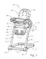
- the high chair can include a high chair structure 10 and a multiple tray system 30 (hereinafter also referred to as the "tray system 30").
- the high chair structure 10 includes a Z-shaped frame 11 that has a base portion 12 and a generally vertically extending upright portion 13 which meets the base portion 12 at an acute angle, and a seat member 20.
- the upright portion 13 includes a pair of laterally spaced base legs 17 for receiving respective telescopic legs 14 that can be optionally spring-biased to an extended position so as to offset the weight of the seat member 20 and a child that can be seated in the seat member 20.
- the base portion 12 is preferably equipped with a set of fixed wheels 19 at joints between the base portion 12 and the base legs 17 of the upright portion 13, and a pair of caster wheels 18 to provide mobility to the Z-shaped frame 11.
- the Z-shaped frame 11 supports the seat member 20 at an upper portion thereof.
- the seat member 20 is formed with a generally horizontal seat portion 22, which is surrounded on two lateral sides thereof by upright side walls 23 that form arm rests 23, and in the back between the arm rests 23 by a seat back 25.
- the front of the seat member 20 is open to accommodate the legs of a child seated on the seat portion 22, and is formed with a foot rest support 24 that extends downwardly from a forward edge of the seat portion 22.
- the foot rest support 24 is preferably formed with a plurality of vertically spaced pairs of horizontally oriented mounting slots 26 into which a foot rest 27 can be inserted for selective positioning according to the size of the child being supported on the seat member 20.
- the seat member 20 is supported on the Z-shaped frame 11, but is positioned such that the side wall 23, particularly along the back portion of the seat member 20, is spaced from the Z-shaped frame 11, which preferably curves from one telescopic leg 14 to the other.
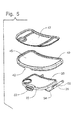
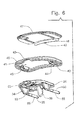
- the tray system 30 is generally formed of first and second tray members 32, 40, namely a small lower tray 32 that is mounted removably to the high chair structure 10, as will be described in greater detail below, and a larger upper tray 40, and an optional tray insert 47, which can be seen best in the exploded views of Figs. 5 and 6 .
- the lower tray 32 which can also be referred to as a travel tray since this smaller tray takes up less space when travelling than the larger upper tray 40, is sized to fit within a depression 41 formed into an underside of the upper tray 40.
- the underside of the upper tray 40 is provided with a pair of laterally spaced latch members 43 that are positioned to engage sides of the lower tray 32 so as to allow the upper tray 40 to be mounted on top of the lower tray 32.
- the latch members 43 are preferably slidable along the underside of the upper tray 40 so as to be movable between an outward release position and an inward engagement position.
- the latch members 43 project below the underside of the upper tray 40 so as to be engageable with the sides of the lower tray 32, and so that a top surface of the lower tray 32 will nest the larger upper tray 40.
- the upper tray 40 is only positioned a short distance above the lower tray 32 substantially equal to the thickness of the material forming the upper tray 40. Since the upper tray 40 does not incorporate a position adjustment mechanism that enables the upper tray 40 to be movable relative to the lower tray 32, the overall vertical height of the tray system 30 is minimized and is easier to manipulate with one hand.
- the latch members 43 are spring-biased into the inward engagement position such that the caregiver would need to grasp the latch members 43 on both sides and pull the latch members 43 outwardly so as to affect a release of the sides of the lower tray 32 and to enable removal of the upper tray 40 from the lower tray 32.
- the shape of each of the latch members 43 should be beveled along an interior side 44 thereof so that the upper tray 40 can be installed onto the lower tray 32 simply by positioning the upper tray 40 over the lower tray 32 and pressing downwardly thereon. The beveled interior sides 44 of the latch members 43 will cam the latch members 43 outwardly to allow the engagement thereof with the sides of the lower tray 32, with the spring bias closing the latch members 43 into the engagement position.
- the tray insert 47 can be placed onto the upper surface 45 of the upper tray 40, as is reflected in the exploded views of Figs. 5 and 6 , to provide a readily removable surface that can facilitate the cleaning of the upper tray 40.
- the tray insert 47 can be formed with a downwardly extending rear ledge 48 that incorporates a small retainer lip 49 at a center thereof.
- the tray insert 47 is sized to fit into the depressed upper surface 45 of the upper tray 40 with the rearward ledge 48 extending downwardly along a side surface of the upper tray 40 so that the retainer lip 49 can snap under the upper tray 40 and detachably secure the tray insert 47 on the upper tray 40.
- the tray insert 47 can be shaped to be compartmentalized, including a circular compartment for a cup, for example.
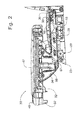
- the lower tray 32 is formed with a pair of laterally spaced, rearwardly extending, generally horizontal tray posts 35, each of which is shaped to fit into a socket 28 formed in an upper portion of a respective arm rest 23.
- Each of the tray posts 35 have a post body and a first anti-friction member 36, which, in this embodiment, is in a form of a first roller 36 mounted at a distal end of the post body and located along an upper surface of the post body so that the first roller 36 can engage a top surface of the socket 28 as the tray post 35 moves within the socket 28.
- the socket 28 of each of the arm rests 23 includes a socket body and a second anti-friction member 29, which, in this embodiment, is in the form of a second roller 29 built into the structure of the arm rest 23 on a lower surface of the socket body near the front end of the socket body, as can be seen best in Fig. 2 .
- the second roller 29 supports an underside of the post body of the respective tray post 35 as the respective tray post 35 moves within the socket body of the socket 28.
- the lower tray 32 is formed as a relatively flat tray member 33 with lateral legs 34 on opposing sides of the tray member 33 to elevate the tray member 33 above the tray posts 35 that extend rearwardly from the lateral legs 34.
- a central part of the lower tray 32 is formed with a retention horn member 39 that projects downwardly from the tray member 33 to restrict movement of a child placed on the seat member 20 when the tray system 30 is mounted to high chair structure 10.
- the retention horn member 39 is positionally adjustable with the lower tray 32 relative to the seat portion 22 of the seat member 20.
- the first and second rollers 36, 29 are preferred embodiments of the invention because the first and second rollers 36, 29 present rolling surfaces that essentially eliminate the friction problem between the tray posts 35 and the sockets 28.
- the first and second rollers 36, 29 can be replaced with other anti-friction members in other embodiments of the present invention.
- one or both of the first and second rollers 36, 29 could be replaced by an anti-friction post (not shown) formed of a wear resistant, low friction coefficient material, such as nylon or Teflon, that could slide in a corresponding anti-friction groove (not shown) formed in the top of the socket body of the socket 28 and the bottom of the post body of the tray post 35 to provide contact points between the tray post 35 and the socket 28 with minimal friction therebetween so as to facilitate positioning and adjustment of the tray assembly 30.
- an anti-friction post (not shown) formed of a wear resistant, low friction coefficient material, such as nylon or Teflon, that could slide in a corresponding anti-friction groove (not shown) formed in the top of the socket body of the socket 28 and the bottom of the post body of the tray post 35 to provide contact points between the tray post 35 and the socket 28 with minimal friction therebetween so as to facilitate positioning and adjustment of the tray assembly 30.
- first roller 36 is placed at the top of the distal end of the post body of the respective tray post 35, and the second roller 29 is located at the lower surface at the front of the socket body of the socket 28 of the respective arm rest 23 because the weight of the tray members (i.e., the lower tray 32, the upper tray 40) and the tray insert 47 is exerted through the lateral legs 34 to forward ends of the post bodies of the tray posts 35, which form a cantilevered arrangement when the tray posts 35 are mounted in the sockets 28.
- the tray members i.e., the lower tray 32, the upper tray 40
- the tray posts 35 are normally inclined within the sockets 28 so that the distal end of the post body of each of the tray posts 35 is pressed into the top surface of the socket 28 of the respective arm rest 23, and the tray posts 35 bear on the lower, front surface of the sockets 28.
- an upward force exerted on a front of the tray assembly 30 can cause some movements of the tray posts 35 within the sockets 28.
- an optional third roller (not shown) could be placed into a lower surface of the socket body of the socket 28 of each arm rest 23 at a selected location spaced rearwardly of the second roller 29 to provide additional support for the respective tray post 35 when the respective tray post 35 is received within the socket 28.
- the mounting of the larger upper tray 40 on the smaller lower tray 32 allows the entire tray system 30 to be positionally adjusted relative to the seat portion 22 to accommodate differently sized children.
- a position adjustment actuation mechanism 50 which will be described in greater detail below, allows the tray system 30 to be mounted onto the seat member 20 by simply aligning the tray posts 35 with the sockets 28 and inserting the tray posts 35 into the sockets 28 with a rearwardly directed force without manipulation of the position adjustment actuation mechanism 50. Accordingly, the tray system 30 can be placed onto the high chair structure 10 by the caregiver with a single hand, which is a significant advantage especially to a caregiver holding a child. Furthermore, not only is the position of the larger upper tray 40 adjustable, the position of the lower tray 32 can also be adjusted relative to the high chair structure 10.
- the position adjustment actuation mechanism 50 is housed in the lower tray 32, and includes an actuation member 52, which is in the form of an actuation button 52 in this embodiment, and which is located at the front of the lower tray 32 for convenient access thereto.
- the actuation button 52 projects outwardly from the lower tray 32 for a distance sufficient to accommodate the positioning of the larger upper tray 40 on top of the lower tray 32 such that when the upper tray 40 is positioned on top of the lower tray 32, a face of the actuation button 52 is substantially aligned with a forward edge of the upper tray 40.
- the upper tray 40 is formed with a corresponding notch 42 in the forward edge thereof to receive the actuation button 52.
- the lower surface of the socket 28 of each of the arm rests 23 is formed with a series of longitudinally spaced openings therein.
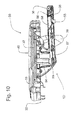
- a latch member 55 is pivotally mounted within a respective tray post 35 at the distal end thereof, and a tip of the latch member 55 projects out of the respective tray post 35, and is received in one of the openings in the socket 28 so as to be engaged therewith when the lower tray 32 is mounted to the seat member 20 of the high chair structure 10, where each opening corresponds to an adjusted position of the tray system 30 relative to the seat member 20.
- the pivoted latch member 55 is biased into engagement with the openings in the socket 28 by a spring 56 so that the lower tray 32 is retained in the selected position until a positive action is undertaken to release the latch member 55 from engagement with the opening in the socket 28.
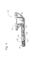
- the positive action to force the release of the latch member 55 from engagement with the opening in the lower surface of the socket 28 is provided by an actuation arm 57 that is mounted slidably within the respective tray post 35 for sliding movement in a fore-and-aft direction.
- the actuation arm 57 is formed with a cammed end 58 that is positioned to engage the latch member 55 and to force upward pivotal movement thereof against the biasing force exerted by the spring 56 when the actuation arm 57 is slid rearwardly.
- a forward portion of the actuation arm 57 is formed with an upwardly extending engagement member 59.
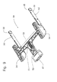
- the actuation button 52 is the forwardly extending portion of a slide link 53 that is mounted for longitudinal sliding movement underneath the lower tray 32, as can be seen best in Figs. 6 - 9 .
- the slide link 53 is T-shaped, and has laterally extending arms that terminate in engagement cups 54.
- Each engagement cup 54 captures the engagement member 59 of the respective actuation arm 57 within the respective tray post 35. Accordingly, the action of depressing the actuation button 52 causes the slide link 53 to move rearwardly underneath the lower tray 32, and, thus, affects a rearward movement of the engagement cups 54.
- each arm rest 23 adjacent the socket 28 is sloped upwardly and rearwardly to define a cam surface.
- the cam surface first gets into contact with the tip of the respective latch member 55, and then the latch member 55 is forced to pivot into the tray post 35 against the biasing force of the spring 56 due to contact with the sloped cam surface, so that the latch member 55 does not restrict the movement of the tray post 35 into the socket 28.
- each latch member 55 retracts into the respective tray post 35, slides over the second roller 29 until the tip of the latch member 55 becomes aligned with a first opening in the socket 28 of the respective arm rest 23, whereupon the spring 56 forces the latch member 55 to engage this opening and stops the rearward movement of the tray post 35 within the socket 28.
- a forward side of the tip of each latch member 55 is squared off so that forward longitudinal forces exerted onto the tray system 30 do not cause a cam action that pops the tip of the latch member 55 out of engagement with the selected opening in the socket 28 of the respective arm rest 23.
- a rearward side of the tip of each latch member 55 is formed with an acute back angle to prevent rearward longitudinal forces from causing the latch member 55 to pop out of engagement with the selected opening in the socket 28 of the respective arm rest 23.
Landscapes
- Chair Legs, Seat Parts, And Backrests (AREA)
- Carriages For Children, Sleds, And Other Hand-Operated Vehicles (AREA)
- Seats For Vehicles (AREA)
- Accommodation For Nursing Or Treatment Tables (AREA)
- Chairs For Special Purposes, Such As Reclining Chairs (AREA)
- Special Chairs (AREA)
Applications Claiming Priority (2)
| Application Number | Priority Date | Filing Date | Title |
|---|---|---|---|
| US6630908P | 2008-02-19 | 2008-02-19 | |
| EP09153127.7A EP2092858B1 (en) | 2008-02-19 | 2009-02-18 | Tray system for child's high chair |
Related Parent Applications (2)
| Application Number | Title | Priority Date | Filing Date |
|---|---|---|---|
| EP09153127.7A Division-Into EP2092858B1 (en) | 2008-02-19 | 2009-02-18 | Tray system for child's high chair |
| EP09153127.7 Division | 2009-02-18 |
Publications (1)
| Publication Number | Publication Date |
|---|---|
| EP2606773A1 true EP2606773A1 (en) | 2013-06-26 |
Family
ID=40821747
Family Applications (3)
| Application Number | Title | Priority Date | Filing Date |
|---|---|---|---|
| EP13154829.9A Withdrawn EP2606773A1 (en) | 2008-02-19 | 2009-02-18 | Tray system for child's high chair |
| EP09153125.1A Active EP2092857B1 (en) | 2008-02-19 | 2009-02-18 | High chair with a tray latch mechanism |
| EP09153127.7A Active EP2092858B1 (en) | 2008-02-19 | 2009-02-18 | Tray system for child's high chair |
Family Applications After (2)
| Application Number | Title | Priority Date | Filing Date |
|---|---|---|---|
| EP09153125.1A Active EP2092857B1 (en) | 2008-02-19 | 2009-02-18 | High chair with a tray latch mechanism |
| EP09153127.7A Active EP2092858B1 (en) | 2008-02-19 | 2009-02-18 | Tray system for child's high chair |
Country Status (4)
| Country | Link |
|---|---|
| US (2) | US8201879B2 (cg-RX-API-DMAC7.html) |
| EP (3) | EP2606773A1 (cg-RX-API-DMAC7.html) |
| JP (3) | JP5129177B2 (cg-RX-API-DMAC7.html) |
| CN (3) | CN101912209B (cg-RX-API-DMAC7.html) |
Cited By (1)
| Publication number | Priority date | Publication date | Assignee | Title |
|---|---|---|---|---|
| USD1045515S1 (en) | 2022-01-05 | 2024-10-08 | Kids2, Inc. | Snack tray |
Families Citing this family (45)
| Publication number | Priority date | Publication date | Assignee | Title |
|---|---|---|---|---|
| US8201879B2 (en) * | 2008-02-19 | 2012-06-19 | Wonderland Nurserygoods Co., Ltd | Tray system for child's high chair |
| TWI417071B (zh) * | 2010-11-04 | 2013-12-01 | Bp Childrens Prod Hk Co Ltd | 可拆卸腳踏板之幼兒高腳椅 |
| JP2012096000A (ja) * | 2010-11-04 | 2012-05-24 | Bp Children's Products Hk Co Ltd | 取り外し可能なフットレストを有する子供椅子 |
| CN102599764A (zh) * | 2011-01-21 | 2012-07-25 | 明门香港股份有限公司 | 组合式餐盘 |
| US20160270542A1 (en) * | 2011-07-22 | 2016-09-22 | Robert Foster | Spectator Tray |
| US9039079B2 (en) * | 2012-04-12 | 2015-05-26 | Mattel, Inc. | Children's tray with placement indicator |
| CN202919645U (zh) * | 2012-05-02 | 2013-05-08 | 中山市隆成日用制品有限公司 | 婴童椅具的背靠调整机构 |
| US8696055B2 (en) * | 2012-09-14 | 2014-04-15 | Helen Of Troy Limited | Highchair with adjustable tray and seat height |
| KR101412975B1 (ko) * | 2012-10-05 | 2014-06-27 | 김진성 | 하드케이스 가방형태의 유아 놀이용 멀티 트레이 |
| CN103126422B (zh) * | 2013-03-08 | 2015-02-18 | 昆山小小恐龙儿童用品有限公司 | 一种分离式儿童餐盘 |
| CN104337282B (zh) * | 2013-07-31 | 2017-08-08 | 明门香港股份有限公司 | 儿童座椅及其扶手调整装置 |
| USD742657S1 (en) | 2013-09-18 | 2015-11-10 | Graco Children's Products, Inc. | High chair |
| US9565929B2 (en) | 2013-10-17 | 2017-02-14 | Regalo International, Llc | Dine and draw child lap tray apparatus |
| US9895005B2 (en) | 2014-05-21 | 2018-02-20 | Kids Ii, Inc. | Convertible child seat |
| US9560919B2 (en) * | 2014-08-01 | 2017-02-07 | Thorley Industries Llc | Infant chairs |
| US11877671B2 (en) | 2015-04-25 | 2024-01-23 | Kids2, Inc. | Convertible high chair |
| US10588424B2 (en) | 2015-04-25 | 2020-03-17 | Kids2, Inc. | Convertible high chair |
| US20160309909A1 (en) * | 2015-04-25 | 2016-10-27 | Kids Ii, Inc. | Child support device |
| US11723477B2 (en) | 2015-04-25 | 2023-08-15 | Kids2, Inc. | Convertible highchair |
| USD781059S1 (en) | 2015-11-24 | 2017-03-14 | Mattel, Inc. | Infant support structure |
| USD873503S1 (en) | 2016-04-04 | 2020-01-21 | Macneil Ip Llc | Pet feeding system |
| USD894498S1 (en) | 2016-04-04 | 2020-08-25 | Macneil Ip Llc | Single-bowl pet water/food station |
| USD887650S1 (en) * | 2016-04-04 | 2020-06-16 | Macneil Ip Llc | Pet water station |
| USD802853S1 (en) * | 2016-04-04 | 2017-11-14 | Macneil Ip Llc | Pet feeding system |
| USD873502S1 (en) | 2016-04-04 | 2020-01-21 | Macneil Ip Llc | Double bowl low-profile pet feeding station |
| USD873504S1 (en) | 2016-04-04 | 2020-01-21 | Macneil Ip Llc | Compact mat for pet feeding system |
| US10561254B2 (en) * | 2017-04-04 | 2020-02-18 | Wonderland Switzerland Ag | Child tray assembly and multi-function high chair |
| DE102018204778B4 (de) | 2017-04-04 | 2019-06-27 | Wonderland Switzerland Ag | Multifunktioneller Hochstuhl |
| CN107928246A (zh) * | 2017-11-28 | 2018-04-20 | 好孩子儿童用品有限公司 | 儿童餐椅 |
| US10709259B2 (en) * | 2018-03-05 | 2020-07-14 | Wonderland Switzerland Ag | Latch mechanism and tray assembly |
| US10588425B1 (en) * | 2018-06-08 | 2020-03-17 | Angelica Jordan | Child seat system |
| CN108784128A (zh) * | 2018-06-21 | 2018-11-13 | 东莞市鸿福物业管理服务有限公司 | 多用途婴儿高脚椅 |
| US20200156279A1 (en) * | 2018-11-16 | 2020-05-21 | Corvesco Co. Ltd. | Cutting tool latch assembly |
| US11166570B1 (en) | 2019-03-19 | 2021-11-09 | Regalo International, Llc | High chair apparatus with wide foot print |
| US11641952B2 (en) | 2019-06-21 | 2023-05-09 | Kids2, Inc. | Modular cradle |
| USD880788S1 (en) * | 2019-08-19 | 2020-04-07 | David H. Price | Mat |
| USD880787S1 (en) * | 2019-08-19 | 2020-04-07 | David H. Price | Mat |
| US11589682B2 (en) | 2019-09-19 | 2023-02-28 | Thorley Industries, Llc | Infant chairs |
| USD979259S1 (en) | 2020-09-17 | 2023-02-28 | Kids2, Inc. | Modular swing |
| USD958897S1 (en) | 2020-09-17 | 2022-07-26 | Kids2, Inc. | Modular toy bar |
| USD977865S1 (en) | 2020-09-17 | 2023-02-14 | Kids2, Inc. | Modular cradle |
| CN112704355B (zh) * | 2020-12-29 | 2024-07-09 | 宁波华盛塑胶制品股份有限公司 | 餐盘组件的装配结构及儿童餐椅 |
| CN113229676B (zh) * | 2021-06-24 | 2024-12-20 | 杭州闪电兔智能科技有限公司 | 一种儿童使用的餐椅 |
| CN220069303U (zh) * | 2023-04-07 | 2023-11-24 | 厦门梦贝比儿童用品有限公司 | 一种多用途儿童餐椅 |
| USD1101218S1 (en) | 2024-09-18 | 2025-11-04 | Essential Skills, PLC | Foot stool for kids |
Citations (9)
| Publication number | Priority date | Publication date | Assignee | Title |
|---|---|---|---|---|
| US2767774A (en) * | 1952-03-13 | 1956-10-23 | George T Derby | High chair with tray attachment |
| JPS6366968U (cg-RX-API-DMAC7.html) * | 1986-10-22 | 1988-05-06 | ||
| EP0387764A1 (en) * | 1989-03-15 | 1990-09-19 | CAM IL MONDO DEL BAMBINO S.p.A. | Baby's high-chair with foldable structure |
| WO1997016996A1 (en) * | 1995-11-09 | 1997-05-15 | Graco Children's Products, Inc. | Improved high chair system |
| US6416124B1 (en) * | 2000-06-02 | 2002-07-09 | Link Treasure Limited | Highchair with horizontally adjustable tray |
| US6419312B1 (en) * | 2000-10-27 | 2002-07-16 | Regalo International, Llc | Incrementally slidable high chair tray with quick release |
| US6497452B2 (en) | 2000-11-17 | 2002-12-24 | Artsana, S.P.A. | High-chair with tray provided with removable cover element |
| US20050146168A1 (en) * | 2003-03-26 | 2005-07-07 | Graco Children's Products Inc. | High chair |
| US7261370B1 (en) * | 2004-12-03 | 2007-08-28 | Whitesell Jr Robert C | High chair apparatus |
Family Cites Families (30)
| Publication number | Priority date | Publication date | Assignee | Title |
|---|---|---|---|---|
| US1505518A (en) * | 1922-07-12 | 1924-08-19 | Jr Samuel T Workman | High chair |
| US1859150A (en) | 1931-03-31 | 1932-05-17 | Joseph V Moran | Baby chair |
| US2115860A (en) * | 1937-05-21 | 1938-05-03 | Kroll Samuel | Latch for high chair tables |
| US2440224A (en) * | 1945-03-26 | 1948-04-20 | Nat Lock Co | High chair tray slide |
| US3239255A (en) * | 1964-04-06 | 1966-03-08 | Charles E Murcott | One directional movement catch device |
| US3580631A (en) * | 1969-02-10 | 1971-05-25 | Lumex | Invalid chair |
| US3635522A (en) * | 1969-09-29 | 1972-01-18 | Kerwit Medical Products Inc | Surgical treatment method and apparatus |
| JPH0336311Y2 (cg-RX-API-DMAC7.html) * | 1985-08-14 | 1991-08-01 | ||
| US4632451A (en) * | 1986-02-10 | 1986-12-30 | Lee Henry D | Wheelchair table and desk attachments |
| US4807928A (en) * | 1987-09-18 | 1989-02-28 | Gerico, Inc. | Tray apparatus for use with a chair |
| JPH0339091Y2 (cg-RX-API-DMAC7.html) * | 1988-12-27 | 1991-08-16 | ||
| US5238292A (en) * | 1991-09-04 | 1993-08-24 | Gerry Baby Products Company | Highchair with adjustable seat |
| DE9212161U1 (de) * | 1992-08-06 | 1993-01-21 | Kuo, Tzu-Yu, Tainan | Stuhl für Kleinkinder |
| US5489138A (en) * | 1993-10-01 | 1996-02-06 | Lisco, Inc. | Height adjustable high chair |
| US5468043A (en) * | 1994-08-16 | 1995-11-21 | Jina Manufacturer Thai Co., Ltd. | Foldable chair |
| US5527090A (en) * | 1994-11-04 | 1996-06-18 | Cosco, Inc. | Child seat tray assembly |
| US6293623B1 (en) * | 1997-09-26 | 2001-09-25 | Cosco Management, Inc. | Juvenile seat assembly |
| US6347833B1 (en) * | 2000-09-11 | 2002-02-19 | Trident Company Ltd. | High chair having a seat-tilting mechanism |
| US20020036416A1 (en) * | 2000-09-22 | 2002-03-28 | Andrew Mendenhall | Multi-piece accessory tray |
| DE20019014U1 (de) * | 2000-11-08 | 2001-02-15 | Cheng, Kenny, Taipeh/T'ai-pei | Verriegelungsvorrichtung für einen Anbautisch |
| US6511124B2 (en) * | 2001-01-23 | 2003-01-28 | Mark Ellis Combs | Tray table for a child's car seat and associated methods |
| CN2484828Y (zh) | 2001-06-22 | 2002-04-10 | 李绍汉 | 快速嵌装的抽屉 |
| US6920830B1 (en) * | 2001-09-18 | 2005-07-26 | Mattel, Inc. | Removable tray insert and tray set |
| JP4014385B2 (ja) * | 2001-10-16 | 2007-11-28 | 北川木工販売株式会社 | 幼児用椅子 |
| JP2005027764A (ja) * | 2003-07-09 | 2005-02-03 | Showa Prod:Kk | 折り畳み式テーブル、引出し式椅子及び椅子付テーブル |
| US7328941B2 (en) * | 2004-04-30 | 2008-02-12 | Mattel, Inc. | Infant support with selectively covered tray |
| TWM258666U (en) * | 2004-05-13 | 2005-03-11 | Huei-Min Jhou | A multi-functional dining chair for children |
| CN2794336Y (zh) * | 2005-01-31 | 2006-07-12 | 上海统资电器有限公司 | 幼童高脚椅的高度调节器结构 |
| CN2907410Y (zh) * | 2006-06-13 | 2007-06-06 | 明门实业股份有限公司 | 具有锁定装置的可收合高脚椅 |
| US8201879B2 (en) * | 2008-02-19 | 2012-06-19 | Wonderland Nurserygoods Co., Ltd | Tray system for child's high chair |
-
2009
- 2009-02-07 US US12/367,514 patent/US8201879B2/en active Active
- 2009-02-07 US US12/367,516 patent/US7922244B2/en active Active
- 2009-02-17 JP JP2009034067A patent/JP5129177B2/ja active Active
- 2009-02-18 JP JP2009035226A patent/JP5468791B2/ja active Active
- 2009-02-18 CN CN2010102292379A patent/CN101912209B/zh active Active
- 2009-02-18 EP EP13154829.9A patent/EP2606773A1/en not_active Withdrawn
- 2009-02-18 EP EP09153125.1A patent/EP2092857B1/en active Active
- 2009-02-18 CN CNA200910009333XA patent/CN101513310A/zh active Pending
- 2009-02-18 CN CN2009100093344A patent/CN101558947B/zh active Active
- 2009-02-18 EP EP09153127.7A patent/EP2092858B1/en active Active
-
2012
- 2012-08-21 JP JP2012182110A patent/JP5524297B2/ja active Active
Patent Citations (10)
| Publication number | Priority date | Publication date | Assignee | Title |
|---|---|---|---|---|
| US2767774A (en) * | 1952-03-13 | 1956-10-23 | George T Derby | High chair with tray attachment |
| JPS6366968U (cg-RX-API-DMAC7.html) * | 1986-10-22 | 1988-05-06 | ||
| EP0387764A1 (en) * | 1989-03-15 | 1990-09-19 | CAM IL MONDO DEL BAMBINO S.p.A. | Baby's high-chair with foldable structure |
| WO1997016996A1 (en) * | 1995-11-09 | 1997-05-15 | Graco Children's Products, Inc. | Improved high chair system |
| US5810432A (en) | 1995-11-09 | 1998-09-22 | Graco Children's Products Inc. | High chair system |
| US6416124B1 (en) * | 2000-06-02 | 2002-07-09 | Link Treasure Limited | Highchair with horizontally adjustable tray |
| US6419312B1 (en) * | 2000-10-27 | 2002-07-16 | Regalo International, Llc | Incrementally slidable high chair tray with quick release |
| US6497452B2 (en) | 2000-11-17 | 2002-12-24 | Artsana, S.P.A. | High-chair with tray provided with removable cover element |
| US20050146168A1 (en) * | 2003-03-26 | 2005-07-07 | Graco Children's Products Inc. | High chair |
| US7261370B1 (en) * | 2004-12-03 | 2007-08-28 | Whitesell Jr Robert C | High chair apparatus |
Cited By (1)
| Publication number | Priority date | Publication date | Assignee | Title |
|---|---|---|---|---|
| USD1045515S1 (en) | 2022-01-05 | 2024-10-08 | Kids2, Inc. | Snack tray |
Also Published As
| Publication number | Publication date |
|---|---|
| JP5129177B2 (ja) | 2013-01-23 |
| CN101912209A (zh) | 2010-12-15 |
| US20090206638A1 (en) | 2009-08-20 |
| EP2092857A3 (en) | 2012-03-28 |
| JP5468791B2 (ja) | 2014-04-09 |
| JP2009195696A (ja) | 2009-09-03 |
| EP2092858A2 (en) | 2009-08-26 |
| JP2012223624A (ja) | 2012-11-15 |
| CN101513310A (zh) | 2009-08-26 |
| JP2009195698A (ja) | 2009-09-03 |
| US8201879B2 (en) | 2012-06-19 |
| CN101558947B (zh) | 2013-01-23 |
| EP2092858A3 (en) | 2012-03-28 |
| US7922244B2 (en) | 2011-04-12 |
| CN101912209B (zh) | 2012-05-09 |
| EP2092858B1 (en) | 2018-05-30 |
| EP2092857B1 (en) | 2013-11-20 |
| US20090206639A1 (en) | 2009-08-20 |
| JP5524297B2 (ja) | 2014-06-18 |
| EP2092857A2 (en) | 2009-08-26 |
| CN101558947A (zh) | 2009-10-21 |
Similar Documents
| Publication | Publication Date | Title |
|---|---|---|
| EP2092858B1 (en) | Tray system for child's high chair | |
| US8651572B2 (en) | Swivel feeding seat | |
| US5507550A (en) | Highchair | |
| EP2206453B1 (en) | Dual purpose high chair | |
| EP2765887B1 (en) | Highchair with adjustable tray and seat height | |
| CN103003097B (zh) | 斗形座椅形式的婴儿提篮 | |
| US20050006930A1 (en) | High chair | |
| EP2615946B1 (en) | Adjustable booster seat | |
| US7201445B1 (en) | Feeding seat | |
| FR2702639A3 (fr) | Chaise haute pour bébé réglable en hauteur. |
Legal Events
| Date | Code | Title | Description |
|---|---|---|---|
| AC | Divisional application: reference to earlier application |
Ref document number: 2092858 Country of ref document: EP Kind code of ref document: P |
|
| AK | Designated contracting states |
Kind code of ref document: A1 Designated state(s): AT BE BG CH CY CZ DE DK EE ES FI FR GB GR HR HU IE IS IT LI LT LU LV MC MK MT NL NO PL PT RO SE SI SK TR |
|
| PUAI | Public reference made under article 153(3) epc to a published international application that has entered the european phase |
Free format text: ORIGINAL CODE: 0009012 |
|
| RIN1 | Information on inventor provided before grant (corrected) |
Inventor name: HARTENSHINE, CURTIS M. Inventor name: BEARUP, ADAM D. |
|
| 17P | Request for examination filed |
Effective date: 20131223 |
|
| RBV | Designated contracting states (corrected) |
Designated state(s): AT BE BG CH CY CZ DE DK EE ES FI FR GB GR HR HU IE IS IT LI LT LU LV MC MK MT NL NO PL PT RO SE SI SK TR |
|
| 17Q | First examination report despatched |
Effective date: 20160721 |
|
| STAA | Information on the status of an ep patent application or granted ep patent |
Free format text: STATUS: EXAMINATION IS IN PROGRESS |
|
| STAA | Information on the status of an ep patent application or granted ep patent |
Free format text: STATUS: THE APPLICATION IS DEEMED TO BE WITHDRAWN |
|
| 18D | Application deemed to be withdrawn |
Effective date: 20170201 |