EP2092857B1 - High chair with a tray latch mechanism - Google Patents
High chair with a tray latch mechanism Download PDFInfo
- Publication number
- EP2092857B1 EP2092857B1 EP09153125.1A EP09153125A EP2092857B1 EP 2092857 B1 EP2092857 B1 EP 2092857B1 EP 09153125 A EP09153125 A EP 09153125A EP 2092857 B1 EP2092857 B1 EP 2092857B1
- Authority
- EP
- European Patent Office
- Prior art keywords
- tray
- high chair
- socket
- posts
- lock pin
- Prior art date
- Legal status (The legal status is an assumption and is not a legal conclusion. Google has not performed a legal analysis and makes no representation as to the accuracy of the status listed.)
- Active
Links
- 238000004140 cleaning Methods 0.000 abstract description 3
- 238000003780 insertion Methods 0.000 abstract description 3
- 230000037431 insertion Effects 0.000 abstract description 3
- 235000011888 snacks Nutrition 0.000 description 9
- 239000000463 material Substances 0.000 description 4
- 230000000994 depressogenic effect Effects 0.000 description 3
- 230000014759 maintenance of location Effects 0.000 description 3
- 230000001154 acute effect Effects 0.000 description 2
- 230000000881 depressing effect Effects 0.000 description 2
- 238000009434 installation Methods 0.000 description 2
- 230000008092 positive effect Effects 0.000 description 2
- 239000004677 Nylon Substances 0.000 description 1
- 239000004809 Teflon Substances 0.000 description 1
- 229920006362 Teflon® Polymers 0.000 description 1
- 230000001419 dependent effect Effects 0.000 description 1
- 235000013305 food Nutrition 0.000 description 1
- 230000008450 motivation Effects 0.000 description 1
- 229920001778 nylon Polymers 0.000 description 1
- 230000000717 retained effect Effects 0.000 description 1
- 238000005096 rolling process Methods 0.000 description 1
Images


Classifications
-
- A—HUMAN NECESSITIES
- A47—FURNITURE; DOMESTIC ARTICLES OR APPLIANCES; COFFEE MILLS; SPICE MILLS; SUCTION CLEANERS IN GENERAL
- A47D—FURNITURE SPECIALLY ADAPTED FOR CHILDREN
- A47D1/00—Children's chairs
- A47D1/008—Children's chairs with trays
- A47D1/0081—Children's chairs with trays adjustable
-
- A—HUMAN NECESSITIES
- A47—FURNITURE; DOMESTIC ARTICLES OR APPLIANCES; COFFEE MILLS; SPICE MILLS; SUCTION CLEANERS IN GENERAL
- A47D—FURNITURE SPECIALLY ADAPTED FOR CHILDREN
- A47D1/00—Children's chairs
- A47D1/002—Children's chairs adjustable
-
- A—HUMAN NECESSITIES
- A47—FURNITURE; DOMESTIC ARTICLES OR APPLIANCES; COFFEE MILLS; SPICE MILLS; SUCTION CLEANERS IN GENERAL
- A47D—FURNITURE SPECIALLY ADAPTED FOR CHILDREN
- A47D1/00—Children's chairs
- A47D1/002—Children's chairs adjustable
- A47D1/004—Children's chairs adjustable in height
-
- A—HUMAN NECESSITIES
- A47—FURNITURE; DOMESTIC ARTICLES OR APPLIANCES; COFFEE MILLS; SPICE MILLS; SUCTION CLEANERS IN GENERAL
- A47D—FURNITURE SPECIALLY ADAPTED FOR CHILDREN
- A47D1/00—Children's chairs
- A47D1/008—Children's chairs with trays
- A47D1/0085—Children's chairs with trays removable
Definitions
- the present invention relates to a child's high chair having a tray system with a latch mechanism that permits easy installation of the tray system while providing positional adjustment.
- High chairs can incorporate height adjustment mechanism so that the seat can be vertically positioned to fit various table heights so that the tray mechanism could be removed from the high chair and the child positioned on the high chair be pushed up to a table.
- High chairs can provide different tray options. Some high chair configurations provide a smaller snack tray under the typical large high chair tray. These snack trays are attached to the high chair seat and do not have the ability to be adjusted in and out to accommodate different child sizes. Furthermore, since the snack tray is directly attached to the high chair seat, the caregiver is required to lift the child up and over the snack tray in order to seat the child in the high chair, or to remove the child from the high chair. Although some snack trays can be removed from the high chair seat without tools, the removal of the snack tray typically requires two hands and the snack tray is usually only removed when the high chair is being used without the large tray, such as when the child in the high chair is pushed directly up to the table. While the snack tray is not typically adjustable positionally, the large tray is usually positionally adjustable on the snack tray.
- the post and socket design can be advantageous over other tray mounting designs in that the tray is easy to align when fastening to the high chair seat and the tray offers a strong interlocking connection with the high chair structure to withstand extreme cases of abuse during product use. Even so, the post and socket design is not without drawbacks.
- the post and socket tray mounting design typically suffers fromhigh amounts of friction between post and socket and from the need to actuate the tray adjustment mechanism before for connecting the tray to the high chair seat.
- the friction problem is typically resolved in a limited manner by using dissimilar materials for the tray post and high chair socket components. While dissimilar materials do aid in reducing the friction problem, the post and socket mounting trays often remain difficult to adjust positionally relative to the high chair as the tray posts often bind or stick. The caregiver can become frustrated and loose motivation for removing the tray altogether. As a result, the value of having a removable tray can be unrealized or under appreciated by the caregiver.
- tray latching mechanism enables the tray to adjust the position of the tray relative to the high chair and to be located back at the same selected position each time the tray is removed from the high chair.
- the tray latching mechani sm is actuated by pulling a central front actuation handle to adjust the tray position related to the high chair and by pushing the handle to remove the tray from or mount the tray onto the high chair armrests.
- U. S. Patent No. 5,238,292 granted on August 24, 1993, to Douglas Golenz, et al , also teaches a front, centrally positioned actuator lever that operates a latch mechanism for a removable high chair tray through several linkages that affect rotation of a central member to operate laterally positioned engagement members such that the pulling of the central lever releases the engagement of the tray with the high chair arm rests.
- the front, central actuation member in the high chair tray in U. S. Patent No. 5, 348, 374 granted to Tzu-Yu Kuo on September 20, 1994 , slides a cam actuator into laterally extending actuator arms to operate engagement members on the lateral sides of the tray apparatus.
- U. S. Patent No. 5,489,138 Another centrally mounted actuator lever that moves a linkage to cause a latching and unlatching operation for the tray is shown in U. S. Patent No. 5,489,138, issued to John Mariol, et al on February 6, 1996 .
- the actuated linkage engages recesses formed in the sides of the arm rests of the high chair to provide a fore-and-aft adjustment feature for the tray.
- U. S. Patent No. 6,416,124 discloses a highchair having a central actuator operable to move horizontal and vertical components underneath the tray, and a pair-of supports on opposite sides of the high chair, each having a plurality of elastic projections on the inside and a movable tray coupled between the supports.
- the supports further comprise a tube disposed on a leg of the high chair and a plurality of studs releasably coupled to the highchair.
- WO96/13999 discloses a child seat tray assembly including a mounting-latch including a catch for engaging an undercut of a passageway formed in a tray mount of an arm of a high chair.
- US2440224 discloses a high chair tray slide.
- None of the cited prior art shows a latch mechanism, or a position adjustment mechanism, that would allow a one-handed insertion of a tray onto the structure of a high chair, without requiring the manipulation of the latch mechanism to affect the mounting of horizontally extending tray posts into corresponding sockets. It would be desirable to provide a latch mechanism for a high chair tray structure that will allow an easy positioning of the tray on the high chair and provide improved flexibility in the use of the tray.
- the present invention provides a high chair, as defined in claim 1.
- Optional features are recited in the dependent claims.
- the tray post incorporates a latch member that projects below the tray post for engagement with openings in a bottom surface of the socket to positionally secure the tray system in a selected position on the high chair structure.
- retractable latch member allows installation of the tray system onto the high chair structure without requiring manipulation of the latch mechanism.
- the latch member pivots into engagement with a first opening in the bottom surface of the socket to latch the tray system into position after being passively inserted into the arm rest.
- positional adjustment of the tray system requires manipulation of the latch mechanism only after the tray system has been mounted onto the high chair structure.
- the tray system requires manipulation of the latch mechanism to dismount the tray system from the high chair structure.
- the latch mechanism includes an actuation button centrally positioned at the front of the tray system.
- the actuation button is conveniently accessible by a caregiver for operation using a single hand.
- the actuation button moves a slide member positioned underneath the tray system to branch laterally for operation of a linkage housed within each of the tray posts.
- each of the actuation linkages in the tray posts includes a slidable actuation arm engaged with a central slide member underneath the tray system.
- the centrally positioned actuation button is operable to move simultaneously the actuation arms in the opposing tray posts.
- each of the slidable actuation arms includes a cam surface to cause pivotal movement of the latch member when moved into engagement with the latch member so as to affect a release of the latch member from the selected one of the openings in the socket of the arm rest.
- the latch mechanism of the high chair includes a central, front actuation button that moves a slide link mounted underneath the tray system.
- the slide link is connected to an actuation arm slidably mounted within each respective tray post.
- the actuation arm includes a cam surface that pivots a latch member having a rectangular lock pin that extends below the tray post into engagement with a selected one of openings in the socket receiving the tray post.
- the latch member is spring-loaded into engagement with the selected opening in the socket.
- a front surface of a respective arm rest of a high chair structure is sloped to cam the lock pin into the tray post so as to permit a passive mounting of the tray system onto the high chair structure, but it requires a non-passive manipulation to affect positional adjustment or removal once the lock pin is engaged with one of the openings.
- the high chair includes a high chair structure 10 and a multiple tray system 30 (hereinafter also referred to as the "tray system 30").
- the high chair structure 10 includes a Z-shaped frame 11 that has a base portion 12 and a generally vertically extending upright portion 13 which meets the base portion 12 at an acute angle, and a seat member 20.
- the upright portion 13 includes a pair of laterally spaced base legs 17 for receiving respective telescopic legs 14 that can be optionally spring-biased to an extended position so as to offset the weight of the seat member 20 and a child that can be seated in the seat member 20.
- the base portion 12 is preferably equipped with a set of fixed wheels 19 at joints between the base portion 12 and the base legs 17 of the upright portion 13, and a pair of caster wheels 18 to provide mobility to the Z-shaped frame 11.
- the Z-shaped frame 11 supports the seat member 20 at an upper portion thereof.
- the seat member 20 is formed with a generally horizontal seat portion 22, which is surrounded on two lateral sides thereof by upright side walls 23 that form arm rests 23, and in the back between the arm rests 23 by a seat back 25.
- the front of the seat member 20 is open to accommodate the legs of a child seated on the seat portion 22, and is formed with a foot rest support 24 that extends downwardly from a forward edge of the seat portion 22.
- the foot rest support 24 is preferably formed with a plurality of vertically spaced pairs of horizontally oriented mounting slots 26 into which a foot rest 27 can be inserted for selective positioning according to the size of the child being supported on the seat member 20.
- the seat member 20 is supported on the Z-shaped frame 11, but is positioned such that the side wall 23, particularly along the back portion of the seat member 20, is spaced from the Z-shaped frame 11, which preferably curves from one telescopic leg 14 to the other.
- the tray system 30 is generally formed of first and second tray members 32, 40, namely a small lower tray 32 that is mounted removably to the high chair structure 10, as will be described in greater detail below, and a larger upper tray 40, and an optional tray insert 47, which can be seen best in the exploded views of Figs. 5 and 6 .
- the lower tray 32 which can also be referred to as a travel tray since this smaller tray takes up less space when traveling than the larger upper tray 40, is sized to fit within a depression 41 formed into an underside of the upper tray 40.
- the underside of the upper tray 40 is provided with a pair of laterally spaced latch members 43 that are positioned to engage sides of the lower tray 32 so as to allow the upper tray 40 to be mounted on top of the lower tray 32.
- the latch members 43 are preferably slidable along the underside of the upper tray 40 so as to be movable between an outward release position and an inward engagement position.
- the latch members 43 project below the underside of the upper tray 40 so as to be engageable with the sides of the lower tray 32, and so that a top surface of the lower tray 32 will nest the larger upper tray 40.
- the upper tray 40 is only positioned a short distance above the lower tray 32 substantially equal to the thickness of the material forming the upper tray 40. Since the upper tray 40 does not incorporate a position adjustment mechanism that enables the upper tray 40 to be movable relative to the lower tray 32, the overall vertical height of the tray system 30 is minimized and is easier to manipulate with one hand.
- the latch members 43 are spring-biased into the inward engagement position such that the caregiver would need to grasp the latch members 43 on both sides and pull the latch members 43 outwardly so as to affect a release of the sides of the lower tray 32 and to enable removal of the upper tray 40 from the lower tray 32.
- the shape of each of the latch members 43 should be beveled along an interior side 44 thereof so that the upper tray 40 can be installed onto the lower tray 32 simply by positioning the upper tray 40 over the lower tray 32 and pressing downwardly thereon. The beveled interior sides 44 of the latch members 43 will cam the latch members 43 outwardly to allow the engagement thereof with the sides of the lower tray 32, with the spring bias closing the latch members 43 into the engagement position.
- the tray insert 47 can be placed onto the upper surface 45 of the upper tray 40, as is reflected in the exploded views of Figs. 5 and 6 , to provide a readily removable surface that can facilitate cleaning of the upper tray 40.
- the tray insert 47 can be formed with a downwardly extending rear ledge 48 that incorporates a small retainer lip 49 at a center thereof.
- the tray insert 47 is sized to fit into the depressed upper surface 45 of the upper tray 40 with the rearward ledge 48 extending downwardly along a side surface of the upper tray 40 so that the retainer lip 49 can snap under the upper tray 40 and detachably secure the tray insert 47 on the upper tray 40.
- the tray insert 47 can be shaped to be compartmentalized, including a circular compartment for a cup, for example.
- the lower tray 32 is formed with a pair of laterally spaced, rearwardly extending, generally horizontal tray posts 35, each of which is shaped to fit into a socket 28 formed in an upper portion of a respective arm rest 23.
- Each of the tray posts 35 have a post body and a first anti-friction member 36, which, in this embodiment, is in a form of a first roller 36 mounted at a distal end of the post body and located along an upper surface of the post body so that the first roller 36 can engage a top surface of the socket 28 as the tray post 35 moves within the socket 28.
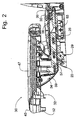
- the socket 28 of each of the arm rests 23 includes a socket body and a second anti-friction member 29, which, in this embodiment, is in the form of a second roller 29 built into the structure of the arm rest 23 on a lower surface of the socket body near the front end of the socket body, as can be seen best in Fig. 2 .
- the second roller 29 supports an underside of the post body of the respective tray post 35 as the respective tray post 35 moves within the socket body of the socket 28.
- the lower tray 32 is formed as a relatively flat tray member 33 with lateral legs 34 on opposing sides of the tray member 33 to elevate the tray member 33 above the tray posts 35 that extend rearwardly from the lateral legs 34.
- a central part of the lower tray 32 is formed with a retention horn member 39 that projects downwardly from the tray member 33 to restrict movement of a child placed on the seat member 20 when the tray system 30 is mounted to the high chair structure 10.
- the retention horn member 39 is positionally adjustable with the lower tray 32 relative to the seat portion 22 of the seat member 20.
- the first and second rollers 36, 29 are preferred embodiments of the invention because the first and second rollers 36, 29 present rolling surfaces that essentially eliminate the friction problem between the tray posts 35 and the sockets 28.
- the first and second rollers 36, 29 could be replaced by other anti-friction posts (not shown) formed of a wear resistant, low friction coefficient material, such as nylon or Teflon, that could slide in a corresponding anti-friction groove (not shown) formed in the top of the socket body of the socket 28 and the bottom of the post body of the tray post 35 to provide contact points between the tray post 35 and the socket 28 with minimal friction therebetween so as to facilitate positioning and adjustment of the tray system 30.
- first roller 36 is placed at the top of the distal end of the post body of the respective tray post 35, and the second roller 29 is located at the lower surface at the front of the socket body of the socket 28 of the respective arm rest 23 because the weight of the tray members (i.e., the lower tray 32, the upper tray 40) and the tray insert 47 is exerted through the lateral legs 34 to forward ends of the post bodies of the tray posts 35, which form a cantilevered arrangement when the tray posts 35 are mounted in the sockets 28.
- the tray members i.e., the lower tray 32, the upper tray 40
- the tray posts 35 are normally inclined within the sockets 28 so that the distal end of the post body of each of the tray posts 35 is pressed into the top surface of the socket 2B of the respective arm rest 23, and the tray posts 35 bear on the lower, front surface of the sockets 28.
- an upward force exerted on a front of the tray assembly 30 can cause some movements of the tray posts 35 within the sockets 28.
- an optional third roller (not shown) could be placed into a lower surface of the socket body of the socket 28 of each arm rest 23 at a selected location spaced rearwardly of the second roller 29 to provide additional support for the respective tray post 35 when the respective tray post 35 is received within the socket 28.
- the mounting of the larger upper tray 40 on the smaller lower tray 32 allows the entire tray system 30 to be positionally adjusted relative to the seat portion 22 to accommodate differently sized children.
- a position adjustment actuation mechanism 50 (hereinafter also referred to as the "latch mechanism 50"), which will be described in greater detail below, allows the tray system 30 to be mounted onto the high chair structure 10 by simply aligning the tray posts 35 with the sockets 28 and inserting the tray posts 35 into the sockets 28 with a rearwardly directed force without manipulation of the position adjustment actuation mechanism 50. Accordingly, the tray system 30 can be placed onto the high chair structure 10 by the caregiver with a single hand, which is a significant advantage especially to a caregiver holding a child. Furthermore, not only is the position of the larger upper tray 40 adjustable, the position of the lower tray 32 can also be adjusted relative to the high chair structure 10.
- the position adjustment actuation mechanism 50 is housed in the lower tray 32, and includes an actuation member 52, which is in the form of an actuation button 52 in this embodiment, and which is located at the front of the lower tray 32 for convenient access thereto.
- the actuation button 52 projects outwardly from the lower tray 32 for a distance sufficient to accommodate the positioning of the larger upper tray 40 on top of the lower tray 32 such that when the upper tray 40 is positioned on top of the lower tray 32, a face of the actuation button 52 is substantially aligned with a forward edge of the upper tray 40.
- the upper tray 40 is formed with a corresponding notch 42 in the forward edge thereof to receive the actuation button 52.
- the lower surface of the socket 28 of each of the arm rests 23 is formed with a series of longitudinally spaced openings therein to receive a lock pin 55a forming a tip of a respective latch member 55 of the latch mechanism 50.
- the latch member 55 is pivotally mounted within a respective tray post 35 at the distal end thereof with the lock pin 55a projecting out of the respective tray post 35 into engagement with a selected one of the openings in the socket 28 so as to be engaged therewith when the lower tray 32 is mounted to the seat member 20 of the high chair structure 10, where each opening corresponds to an adjusted position of the tray system 30 relative to the seat member 20.
- the pivoted latch member 55 is biased to engage the lock pin 55a with the openings in the socket 28 by a spring 56 so that the lower tray 32 is retained in the selected position until a positive action is undertaken to release the latch member 55 from engagement with the selected opening in the socket 28.
- the positive action to force the release of the lock pin 55a from engagement with the selected opening in the lower surface of the socket 28 is provided by a respective actuation arm 57 of a slide apparatus that is mounted slidably within the respective tray post 35 for sliding movement in a fore-and-aft direction.
- the actuation arm 57 is formed with a cam surface 58 that is positioned to engage the latch member 55 and to force upward pivotal movement thereof against the biasing force exerted by the spring 56 when the actuation arm 57 is operated to slide rearwardly to retract the rectangular lock pin 55a into the respective tray post 35.
- a forward portion of the actuation arm 57 is formed with an upwardly extending engagement member 59.
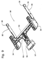
- the actuation button 52 is a forwardly extending portion of a slide link 53 of the slide apparatus that is mounted for longitudinal sliding movement underneath the lower tray 32, as can be seen best in Figs. 6 - 9 .
- the slide link 53 is T-shaped, and has laterally extending arms that terminate in engagement cups 54.
- Each engagement cup 54 captures the engagement member 59 of the respective actuation arm 57 therein. Accordingly, the action of depressing the actuation button 52 causes the slide link 53 to move rearwardly underneath the lower tray 32, and, thus, affects a rearward movement of the engagement cups 54.
- each arm rest 23 adjacent the respective socket 28 is sloped upwardly and rearwardly to define a cam surface that contacts the rectangular lock pin 55a of the respective latch member 55 when the respective tray post 35 is first inserted into the socket 28 of the respective arm rest 23.
- the engagement contact between the cam surface and the lock pin 55a forces the respective latch member 55 to pivot upwardly into the respective tray post 35 against the biasing force of the spring 56 so that the lock pin 55a does not restrict the movement of the respective tray post 35 into the socket 28.
- each lock pin 55a retracts into the respective tray post 35, slides over the second roller 29 until the lock pin 55a becomes aligned with a first one of the openings in the socket 28 of the respective arm rest 23, whereupon the spring 56 pivots the latch member 55 downwardly to engage the lock pin 55a with this opening and stops the rearward movement of the respective tray post 35 within the socket 28.
- a forward side of the lock pin 55a is squared off so that forward longitudinal forces exerted onto the tray system 30 do not cause a cam action that pops the lock pin 55a out of engagement with the selected opening in the socket 28 of the respective arm rest 23.
- a rearward side of the lock pin 55a is formed with an acute back angle that resists rearward longitudinal forces which have a tendency to pop the lock pin 55a out of the socket 28.
Abstract
Description
- The present invention relates to a child's high chair having a tray system with a latch mechanism that permits easy installation of the tray system while providing positional adjustment.
- Different products are used by parents to aid in the positioning of their child to facilitate feeding them from the time the child is an infant until the child is old enough and large enough to sit at a table properly. One such product is a high chair, which is typically used to support infants and small toddlers at an elevated position so that the caregiver can easily feed the child. The high chair is a self-standing unit that provides a safe and secure seating area with a feeding tray that is removable from the high chair to facilitate the placement of the child on the high chair and to facilitate the cleaning of the tray and high chair structure. High chairs can incorporate height adjustment mechanism so that the seat can be vertically positioned to fit various table heights so that the tray mechanism could be removed from the high chair and the child positioned on the high chair be pushed up to a table.
- High chairs can provide different tray options. Some high chair configurations provide a smaller snack tray under the typical large high chair tray. These snack trays are attached to the high chair seat and do not have the ability to be adjusted in and out to accommodate different child sizes. Furthermore, since the snack tray is directly attached to the high chair seat, the caregiver is required to lift the child up and over the snack tray in order to seat the child in the high chair, or to remove the child from the high chair. Although some snack trays can be removed from the high chair seat without tools, the removal of the snack tray typically requires two hands and the snack tray is usually only removed when the high chair is being used without the large tray, such as when the child in the high chair is pushed directly up to the table. While the snack tray is not typically adjustable positionally, the large tray is usually positionally adjustable on the snack tray.
- Only a few high chairs commercially available utilize a post to socket tray connection, in which the tray is formed with rearwardly projecting horizontal posts that are received within sockets formed in the high chair structure. The post and socket design can be advantageous over other tray mounting designs in that the tray is easy to align when fastening to the high chair seat and the tray offers a strong interlocking connection with the high chair structure to withstand extreme cases of abuse during product use. Even so, the post and socket design is not without drawbacks. The post and socket tray mounting design typically suffers fromhigh amounts of friction between post and socket and from the need to actuate the tray adjustment mechanism before for connecting the tray to the high chair seat.
- The friction problem is typically resolved in a limited manner by using dissimilar materials for the tray post and high chair socket components. While dissimilar materials do aid in reducing the friction problem, the post and socket mounting trays often remain difficult to adjust positionally relative to the high chair as the tray posts often bind or stick. The caregiver can become frustrated and loose motivation for removing the tray altogether. As a result, the value of having a removable tray can be unrealized or under appreciated by the caregiver.
- Furthermore, inserting the tray posts into the high chair receiving sockets canbe cumbersome, as often times, the user tries to attach the tray to the high chair structure only to find that the locking mechanism, which is located in the tray post is obstructing insertion of the post into the socket. As a result, the locking mechanism must first be actuated before the tray can be attached to the high chair. Actuating the lock mechanism while trying to attach the tray using only one hand is a more difficult task than any caregiver should have to undertake. A tray latching mechanism is disclosed in
U. S. Patent No. 4,807,928, issued on February 28, 1989 to Richard Cone , wherein the tray latching mechanism enables the tray to adjust the position of the tray relative to the high chair and to be located back at the same selected position each time the tray is removed from the high chair. The tray latching mechani sm is actuated by pulling a central front actuation handle to adjust the tray position related to the high chair and by pushing the handle to remove the tray from or mount the tray onto the high chair armrests. -
U. S. Patent No. 5,238,292, granted on August 24, 1993, to Douglas Golenz, et al , also teaches a front, centrally positioned actuator lever that operates a latch mechanism for a removable high chair tray through several linkages that affect rotation of a central member to operate laterally positioned engagement members such that the pulling of the central lever releases the engagement of the tray with the high chair arm rests. Similarly, the front, central actuation member in the high chair tray inU. S. Patent No. 5, 348, 374, granted to Tzu-Yu Kuo on September 20, 1994 , slides a cam actuator into laterally extending actuator arms to operate engagement members on the lateral sides of the tray apparatus. - Another centrally mounted actuator lever that moves a linkage to cause a latching and unlatching operation for the tray is shown in
U. S. Patent No. 5,489,138, issued to John Mariol, et al on February 6, 1996 . The actuated linkage engages recesses formed in the sides of the arm rests of the high chair to provide a fore-and-aft adjustment feature for the tray.U. S. Patent No. 6,416,124 discloses a highchair having a central actuator operable to move horizontal and vertical components underneath the tray, and a pair-of supports on opposite sides of the high chair, each having a plurality of elastic projections on the inside and a movable tray coupled between the supports. The supports further comprise a tube disposed on a leg of the high chair and a plurality of studs releasably coupled to the highchair. -
WO96/13999 -
US2440224 discloses a high chair tray slide. - None of the cited prior art shows a latch mechanism, or a position adjustment mechanism, that would allow a one-handed insertion of a tray onto the structure of a high chair, without requiring the manipulation of the latch mechanism to affect the mounting of horizontally extending tray posts into corresponding sockets. It would be desirable to provide a latch mechanism for a high chair tray structure that will allow an easy positioning of the tray on the high chair and provide improved flexibility in the use of the tray.
- The present invention provides a high chair, as defined in claim 1. Optional features are recited in the dependent claims.
- Optionally, the tray post incorporates a latch member that projects below the tray post for engagement with openings in a bottom surface of the socket to positionally secure the tray system in a selected position on the high chair structure.
- It is an advantage of this invention that the retractable latch member allows installation of the tray system onto the high chair structure without requiring manipulation of the latch mechanism.
- Optionally, the latch member pivots into engagement with a first opening in the bottom surface of the socket to latch the tray system into position after being passively inserted into the arm rest.
- Optionally, positional adjustment of the tray system requires manipulation of the latch mechanism only after the tray system has been mounted onto the high chair structure.
- Optionally, the tray system requires manipulation of the latch mechanism to dismount the tray system from the high chair structure.
- Optionally, the latch mechanism includes an actuation button centrally positioned at the front of the tray system.
- Optionally, the actuation button is conveniently accessible by a caregiver for operation using a single hand.
- Optionally, the actuation button moves a slide member positioned underneath the tray system to branch laterally for operation of a linkage housed within each of the tray posts.
- Optionally, each of the actuation linkages in the tray posts includes a slidable actuation arm engaged with a central slide member underneath the tray system.
- Optionally, the centrally positioned actuation button is operable to move simultaneously the actuation arms in the opposing tray posts.
- Optionally, each of the slidable actuation arms includes a cam surface to cause pivotal movement of the latch member when moved into engagement with the latch member so as to affect a release of the latch member from the selected one of the openings in the socket of the arm rest.
- In one embodiment of the present invention, the latch mechanism of the high chair includes a central, front actuation button that moves a slide link mounted underneath the tray system. The slide link is connected to an actuation arm slidably mounted within each respective tray post. The actuation arm includes a cam surface that pivots a latch member having a rectangular lock pin that extends below the tray post into engagement with a selected one of openings in the socket receiving the tray post. The latch member is spring-loaded into engagement with the selected opening in the socket. A front surface of a respective arm rest of a high chair structure is sloped to cam the lock pin into the tray post so as to permit a passive mounting of the tray system onto the high chair structure, but it requires a non-passive manipulation to affect positional adjustment or removal once the lock pin is engaged with one of the openings.
- The advantages of this invention will be apparent upon consideration of the following detailed disclosure of the invention, especially when taken in conjunction with the accompanying drawings wherein:
-
Fig. 1 is a front perspective view of a high chair incorporating the principles of the instant invention; -
Fig. 2 is a cross-sectional view through a tray post of a tray system and a socket of a high chair structure to depict mounting of the tray system to the high chair structure; -
Fig. 3 is a cross-sectional view of the tray system removed from the high chair structure; -
Fig. 4 is a side elevational view of a lower tray of the tray system provided with the tray post, where portions of the lower tray are broken away to permit viewing of component parts within the tray post; -
Fig. 5 is an exploded upper perspective view of the tray system including the lower tray, an upper tray and a tray insert; -
Fig. 6 is an exploded lower perspective view of the tray system shown inFig. 5 ; -
Fig. 7 is an assembled lower perspective view of the tray system; -
Fig. 8 is a bottom plan view of the lower tray with the upper tray removed therefrom; -
Fig. 9 is an upper perspective view of a position adjustment actuation mechanism, movement of a slide link being shown in phantom; and -
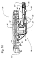
Fig. 10 is a side elevational view of the tray system with portions thereof broken away to permit better view of the position adjustment actuation mechanism. - Referring now to the drawings, a high chair incorporating the principles of the instant invention can best be seen. In terms of general structure, the high chair includes a
high chair structure 10 and a multiple tray system 30 (hereinafter also referred to as the "tray system 30"). Thehigh chair structure 10 includes a Z-shapedframe 11 that has abase portion 12 and a generally vertically extendingupright portion 13 which meets thebase portion 12 at an acute angle, and aseat member 20. Theupright portion 13 includes a pair of laterally spacedbase legs 17 for receiving respectivetelescopic legs 14 that can be optionally spring-biased to an extended position so as to offset the weight of theseat member 20 and a child that can be seated in theseat member 20. Position of thetelescopic legs 14 relative to thebase legs 17 is controlled by a heightadjustment latch mechanism 15 having an actuator 16 that is supported on each of thetelescopic legs 14. Thebase portion 12 is preferably equipped with a set of fixedwheels 19 at joints between thebase portion 12 and thebase legs 17 of theupright portion 13, and a pair ofcaster wheels 18 to provide mobility to the Z-shapedframe 11. - The Z-shaped
frame 11 supports theseat member 20 at an upper portion thereof. Theseat member 20 is formed with a generallyhorizontal seat portion 22, which is surrounded on two lateral sides thereof byupright side walls 23 that form arm rests 23, and in the back between the arm rests 23 by a seat back 25. The front of theseat member 20 is open to accommodate the legs of a child seated on theseat portion 22, and is formed with afoot rest support 24 that extends downwardly from a forward edge of theseat portion 22. Thefoot rest support 24 is preferably formed with a plurality of vertically spaced pairs of horizontally oriented mountingslots 26 into which afoot rest 27 can be inserted for selective positioning according to the size of the child being supported on theseat member 20. Theseat member 20 is supported on the Z-shapedframe 11, but is positioned such that theside wall 23, particularly along the back portion of theseat member 20, is spaced from the Z-shapedframe 11, which preferably curves from onetelescopic leg 14 to the other. - The
tray system 30 is generally formed of first andsecond tray members lower tray 32 that is mounted removably to thehigh chair structure 10, as will be described in greater detail below, and a largerupper tray 40, and anoptional tray insert 47, which can be seen best in the exploded views ofFigs. 5 and6 . Thelower tray 32, which can also be referred to as a travel tray since this smaller tray takes up less space when traveling than the largerupper tray 40, is sized to fit within adepression 41 formed into an underside of theupper tray 40. The underside of theupper tray 40 is provided with a pair of laterally spacedlatch members 43 that are positioned to engage sides of thelower tray 32 so as to allow theupper tray 40 to be mounted on top of thelower tray 32. Thelatch members 43 are preferably slidable along the underside of theupper tray 40 so as to be movable between an outward release position and an inward engagement position. - The
latch members 43 project below the underside of theupper tray 40 so as to be engageable with the sides of thelower tray 32, and so that a top surface of thelower tray 32 will nest the largerupper tray 40. With the nesting arrangement between the upper andlower trays upper tray 40 is only positioned a short distance above thelower tray 32 substantially equal to the thickness of the material forming theupper tray 40. Since theupper tray 40 does not incorporate a position adjustment mechanism that enables theupper tray 40 to be movable relative to thelower tray 32, the overall vertical height of thetray system 30 is minimized and is easier to manipulate with one hand. - Preferably, the
latch members 43 are spring-biased into the inward engagement position such that the caregiver would need to grasp thelatch members 43 on both sides and pull thelatch members 43 outwardly so as to affect a release of the sides of thelower tray 32 and to enable removal of theupper tray 40 from thelower tray 32. Conversely, the shape of each of thelatch members 43 should be beveled along aninterior side 44 thereof so that theupper tray 40 can be installed onto thelower tray 32 simply by positioning theupper tray 40 over thelower tray 32 and pressing downwardly thereon. The beveledinterior sides 44 of thelatch members 43 will cam thelatch members 43 outwardly to allow the engagement thereof with the sides of thelower tray 32, with the spring bias closing thelatch members 43 into the engagement position. - An
upper surface 45 of theupper tray 40 is depressed so as to provide arimmed surface 45 that retains food and other items. Thetray insert 47 can be placed onto theupper surface 45 of theupper tray 40, as is reflected in the exploded views ofFigs. 5 and6 , to provide a readily removable surface that can facilitate cleaning of theupper tray 40. Thetray insert 47 can be formed with a downwardly extendingrear ledge 48 that incorporates asmall retainer lip 49 at a center thereof. Thetray insert 47 is sized to fit into the depressedupper surface 45 of theupper tray 40 with therearward ledge 48 extending downwardly along a side surface of theupper tray 40 so that theretainer lip 49 can snap under theupper tray 40 and detachably secure thetray insert 47 on theupper tray 40. As shown inFigs. 5 and6 , thetray insert 47 can be shaped to be compartmentalized, including a circular compartment for a cup, for example. - The
lower tray 32 is formed with a pair of laterally spaced, rearwardly extending, generally horizontal tray posts 35, each of which is shaped to fit into asocket 28 formed in an upper portion of arespective arm rest 23. Each of the tray posts 35 have a post body and afirst anti-friction member 36, which, in this embodiment, is in a form of afirst roller 36 mounted at a distal end of the post body and located along an upper surface of the post body so that thefirst roller 36 can engage a top surface of thesocket 28 as thetray post 35 moves within thesocket 28. Furthermore, thesocket 28 of each of the arm rests 23 includes a socket body and asecond anti-friction member 29, which, in this embodiment, is in the form of asecond roller 29 built into the structure of thearm rest 23 on a lower surface of the socket body near the front end of the socket body, as can be seen best inFig. 2 . Thesecond roller 29 supports an underside of the post body of the respective tray post 35 as the respective tray post 35 moves within the socket body of thesocket 28. With the combination of thefirst roller 36 on the distal end of the post body of thetray post 35 and thesecond roller 29 near the front of the socket body of thesocket 28, thetray post 35 can move within thesocket 28 effortlessly without concern over frictional forces. - From a structural standpoint, the
lower tray 32 is formed as a relativelyflat tray member 33 withlateral legs 34 on opposing sides of thetray member 33 to elevate thetray member 33 above the tray posts 35 that extend rearwardly from thelateral legs 34. A central part of thelower tray 32 is formed with aretention horn member 39 that projects downwardly from thetray member 33 to restrict movement of a child placed on theseat member 20 when thetray system 30 is mounted to thehigh chair structure 10. Theretention horn member 39 is positionally adjustable with thelower tray 32 relative to theseat portion 22 of theseat member 20. Furthermore, when thelower tray 32 is removed from thehigh chair structure 10, all obstructions to placing a child onto theseat portion 22, such as the first andsecond tray members retention horn member 39, are removed from thehigh chair structure 10 to facilitate positioning of the child onto theseat portion 22. - The first and
second rollers second rollers sockets 28. However, the first andsecond rollers socket 28 and the bottom of the post body of thetray post 35 to provide contact points between thetray post 35 and thesocket 28 with minimal friction therebetween so as to facilitate positioning and adjustment of thetray system 30. - In addition, one skilled in the art will recognize that the
first roller 36 is placed at the top of the distal end of the post body of therespective tray post 35, and thesecond roller 29 is located at the lower surface at the front of the socket body of thesocket 28 of the respective arm rest 23 because the weight of the tray members (i.e., thelower tray 32, the upper tray 40) and thetray insert 47 is exerted through thelateral legs 34 to forward ends of the post bodies of the tray posts 35, which form a cantilevered arrangement when the tray posts 35 are mounted in thesockets 28. Thus, the tray posts 35 are normally inclined within thesockets 28 so that the distal end of the post body of each of the tray posts 35 is pressed into the top surface of the socket 2B of therespective arm rest 23, and the tray posts 35 bear on the lower, front surface of thesockets 28. However, with this arrangement, an upward force exerted on a front of thetray assembly 30 can cause some movements of the tray posts 35 within thesockets 28. Accordingly, an optional third roller (not shown) could be placed into a lower surface of the socket body of thesocket 28 of eacharm rest 23 at a selected location spaced rearwardly of thesecond roller 29 to provide additional support for the respective tray post 35 when therespective tray post 35 is received within thesocket 28. - Operationally, the mounting of the larger
upper tray 40 on the smallerlower tray 32, when thelower tray 32 is adjustably mounted on thehigh chair 10, allows theentire tray system 30 to be positionally adjusted relative to theseat portion 22 to accommodate differently sized children. A position adjustment actuation mechanism 50 (hereinafter also referred to as the "latch mechanism 50"), which will be described in greater detail below, allows thetray system 30 to be mounted onto thehigh chair structure 10 by simply aligning the tray posts 35 with thesockets 28 and inserting the tray posts 35 into thesockets 28 with a rearwardly directed force without manipulation of the positionadjustment actuation mechanism 50. Accordingly, thetray system 30 can be placed onto thehigh chair structure 10 by the caregiver with a single hand, which is a significant advantage especially to a caregiver holding a child. Furthermore, not only is the position of the largerupper tray 40 adjustable, the position of thelower tray 32 can also be adjusted relative to thehigh chair structure 10. - The position
adjustment actuation mechanism 50 is housed in thelower tray 32, and includes anactuation member 52, which is in the form of anactuation button 52 in this embodiment, and which is located at the front of thelower tray 32 for convenient access thereto. Preferably, theactuation button 52 projects outwardly from thelower tray 32 for a distance sufficient to accommodate the positioning of the largerupper tray 40 on top of thelower tray 32 such that when theupper tray 40 is positioned on top of thelower tray 32, a face of theactuation button 52 is substantially aligned with a forward edge of theupper tray 40. To permit this positioning of theupper tray 40, theupper tray 40 is formed with a correspondingnotch 42 in the forward edge thereof to receive theactuation button 52. - The lower surface of the
socket 28 of each of the arm rests 23 is formed with a series of longitudinally spaced openings therein to receive alock pin 55a forming a tip of arespective latch member 55 of thelatch mechanism 50. Thelatch member 55 is pivotally mounted within a respective tray post 35 at the distal end thereof with thelock pin 55a projecting out of the respective tray post 35 into engagement with a selected one of the openings in thesocket 28 so as to be engaged therewith when thelower tray 32 is mounted to theseat member 20 of thehigh chair structure 10, where each opening corresponds to an adjusted position of thetray system 30 relative to theseat member 20. Preferably, the pivotedlatch member 55 is biased to engage thelock pin 55a with the openings in thesocket 28 by aspring 56 so that thelower tray 32 is retained in the selected position until a positive action is undertaken to release thelatch member 55 from engagement with the selected opening in thesocket 28. - The positive action to force the release of the
lock pin 55a from engagement with the selected opening in the lower surface of thesocket 28 is provided by arespective actuation arm 57 of a slide apparatus that is mounted slidably within the respective tray post 35 for sliding movement in a fore-and-aft direction. Theactuation arm 57 is formed with acam surface 58 that is positioned to engage thelatch member 55 and to force upward pivotal movement thereof against the biasing force exerted by thespring 56 when theactuation arm 57 is operated to slide rearwardly to retract therectangular lock pin 55a into therespective tray post 35. A forward portion of theactuation arm 57 is formed with an upwardly extendingengagement member 59. - The
actuation button 52 is a forwardly extending portion of aslide link 53 of the slide apparatus that is mounted for longitudinal sliding movement underneath thelower tray 32, as can be seen best inFigs. 6 - 9 . Theslide link 53 is T-shaped, and has laterally extending arms that terminate inengagement cups 54. Eachengagement cup 54 captures theengagement member 59 of therespective actuation arm 57 therein. Accordingly, the action of depressing theactuation button 52 causes theslide link 53 to move rearwardly underneath thelower tray 32, and, thus, affects a rearward movement of the engagement cups 54. Since theengagement members 59, which are formed on therespective actuation arms 57, are received within the engagement cups 54, rearward movement of the engagement cups 54 brings theactuation arms 57 to also slide rearwardly within the respective tray posts 35 so as to force the cammed ends 58 of theactuation arms 57 into engagement with therespective latch members 55 so as to cause an upward pivotal movement of thelatch members 55 against the biasing forces of thesprings 56 such that the lock pins 55a of thelatch members 55 are disengaged from the selected openings in thesockets 28 of the respective arm rests 23. Theslide link 53 is spring-loaded forwardly by a spring 51 to bias thelatch mechanism 50 into a locked position in which the lock pins 55a are extended out of the respective tray posts 35. Accordingly, theactuation button 52 will only remain depressed as long as sufficient force is applied to overcome the forces exerted by the spring 51. - As can be seen best in
Fig. 2 , an exterior surface of eacharm rest 23 adjacent therespective socket 28 is sloped upwardly and rearwardly to define a cam surface that contacts therectangular lock pin 55a of therespective latch member 55 when therespective tray post 35 is first inserted into thesocket 28 of therespective arm rest 23. The engagement contact between the cam surface and thelock pin 55a forces therespective latch member 55 to pivot upwardly into the respective tray post 35 against the biasing force of thespring 56 so that thelock pin 55a does not restrict the movement of the respective tray post 35 into thesocket 28. Accordingly, eachlock pin 55a retracts into therespective tray post 35, slides over thesecond roller 29 until thelock pin 55a becomes aligned with a first one of the openings in thesocket 28 of therespective arm rest 23, whereupon thespring 56 pivots thelatch member 55 downwardly to engage thelock pin 55a with this opening and stops the rearward movement of the respective tray post 35 within thesocket 28. - Further rearward movement of the
tray system 30 can then be accomplished by depressing theactuation button 52 to cause thelatch members 55 to be lifted and, as a result, the lock pins 55a to be retracted, until the desired positioning of thetray system 30 is achieved. Preferably, a forward side of thelock pin 55a is squared off so that forward longitudinal forces exerted onto thetray system 30 do not cause a cam action that pops thelock pin 55a out of engagement with the selected opening in thesocket 28 of therespective arm rest 23. A rearward side of thelock pin 55a is formed with an acute back angle that resists rearward longitudinal forces which have a tendency to pop thelock pin 55a out of thesocket 28. Thus, once thelock pin 55a is aligned with the first opening in thesocket 28 of the respective arm rest 23 as therespective tray post 35 is first inserted into thesocket 28, operation of the positionadjustment actuation mechanism 50 is necessary to either adjust the fore-and-aft position of thetray system 30 or affect a removal of thetray system 30 from thehigh chair structure 10.
Claims (4)
- A high chair, comprising:a high chair structure (10); anda tray system (30) with a latch mechanism (50), the tray system (30) formed with tray posts (35) that are used for mounting on the high chair structure (10), the high chair structure (10) having laterally spaced arm rests (23), each of which is formed with a socket (28) to receive a corresponding one of the tray posts (35);said latch mechanism (50) comprising:a latch member (55) movably mounted within each said tray post (35) and having a lock pin (55a) projecting out of said tray post (35), said latch member (55) being engageable with a corresponding one of the arm rests (23) to affect retraction of said lock pin (55a) into the corresponding one of the tray posts (35) when the corresponding one of the tray posts (35) is initially inserted into the socket (28) of the corresponding one of the arm rests (23);wherein said lock pin (55a) is formed in a generally rectangular shape to resist push/pull forces when engaged in an opening in the socket (28) of the corresponding one of the arm rests (23), each of the armrests (23) including a sloped surface located to affect retraction of said lock pin (55a) into the corresponding one of the tray posts (35) when the corresponding one of the tray posts (35) is initially inserted into the socket (28) of the corresponding one of the arm rests (23); andwherein each of said latch members (55) is pivotally mounted within the corresponding one of the tray posts (35), and is spring-biased to project said lock pin (55a) out of the corresponding one of the tray posts (35) for engagement with the opening in the socket (28) of the corresponding one of the arm rests (23);characterised in that the socket (28) is formed with a plurality of openings, the openings in the socket (28) being provided for selective engagement of said lock pin (55a) to secure the tray system (30) at a selected position on the high chair structure (10); andin that the latch mechanism (50) comprises an actuation arm (57) slidably mounted within a corresponding one of the tray posts (35) for engagement with a corresponding one of said latch members (55) to affect a pivotal movement thereof so as to retract said lock pin (55a) into the corresponding one of the tray posts (35).
- The high chair of Claim 1, wherein each of said actuation arms (57) includes a cam surface (58) engageable with the corresponding one of said latch members (55) to affect said pivotal movement thereof when said actuation arm (57) is moved into engagement with the corresponding one of said latch members (55).
- The high chair of Claim 2, further comprising a slide link (53) mounted to the tray system (30), and connected to said actuation arms (57), said slide link (53) including an actuation button (52) positioned on the tray system (30) to cause a sliding movement of said slide link (53) and said actuation arms (57) when manipulated.
- The high chair of Claim 2, wherein each of said actuation arms (57) is formed with an upright engagement member (59) coupled with an engagement cup (54) that is formed on said slide link (53) to transfer the sliding movement of said slide link (53) to said actuation arms (57).
Applications Claiming Priority (1)
| Application Number | Priority Date | Filing Date | Title |
|---|---|---|---|
| US6630908P | 2008-02-19 | 2008-02-19 |
Publications (3)
| Publication Number | Publication Date |
|---|---|
| EP2092857A2 EP2092857A2 (en) | 2009-08-26 |
| EP2092857A3 EP2092857A3 (en) | 2012-03-28 |
| EP2092857B1 true EP2092857B1 (en) | 2013-11-20 |
Family
ID=40821747
Family Applications (3)
| Application Number | Title | Priority Date | Filing Date |
|---|---|---|---|
| EP13154829.9A Withdrawn EP2606773A1 (en) | 2008-02-19 | 2009-02-18 | Tray system for child's high chair |
| EP09153127.7A Active EP2092858B1 (en) | 2008-02-19 | 2009-02-18 | Tray system for child's high chair |
| EP09153125.1A Active EP2092857B1 (en) | 2008-02-19 | 2009-02-18 | High chair with a tray latch mechanism |
Family Applications Before (2)
| Application Number | Title | Priority Date | Filing Date |
|---|---|---|---|
| EP13154829.9A Withdrawn EP2606773A1 (en) | 2008-02-19 | 2009-02-18 | Tray system for child's high chair |
| EP09153127.7A Active EP2092858B1 (en) | 2008-02-19 | 2009-02-18 | Tray system for child's high chair |
Country Status (4)
| Country | Link |
|---|---|
| US (2) | US8201879B2 (en) |
| EP (3) | EP2606773A1 (en) |
| JP (3) | JP5129177B2 (en) |
| CN (3) | CN101513310A (en) |
Families Citing this family (42)
| Publication number | Priority date | Publication date | Assignee | Title |
|---|---|---|---|---|
| US8201879B2 (en) * | 2008-02-19 | 2012-06-19 | Wonderland Nurserygoods Co., Ltd | Tray system for child's high chair |
| JP2012096000A (en) * | 2010-11-04 | 2012-05-24 | Bp Children's Products Hk Co Ltd | Child high chair having detachable footrest |
| TWI417071B (en) * | 2010-11-04 | 2013-12-01 | Bp Childrens Prod Hk Co Ltd | Child high chair having a detachable pedal |
| CN102599764A (en) * | 2011-01-21 | 2012-07-25 | 明门香港股份有限公司 | Combined type dinner plate |
| US20160270542A1 (en) * | 2011-07-22 | 2016-09-22 | Robert Foster | Spectator Tray |
| US9039079B2 (en) * | 2012-04-12 | 2015-05-26 | Mattel, Inc. | Children's tray with placement indicator |
| CN202919645U (en) * | 2012-05-02 | 2013-05-08 | 中山市隆成日用制品有限公司 | Infant chair back adjusting mechanism |
| US8696055B2 (en) * | 2012-09-14 | 2014-04-15 | Helen Of Troy Limited | Highchair with adjustable tray and seat height |
| KR101412975B1 (en) * | 2012-10-05 | 2014-06-27 | 김진성 | Multi tray for kids play of hard case shape |
| CN103126422B (en) * | 2013-03-08 | 2015-02-18 | 昆山小小恐龙儿童用品有限公司 | Spilt children dinning plate |
| CN104337282B (en) * | 2013-07-31 | 2017-08-08 | 明门香港股份有限公司 | Children's seat and its armrest adjusting device |
| USD742657S1 (en) | 2013-09-18 | 2015-11-10 | Graco Children's Products, Inc. | High chair |
| US9565929B2 (en) | 2013-10-17 | 2017-02-14 | Regalo International, Llc | Dine and draw child lap tray apparatus |
| US9895005B2 (en) | 2014-05-21 | 2018-02-20 | Kids Ii, Inc. | Convertible child seat |
| WO2016018627A1 (en) * | 2014-08-01 | 2016-02-04 | Thorley Industries Llc | Infant chairs |
| US10588424B2 (en) | 2015-04-25 | 2020-03-17 | Kids2, Inc. | Convertible high chair |
| CN205866475U (en) * | 2015-04-25 | 2017-01-11 | 儿童二代公司 | Children strutting arrangement and be used for feeding tray rather than children that are used together |
| US11723477B2 (en) | 2015-04-25 | 2023-08-15 | Kids2, Inc. | Convertible highchair |
| US11877671B2 (en) | 2015-04-25 | 2024-01-23 | Kids2, Inc. | Convertible high chair |
| USD781059S1 (en) | 2015-11-24 | 2017-03-14 | Mattel, Inc. | Infant support structure |
| USD802853S1 (en) * | 2016-04-04 | 2017-11-14 | Macneil Ip Llc | Pet feeding system |
| USD887650S1 (en) | 2016-04-04 | 2020-06-16 | Macneil Ip Llc | Pet water station |
| USD873504S1 (en) | 2016-04-04 | 2020-01-21 | Macneil Ip Llc | Compact mat for pet feeding system |
| USD873503S1 (en) | 2016-04-04 | 2020-01-21 | Macneil Ip Llc | Pet feeding system |
| USD894498S1 (en) | 2016-04-04 | 2020-08-25 | Macneil Ip Llc | Single-bowl pet water/food station |
| USD873502S1 (en) | 2016-04-04 | 2020-01-21 | Macneil Ip Llc | Double bowl low-profile pet feeding station |
| DE102018204778B4 (en) | 2017-04-04 | 2019-06-27 | Wonderland Switzerland Ag | Multifunctional highchair |
| US10561254B2 (en) | 2017-04-04 | 2020-02-18 | Wonderland Switzerland Ag | Child tray assembly and multi-function high chair |
| CN107928246A (en) * | 2017-11-28 | 2018-04-20 | 好孩子儿童用品有限公司 | Children dinning chair |
| US10709259B2 (en) * | 2018-03-05 | 2020-07-14 | Wonderland Switzerland Ag | Latch mechanism and tray assembly |
| US10588425B1 (en) * | 2018-06-08 | 2020-03-17 | Angelica Jordan | Child seat system |
| CN108784128A (en) * | 2018-06-21 | 2018-11-13 | 东莞市鸿福物业管理服务有限公司 | Multipurpose highchair |
| US20200156279A1 (en) * | 2018-11-16 | 2020-05-21 | Corvesco Co. Ltd. | Cutting tool latch assembly |
| US11166570B1 (en) | 2019-03-19 | 2021-11-09 | Regalo International, Llc | High chair apparatus with wide foot print |
| US11641952B2 (en) | 2019-06-21 | 2023-05-09 | Kids2, Inc. | Modular cradle |
| USD880787S1 (en) * | 2019-08-19 | 2020-04-07 | David H. Price | Mat |
| USD880788S1 (en) * | 2019-08-19 | 2020-04-07 | David H. Price | Mat |
| US11589682B2 (en) | 2019-09-19 | 2023-02-28 | Thorley Industries, Llc | Infant chairs |
| USD958897S1 (en) | 2020-09-17 | 2022-07-26 | Kids2, Inc. | Modular toy bar |
| USD979259S1 (en) | 2020-09-17 | 2023-02-28 | Kids2, Inc. | Modular swing |
| USD977865S1 (en) | 2020-09-17 | 2023-02-14 | Kids2, Inc. | Modular cradle |
| CN112704355A (en) * | 2020-12-29 | 2021-04-27 | 鲍逸怡 | Assembly structure of dinner plate assembly and child dining chair |
Family Cites Families (39)
| Publication number | Priority date | Publication date | Assignee | Title |
|---|---|---|---|---|
| US1505518A (en) * | 1922-07-12 | 1924-08-19 | Jr Samuel T Workman | High chair |
| US1859150A (en) | 1931-03-31 | 1932-05-17 | Joseph V Moran | Baby chair |
| US2115860A (en) * | 1937-05-21 | 1938-05-03 | Kroll Samuel | Latch for high chair tables |
| US2440224A (en) * | 1945-03-26 | 1948-04-20 | Nat Lock Co | High chair tray slide |
| US2767774A (en) | 1952-03-13 | 1956-10-23 | George T Derby | High chair with tray attachment |
| US3239255A (en) * | 1964-04-06 | 1966-03-08 | Charles E Murcott | One directional movement catch device |
| US3580631A (en) * | 1969-02-10 | 1971-05-25 | Lumex | Invalid chair |
| US3635522A (en) * | 1969-09-29 | 1972-01-18 | Kerwit Medical Products Inc | Surgical treatment method and apparatus |
| JPH0336311Y2 (en) * | 1985-08-14 | 1991-08-01 | ||
| US4632451A (en) * | 1986-02-10 | 1986-12-30 | Lee Henry D | Wheelchair table and desk attachments |
| JPH0339090Y2 (en) * | 1986-10-22 | 1991-08-16 | ||
| US4807928A (en) * | 1987-09-18 | 1989-02-28 | Gerico, Inc. | Tray apparatus for use with a chair |
| JPH0339091Y2 (en) * | 1988-12-27 | 1991-08-16 | ||
| IT1228724B (en) * | 1989-03-15 | 1991-07-03 | Cam Di Rho Gianfranco Aldo E M | Baby's high chair |
| US5238292A (en) * | 1991-09-04 | 1993-08-24 | Gerry Baby Products Company | Highchair with adjustable seat |
| DE9212161U1 (en) | 1992-08-06 | 1993-01-21 | Kuo, Tzu-Yu, Tainan, Tw | |
| US5489138A (en) * | 1993-10-01 | 1996-02-06 | Lisco, Inc. | Height adjustable high chair |
| US5468043A (en) * | 1994-08-16 | 1995-11-21 | Jina Manufacturer Thai Co., Ltd. | Foldable chair |
| US5527090A (en) * | 1994-11-04 | 1996-06-18 | Cosco, Inc. | Child seat tray assembly |
| US5810432A (en) * | 1995-11-09 | 1998-09-22 | Graco Children's Products Inc. | High chair system |
| US6293623B1 (en) * | 1997-09-26 | 2001-09-25 | Cosco Management, Inc. | Juvenile seat assembly |
| TW419983U (en) * | 2000-06-02 | 2001-01-21 | Link Treasure Ltd | Adjustable type structure of a dish for a meal seat |
| US6347833B1 (en) * | 2000-09-11 | 2002-02-19 | Trident Company Ltd. | High chair having a seat-tilting mechanism |
| US20020036416A1 (en) * | 2000-09-22 | 2002-03-28 | Andrew Mendenhall | Multi-piece accessory tray |
| US6419312B1 (en) * | 2000-10-27 | 2002-07-16 | Regalo International, Llc | Incrementally slidable high chair tray with quick release |
| DE20019014U1 (en) * | 2000-11-08 | 2001-02-15 | Cheng Kenny | Locking device for an extension table |
| IT250483Y1 (en) * | 2000-11-17 | 2003-09-10 | Artsana Spa | HIGH CHAIR WITH SHELF PROVIDED WITH REMOVABLE COVER ELEMENT |
| US6511124B2 (en) * | 2001-01-23 | 2003-01-28 | Mark Ellis Combs | Tray table for a child's car seat and associated methods |
| CN2484828Y (en) | 2001-06-22 | 2002-04-10 | 李绍汉 | Quick assembled drawer |
| US6920830B1 (en) * | 2001-09-18 | 2005-07-26 | Mattel, Inc. | Removable tray insert and tray set |
| JP4014385B2 (en) * | 2001-10-16 | 2007-11-28 | 北川木工販売株式会社 | Infant chair |
| US20050006930A1 (en) * | 2003-03-26 | 2005-01-13 | Graco Children's Products Inc. | High chair |
| JP2005027764A (en) * | 2003-07-09 | 2005-02-03 | Showa Prod:Kk | Foldable table, drawer type seat, and table with seat |
| CA2465939C (en) * | 2004-04-30 | 2010-08-24 | Mattel, Inc. | Infant support with selectively covered tray |
| TWM258666U (en) * | 2004-05-13 | 2005-03-11 | Huei-Min Jhou | A multi-functional dining chair for children |
| US7261370B1 (en) * | 2004-12-03 | 2007-08-28 | Whitesell Jr Robert C | High chair apparatus |
| CN2794336Y (en) * | 2005-01-31 | 2006-07-12 | 上海统资电器有限公司 | Height regulator structure of baby high leg chair |
| CN2907410Y (en) * | 2006-06-13 | 2007-06-06 | 明门实业股份有限公司 | Retractable long-leg chair with locking device |
| US8201879B2 (en) * | 2008-02-19 | 2012-06-19 | Wonderland Nurserygoods Co., Ltd | Tray system for child's high chair |
-
2009
- 2009-02-07 US US12/367,514 patent/US8201879B2/en active Active
- 2009-02-07 US US12/367,516 patent/US7922244B2/en active Active
- 2009-02-17 JP JP2009034067A patent/JP5129177B2/en active Active
- 2009-02-18 EP EP13154829.9A patent/EP2606773A1/en not_active Withdrawn
- 2009-02-18 CN CNA200910009333XA patent/CN101513310A/en active Pending
- 2009-02-18 EP EP09153127.7A patent/EP2092858B1/en active Active
- 2009-02-18 EP EP09153125.1A patent/EP2092857B1/en active Active
- 2009-02-18 CN CN2009100093344A patent/CN101558947B/en active Active
- 2009-02-18 JP JP2009035226A patent/JP5468791B2/en active Active
- 2009-02-18 CN CN2010102292379A patent/CN101912209B/en active Active
-
2012
- 2012-08-21 JP JP2012182110A patent/JP5524297B2/en active Active
Also Published As
| Publication number | Publication date |
|---|---|
| JP2009195696A (en) | 2009-09-03 |
| EP2092858A2 (en) | 2009-08-26 |
| EP2092858A3 (en) | 2012-03-28 |
| EP2606773A1 (en) | 2013-06-26 |
| JP5468791B2 (en) | 2014-04-09 |
| US8201879B2 (en) | 2012-06-19 |
| CN101912209B (en) | 2012-05-09 |
| JP5524297B2 (en) | 2014-06-18 |
| US7922244B2 (en) | 2011-04-12 |
| CN101558947B (en) | 2013-01-23 |
| JP5129177B2 (en) | 2013-01-23 |
| CN101912209A (en) | 2010-12-15 |
| CN101558947A (en) | 2009-10-21 |
| JP2009195698A (en) | 2009-09-03 |
| US20090206638A1 (en) | 2009-08-20 |
| US20090206639A1 (en) | 2009-08-20 |
| EP2092857A3 (en) | 2012-03-28 |
| CN101513310A (en) | 2009-08-26 |
| EP2092857A2 (en) | 2009-08-26 |
| EP2092858B1 (en) | 2018-05-30 |
| JP2012223624A (en) | 2012-11-15 |
Similar Documents
| Publication | Publication Date | Title |
|---|---|---|
| EP2092857B1 (en) | High chair with a tray latch mechanism | |
| US11426008B2 (en) | Convertible high chair | |
| US7871125B2 (en) | Infant support with independently repositionable legs | |
| US4842331A (en) | Highchair with adjustable removable tray for one-hand operation | |
| US5507550A (en) | Highchair | |
| EP2765887B1 (en) | Highchair with adjustable tray and seat height | |
| US9498064B2 (en) | Swivel feeding seat | |
| US7201445B1 (en) | Feeding seat | |
| CN112806774A (en) | Convertible high chair assembly with detachable tray | |
| US20050006930A1 (en) | High chair | |
| US20070145790A1 (en) | Juvenile high chair | |
| US20130009428A1 (en) | Infant carrier with handle | |
| US11172764B2 (en) | Feature high chair | |
| US20210085094A1 (en) | Infant chairs | |
| US20230000263A1 (en) | Convertible high chair | |
| CN113547966A (en) | Child release assembly, car safety seat basket and child stroller basket | |
| GB2536526A (en) | Stroller | |
| JPH08336448A (en) | Walker |
Legal Events
| Date | Code | Title | Description |
|---|---|---|---|
| PUAI | Public reference made under article 153(3) epc to a published international application that has entered the european phase |
Free format text: ORIGINAL CODE: 0009012 |
|
| AK | Designated contracting states |
Kind code of ref document: A2 Designated state(s): AT BE BG CH CY CZ DE DK EE ES FI FR GB GR HR HU IE IS IT LI LT LU LV MC MK MT NL NO PL PT RO SE SI SK TR |
|
| AX | Request for extension of the european patent |
Extension state: AL BA RS |
|
| PUAL | Search report despatched |
Free format text: ORIGINAL CODE: 0009013 |
|
| AK | Designated contracting states |
Kind code of ref document: A3 Designated state(s): AT BE BG CH CY CZ DE DK EE ES FI FR GB GR HR HU IE IS IT LI LT LU LV MC MK MT NL NO PL PT RO SE SI SK TR |
|
| AX | Request for extension of the european patent |
Extension state: AL BA RS |
|
| RIC1 | Information provided on ipc code assigned before grant |
Ipc: A47D 15/00 20060101ALI20120220BHEP Ipc: A47D 1/00 20060101AFI20120220BHEP |
|
| 17P | Request for examination filed |
Effective date: 20120928 |
|
| AKX | Designation fees paid |
Designated state(s): AT BE BG CH CY CZ DE DK EE ES FI FR GB GR HR HU IE IS IT LI LT LU LV MC MK MT NL NO PL PT RO SE SI SK TR |
|
| 17Q | First examination report despatched |
Effective date: 20121122 |
|
| GRAP | Despatch of communication of intention to grant a patent |
Free format text: ORIGINAL CODE: EPIDOSNIGR1 |
|
| INTG | Intention to grant announced |
Effective date: 20130624 |
|
| GRAS | Grant fee paid |
Free format text: ORIGINAL CODE: EPIDOSNIGR3 |
|
| GRAA | (expected) grant |
Free format text: ORIGINAL CODE: 0009210 |
|
| AK | Designated contracting states |
Kind code of ref document: B1 Designated state(s): AT BE BG CH CY CZ DE DK EE ES FI FR GB GR HR HU IE IS IT LI LT LU LV MC MK MT NL NO PL PT RO SE SI SK TR |
|
| REG | Reference to a national code |
Ref country code: GB Ref legal event code: FG4D |
|
| REG | Reference to a national code |
Ref country code: CH Ref legal event code: EP |
|
| REG | Reference to a national code |
Ref country code: AT Ref legal event code: REF Ref document number: 641068 Country of ref document: AT Kind code of ref document: T Effective date: 20131215 |
|
| REG | Reference to a national code |
Ref country code: IE Ref legal event code: FG4D |
|
| REG | Reference to a national code |
Ref country code: DE Ref legal event code: R096 Ref document number: 602009020169 Country of ref document: DE Effective date: 20140116 |
|
| REG | Reference to a national code |
Ref country code: NL Ref legal event code: VDEP Effective date: 20131120 |
|
| REG | Reference to a national code |
Ref country code: AT Ref legal event code: MK05 Ref document number: 641068 Country of ref document: AT Kind code of ref document: T Effective date: 20131120 |
|
| REG | Reference to a national code |
Ref country code: LT Ref legal event code: MG4D |
|
| PG25 | Lapsed in a contracting state [announced via postgrant information from national office to epo] |
Ref country code: HR Free format text: LAPSE BECAUSE OF FAILURE TO SUBMIT A TRANSLATION OF THE DESCRIPTION OR TO PAY THE FEE WITHIN THE PRESCRIBED TIME-LIMIT Effective date: 20131120 Ref country code: SE Free format text: LAPSE BECAUSE OF FAILURE TO SUBMIT A TRANSLATION OF THE DESCRIPTION OR TO PAY THE FEE WITHIN THE PRESCRIBED TIME-LIMIT Effective date: 20131120 Ref country code: IS Free format text: LAPSE BECAUSE OF FAILURE TO SUBMIT A TRANSLATION OF THE DESCRIPTION OR TO PAY THE FEE WITHIN THE PRESCRIBED TIME-LIMIT Effective date: 20140320 Ref country code: LT Free format text: LAPSE BECAUSE OF FAILURE TO SUBMIT A TRANSLATION OF THE DESCRIPTION OR TO PAY THE FEE WITHIN THE PRESCRIBED TIME-LIMIT Effective date: 20131120 Ref country code: NL Free format text: LAPSE BECAUSE OF FAILURE TO SUBMIT A TRANSLATION OF THE DESCRIPTION OR TO PAY THE FEE WITHIN THE PRESCRIBED TIME-LIMIT Effective date: 20131120 Ref country code: FI Free format text: LAPSE BECAUSE OF FAILURE TO SUBMIT A TRANSLATION OF THE DESCRIPTION OR TO PAY THE FEE WITHIN THE PRESCRIBED TIME-LIMIT Effective date: 20131120 Ref country code: NO Free format text: LAPSE BECAUSE OF FAILURE TO SUBMIT A TRANSLATION OF THE DESCRIPTION OR TO PAY THE FEE WITHIN THE PRESCRIBED TIME-LIMIT Effective date: 20140220 |
|
| PG25 | Lapsed in a contracting state [announced via postgrant information from national office to epo] |
Ref country code: ES Free format text: LAPSE BECAUSE OF FAILURE TO SUBMIT A TRANSLATION OF THE DESCRIPTION OR TO PAY THE FEE WITHIN THE PRESCRIBED TIME-LIMIT Effective date: 20131120 Ref country code: BE Free format text: LAPSE BECAUSE OF FAILURE TO SUBMIT A TRANSLATION OF THE DESCRIPTION OR TO PAY THE FEE WITHIN THE PRESCRIBED TIME-LIMIT Effective date: 20131120 Ref country code: LV Free format text: LAPSE BECAUSE OF FAILURE TO SUBMIT A TRANSLATION OF THE DESCRIPTION OR TO PAY THE FEE WITHIN THE PRESCRIBED TIME-LIMIT Effective date: 20131120 Ref country code: AT Free format text: LAPSE BECAUSE OF FAILURE TO SUBMIT A TRANSLATION OF THE DESCRIPTION OR TO PAY THE FEE WITHIN THE PRESCRIBED TIME-LIMIT Effective date: 20131120 |
|
| PG25 | Lapsed in a contracting state [announced via postgrant information from national office to epo] |
Ref country code: PT Free format text: LAPSE BECAUSE OF FAILURE TO SUBMIT A TRANSLATION OF THE DESCRIPTION OR TO PAY THE FEE WITHIN THE PRESCRIBED TIME-LIMIT Effective date: 20140320 |
|
| PG25 | Lapsed in a contracting state [announced via postgrant information from national office to epo] |
Ref country code: EE Free format text: LAPSE BECAUSE OF FAILURE TO SUBMIT A TRANSLATION OF THE DESCRIPTION OR TO PAY THE FEE WITHIN THE PRESCRIBED TIME-LIMIT Effective date: 20131120 |
|
| REG | Reference to a national code |
Ref country code: DE Ref legal event code: R097 Ref document number: 602009020169 Country of ref document: DE |
|
| PG25 | Lapsed in a contracting state [announced via postgrant information from national office to epo] |
Ref country code: RO Free format text: LAPSE BECAUSE OF FAILURE TO SUBMIT A TRANSLATION OF THE DESCRIPTION OR TO PAY THE FEE WITHIN THE PRESCRIBED TIME-LIMIT Effective date: 20131120 Ref country code: PL Free format text: LAPSE BECAUSE OF FAILURE TO SUBMIT A TRANSLATION OF THE DESCRIPTION OR TO PAY THE FEE WITHIN THE PRESCRIBED TIME-LIMIT Effective date: 20131120 Ref country code: SK Free format text: LAPSE BECAUSE OF FAILURE TO SUBMIT A TRANSLATION OF THE DESCRIPTION OR TO PAY THE FEE WITHIN THE PRESCRIBED TIME-LIMIT Effective date: 20131120 Ref country code: CZ Free format text: LAPSE BECAUSE OF FAILURE TO SUBMIT A TRANSLATION OF THE DESCRIPTION OR TO PAY THE FEE WITHIN THE PRESCRIBED TIME-LIMIT Effective date: 20131120 |
|
| PLBE | No opposition filed within time limit |
Free format text: ORIGINAL CODE: 0009261 |
|
| STAA | Information on the status of an ep patent application or granted ep patent |
Free format text: STATUS: NO OPPOSITION FILED WITHIN TIME LIMIT |
|
| PG25 | Lapsed in a contracting state [announced via postgrant information from national office to epo] |
Ref country code: LU Free format text: LAPSE BECAUSE OF FAILURE TO SUBMIT A TRANSLATION OF THE DESCRIPTION OR TO PAY THE FEE WITHIN THE PRESCRIBED TIME-LIMIT Effective date: 20140218 Ref country code: DK Free format text: LAPSE BECAUSE OF FAILURE TO SUBMIT A TRANSLATION OF THE DESCRIPTION OR TO PAY THE FEE WITHIN THE PRESCRIBED TIME-LIMIT Effective date: 20131120 Ref country code: MC Free format text: LAPSE BECAUSE OF FAILURE TO SUBMIT A TRANSLATION OF THE DESCRIPTION OR TO PAY THE FEE WITHIN THE PRESCRIBED TIME-LIMIT Effective date: 20131120 |
|
| REG | Reference to a national code |
Ref country code: CH Ref legal event code: PL |
|
| 26N | No opposition filed |
Effective date: 20140821 |
|
| PG25 | Lapsed in a contracting state [announced via postgrant information from national office to epo] |
Ref country code: CH Free format text: LAPSE BECAUSE OF NON-PAYMENT OF DUE FEES Effective date: 20140228 Ref country code: LI Free format text: LAPSE BECAUSE OF NON-PAYMENT OF DUE FEES Effective date: 20140228 |
|
| REG | Reference to a national code |
Ref country code: IE Ref legal event code: MM4A |
|
| REG | Reference to a national code |
Ref country code: DE Ref legal event code: R097 Ref document number: 602009020169 Country of ref document: DE Effective date: 20140821 |
|
| PG25 | Lapsed in a contracting state [announced via postgrant information from national office to epo] |
Ref country code: IE Free format text: LAPSE BECAUSE OF NON-PAYMENT OF DUE FEES Effective date: 20140218 |
|
| PG25 | Lapsed in a contracting state [announced via postgrant information from national office to epo] |
Ref country code: SI Free format text: LAPSE BECAUSE OF FAILURE TO SUBMIT A TRANSLATION OF THE DESCRIPTION OR TO PAY THE FEE WITHIN THE PRESCRIBED TIME-LIMIT Effective date: 20131120 |
|
| PG25 | Lapsed in a contracting state [announced via postgrant information from national office to epo] |
Ref country code: IT Free format text: LAPSE BECAUSE OF FAILURE TO SUBMIT A TRANSLATION OF THE DESCRIPTION OR TO PAY THE FEE WITHIN THE PRESCRIBED TIME-LIMIT Effective date: 20131120 |
|
| REG | Reference to a national code |
Ref country code: FR Ref legal event code: PLFP Year of fee payment: 8 |
|
| PG25 | Lapsed in a contracting state [announced via postgrant information from national office to epo] |
Ref country code: MT Free format text: LAPSE BECAUSE OF FAILURE TO SUBMIT A TRANSLATION OF THE DESCRIPTION OR TO PAY THE FEE WITHIN THE PRESCRIBED TIME-LIMIT Effective date: 20131120 |
|
| PG25 | Lapsed in a contracting state [announced via postgrant information from national office to epo] |
Ref country code: BG Free format text: LAPSE BECAUSE OF FAILURE TO SUBMIT A TRANSLATION OF THE DESCRIPTION OR TO PAY THE FEE WITHIN THE PRESCRIBED TIME-LIMIT Effective date: 20131120 |
|
| PG25 | Lapsed in a contracting state [announced via postgrant information from national office to epo] |
Ref country code: CY Free format text: LAPSE BECAUSE OF FAILURE TO SUBMIT A TRANSLATION OF THE DESCRIPTION OR TO PAY THE FEE WITHIN THE PRESCRIBED TIME-LIMIT Effective date: 20131120 Ref country code: GR Free format text: LAPSE BECAUSE OF FAILURE TO SUBMIT A TRANSLATION OF THE DESCRIPTION OR TO PAY THE FEE WITHIN THE PRESCRIBED TIME-LIMIT Effective date: 20140221 |
|
| PG25 | Lapsed in a contracting state [announced via postgrant information from national office to epo] |
Ref country code: TR Free format text: LAPSE BECAUSE OF FAILURE TO SUBMIT A TRANSLATION OF THE DESCRIPTION OR TO PAY THE FEE WITHIN THE PRESCRIBED TIME-LIMIT Effective date: 20131120 Ref country code: HU Free format text: LAPSE BECAUSE OF FAILURE TO SUBMIT A TRANSLATION OF THE DESCRIPTION OR TO PAY THE FEE WITHIN THE PRESCRIBED TIME-LIMIT; INVALID AB INITIO Effective date: 20090218 |
|
| REG | Reference to a national code |
Ref country code: FR Ref legal event code: PLFP Year of fee payment: 9 |
|
| REG | Reference to a national code |
Ref country code: DE Ref legal event code: R082 Ref document number: 602009020169 Country of ref document: DE Representative=s name: WESTPHAL, MUSSGNUG & PARTNER PATENTANWAELTE MI, DE Ref country code: DE Ref legal event code: R081 Ref document number: 602009020169 Country of ref document: DE Owner name: WONDERLAND SWITZERLAND AG, CH Free format text: FORMER OWNER: WONDERLAND NURSERYGOODS HONG KONG CO. LTD., HONG KONG, HK |
|
| REG | Reference to a national code |
Ref country code: FR Ref legal event code: PLFP Year of fee payment: 10 |
|
| REG | Reference to a national code |
Ref country code: GB Ref legal event code: 732E Free format text: REGISTERED BETWEEN 20180315 AND 20180326 |
|
| REG | Reference to a national code |
Ref country code: FR Ref legal event code: TP Owner name: WONDERLAND SWITZERLAND AG, CH Effective date: 20180425 |
|
| PG25 | Lapsed in a contracting state [announced via postgrant information from national office to epo] |
Ref country code: MK Free format text: LAPSE BECAUSE OF FAILURE TO SUBMIT A TRANSLATION OF THE DESCRIPTION OR TO PAY THE FEE WITHIN THE PRESCRIBED TIME-LIMIT Effective date: 20131120 |
|
| PGFP | Annual fee paid to national office [announced via postgrant information from national office to epo] |
Ref country code: GB Payment date: 20221201 Year of fee payment: 15 Ref country code: FR Payment date: 20221201 Year of fee payment: 15 |
|
| PGFP | Annual fee paid to national office [announced via postgrant information from national office to epo] |
Ref country code: DE Payment date: 20220621 Year of fee payment: 15 |
|
| P01 | Opt-out of the competence of the unified patent court (upc) registered |
Effective date: 20230522 |