EP2606722B1 - Spray head arrangement - Google Patents
Spray head arrangement Download PDFInfo
- Publication number
- EP2606722B1 EP2606722B1 EP20120195874 EP12195874A EP2606722B1 EP 2606722 B1 EP2606722 B1 EP 2606722B1 EP 20120195874 EP20120195874 EP 20120195874 EP 12195874 A EP12195874 A EP 12195874A EP 2606722 B1 EP2606722 B1 EP 2606722B1
- Authority
- EP
- European Patent Office
- Prior art keywords
- nozzle
- spray
- flow control
- fluid
- disk
- Prior art date
- Legal status (The legal status is an assumption and is not a legal conclusion. Google has not performed a legal analysis and makes no representation as to the accuracy of the status listed.)
- Active
Links
- 239000007921 spray Substances 0.000 title claims description 163
- 239000012530 fluid Substances 0.000 claims description 130
- 238000004891 communication Methods 0.000 description 44
- 230000008859 change Effects 0.000 description 4
- 239000002689 soil Substances 0.000 description 3
- 238000005507 spraying Methods 0.000 description 3
- 230000006870 function Effects 0.000 description 2
- 239000007788 liquid Substances 0.000 description 2
- 238000013507 mapping Methods 0.000 description 2
- 241000196324 Embryophyta Species 0.000 description 1
- 238000000889 atomisation Methods 0.000 description 1
- 230000008901 benefit Effects 0.000 description 1
- 230000000295 complement effect Effects 0.000 description 1
- 238000010276 construction Methods 0.000 description 1
- 201000010099 disease Diseases 0.000 description 1
- 208000037265 diseases, disorders, signs and symptoms Diseases 0.000 description 1
- 239000003337 fertilizer Substances 0.000 description 1
- 230000000855 fungicidal effect Effects 0.000 description 1
- 239000000417 fungicide Substances 0.000 description 1
- 239000002917 insecticide Substances 0.000 description 1
- 238000012986 modification Methods 0.000 description 1
- 230000004048 modification Effects 0.000 description 1
- 235000015097 nutrients Nutrition 0.000 description 1
- 239000000575 pesticide Substances 0.000 description 1
- 230000004044 response Effects 0.000 description 1
- 238000012163 sequencing technique Methods 0.000 description 1
- 238000012876 topography Methods 0.000 description 1
Images


Classifications
-
- A—HUMAN NECESSITIES
- A01—AGRICULTURE; FORESTRY; ANIMAL HUSBANDRY; HUNTING; TRAPPING; FISHING
- A01M—CATCHING, TRAPPING OR SCARING OF ANIMALS; APPARATUS FOR THE DESTRUCTION OF NOXIOUS ANIMALS OR NOXIOUS PLANTS
- A01M7/00—Special adaptations or arrangements of liquid-spraying apparatus for purposes covered by this subclass
- A01M7/005—Special arrangements or adaptations of the spraying or distributing parts, e.g. adaptations or mounting of the spray booms, mounting of the nozzles, protection shields
- A01M7/006—Mounting of the nozzles
-
- B—PERFORMING OPERATIONS; TRANSPORTING
- B05—SPRAYING OR ATOMISING IN GENERAL; APPLYING FLUENT MATERIALS TO SURFACES, IN GENERAL
- B05B—SPRAYING APPARATUS; ATOMISING APPARATUS; NOZZLES
- B05B1/00—Nozzles, spray heads or other outlets, with or without auxiliary devices such as valves, heating means
- B05B1/14—Nozzles, spray heads or other outlets, with or without auxiliary devices such as valves, heating means with multiple outlet openings; with strainers in or outside the outlet opening
- B05B1/16—Nozzles, spray heads or other outlets, with or without auxiliary devices such as valves, heating means with multiple outlet openings; with strainers in or outside the outlet opening having selectively- effective outlets
- B05B1/1627—Nozzles, spray heads or other outlets, with or without auxiliary devices such as valves, heating means with multiple outlet openings; with strainers in or outside the outlet opening having selectively- effective outlets with a selecting mechanism comprising a gate valve, a sliding valve or a cock
- B05B1/1636—Nozzles, spray heads or other outlets, with or without auxiliary devices such as valves, heating means with multiple outlet openings; with strainers in or outside the outlet opening having selectively- effective outlets with a selecting mechanism comprising a gate valve, a sliding valve or a cock by relative rotative movement of the valve elements
-
- Y—GENERAL TAGGING OF NEW TECHNOLOGICAL DEVELOPMENTS; GENERAL TAGGING OF CROSS-SECTIONAL TECHNOLOGIES SPANNING OVER SEVERAL SECTIONS OF THE IPC; TECHNICAL SUBJECTS COVERED BY FORMER USPC CROSS-REFERENCE ART COLLECTIONS [XRACs] AND DIGESTS
- Y10—TECHNICAL SUBJECTS COVERED BY FORMER USPC
- Y10T—TECHNICAL SUBJECTS COVERED BY FORMER US CLASSIFICATION
- Y10T137/00—Fluid handling
- Y10T137/8593—Systems
- Y10T137/86493—Multi-way valve unit
- Y10T137/86509—Sequentially progressive opening or closing of plural ports
- Y10T137/86517—With subsequent closing of first port
- Y10T137/86533—Rotary
Definitions
- the present invention relates to a spray head arrangement for agricultural sprayers, and more specifically relates to automatically controlling the spray rate from a spray head arrangement for compensating for changes in vehicle ground speed so as to maintain a constant application rate.
- Agricultural sprayers use nozzles for spraying a liquid which may be a fertilizer, a pesticide, a fungicide, or an insecticide, for example, onto agricultural crops.
- Traditional nozzles consist of an orifice with geometry controlling the flow rate, droplet size and spray pattern to the target.
- the flow rate through the orifice is mainly a function of the orifice area and geometry as well as the fluid pressure at the orifice (i.e., pressure just prior to the orifice). Since the orifice size is fixed, i.e., the orifice geometry doesn't change, the most common way to influence the flow rate through the nozzle is by changing pressure.
- U.S. Patent No. 7,124,964 discloses a nozzle arrangement including a flexible spray tip which may be manipulated by a driven metering member which acts to selectively change the spray tip configuration in response to changes in vehicle speed so as to change the spray tip spray rate for maintaining a desired application rate.
- This nozzle arrangement has the disadvantage of requiring a specialized nozzle construction instead of less costly standard nozzle configurations.
- a novel spray head arrangement including a nozzle arrangement for maintaining a desired application rate.
- An object of the invention is to provide a spray head nozzle arrangement which automatically maintains a desired constant spray fluid application rate during changes in sprayer vehicle ground speed and which overcomes the above-noted disadvantages of the patented nozzle arrangement while maintaining the advantage of permitting the spray fluid to be supplied to the spray head nozzle arrangement at a constant pressure.
- a spray head nozzle arrangement including a manifold body defining a cavity connected in fluid communication with a spray fluid inlet arrangement and a spray fluid outlet arrangement, with the outlet arrangement defining a plurality of passages having entrances defined as slots located in one or more circular patterns about an upright axis of rotation of a nozzle selector disk containing a plurality of slots located for being rotated into register with one or more of the entrance slots of the outlet arrangement, with the outlet arrangement leading to a plurality of standard nozzles carried by the body and respectively having spray tips designed for having different spray rates for a given pressure of the supplied spray fluid, whereby different spray rates are obtained by rotating the nozzle selector disk to different positions by a drive motor, with the drive motor being automatically controlled to rotate the nozzle selector disk to select one or more nozzles for effecting a spray rate corresponding to the spray vehicle speed so as to maintain a constant spray fluid application rate.
- a spray head arrangement for use in an agricultural sprayer including a spray boom carrying a plurality of said spray heads may comprise: a manifold body defining a fluid chamber including a bottom section having a substantially planar top surface region containing a plurality of flow control openings having inlets arranged in a circular ring-shaped zone extending about an upright axis; a plurality of nozzles respectively having inlets coupled for receiving fluid from said plurality of flow control openings; a nozzle selector disk being located in said chamber and having a flat bottom surface engaged with said planar top surface region of said bottom section.
- the nozzle selector disk is mounted for rotation about said axis and contains at least one nozzle selection opening located for selectively registering with said flow control openings as said disk is rotated in said chamber.
- a power-operated motor is connected for rotating said nozzle selector disk.
- a spray head arrangement for an agricultural sprayer may comprise: a manifold body having an inlet coupled to a supply of spray fluid and a plurality of outlets respectively coupled to a plurality of nozzles mounted to the manifold body.
- Each nozzle might be provided with a conventional spray tip having a given spray rate at a given constant spray vehicle ground speed.
- a nozzle selector disk can be mounted in the manifold body in a location where the disk moves over control fluid inlets of a plurality of flow direction control passages respectively leading to said outlets.
- Said nozzle selector disk may contain a plurality of nozzle selector openings located for selectively placing said inlet in fluid communication with one or more of said flow direction control passages as the nozzle selector disk is sequentially rotated among equally spaced positions.
- a combination of aligned flow direction control passages and selector openings can be such that a sum of the outlet rates of the nozzles placed in fluid communication with the inlet at each equally spaced position sequentially increases.
- a stepper motor can be coupled to said nozzle selector disk for rotating said disk among said equally spaced positions.
- a spray head arrangement for use with an agricultural sprayer may comprise: a manifold body having a supply fluid inlet adapted for connection to a supply of spray fluid, a fluid chamber connected in fluid communication with said inlet, and a fluid direction control passage arrangement connected in fluid communication with said fluid chamber.
- At least first, second and third spray nozzles are mounted to said manifold body and respectively including first, second and third spray tips having respective different first, second and third constant spray rates when the nozzles are supplied with a spray fluid at a predetermined constant pressure and are carried at a predetermined ground speed by a spray vehicle, with the spray tips being oriented for directing spray fluid in a downward direction from the manifold body.
- the control passage arrangement including a plurality of separate control fluid inlets coupled in fluid communication with said fluid chamber, and including first, second and third control fluid outlets respectively coupled to said first, second and third nozzles.
- a valve arrangement being located in said fluid chamber for controlling fluid flow between the supply fluid inlet and said plurality of control fluid inlets.
- a valve member is included associated with said plurality of control fluid inlets and being mounted for rotation among eight angularly spaced positions including an "off" position and seven "on” positions.
- the spray rates are so chosen and said control passage arrangement is so designed that a sum of the spray rates from said first, second and third nozzles increases at equal increments as the valve member is rotated from said "off" position to the seven "on” positions.
- valve member might be a circular nozzle selector disk containing a plurality of nozzle selector openings located in continuous fluid communication with said fluid chamber and being so located relative to said plurality of control fluid inlets, that said disk permits fluid communication between said fluid chamber and said control fluid inlets only when certain ones of said plurality of nozzle selector openings are aligned with certain ones of said plurality of control fluid inlets when the disk is in one of the "on" positions.
- some of the plurality of nozzle selector openings may be arranged in a first circular ring having the axis of rotation at its center, while a remainder of the plurality of nozzle selector openings may be arranged in a second circular ring located outside said first circular ring; and said control fluid inlets including some located for becoming aligned with said some of the plurality of nozzle selector openings, and including a remainder located for becoming aligned with said remainder of the plurality of nozzle selector openings.
- the power-operated motor can be an electric stepper motor. Further, said eight angularly spaced locations are equally spaced, and said stepper motor being operable for moving the valve member sequentially among said "off" and "on” positions.
- FIG. 1 there is shown a schematic of a control system 10 for maintaining the application rate of an agricultural spray to a field substantially constant at different sprayer vehicle ground speeds.
- the control system 10 comprises a plurality of spray head arrangements 12 (only one shown) which would be mounted in evenly spaced relationship to each other along the length of a sprayer boom (not shown).
- Each of the spray head arrangments 12 includes a manifold body 14 having an inlet 16 coupled for receiving spray fluid from a supply tube 18 carried by the spray boom and coupled to an outlet of a supply pump 20 having an inlet coupled to a source of spray fluid contained within a spray fluid tank 22 carried by the sprayer vehicle.
- Four cylindrical, tubular nozzle connectors 24, 26, 28 and 30 (shown other than in actual locations of mounting for the sake of clarity), respectively, include upper ends secured to a lower surface of the manifold body 14 in fluid communication with four outlet openings, described below.
- Four conventional spray nozzles 32, 34, 36 and 38 are respectively coupled to lower ends of the connectors 24, 26, 28 and 30 by bayonet connections, for example, and respectively include spray tips 40, 42, 44 and 46 having different flow rates for a given spray fluid supply pressure.
- the manifold body and nozzles could be configured in any other suitable way to establish a connection of the nozzles with the four outlet openings, for example, the nozzles could be snap fit or threaded to the manifold body.
- a flow control valve is defined by a circular nozzle selector disk 48 and the manifold body 14 with the nozzle selector disk 48 being located within the manifold body 14 at a location between the inlet 16 and a flow direction control passage arrangement (described below) and is mounted for rotation about an upright axis of rotation.
- the flow direction control passage arrangement includes a plurality of slots (described below), which lead to and cooperate with passage ways (also described below) to define an outlet passage arrangement which lead to one or more of the nozzle connectors 24-30, and hence to one or more of the spray nozzles 32-38.
- the nozzle selector disk 48 is selectively positioned by automatic operation of a power-operated motor, which may be an electrically controlled pneumatic, hydraulic or electric motor, but is preferably an electrically powered stepper motor 52 mounted to a central location of a top surface of the manifold body 14 and has an output shaft 54 coupled, in a manner described in more detail below, to a central location of the nozzle selector disk 48.
- the motor 52 is electrically coupled, as by a motor control signal lead 56, for receiving electrical control pulses from a motor controller 58 as commanded by an electronic controller 60 coupled to the motor controller 56 by an output signal lead 62.
- the electronic controller 60 may be a microprocessor having a memory into which field mapping data, for example, relating to potential yield, soil type, soil nutrients, soil moisture content, weeds, diseases, and field topography, may be stored along with corresponding spray fluid application rates.
- field mapping data for example, relating to potential yield, soil type, soil nutrients, soil moisture content, weeds, diseases, and field topography
- a GPS receiver 64 is coupled to the controller by a position input signal lead 66.
- a look-up table containing data relating application rates of the nozzle tips 40-46 to ground speed of the spray vehicle.
- a spray vehicle ground speed sensor 68 is coupled to the controller 60 by a ground speed input signal lead 70.
- the type of spraying being done and the corresponding nozzle tips being used can be keyed into the memory of the controller 60 by a manually-operable data input device 72 that is coupled to the controller by a data input lead 74.
- the stepper motor 52 includes a cylindrical housing 76 provided at its lower end with a horizontal mounting flange arrangement 78 secured against a top surface of the manifold body 14 by screw fasteners 80.
- the manifold body 14 includes an upper cylindrical spray fluid inlet section 82 and a lower cylindrical spray fluid outlet section 84, the sections 82 and 84 being clamped together by a plurality of bolt and nut combinations 86 arranged in a circular pattern.
- the manifold body sections 82 may be secured together in any other suitable fashion including threaded or interlocking connections, for example.
- a central location of the inlet section 82 of the manifold body 14 is provided with a stepped cylindrical through bore 88.
- the output shaft 54 of the stepper motor 52 is disposed along a central axis of the bore 88 and is connected to the nozzle selector disk 48 by a shaft coupler 90 having a blind bore 92 extending axially from an upper end of the coupler and receiving the output shaft 54, with the coupler 90 being secured for rotation with the shaft 54 by being keyed or having a splined connection (not shown) in a well known manner and being axially secured by a setscrew 94.
- a lower end section 96 of the shaft coupler has a non- round cross-section, which may be square or round with a flat, for example, received in a complementary shaped opening 98 located at the axial center of the disk 48.
- the coupler 90 further includes an annular flange 100 engaging a top surface of the nozzle selector disk 48.
- One or more shims 102 is (are) located on a top side of the flange 100 and takes up any space between a top surface 104 of an annular fluid chamber 106 defined by a circular recess formed in the bottom of the inlet section 82 and the top of the outlet section 84 of the manifold body 14, the chamber 106 being in fluid communication with the spray fluid inlet 16 and extending over the top of the nozzle selector disk 48. Leakage of spray fluid from the chamber 106 along a flat interface established between the inlet section 82 and the outlet section 84 of the manifold body 14 is prevented by an o-ring seal 108 located in an annular seal groove provided in the underside of the inlet section 82 outwardly of the chamber 106.
- the outlet section 84 of the manifold 14 contains an arrangement of flow control slots. Considering a vertical line through the center of the plate to be the loci of a 0° position at the bottom of the outlet section 84 and a 180° position at the top of the section 84, then, proceeding clockwise, first, second, third and fourth flow control slots 128, 130, 132 and 134, respectively, are angularly spaced from each other about the axis of the outlet section 84 in an inner ring or circular arrangement of locations at 0°, 45°, 202.5° and 225°, while fifth, sixth, seventh and eighth flow control slots 136, 138 and 140, respectively, are angularly spaced from each other in an outer ring or circular arrangement of locations at 0°, 90° and 180°.
- the nozzle selector disk 48 contains an arrangement of nozzle selector slots. Assuming that the disk 48 is rotated in a clockwise direction for sequencing between positions for effecting increasing spray rates from the spray head arrangement 12, the position illustrated is that for preventing flow to all of the flow control slots of the outlet section 84.
- first, second, third and fourth nozzle selector slots 142, 144, 146 and 148 are angularly spaced counterclockwise from each other about the axis of the disk 48 in an inner ring of locations which lead the 0° location of the outlet section 84 of the manifold 14 by respective angles of 22.5°, 112.5°, 202.5° and 292.5°, while fifth, sixth, seventh and eighth nozzle selector slots 149, 150, 151 and 152, respectively, are angularly spaced clockwise from each other in an outer ring of locations which lead the 0° location of the control plate 50 by respective angles of 90°, 112.5°, 135° and 157.5°.
- the outlet section 84 of the manifold body 14 includes first, second, and third horizontal, parallel blind bores 154, 156 and 158, respectively, extending horizontally from a right side, upper level region of the outlet section 84 and making right angles with a vertical plane P passing through the center of the section 84, with the outlets 120 and 122 being located to one side of the plane P and with the outlets 124 and 126 being located on the other side of the plane P.
- the blind bores 154, 156 and 158 respectively, have right end portions sealed by first, second and third threaded plugs 160, 162 and 164, respectively.
- the blind bores 154, 156 and 158 intersect respective upper end regions of the spray fluid outlets 120, 122, and 126 which each extend vertically in the lower section 84 of the manifold body 14.
- a fourth horizontal blind bore 166 is also located in the upper level of the outlet section 84 of the manifold body 14, the bore166 intersecting an upper end region of the spray fluid outlet 124 and being oriented so as to intersect and traverse the plane P, with the bore 166 making an angle of approximately 45° with the plane P.
- a left end portion of the blind bore 166 is provided with a fourth threaded plug 168.
- the blind bore 166 includes a reduced diameter section 170 beginning at a location between where the bore 166 intersects the flow control outlet 124 and the plane P resulting in an annular shoulder being formed which defines a valve seat 172 for a one-way check valve ball 174 having a purpose discussed below.
- a fifth horizontal blind bore 176 is located at a second level in the lower manifold body section 84 which is below the first level in which the bores 154, 156, 158 and 166 are located, with the blind bore 176 being centered along the plane P, with an end region of the bore 176 being disposed vertically beneath an end region of the fourth bore 166 which traverses the plane P.
- a fifth horizontal blind bore 176 is located at a second level in the lower manifold body section 84 which is below the first level in which the bores 154, 156, 158 and 166 are located, with the blind bore 176 being centered along the plane P, with an end region of the bore 176 being disposed vertically beneath an end region of
- a bottom end portion of the bore contains a threaded plug 178.
- the bore 176 is stepped so as to have a reduced diameter upper end section 180 resulting in a shoulder which defines a valve seat 182 for a one-way check valve ball 184 having a purpose discussed below.
- the slots 128 and 130 are both in fluid communication with the blind bore 154, and hence the outlet 120, while the slots 132 and 134 are both in fluid communication with the blind bore 156, and hence with the outlet 122.
- the three flow control slots 136, 138 and 140 which make up the outer ring of flow control slots, extend vertically in the outlet section 84, with the slot 136 intersecting the blind bores 158 and 176, the slot 138 intersecting the large diameter section of the blind bore 166, and with the slot 140 intersecting the reduced diameter sections 170 and 180 respectively of the blind bores 166 and 176.
- the slot 136 is in fluid communication with the outlet 126, noting that the check ball 184 prevents flow to any other outlet
- the slot 138 is connected in fluid communication with the outlet 124, noting that the check ball 174 prevents flow to any other outlet
- the slot 140 is coupled in fluid communication with both outlets 124 and 126, noting that the check ball 184 permits flow to the outlet 126 by way of the bore 176, slot 136 and bore 158.
- a table correlating sixteen selection positions of the nozzle selector disk 48 which are respectively attained by indexing the selector disk 48 clockwise through 22.5° increments from the 0 or "off" position shown in Fig. 6 .
- nozzle spray rates 1, 2, 4 and 8 gallons per minute (GPM) respectively produced by the four tips 40, 42, 44 and 46 of the nozzles 32, 34, 36 and 38 respectively receiving fluid from the four outlets 120, 122, 124 and 126.
- a column is also provided indicating the sum of the outlet spray rates attained by each selector disk position, noting that the application rate in gallons per acre (GPA) for each selector disk position would depend upon the speed of travel of the sprayer vehicle.
- GPS gallons per acre
- Position 1 of the selector disk 48 is achieved by indexing the selector disk 48 clockwise relative to the outlet section 84 through an angle of 22.5° from the 0° position, to the position illustrated in Fig. 13 wherein the selector slot 142 of the selector disk 48 is superposed over the flow control slot 128 of the outlet section 84 of the manifold body 14.
- the flow control slot 128 is coupled in fluid communication with the outlet 120 that supplies fluid to the nozzle 32, with the tip 40 of this nozzle having a spray rate of 1 GPM.
- Position 2 of the selector disk 48 is achieved by indexing the selector disk 48 clockwise through an angle of 22.5° from the 22.5° position, to a 45° position illustrated in Fig. 14 wherein the selector slot 146 of the selector disk 48 is superposed over the flow control slot 132 of the outlet section 84 of the manifold body 14.
- the flow control slot 132 is coupled in fluid communication with the outlet 122 that supplies fluid to the nozzle 34, with the tip of this nozzle 42 having a spray rate of 2 GPM.
- Position 3 of the selector disk 48 is achieved by indexing the selector disk 48 clockwise through an angle of 22.5° from the 45° position, to a 67.5° position illustrated in Fig. 15 wherein the selector slots142 and 146 of the selector disk 48 are respectively superposed over the flow control slots 130 and 134 of the outlet section 84 of the manifold body 14.
- the flow control slot 130 is coupled in fluid communication with the outlet 120 that supplies fluid to the nozzle 32, this nozzle having the tip 40 having a spray rate of 1 GPM.
- the flow control slot 134 is coupled in fluid communication with the outlet 122 which is coupled to the nozzle 34, with the tip 42 of this nozzle having a spray rate of 2 GPM.
- the sum of the spray rates from the spray head arrangement 12 is 3 GPM.
- Position 4 of the selector disk 48 is achieved by indexing the selector disk 48 clockwise through an angle of 22.5° from the 67.5° position, to a 90° position illustrated in Fig. 16 wherein the selector slot 149 of the selector disk 48 is superposed over the flow control slot 136 of the outlet section 84 of the manifold body 14.
- the flow control slot 136 is coupled in fluid communication with the outlet 126 that supplies fluid to the nozzle 38, with the tip 46 of this nozzle having a spray rate of 4 GPM.
- the spray rate from the spray head arrangement 12 is 4 GPM.
- Position 5 of the selector disk 48 is achieved by indexing the selector disk 48 clockwise through an angle of 22.5° from the 90° position, to a 112.5° position illustrated in Fig. 17 wherein the selector slots144 and 150 of the selector disk 48 are respectively superposed over the flow control slots 128 and 136 of the outlet section 84 of the manifold body 14.
- the flow control slot 128 is coupled in fluid communication with the outlet 120 that supplies fluid to the nozzle 32, with the tip 40 of this nozzle having a spray rate of 1 GPM
- the control slot 136 is coupled in fluid communication with the outlet 126 that supplies fluid to the nozzle 38, with the tip 46 of this nozzle having a spray rate of 4 GPM.
- the total spray rate from the spray head arrangement 12 is 5 GPM.
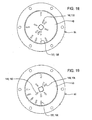
- Position 6 of the selector disk 48 is achieved by indexing the selector disk 48 clockwise through an angle of 22.5° from the 112.5° to a 135° position illustrated in Fig. 18 wherein the selector slots148 and 151 of the selector disk 48 are respectively superposed over the flow control slots 128 and 136 of the outlet section 84 of the manifold body 14.
- the flow control slot 128 is coupled in fluid communication with the outlet 122 that supplies fluid to the nozzle 34, with the tip 42 of this nozzle having a spray rate of 2 GPM
- the control slot 136 is coupled in fluid communication with the outlet 126 that supplies fluid to the nozzle 38, with the tip 46 of this nozzle having a spray rate of 4 GPM.
- the total spray rate from the spray head 12 arrangement is 6 GPM.
- Position 7 of the selector disk 48 is achieved by indexing the selector disk 48 clockwise through an angle of 22.5° from the 135° position to a 157.5° position illustrated in Fig. 19 wherein the selector slots 144, 148 and 152 of the selector disk 48 are respectively superposed over the flow control slots 130, 134 and 136 of the outlet section 84 of the manifold body 14.
- the flow control slot 130 is coupled in fluid communication with the outlet 120 that supplies fluid to the nozzle 32, with the tip 40 of this nozzle having a spray rate of 1 GPM.
- the flow control slot 134 is coupled in fluid communication with the outlet 122 that supplies fluid to the 34, with the tip 42 of this nozzle having a spray rate of 2 GPM
- the control slot 136 is coupled in fluid communication with the outlet 126 that supplies fluid to the nozzle 38, with the tip 46 of this nozzle having a spray rate of 4 GPM
- the control slot 136 is coupled in fluid communication with the outlet 126 that supplies fluid to the nozzle 38, with the tip 46 of this nozzle having a spray rate of 4 GPM.
- the total spray rate from the spray head arrangement 12 is 7 GPM.
- Position 8 of the selector disk 48 is achieved by indexing the selector disk 48 clockwise through an angle of 22.5° from the 157.5° position to an 180° position illustrated in Fig. 20 wherein the selector slot 149 of the selector disk 48 is superposed over the flow control slot 138 of the outlet section 84 of the manifold body 14.
- the flow control slot 138 is coupled in fluid communication with the outlet 124 that supplies fluid to the nozzle 38, with the tip 46 of this nozzle having a spray rate of 8 GPM.
- the total spray rate from the spray head arrangement 12 is 8 GPM.
- Position 9 of the selector disk 48 is achieved by indexing the selector disk 48 clockwise through an angle of 22.5° from the 180° position to a 202.5° position illustrated in Fig. 21 wherein the selector slots 142 and 150 of the selector disk 48 are respectively superposed over the flow control slots 128 and 138 of the outlet section 84 of the manifold body 14.
- the flow control slot 128 is coupled in fluid communication with the outlet 120 that supplies fluid to the nozzle 32 having the tip 40 which has a spray rate of 1 GPA
- the flow control slot 138 is coupled in fluid communication with the outlet 124 that supplies fluid to the nozzle 38, with the tip 46 of this nozzle having a spray rate of 8 GPM.
- the total spray rate from the spray head arrangement 12 is 9 GPM.
- Position 10 of the selector disk 48 is achieved by indexing the selector disk 48 clockwise through an angle of 22.5° from the 202.5° position to a 225° position illustrated in Fig. 22 wherein the selector slots 142 and 151 of the selector disk 48 are respectively superposed over the flow control slots 132 and 138 of the outlet section 84 of the manifold body 14.
- the flow control slot 132 is coupled in fluid communication with the outlet 122 that supplies fluid to the nozzle 34 having the tip 42 which has a spray rate of 2 GPM
- the flow control slot 138 is coupled in fluid communication with the outlet 124 that supplies fluid to the nozzle 38, with the tip 46 of this nozzle having a spray rate of 8 GPM.
- the total spray rate from the spray head arrangement 12 is 10 GPM.
- Position 11 of the selector disk 48 is achieved by indexing the selector disk 48 clockwise through an angle of 22.5° from the 225° position to a 247.5° position illustrated in Fig. 23 wherein the selector slots 142 and 146 and 152 of the selector disk 48 are respectively superposed over the flow control slots 134, 130 and 138 of the outlet section 84 of the manifold body 14.
- the flow control slot 134 is coupled in fluid communication with the outlet 122 that supplies fluid to the nozzle 34 having the tip 42 which has a spray rate of 2 GPM
- the flow control slot 130 is in fluid communication with the outlet 120 that supplies fluid to the nozzle 32 having the tip 40 which has a spray rate of 1 GPM
- the 138 is coupled in fluid communication with the outlet 124 that supplies fluid to the nozzle 38, with the tip 46 of this nozzle having a spray rate of 8 GPM.
- the total spray rate from the spray head arrangement 12 is 11 GPM.
- Position 12 of the selector disk 48 is achieved by indexing the selector disk 48 clockwise through an angle of 22.5° from the 247.5° position to a 270° position illustrated in Fig. 24 wherein the selector slot 149 of the selector disk 48 is superposed over the flow control slot 140 of the outlet section 84 of the manifold body 14.
- the flow control slot 140 is coupled in fluid communication with both outlets 124 and 126, these outlets respectively supplying fluid to the nozzles 36 and 38.
- the nozzle 36 has the spray tip 44 having the spray rate of 8 GPM, and the nozzle 38 has the spray tip 46 respectively having the spray rate of 4 GPM.
- the total spray rate from the spray head arrangement 12 is 12 GPM.
- Position 13 of the selector disk 48 is achieved by indexing the selector disk 48 clockwise through an angle of 22.5° from the 270° position to a 292.4° position illustrated in Fig. 25 wherein the selector slots148 and 150 of the selector disk 48 are respectively superposed over the flow control slots 128 and 140 of the outlet section 84 of the manifold body 14.
- the flow control slot 128 is coupled in fluid communication with the outlet 120 which supplies fluid to the nozzle 32 having the spray tip 40 having the spray rate of 1 GPM.
- the flow control slot 140 is connected in fluid communication with both of the outlets 126 and 124, with the outlet 126 supplying fluid to the nozzle 38 having the tip 46 which has the spray rate of 4 GPM and with the outlet 124 supplying fluid to the nozzle 36 having the tip 44 which has the spray rate of 8 GPM.
- the total spray rate from the spray head is 13 GPM.
- Position 14 of the selector disk 48 is achieved by indexing the selector disk 48 clockwise through an angle of 22.5° from the 292.5° position to a 215° position illustrated in Fig. 26 wherein the selector slots144 and 151 of the selector disk 48 are respectively superposed over the flow control slots132 and 140 of the outlet section 84 of the manifold body 14.
- the flow control slot 132 is coupled in fluid communication with the outlet 122 which supplies fluid to the nozzle 34 having the spray tip 42 having the spray rate of 2 GPM.
- the flow control slot 140 is connected in fluid communication with both of the outlets 126 and 124, with the outlet 126 supplying fluid to the nozzle 38 having the tip 46 which has the spray rate of 4 GPM and with the outlet 124 supplying fluid to the nozzle 36 having the tip 44 which has the spray rate of 8 GPM.
- the total spray rate from the spray head arrangement is 14 GPM.
- Position 15 of the selector disk 48 is achieved by indexing the selector disk 48 clockwise through an angle of 22.5° from the 215° position to a 237.5° position illustrated in Fig. 27 wherein the selector slots144, 148 and 152 of the selector disk 48 are respectively superposed over the flow control slots130, 134 and 140 of the outlet section 84 of the manifold body 14.
- the flow control slot 130 is coupled in fluid communication with the outlet 120 which supplies fluid to the nozzle 32 having the spray tip 40 having the spray rate of 1 GPM.
- the flow control slot 134 is connected in fluid communication with the outlet 122 which supplies fluid to the nozzle 34 having the spray tip 42 which has a spray rate of 2 GPM.
- the flow control slot 140 is connected in fluid communication with both of the outlets 126 and 124, with the outlet 126 supplying fluid to the nozzle 38 having the tip 46 which has the spray rate of 4 GPM and with the outlet 124 supplying fluid to the nozzle 36 having the tip 44 which has the spray rate of 8 GPM.
- the total spray rate from the spray head is 15 GPM.
- nozzle selector disk 48 and flow direction control plate 50 are particularly suited for making it possible to sequentially select different ones or different combinations of the nozzles 32-38 for effecting eleven ever increasing spray rates
- other selector disk control slot arrangements and outlet arrangements could be designed which would operate in accordance with the principles of the present invention to achieve satisfactory results for some spraying applications.
- selector disk control slot arrangements and outlet arrangements requiring the selector disk to be moved other tan sequentially among the "on" positions of the selector disk, even requiring the drive motor 52 to be reversed at times.
Description
- The present invention relates to a spray head arrangement for agricultural sprayers, and more specifically relates to automatically controlling the spray rate from a spray head arrangement for compensating for changes in vehicle ground speed so as to maintain a constant application rate.
- Agricultural sprayers use nozzles for spraying a liquid which may be a fertilizer, a pesticide, a fungicide, or an insecticide, for example, onto agricultural crops. Traditional nozzles consist of an orifice with geometry controlling the flow rate, droplet size and spray pattern to the target. The flow rate through the orifice is mainly a function of the orifice area and geometry as well as the fluid pressure at the orifice (i.e., pressure just prior to the orifice). Since the orifice size is fixed, i.e., the orifice geometry doesn't change, the most common way to influence the flow rate through the nozzle is by changing pressure.
- Changing the fluid pressure at the nozzle to influence flow rate changes has become common place on sprayers in order to allow for variable vehicle speed. Systems change the flow rate proportional to the vehicle speed in order to keep the application rate the same.
- However, using the traditional fixed orifice nozzle has some limitations. The pressure versus flow relationship is a squared function. To double the flow requires increasing the pressure by a factor of four times. Unfortunately, changing pressure also changes atomization dynamics resulting in an impact on spray quality. Spray quality characteristics, namely, droplet size and the spray angle, both become smaller as pressure increases. These changes can negatively impact to spray deposit and spray drift. So, the need for a variable rate nozzle with uniform pressure has emerged.
-
U.S. Patent No. 7,124,964 discloses a nozzle arrangement including a flexible spray tip which may be manipulated by a driven metering member which acts to selectively change the spray tip configuration in response to changes in vehicle speed so as to change the spray tip spray rate for maintaining a desired application rate. This nozzle arrangement has the disadvantage of requiring a specialized nozzle construction instead of less costly standard nozzle configurations. - Another spray head is known from
US 2002/0092928 . - According to the present invention, there is provided a novel spray head arrangement including a nozzle arrangement for maintaining a desired application rate.
- An object of the invention is to provide a spray head nozzle arrangement which automatically maintains a desired constant spray fluid application rate during changes in sprayer vehicle ground speed and which overcomes the above-noted disadvantages of the patented nozzle arrangement while maintaining the advantage of permitting the spray fluid to be supplied to the spray head nozzle arrangement at a constant pressure.
- This object is achieved by a spray head nozzle arrangement including a manifold body defining a cavity connected in fluid communication with a spray fluid inlet arrangement and a spray fluid outlet arrangement, with the outlet arrangement defining a plurality of passages having entrances defined as slots located in one or more circular patterns about an upright axis of rotation of a nozzle selector disk containing a plurality of slots located for being rotated into register with one or more of the entrance slots of the outlet arrangement, with the outlet arrangement leading to a plurality of standard nozzles carried by the body and respectively having spray tips designed for having different spray rates for a given pressure of the supplied spray fluid, whereby different spray rates are obtained by rotating the nozzle selector disk to different positions by a drive motor, with the drive motor being automatically controlled to rotate the nozzle selector disk to select one or more nozzles for effecting a spray rate corresponding to the spray vehicle speed so as to maintain a constant spray fluid application rate.
- In one embodiment, a spray head arrangement for use in an agricultural sprayer including a spray boom carrying a plurality of said spray heads, may comprise: a manifold body defining a fluid chamber including a bottom section having a substantially planar top surface region containing a plurality of flow control openings having inlets arranged in a circular ring-shaped zone extending about an upright axis; a plurality of nozzles respectively having inlets coupled for receiving fluid from said plurality of flow control openings; a nozzle selector disk being located in said chamber and having a flat bottom surface engaged with said planar top surface region of said bottom section. The nozzle selector disk is mounted for rotation about said axis and contains at least one nozzle selection opening located for selectively registering with said flow control openings as said disk is rotated in said chamber. A power-operated motor is connected for rotating said nozzle selector disk.
- In a further embodiment a spray head arrangement for an agricultural sprayer may comprise: a manifold body having an inlet coupled to a supply of spray fluid and a plurality of outlets respectively coupled to a plurality of nozzles mounted to the manifold body. Each nozzle might be provided with a conventional spray tip having a given spray rate at a given constant spray vehicle ground speed. Further a nozzle selector disk can be mounted in the manifold body in a location where the disk moves over control fluid inlets of a plurality of flow direction control passages respectively leading to said outlets. Said nozzle selector disk may contain a plurality of nozzle selector openings located for selectively placing said inlet in fluid communication with one or more of said flow direction control passages as the nozzle selector disk is sequentially rotated among equally spaced positions. A combination of aligned flow direction control passages and selector openings can be such that a sum of the outlet rates of the nozzles placed in fluid communication with the inlet at each equally spaced position sequentially increases. A stepper motor can be coupled to said nozzle selector disk for rotating said disk among said equally spaced positions.
- In a further embodiment a spray head arrangement for use with an agricultural sprayer may comprise: a manifold body having a supply fluid inlet adapted for connection to a supply of spray fluid, a fluid chamber connected in fluid communication with said inlet, and a fluid direction control passage arrangement connected in fluid communication with said fluid chamber. At least first, second and third spray nozzles are mounted to said manifold body and respectively including first, second and third spray tips having respective different first, second and third constant spray rates when the nozzles are supplied with a spray fluid at a predetermined constant pressure and are carried at a predetermined ground speed by a spray vehicle, with the spray tips being oriented for directing spray fluid in a downward direction from the manifold body. The control passage arrangement including a plurality of separate control fluid inlets coupled in fluid communication with said fluid chamber, and including first, second and third control fluid outlets respectively coupled to said first, second and third nozzles. A valve arrangement being located in said fluid chamber for controlling fluid flow between the supply fluid inlet and said plurality of control fluid inlets. Further a valve member is included associated with said plurality of control fluid inlets and being mounted for rotation among eight angularly spaced positions including an "off" position and seven "on" positions. The spray rates are so chosen and said control passage arrangement is so designed that a sum of the spray rates from said first, second and third nozzles increases at equal increments as the valve member is rotated from said "off" position to the seven "on" positions. Further, a power-operated motor being coupled to said valve member for selectively rotating the valve member among said "on" and "off" positions. The valve member might be a circular nozzle selector disk containing a plurality of nozzle selector openings located in continuous fluid communication with said fluid chamber and being so located relative to said plurality of control fluid inlets, that said disk permits fluid communication between said fluid chamber and said control fluid inlets only when certain ones of said plurality of nozzle selector openings are aligned with certain ones of said plurality of control fluid inlets when the disk is in one of the "on" positions. Further, some of the plurality of nozzle selector openings may be arranged in a first circular ring having the axis of rotation at its center, while a remainder of the plurality of nozzle selector openings may be arranged in a second circular ring located outside said first circular ring; and said control fluid inlets including some located for becoming aligned with said some of the plurality of nozzle selector openings, and including a remainder located for becoming aligned with said remainder of the plurality of nozzle selector openings. The power-operated motor can be an electric stepper motor. Further, said eight angularly spaced locations are equally spaced, and said stepper motor being operable for moving the valve member sequentially among said "off" and "on" positions.
- This and other objects of the invention will become apparent from a reading of the ensuing description together with the appended drawings.
-
Fig. 1 is a schematic showing a control system for automatically switching liquid spray fluid among a plurality of nozzles of a spray head for controlling the spray rate so as to maintain a constant application rate with varying travel speeds of the spray vehicle. -
Fig. 2 is a perspective view of a spray head arrangement including a switchable nozzle arrangement constructed in accordance with the present invention, but with the nozzles being removed from the nozzle connectors for the sake of simplicity. -
Fig. 3 is a vertical sectional view taken through the spray head arrangement ofFig. 2 along a first plane passing through the inlet and a second plane passing through one of the four outlets, with the planes meeting at an axis of rotation of the nozzle selector disk of the nozzle arrangement. -
Fig. 4 is a bottom view of the spray head arrangement shown inFig. 2 . -
Fig. 5 is a top view of the flow direction control section of the nozzle arrangement shown inFig. 2 . -
Fig. 6 is a top view of the nozzle selector disk shown inFig. 2 . -
Fig. 7 is a horizontal sectional view taken through the flow direction control manifold body just above the lower flow direction control section ofFig. 2 and looking downwardly and showing the fluid passage arrangement used to convey fluid from the flow direction selector slots of the selector disk to the four outlets leading to the nozzle connectors. -
Fig. 8 is a vertical sectional view taken through the lower flow direction control section of the manifold body along thelines 8 -- 8 ofFig. 7 , but with the lower portion of the upper inlet section and nozzle selector disk being removed for the sake of simplicity. -
Fig. 9 is a horizontal sectional view taken through the manifold body along thelines 9 -- 9 ofFig. 8 , but showing the entire manifold body. -
Fig. 10 is a horizontal sectional view taken through the manifold body along thelines 9 -- 9 ofFig. 7 , but showing the entire manifold body. -
Figs 11 - 26 , respectively, illustrate the sixteen positions of the nozzle selector disk for achieving each of sixteen spray rates from the spray head. -
Fig. 27 is a table showing the application rates achievable for each of the sixteen different selected positions of the nozzle selector disk shown inFigs. 11 - 26 . - Referring now to
Fig. 1 , there is shown a schematic of acontrol system 10 for maintaining the application rate of an agricultural spray to a field substantially constant at different sprayer vehicle ground speeds. Thecontrol system 10 comprises a plurality of spray head arrangements 12 (only one shown) which would be mounted in evenly spaced relationship to each other along the length of a sprayer boom (not shown). Each of thespray head arrangments 12 includes amanifold body 14 having aninlet 16 coupled for receiving spray fluid from asupply tube 18 carried by the spray boom and coupled to an outlet of asupply pump 20 having an inlet coupled to a source of spray fluid contained within aspray fluid tank 22 carried by the sprayer vehicle. Four cylindrical,tubular nozzle connectors manifold body 14 in fluid communication with four outlet openings, described below. Fourconventional spray nozzles connectors spray tips connectors - A flow control valve is defined by a circular
nozzle selector disk 48 and themanifold body 14 with thenozzle selector disk 48 being located within themanifold body 14 at a location between theinlet 16 and a flow direction control passage arrangement (described below) and is mounted for rotation about an upright axis of rotation. The flow direction control passage arrangement includes a plurality of slots (described below), which lead to and cooperate with passage ways (also described below) to define an outlet passage arrangement which lead to one or more of the nozzle connectors 24-30, and hence to one or more of the spray nozzles 32-38. - The
nozzle selector disk 48 is selectively positioned by automatic operation of a power-operated motor, which may be an electrically controlled pneumatic, hydraulic or electric motor, but is preferably an electrically poweredstepper motor 52 mounted to a central location of a top surface of themanifold body 14 and has anoutput shaft 54 coupled, in a manner described in more detail below, to a central location of thenozzle selector disk 48. Themotor 52 is electrically coupled, as by a motorcontrol signal lead 56, for receiving electrical control pulses from amotor controller 58 as commanded by anelectronic controller 60 coupled to themotor controller 56 by anoutput signal lead 62. Theelectronic controller 60 may be a microprocessor having a memory into which field mapping data, for example, relating to potential yield, soil type, soil nutrients, soil moisture content, weeds, diseases, and field topography, may be stored along with corresponding spray fluid application rates. To go along with this mapping data, aGPS receiver 64 is coupled to the controller by a positioninput signal lead 66. Also stored in the memory of thecontroller 60 is a look-up table containing data relating application rates of the nozzle tips 40-46 to ground speed of the spray vehicle. To go along with this data, a spray vehicleground speed sensor 68 is coupled to thecontroller 60 by a ground speedinput signal lead 70. The type of spraying being done and the corresponding nozzle tips being used can be keyed into the memory of thecontroller 60 by a manually-operabledata input device 72 that is coupled to the controller by adata input lead 74. - Referring now to
Figs. 2 and3 , there is shown thespray head arrangement 12 ofFig. 1 , but with the nozzles 32-38 and associated spray tips being omitted for the sake of clarity. It can be seen that thestepper motor 52 includes acylindrical housing 76 provided at its lower end with a horizontalmounting flange arrangement 78 secured against a top surface of themanifold body 14 byscrew fasteners 80. Also, it can be seen that themanifold body 14 includes an upper cylindrical sprayfluid inlet section 82 and a lower cylindrical sprayfluid outlet section 84, thesections nut combinations 86 arranged in a circular pattern. It is to be understood that, instead of the nut and boltcombinations 86, themanifold body sections 82 may be secured together in any other suitable fashion including threaded or interlocking connections, for example. - As can best be seen in
Fig. 3 , a central location of theinlet section 82 of themanifold body 14 is provided with a stepped cylindrical throughbore 88. Theoutput shaft 54 of thestepper motor 52 is disposed along a central axis of thebore 88 and is connected to thenozzle selector disk 48 by ashaft coupler 90 having ablind bore 92 extending axially from an upper end of the coupler and receiving theoutput shaft 54, with thecoupler 90 being secured for rotation with theshaft 54 by being keyed or having a splined connection (not shown) in a well known manner and being axially secured by asetscrew 94. Alower end section 96 of the shaft coupler has a non- round cross-section, which may be square or round with a flat, for example, received in a complementary shapedopening 98 located at the axial center of thedisk 48. Thecoupler 90 further includes anannular flange 100 engaging a top surface of thenozzle selector disk 48. One ormore shims 102 is (are) located on a top side of theflange 100 and takes up any space between atop surface 104 of anannular fluid chamber 106 defined by a circular recess formed in the bottom of theinlet section 82 and the top of theoutlet section 84 of themanifold body 14, thechamber 106 being in fluid communication with thespray fluid inlet 16 and extending over the top of thenozzle selector disk 48. Leakage of spray fluid from thechamber 106 along a flat interface established between theinlet section 82 and theoutlet section 84 of themanifold body 14 is prevented by an o-ring seal 108 located in an annular seal groove provided in the underside of theinlet section 82 outwardly of thechamber 106. Leakage of fluid along an annular interface between theshaft coupler 90 and the surface of throughbore 88 is prevented by a low friction,annular shaft seal 110 located in anannular seal receptacle 112 defined by the throughbore 88. An annularseal retainer plate 114 engages a top surface of theshaft seal 110 and is supported on anannular step surface 116 defined by throughbore 88. Theretainer plate 114 is held in place by asnap ring 118 that is received in an annular snap ring groove provided in a surrounding wall region of the throughbore 88. Referring now also toFig. 4 , it can be seen that the bottom of theoutlet section 84 of themanifold body 14 includesoutlets tubular nozzle connectors - Referring now to
Fig. 5 , it can be seen that theoutlet section 84 of the manifold 14 contains an arrangement of flow control slots. Considering a vertical line through the center of the plate to be the loci of a 0° position at the bottom of theoutlet section 84 and a 180° position at the top of thesection 84, then, proceeding clockwise, first, second, third and fourthflow control slots outlet section 84 in an inner ring or circular arrangement of locations at 0°, 45°, 202.5° and 225°, while fifth, sixth, seventh and eighthflow control slots - Referring now to
Fig. 6 , it can be seen that thenozzle selector disk 48 contains an arrangement of nozzle selector slots. Assuming that thedisk 48 is rotated in a clockwise direction for sequencing between positions for effecting increasing spray rates from thespray head arrangement 12, the position illustrated is that for preventing flow to all of the flow control slots of theoutlet section 84. In this zero flow or "off" position, first, second, third and fourthnozzle selector slots disk 48 in an inner ring of locations which lead the 0° location of theoutlet section 84 of the manifold 14 by respective angles of 22.5°, 112.5°, 202.5° and 292.5°, while fifth, sixth, seventh and eighthnozzle selector slots - Referring now back to
Fig. 2 and also toFigs. 7 and 8 , it can be seen that theoutlet section 84 of themanifold body 14 includes first, second, and third horizontal, parallel blind bores 154, 156 and 158, respectively, extending horizontally from a right side, upper level region of theoutlet section 84 and making right angles with a vertical plane P passing through the center of thesection 84, with theoutlets outlets Fig. 9 , the blind bores 154, 156 and 158, respectively, have right end portions sealed by first, second and third threadedplugs spray fluid outlets lower section 84 of themanifold body 14. A fourth horizontalblind bore 166 is also located in the upper level of theoutlet section 84 of themanifold body 14, the bore166 intersecting an upper end region of thespray fluid outlet 124 and being oriented so as to intersect and traverse the plane P, with thebore 166 making an angle of approximately 45° with the plane P. A left end portion of theblind bore 166 is provided with a fourth threadedplug 168. Theblind bore 166 includes a reduceddiameter section 170 beginning at a location between where thebore 166 intersects theflow control outlet 124 and the plane P resulting in an annular shoulder being formed which defines avalve seat 172 for a one-waycheck valve ball 174 having a purpose discussed below. Referring now also toFig. 10 , it can be seen that a fifth horizontalblind bore 176 is located at a second level in the lowermanifold body section 84 which is below the first level in which thebores blind bore 176 being centered along the plane P, with an end region of thebore 176 being disposed vertically beneath an end region of thefourth bore 166 which traverses the plane P. As viewed inFig. 7 , a bottom end portion of the bore contains a threadedplug 178. Thebore 176 is stepped so as to have a reduced diameterupper end section 180 resulting in a shoulder which defines avalve seat 182 for a one-waycheck valve ball 184 having a purpose discussed below. - As can best be seen in
Figs 7, 8 and9 , of the four flowdirection control slots outlet section 84, theslots blind bore 154, and hence theoutlet 120, while theslots blind bore 156, and hence with theoutlet 122. The threeflow control slots outlet section 84, with theslot 136 intersecting the blind bores 158 and 176, theslot 138 intersecting the large diameter section of theblind bore 166, and with theslot 140 intersecting the reduceddiameter sections slot 136 is in fluid communication with theoutlet 126, noting that thecheck ball 184 prevents flow to any other outlet, theslot 138 is connected in fluid communication with theoutlet 124, noting that thecheck ball 174 prevents flow to any other outlet, and theslot 140 is coupled in fluid communication with bothoutlets check ball 184 permits flow to theoutlet 126 by way of thebore 176,slot 136 and bore 158. - Referring now to
Fig. 11 , there is shown a table correlating sixteen selection positions of thenozzle selector disk 48 which are respectively attained by indexing theselector disk 48 clockwise through 22.5° increments from the 0 or "off" position shown inFig. 6 . Also listed is four nozzle spray rates of 1, 2, 4 and 8 gallons per minute (GPM) respectively produced by the fourtips nozzles outlets - Accordingly, with the
nozzle selector disk 48 in the 0 or "off" disk position the disk is in a disk angle of rotation of 0° wherein none of the flow direction control slots 128-140 at the top of theoutlet section 84 of themanifold body 14 are selected, i.e., in alignment with any of the nozzle selection slots 142-152 of theselector disk 48. Consequently, the sum of the nozzle flow rates when theselector disk 48 is in the "off" position is 0 gallons per minute (GPM). This relationship between theselector disk 48 andoutlet section 84 is illustrated inFig. 12 . -
Position 1 of theselector disk 48 is achieved by indexing theselector disk 48 clockwise relative to theoutlet section 84 through an angle of 22.5° from the 0° position, to the position illustrated inFig. 13 wherein theselector slot 142 of theselector disk 48 is superposed over theflow control slot 128 of theoutlet section 84 of themanifold body 14. As described above, theflow control slot 128 is coupled in fluid communication with theoutlet 120 that supplies fluid to thenozzle 32, with thetip 40 of this nozzle having a spray rate of 1 GPM. -
Position 2 of theselector disk 48 is achieved by indexing theselector disk 48 clockwise through an angle of 22.5° from the 22.5° position, to a 45° position illustrated inFig. 14 wherein theselector slot 146 of theselector disk 48 is superposed over theflow control slot 132 of theoutlet section 84 of themanifold body 14. As described above, theflow control slot 132 is coupled in fluid communication with theoutlet 122 that supplies fluid to thenozzle 34, with the tip of thisnozzle 42 having a spray rate of 2 GPM. -
Position 3 of theselector disk 48 is achieved by indexing theselector disk 48 clockwise through an angle of 22.5° from the 45° position, to a 67.5° position illustrated inFig. 15 wherein the selector slots142 and 146 of theselector disk 48 are respectively superposed over theflow control slots outlet section 84 of themanifold body 14. As described above, theflow control slot 130 is coupled in fluid communication with theoutlet 120 that supplies fluid to thenozzle 32, this nozzle having thetip 40 having a spray rate of 1 GPM. Theflow control slot 134 is coupled in fluid communication with theoutlet 122 which is coupled to thenozzle 34, with thetip 42 of this nozzle having a spray rate of 2 GPM. Thus, the sum of the spray rates from thespray head arrangement 12 is 3 GPM. -
Position 4 of theselector disk 48 is achieved by indexing theselector disk 48 clockwise through an angle of 22.5° from the 67.5° position, to a 90° position illustrated inFig. 16 wherein theselector slot 149 of theselector disk 48 is superposed over theflow control slot 136 of theoutlet section 84 of themanifold body 14. As described above, theflow control slot 136 is coupled in fluid communication with theoutlet 126 that supplies fluid to thenozzle 38, with thetip 46 of this nozzle having a spray rate of 4 GPM. Thus, the spray rate from thespray head arrangement 12 is 4 GPM. -
Position 5 of theselector disk 48 is achieved by indexing theselector disk 48 clockwise through an angle of 22.5° from the 90° position, to a 112.5° position illustrated inFig. 17 wherein the selector slots144 and 150 of theselector disk 48 are respectively superposed over theflow control slots outlet section 84 of themanifold body 14. As described above, theflow control slot 128 is coupled in fluid communication with theoutlet 120 that supplies fluid to thenozzle 32, with thetip 40 of this nozzle having a spray rate of 1 GPM, and thecontrol slot 136 is coupled in fluid communication with theoutlet 126 that supplies fluid to thenozzle 38, with thetip 46 of this nozzle having a spray rate of 4 GPM. Thus, the total spray rate from thespray head arrangement 12 is 5 GPM. -
Position 6 of theselector disk 48 is achieved by indexing theselector disk 48 clockwise through an angle of 22.5° from the 112.5° to a 135° position illustrated inFig. 18 wherein the selector slots148 and 151 of theselector disk 48 are respectively superposed over theflow control slots outlet section 84 of themanifold body 14. As described above, theflow control slot 128 is coupled in fluid communication with theoutlet 122 that supplies fluid to thenozzle 34, with thetip 42 of this nozzle having a spray rate of 2 GPM, and thecontrol slot 136 is coupled in fluid communication with theoutlet 126 that supplies fluid to thenozzle 38, with thetip 46 of this nozzle having a spray rate of 4 GPM. Thus, the total spray rate from thespray head 12 arrangement is 6 GPM. -
Position 7 of theselector disk 48 is achieved by indexing theselector disk 48 clockwise through an angle of 22.5° from the 135° position to a 157.5° position illustrated inFig. 19 wherein theselector slots selector disk 48 are respectively superposed over theflow control slots outlet section 84 of themanifold body 14. As described above, theflow control slot 130 is coupled in fluid communication with theoutlet 120 that supplies fluid to thenozzle 32, with thetip 40 of this nozzle having a spray rate of 1 GPM. Theflow control slot 134 is coupled in fluid communication with theoutlet 122 that supplies fluid to the 34, with thetip 42 of this nozzle having a spray rate of 2 GPM, and thecontrol slot 136 is coupled in fluid communication with theoutlet 126 that supplies fluid to thenozzle 38, with thetip 46 of this nozzle having a spray rate of 4 GPM, and thecontrol slot 136 is coupled in fluid communication with theoutlet 126 that supplies fluid to thenozzle 38, with thetip 46 of this nozzle having a spray rate of 4 GPM. Thus, the total spray rate from thespray head arrangement 12 is 7 GPM. -
Position 8 of theselector disk 48 is achieved by indexing theselector disk 48 clockwise through an angle of 22.5° from the 157.5° position to an 180° position illustrated inFig. 20 wherein theselector slot 149 of theselector disk 48 is superposed over theflow control slot 138 of theoutlet section 84 of themanifold body 14. As described above, theflow control slot 138 is coupled in fluid communication with theoutlet 124 that supplies fluid to thenozzle 38, with thetip 46 of this nozzle having a spray rate of 8 GPM. Thus, the total spray rate from thespray head arrangement 12 is 8 GPM. -
Position 9 of theselector disk 48 is achieved by indexing theselector disk 48 clockwise through an angle of 22.5° from the 180° position to a 202.5° position illustrated inFig. 21 wherein theselector slots selector disk 48 are respectively superposed over theflow control slots outlet section 84 of themanifold body 14. As described above, theflow control slot 128 is coupled in fluid communication with theoutlet 120 that supplies fluid to thenozzle 32 having thetip 40 which has a spray rate of 1 GPA, and theflow control slot 138 is coupled in fluid communication with theoutlet 124 that supplies fluid to thenozzle 38, with thetip 46 of this nozzle having a spray rate of 8 GPM. Thus, the total spray rate from thespray head arrangement 12 is 9 GPM. -
Position 10 of theselector disk 48 is achieved by indexing theselector disk 48 clockwise through an angle of 22.5° from the 202.5° position to a 225° position illustrated inFig. 22 wherein theselector slots 142 and 151 of theselector disk 48 are respectively superposed over theflow control slots outlet section 84 of themanifold body 14. As described above, theflow control slot 132 is coupled in fluid communication with theoutlet 122 that supplies fluid to thenozzle 34 having thetip 42 which has a spray rate of 2 GPM, and theflow control slot 138 is coupled in fluid communication with theoutlet 124 that supplies fluid to thenozzle 38, with thetip 46 of this nozzle having a spray rate of 8 GPM. Thus, the total spray rate from thespray head arrangement 12 is 10 GPM. -
Position 11 of theselector disk 48 is achieved by indexing theselector disk 48 clockwise through an angle of 22.5° from the 225° position to a 247.5° position illustrated inFig. 23 wherein theselector slots selector disk 48 are respectively superposed over theflow control slots outlet section 84 of themanifold body 14. As described above, theflow control slot 134 is coupled in fluid communication with theoutlet 122 that supplies fluid to thenozzle 34 having thetip 42 which has a spray rate of 2 GPM, theflow control slot 130 is in fluid communication with theoutlet 120 that supplies fluid to thenozzle 32 having thetip 40 which has a spray rate of 1 GPM, and the 138 is coupled in fluid communication with theoutlet 124 that supplies fluid to thenozzle 38, with thetip 46 of this nozzle having a spray rate of 8 GPM. Thus, the total spray rate from thespray head arrangement 12 is 11 GPM. -
Position 12 of theselector disk 48 is achieved by indexing theselector disk 48 clockwise through an angle of 22.5° from the 247.5° position to a 270° position illustrated inFig. 24 wherein theselector slot 149 of theselector disk 48 is superposed over theflow control slot 140 of theoutlet section 84 of themanifold body 14. As described above, theflow control slot 140 is coupled in fluid communication with bothoutlets nozzles nozzle 36 has thespray tip 44 having the spray rate of 8 GPM, and thenozzle 38 has thespray tip 46 respectively having the spray rate of 4 GPM. Thus, the total spray rate from thespray head arrangement 12 is 12 GPM. -
Position 13 of theselector disk 48 is achieved by indexing theselector disk 48 clockwise through an angle of 22.5° from the 270° position to a 292.4° position illustrated inFig. 25 wherein the selector slots148 and 150 of theselector disk 48 are respectively superposed over theflow control slots outlet section 84 of themanifold body 14. As described above, theflow control slot 128 is coupled in fluid communication with theoutlet 120 which supplies fluid to thenozzle 32 having thespray tip 40 having the spray rate of 1 GPM. Theflow control slot 140 is connected in fluid communication with both of theoutlets outlet 126 supplying fluid to thenozzle 38 having thetip 46 which has the spray rate of 4 GPM and with theoutlet 124 supplying fluid to thenozzle 36 having thetip 44 which has the spray rate of 8 GPM. Thus, the total spray rate from the spray head is 13 GPM. -
Position 14 of theselector disk 48 is achieved by indexing theselector disk 48 clockwise through an angle of 22.5° from the 292.5° position to a 215° position illustrated inFig. 26 wherein the selector slots144 and 151 of theselector disk 48 are respectively superposed over the flow control slots132 and 140 of theoutlet section 84 of themanifold body 14. As described above, theflow control slot 132 is coupled in fluid communication with theoutlet 122 which supplies fluid to thenozzle 34 having thespray tip 42 having the spray rate of 2 GPM. Theflow control slot 140 is connected in fluid communication with both of theoutlets outlet 126 supplying fluid to thenozzle 38 having thetip 46 which has the spray rate of 4 GPM and with theoutlet 124 supplying fluid to thenozzle 36 having thetip 44 which has the spray rate of 8 GPM. Thus, the total spray rate from the spray head arrangement is 14 GPM. -
Position 15 of theselector disk 48 is achieved by indexing theselector disk 48 clockwise through an angle of 22.5° from the 215° position to a 237.5° position illustrated inFig. 27 wherein the selector slots144, 148 and 152 of theselector disk 48 are respectively superposed over the flow control slots130, 134 and 140 of theoutlet section 84 of themanifold body 14. As described above, theflow control slot 130 is coupled in fluid communication with theoutlet 120 which supplies fluid to thenozzle 32 having thespray tip 40 having the spray rate of 1 GPM. Theflow control slot 134 is connected in fluid communication with theoutlet 122 which supplies fluid to thenozzle 34 having thespray tip 42 which has a spray rate of 2 GPM. Theflow control slot 140 is connected in fluid communication with both of theoutlets outlet 126 supplying fluid to thenozzle 38 having thetip 46 which has the spray rate of 4 GPM and with theoutlet 124 supplying fluid to thenozzle 36 having thetip 44 which has the spray rate of 8 GPM. Thus, the total spray rate from the spray head is 15 GPM. - It is to be understood that, while the
nozzle selector disk 48 and flow direction control plate 50 are particularly suited for making it possible to sequentially select different ones or different combinations of the nozzles 32-38 for effecting eleven ever increasing spray rates, other selector disk control slot arrangements and outlet arrangements could be designed which would operate in accordance with the principles of the present invention to achieve satisfactory results for some spraying applications. Additionally, it is to be understood that, for some spray application rates, it might be expedient to provide selector disk control slot arrangements and outlet arrangements requiring the selector disk to be moved other tan sequentially among the "on" positions of the selector disk, even requiring thedrive motor 52 to be reversed at times. - Having described the preferred embodiment, it will become apparent that various modifications can be made without departing from the scope of the invention as defined in the accompanying claims.
Claims (6)
- A spray head arrangement (12) for use in an agricultural sprayer including a spray boom carrying a plurality of said spray head arrangements, comprising: a manifold body (14) defining a fluid chamber (106) including a bottom section having a substantially planar top surface region (104) containing a plurality of flow control openings (128, 130, 132, 134, 136, 138, 140) having inlets arranged in a circular ring-shaped zone extending about an upright axis; a plurality of nozzles (32, 34, 36, 38) respectively having inlets coupled for receiving fluid from said plurality of flow control openings (128, 130, 132, 134, 136, 138, 140); a nozzle selector disk (48) being located in said chamber (106) and having a flat bottom surface engaged with said planar top surface region (104) of said bottom section, said nozzle selector disk (48) being mounted for rotation about said axis and containing at least one nozzle selection opening (142, 144, 146, 148, 149, 150, 151, 152) located for selectively registering with said flow control openings (128, 130, 132, 134, 136, 138, 140) as said disk (48) is rotated in said chamber (106); and a power-operated motor being connected for rotating said nozzle selector disk (48).
- The spray head arrangement (12), as defined in claim 1, wherein said plurality of flow control openings (128, 130, 132, 134, 136, 138, 140) include at least one flow control opening (128, 130, 132, 134, 136, 138, 140) located in a second circular ring-shaped zone located concentric to said first-mentioned ring-shaped zone; and said control disk (48) contains at least a second nozzle selection opening (142, 144, 146, 148, 149, 150, 151, 152) located for coming into register with said at least one flow control opening (128, 130, 132, 134, 136, 138, 140), with said plurality of flow control openings (128, 130, 132, 134, 136, 138, 140) being so located relative to each other that inlets of at least two of said plurality of nozzles are simultaneously coupled for receiving fluid from said fluid chamber (106) when said control disk (48) is in a preselected location relative to said flow control openings (128, 130, 132, 134, 136, 138, 140).
- The spray head arrangement (12), as defined in claim 1 or 2, wherein said plurality of nozzles (32, 34, 36, 38) comprise first, second, third and fourth nozzles.
- The spray head arrangement (12), as defined in one of the claims 1 to 3, wherein the spray tip capacity of the first nozzle (32, 34, 36, 38), at a constant supply pressure, is n GPA, the spray tip capacity of the second nozzle (32, 34, 36, 38) is 2n GPM, the spray tip capacity of the third nozzle (32, 34, 36, 38) is 4n GPM and the spray tip capacity of the fourth nozzle (32, 34, 36, 38) is 8n GPA, with the plurality of nozzle selection openings (142, 144, 146, 148, 149, 150, 151, 152) being so located in the nozzle selection disk (48) and the flow control openings (128, 130, 132, 134, 136, 138, 140) being so located in the bottom section of the fluid manifold (14) that by indexing the nozzle selection disk (48) sequentially among sixteen given positions separated from each other by 22.5° results in the sum of the tip capacities of said first, second, third and four nozzles (32, 34, 36, 38) respectively increasing in sixteen equal increments from 0n GPM to 15n GPM.
- The spray head arrangement (12), as defined in one of the claims 1 to 3, wherein said power-operated motor is an electric motor.
- The spray head arrangement (12), as defined in claim 5, wherein said electric motor is a stepper motor (52).
Applications Claiming Priority (1)
| Application Number | Priority Date | Filing Date | Title |
|---|---|---|---|
| US13/333,178 US8919676B2 (en) | 2011-12-21 | 2011-12-21 | Arrangement for switching nozzles on the go for controlling spray rate |
Publications (2)
| Publication Number | Publication Date |
|---|---|
| EP2606722A1 EP2606722A1 (en) | 2013-06-26 |
| EP2606722B1 true EP2606722B1 (en) | 2014-09-24 |
Family
ID=47428511
Family Applications (1)
| Application Number | Title | Priority Date | Filing Date |
|---|---|---|---|
| EP20120195874 Active EP2606722B1 (en) | 2011-12-21 | 2012-12-06 | Spray head arrangement |
Country Status (8)
| Country | Link |
|---|---|
| US (1) | US8919676B2 (en) |
| EP (1) | EP2606722B1 (en) |
| CN (1) | CN103170417B (en) |
| AR (1) | AR089366A1 (en) |
| AU (1) | AU2012265592B2 (en) |
| BR (1) | BR102012032806B1 (en) |
| CA (1) | CA2798800C (en) |
| RU (1) | RU2012153578A (en) |
Families Citing this family (43)
| Publication number | Priority date | Publication date | Assignee | Title |
|---|---|---|---|---|
| US9266124B2 (en) | 2012-04-27 | 2016-02-23 | Deere & Company | Sprayer nozzle cartridge |
| US9113591B2 (en) | 2012-06-18 | 2015-08-25 | Raven Industries, Inc. | Implement for adjustably metering an agricultural field input according to different frame sections |
| US11160204B2 (en) | 2013-03-15 | 2021-11-02 | Raven Industries, Inc. | Localized product injection system for an agricultural sprayer |
| FR3005877B1 (en) * | 2013-05-22 | 2018-01-19 | Exel Industries | NOZZLE SUPPORT DEVICE WITH ROTATING NOZZLE HEAD |
| CA2926448C (en) | 2013-10-17 | 2020-09-22 | Raven Industries, Inc. | Nozzle control system and method |
| US10173236B2 (en) | 2013-10-17 | 2019-01-08 | Raven Industries, Inc. | Nozzle control system and method |
| CN105764328B (en) * | 2013-10-29 | 2020-01-10 | 凯特克控股私人有限公司 | Sprinkler head |
| US9675000B2 (en) | 2014-05-09 | 2017-06-13 | Raven Industries, Inc. | Optical flow sensing application in agricultural vehicles |
| US10189031B2 (en) | 2014-06-20 | 2019-01-29 | Deere & Company | Hybrid flow nozzle and control system |
| AU2015203208B2 (en) * | 2014-06-20 | 2017-04-13 | Deere & Company | Hybrid flow nozzle and control system |
| US10773271B2 (en) | 2014-06-20 | 2020-09-15 | Deere & Company | Time varying control of the operation of spray systems |
| US9884330B2 (en) | 2014-06-20 | 2018-02-06 | Deere & Company | Broadband spray nozzle systems and methods |
| USD766399S1 (en) | 2014-10-03 | 2016-09-13 | Deere & Company | Hybrid spray nozzle turret |
| EP3280539B1 (en) * | 2015-04-09 | 2019-02-13 | Husqvarna AB | Spray head and spraying apparatus |
| US10518284B2 (en) | 2015-08-04 | 2019-12-31 | Intelligent Agricultural Solutions Llc | Interactive liquid spraying system and method |
| CN105771136B (en) * | 2016-04-07 | 2018-11-20 | 扬州智创企业运营管理服务有限公司 | A kind of cycle type applicator switching device |
| EP3565398A4 (en) | 2017-01-05 | 2020-07-15 | Raven Industries, INC. | Configurable nozzle assembly and methods for same |
| CN106954402B (en) * | 2017-04-14 | 2024-01-26 | 河南科技大学 | Quick-replacement type three-liquid/gas line magnetic coupling execution component for crop cultivation |
| CN107606281A (en) * | 2017-10-17 | 2018-01-19 | 厦门建霖健康家居股份有限公司 | A kind of electric control outlet device of touch |
| DE102018214606A1 (en) * | 2018-08-29 | 2020-03-05 | Robert Bosch Gmbh | Process for delivering a treatment liquid to an agricultural area |
| US11051505B2 (en) | 2018-10-12 | 2021-07-06 | Deere & Company | Multi-fluid spray system and method for agricultural product application |
| US10842143B2 (en) * | 2018-10-12 | 2020-11-24 | Deere & Company | Multi-fluid spray system and method for agricultural product application |
| US11292449B2 (en) * | 2018-10-19 | 2022-04-05 | GEOSAT Aerospace & Technology | Unmanned ground vehicle and method for operating unmanned ground vehicle |
| US11470834B2 (en) * | 2018-10-31 | 2022-10-18 | Spraying Systems Co. | Boom mounted spray nozzle assembly with multi check valve compact design |
| CN109430009B (en) * | 2018-11-02 | 2020-12-11 | 温州锦瑞建设有限公司 | Municipal garden irrigation equipment |
| CN109692762B (en) * | 2019-01-25 | 2024-02-27 | 九牧厨卫股份有限公司 | Spraying core and particle spraying water device |
| GB2582363B (en) * | 2019-03-21 | 2023-04-05 | Exel Ind Sa | Pressure sprayer nozzles |
| DE102019208075A1 (en) * | 2019-06-04 | 2020-12-10 | Robert Bosch Gmbh | Spray device for dispensing liquids |
| US11612160B2 (en) | 2019-10-04 | 2023-03-28 | Raven Industries, Inc. | Valve control system and method |
| WO2021140528A1 (en) * | 2020-01-10 | 2021-07-15 | Jain Irrigation Systems Limited | Fluid spray system with orifices |
| US11723354B2 (en) | 2020-03-18 | 2023-08-15 | Cnh Industrial America Llc | System and method to mitigate boom assembly movement |
| CN112273354B (en) * | 2020-10-30 | 2022-03-01 | 安徽世纪绿药生态农林有限公司 | Root of kudzu vine is planted and is used pesticide sprinkler |
| CN112690265B (en) * | 2020-12-24 | 2022-09-06 | 吉林农业大学 | Timed pesticide spraying device and method for pest control |
| CN112742614B (en) * | 2020-12-25 | 2022-03-18 | 江苏绿之源生态建设有限公司 | Multi-port spray head and spraying device for vegetation nutrient medium |
| CN112808485A (en) * | 2021-02-04 | 2021-05-18 | 广东龙丰精密铜管有限公司 | Copper pipe flaw detection ink-jet double-spray gun device and control system thereof |
| CN113509578A (en) * | 2021-05-19 | 2021-10-19 | 长江师范学院 | Site environment epidemic prevention disinfection method |
| CN113509577B (en) * | 2021-05-19 | 2023-04-25 | 长江师范学院 | Mechanical arm for disinfection and special trolley for environment disinfection thereof |
| CN113606376B (en) * | 2021-08-05 | 2023-08-18 | 江西理工大学 | Soft pneumatic valve with paper folding structure and control method thereof |
| CN113578581B (en) * | 2021-09-30 | 2021-12-10 | 江苏信美医学工程科技有限公司 | Antirust agent spraying device for medical instrument |
| CN114176060B (en) * | 2021-11-30 | 2023-02-28 | 徐州腾尔盛机械设备科技有限公司 | Agricultural injection device |
| CN114210158B (en) * | 2021-12-24 | 2023-05-23 | 昆明中天达玻璃钢开发有限公司 | Glass fiber reinforced plastic spray tower |
| CN114433372A (en) * | 2022-02-17 | 2022-05-06 | 安徽理工大学 | Dust fall nozzle for underground coal mine |
| CN115415070B (en) * | 2022-07-28 | 2023-12-19 | 东风柳州汽车有限公司 | Atomizer replacement method, device, equipment and storage medium for spraying system |
Family Cites Families (17)
| Publication number | Priority date | Publication date | Assignee | Title |
|---|---|---|---|---|
| FR2290254A1 (en) | 1974-11-07 | 1976-06-04 | Lestradet M C J | SPRAYING DEVICE FOR SPREADING RAMP INTENDED IN PARTICULAR FOR AGRICULTURAL VEHICLES |
| US5312045A (en) * | 1993-02-01 | 1994-05-17 | John Blue Company | Liquid metering distributor for agricultural chemicals |
| CA2238440C (en) | 1995-12-15 | 2004-07-27 | Kimberly-Clark Worldwide, Inc. | High temperature, high speed rotary valve |
| NO313782B1 (en) * | 1996-02-16 | 2002-12-02 | Jan Kore Hatloe | Device for periodic injection of liquid fertilizer |
| US5911363A (en) * | 1997-03-10 | 1999-06-15 | Spratronics, Inc. | Vehicle mounted spray apparatus and method |
| CN2316041Y (en) * | 1997-12-12 | 1999-04-28 | 施兆登 | Vehicle-driven sprayer |
| US5971294A (en) * | 1997-12-17 | 1999-10-26 | Agco Corp. | Agricultural application systems with improved spray control |
| US6237859B1 (en) * | 1999-09-14 | 2001-05-29 | Orchard-Rite Ltd., Inc. | Fluid injection spray system for a wind machine |
| CN2389013Y (en) * | 1999-09-29 | 2000-07-26 | 盐城市农业机械技术推广站 | High-efficient motor-driven sprayer matched with four-wheel tractor |
| IT1314504B1 (en) * | 2000-03-02 | 2002-12-18 | Cozzani Mario S R L | VALVE FOR THE CONTROL OF LARGE SECTION FLOWS, IN PARTICULAR FOR COMPRESSORS OR SIMILAR. |
| US6435427B1 (en) | 2001-01-16 | 2002-08-20 | Coltec Industries, Inc. | Nozzle assembly with an extendable turret |
| US7124964B2 (en) | 2002-09-13 | 2006-10-24 | Quy Duc Bui | Nozzle with flow rate and droplet size control capability |
| DE102004056867A1 (en) * | 2004-11-25 | 2006-06-01 | John Deere Fabriek Horst B.V. | nozzle device |
| JP5619613B2 (en) * | 2007-11-09 | 2014-11-05 | オ クォン,チョン | Multi-color paint applicator |
| US8061631B2 (en) | 2008-04-15 | 2011-11-22 | Mordechai Lev | Showerhead with multimodal operation |
| CN201543534U (en) * | 2009-10-27 | 2010-08-11 | 邓芝平 | Novel ejection gun |
| US20120187219A1 (en) * | 2011-01-26 | 2012-07-26 | Criscione Ii Frank J | Rotary pulsating valve and method for discharging fluid |
-
2011
- 2011-12-21 US US13/333,178 patent/US8919676B2/en active Active
-
2012
- 2012-12-06 EP EP20120195874 patent/EP2606722B1/en active Active
- 2012-12-11 RU RU2012153578/13A patent/RU2012153578A/en not_active Application Discontinuation
- 2012-12-14 CA CA2798800A patent/CA2798800C/en active Active
- 2012-12-19 AU AU2012265592A patent/AU2012265592B2/en active Active
- 2012-12-20 CN CN201210559092.8A patent/CN103170417B/en active Active
- 2012-12-20 BR BR102012032806-2A patent/BR102012032806B1/en active IP Right Grant
- 2012-12-20 AR ARP120104866 patent/AR089366A1/en unknown
Also Published As
| Publication number | Publication date |
|---|---|
| RU2012153578A (en) | 2014-06-20 |
| EP2606722A1 (en) | 2013-06-26 |
| BR102012032806B1 (en) | 2019-04-16 |
| AR089366A1 (en) | 2014-08-20 |
| BR102012032806A2 (en) | 2013-11-26 |
| US8919676B2 (en) | 2014-12-30 |
| CA2798800C (en) | 2020-07-07 |
| AU2012265592A1 (en) | 2013-07-11 |
| CN103170417B (en) | 2017-03-01 |
| CN103170417A (en) | 2013-06-26 |
| CA2798800A1 (en) | 2013-06-21 |
| US20130161419A1 (en) | 2013-06-27 |
| AU2012265592B2 (en) | 2017-04-13 |
Similar Documents
| Publication | Publication Date | Title |
|---|---|---|
| EP2606722B1 (en) | Spray head arrangement | |
| CA2798830C (en) | Sprayer pulsing nozzle flow control using rotational step positions | |
| US10624257B2 (en) | Controlling application rates in liquid applicators | |
| US9266124B2 (en) | Sprayer nozzle cartridge | |
| US10232395B2 (en) | Multi-nozzle rotary sprinkler | |
| EP2834013B1 (en) | Method of controlling a rotary sprinkler | |
| CA2813356A1 (en) | Sprayer nozzle apparatus | |
| US20150115058A1 (en) | Sprayer nozzle system for variable application rates | |
| US6318645B1 (en) | Variable rate flow divider | |
| US20240099288A1 (en) | Parameter sensing for a liquid applicator | |
| US20150257334A1 (en) | Flow monitoring and control system for agricultural implements | |
| CN210971544U (en) | Variable spraying shower nozzle device and plant protection unmanned aerial vehicle | |
| US4760963A (en) | Ground spray applicator | |
| JPH0657440U (en) | Rotary nozzle gun | |
| WO2003011022A1 (en) | System for spraying pesticide or similar fluids on agricultural fields, sprraying nozzle, method of spraying and use thereof | |
| JPH05261318A (en) | Multi-jet orifice spray nozzle of self-propelled spray machine |
Legal Events
| Date | Code | Title | Description |
|---|---|---|---|
| AK | Designated contracting states |
Kind code of ref document: A1 Designated state(s): AL AT BE BG CH CY CZ DE DK EE ES FI FR GB GR HR HU IE IS IT LI LT LU LV MC MK MT NL NO PL PT RO RS SE SI SK SM TR |
|
| AX | Request for extension of the european patent |
Extension state: BA ME |
|
| PUAI | Public reference made under article 153(3) epc to a published international application that has entered the european phase |
Free format text: ORIGINAL CODE: 0009012 |
|
| 17P | Request for examination filed |
Effective date: 20140102 |
|
| RBV | Designated contracting states (corrected) |
Designated state(s): AL AT BE BG CH CY CZ DE DK EE ES FI FR GB GR HR HU IE IS IT LI LT LU LV MC MK MT NL NO PL PT RO RS SE SI SK SM TR |
|
| GRAP | Despatch of communication of intention to grant a patent |
Free format text: ORIGINAL CODE: EPIDOSNIGR1 |
|
| INTG | Intention to grant announced |
Effective date: 20140411 |
|
| GRAS | Grant fee paid |
Free format text: ORIGINAL CODE: EPIDOSNIGR3 |
|
| GRAA | (expected) grant |
Free format text: ORIGINAL CODE: 0009210 |
|
| AK | Designated contracting states |
Kind code of ref document: B1 Designated state(s): AL AT BE BG CH CY CZ DE DK EE ES FI FR GB GR HR HU IE IS IT LI LT LU LV MC MK MT NL NO PL PT RO RS SE SI SK SM TR |
|
| REG | Reference to a national code |
Ref country code: GB Ref legal event code: FG4D |
|
| REG | Reference to a national code |
Ref country code: CH Ref legal event code: EP |
|
| REG | Reference to a national code |
Ref country code: AT Ref legal event code: REF Ref document number: 688193 Country of ref document: AT Kind code of ref document: T Effective date: 20141015 |
|
| REG | Reference to a national code |
Ref country code: IE Ref legal event code: FG4D |
|
| REG | Reference to a national code |
Ref country code: DE Ref legal event code: R096 Ref document number: 602012003198 Country of ref document: DE Effective date: 20141106 |
|
| PG25 | Lapsed in a contracting state [announced via postgrant information from national office to epo] |
Ref country code: LT Free format text: LAPSE BECAUSE OF FAILURE TO SUBMIT A TRANSLATION OF THE DESCRIPTION OR TO PAY THE FEE WITHIN THE PRESCRIBED TIME-LIMIT Effective date: 20140924 Ref country code: SE Free format text: LAPSE BECAUSE OF FAILURE TO SUBMIT A TRANSLATION OF THE DESCRIPTION OR TO PAY THE FEE WITHIN THE PRESCRIBED TIME-LIMIT Effective date: 20140924 Ref country code: NO Free format text: LAPSE BECAUSE OF FAILURE TO SUBMIT A TRANSLATION OF THE DESCRIPTION OR TO PAY THE FEE WITHIN THE PRESCRIBED TIME-LIMIT Effective date: 20141224 Ref country code: GR Free format text: LAPSE BECAUSE OF FAILURE TO SUBMIT A TRANSLATION OF THE DESCRIPTION OR TO PAY THE FEE WITHIN THE PRESCRIBED TIME-LIMIT Effective date: 20141225 Ref country code: FI Free format text: LAPSE BECAUSE OF FAILURE TO SUBMIT A TRANSLATION OF THE DESCRIPTION OR TO PAY THE FEE WITHIN THE PRESCRIBED TIME-LIMIT Effective date: 20140924 |
|
| REG | Reference to a national code |
Ref country code: LT Ref legal event code: MG4D Ref country code: NL Ref legal event code: VDEP Effective date: 20140924 |
|
| PG25 | Lapsed in a contracting state [announced via postgrant information from national office to epo] |
Ref country code: LV Free format text: LAPSE BECAUSE OF FAILURE TO SUBMIT A TRANSLATION OF THE DESCRIPTION OR TO PAY THE FEE WITHIN THE PRESCRIBED TIME-LIMIT Effective date: 20140924 Ref country code: HR Free format text: LAPSE BECAUSE OF FAILURE TO SUBMIT A TRANSLATION OF THE DESCRIPTION OR TO PAY THE FEE WITHIN THE PRESCRIBED TIME-LIMIT Effective date: 20140924 Ref country code: RS Free format text: LAPSE BECAUSE OF FAILURE TO SUBMIT A TRANSLATION OF THE DESCRIPTION OR TO PAY THE FEE WITHIN THE PRESCRIBED TIME-LIMIT Effective date: 20140924 Ref country code: CY Free format text: LAPSE BECAUSE OF FAILURE TO SUBMIT A TRANSLATION OF THE DESCRIPTION OR TO PAY THE FEE WITHIN THE PRESCRIBED TIME-LIMIT Effective date: 20140924 |
|
| REG | Reference to a national code |
Ref country code: AT Ref legal event code: MK05 Ref document number: 688193 Country of ref document: AT Kind code of ref document: T Effective date: 20140924 |
|
| PG25 | Lapsed in a contracting state [announced via postgrant information from national office to epo] |
Ref country code: NL Free format text: LAPSE BECAUSE OF FAILURE TO SUBMIT A TRANSLATION OF THE DESCRIPTION OR TO PAY THE FEE WITHIN THE PRESCRIBED TIME-LIMIT Effective date: 20140924 |
|
| PG25 | Lapsed in a contracting state [announced via postgrant information from national office to epo] |
Ref country code: SK Free format text: LAPSE BECAUSE OF FAILURE TO SUBMIT A TRANSLATION OF THE DESCRIPTION OR TO PAY THE FEE WITHIN THE PRESCRIBED TIME-LIMIT Effective date: 20140924 Ref country code: PT Free format text: LAPSE BECAUSE OF FAILURE TO SUBMIT A TRANSLATION OF THE DESCRIPTION OR TO PAY THE FEE WITHIN THE PRESCRIBED TIME-LIMIT Effective date: 20150126 Ref country code: CZ Free format text: LAPSE BECAUSE OF FAILURE TO SUBMIT A TRANSLATION OF THE DESCRIPTION OR TO PAY THE FEE WITHIN THE PRESCRIBED TIME-LIMIT Effective date: 20140924 Ref country code: RO Free format text: LAPSE BECAUSE OF FAILURE TO SUBMIT A TRANSLATION OF THE DESCRIPTION OR TO PAY THE FEE WITHIN THE PRESCRIBED TIME-LIMIT Effective date: 20140924 Ref country code: IS Free format text: LAPSE BECAUSE OF FAILURE TO SUBMIT A TRANSLATION OF THE DESCRIPTION OR TO PAY THE FEE WITHIN THE PRESCRIBED TIME-LIMIT Effective date: 20150124 Ref country code: ES Free format text: LAPSE BECAUSE OF FAILURE TO SUBMIT A TRANSLATION OF THE DESCRIPTION OR TO PAY THE FEE WITHIN THE PRESCRIBED TIME-LIMIT Effective date: 20140924 Ref country code: EE Free format text: LAPSE BECAUSE OF FAILURE TO SUBMIT A TRANSLATION OF THE DESCRIPTION OR TO PAY THE FEE WITHIN THE PRESCRIBED TIME-LIMIT Effective date: 20140924 |
|
| PG25 | Lapsed in a contracting state [announced via postgrant information from national office to epo] |
Ref country code: PL Free format text: LAPSE BECAUSE OF FAILURE TO SUBMIT A TRANSLATION OF THE DESCRIPTION OR TO PAY THE FEE WITHIN THE PRESCRIBED TIME-LIMIT Effective date: 20140924 Ref country code: AT Free format text: LAPSE BECAUSE OF FAILURE TO SUBMIT A TRANSLATION OF THE DESCRIPTION OR TO PAY THE FEE WITHIN THE PRESCRIBED TIME-LIMIT Effective date: 20140924 |
|
| REG | Reference to a national code |
Ref country code: DE Ref legal event code: R097 Ref document number: 602012003198 Country of ref document: DE |
|
| PG25 | Lapsed in a contracting state [announced via postgrant information from national office to epo] |
Ref country code: BE Free format text: LAPSE BECAUSE OF NON-PAYMENT OF DUE FEES Effective date: 20141231 |
|
| PG25 | Lapsed in a contracting state [announced via postgrant information from national office to epo] |
Ref country code: LU Free format text: LAPSE BECAUSE OF FAILURE TO SUBMIT A TRANSLATION OF THE DESCRIPTION OR TO PAY THE FEE WITHIN THE PRESCRIBED TIME-LIMIT Effective date: 20141206 Ref country code: DK Free format text: LAPSE BECAUSE OF FAILURE TO SUBMIT A TRANSLATION OF THE DESCRIPTION OR TO PAY THE FEE WITHIN THE PRESCRIBED TIME-LIMIT Effective date: 20140924 |
|
| PLBE | No opposition filed within time limit |
Free format text: ORIGINAL CODE: 0009261 |
|
| STAA | Information on the status of an ep patent application or granted ep patent |
Free format text: STATUS: NO OPPOSITION FILED WITHIN TIME LIMIT |
|
| PG25 | Lapsed in a contracting state [announced via postgrant information from national office to epo] |
Ref country code: IT Free format text: LAPSE BECAUSE OF FAILURE TO SUBMIT A TRANSLATION OF THE DESCRIPTION OR TO PAY THE FEE WITHIN THE PRESCRIBED TIME-LIMIT Effective date: 20140924 |
|
| 26N | No opposition filed |
Effective date: 20150625 |
|
| REG | Reference to a national code |
Ref country code: IE Ref legal event code: MM4A |
|
| PG25 | Lapsed in a contracting state [announced via postgrant information from national office to epo] |
Ref country code: IE Free format text: LAPSE BECAUSE OF NON-PAYMENT OF DUE FEES Effective date: 20141206 |
|
| REG | Reference to a national code |
Ref country code: FR Ref legal event code: PLFP Year of fee payment: 4 |
|
| PG25 | Lapsed in a contracting state [announced via postgrant information from national office to epo] |
Ref country code: SI Free format text: LAPSE BECAUSE OF FAILURE TO SUBMIT A TRANSLATION OF THE DESCRIPTION OR TO PAY THE FEE WITHIN THE PRESCRIBED TIME-LIMIT Effective date: 20140924 |
|
| PG25 | Lapsed in a contracting state [announced via postgrant information from national office to epo] |
Ref country code: MC Free format text: LAPSE BECAUSE OF FAILURE TO SUBMIT A TRANSLATION OF THE DESCRIPTION OR TO PAY THE FEE WITHIN THE PRESCRIBED TIME-LIMIT Effective date: 20140924 |
|
| PG25 | Lapsed in a contracting state [announced via postgrant information from national office to epo] |
Ref country code: BG Free format text: LAPSE BECAUSE OF FAILURE TO SUBMIT A TRANSLATION OF THE DESCRIPTION OR TO PAY THE FEE WITHIN THE PRESCRIBED TIME-LIMIT Effective date: 20140924 |
|
| PG25 | Lapsed in a contracting state [announced via postgrant information from national office to epo] |
Ref country code: MT Free format text: LAPSE BECAUSE OF FAILURE TO SUBMIT A TRANSLATION OF THE DESCRIPTION OR TO PAY THE FEE WITHIN THE PRESCRIBED TIME-LIMIT Effective date: 20140924 Ref country code: TR Free format text: LAPSE BECAUSE OF FAILURE TO SUBMIT A TRANSLATION OF THE DESCRIPTION OR TO PAY THE FEE WITHIN THE PRESCRIBED TIME-LIMIT Effective date: 20140924 Ref country code: HU Free format text: LAPSE BECAUSE OF FAILURE TO SUBMIT A TRANSLATION OF THE DESCRIPTION OR TO PAY THE FEE WITHIN THE PRESCRIBED TIME-LIMIT; INVALID AB INITIO Effective date: 20121206 |
|
| REG | Reference to a national code |
Ref country code: CH Ref legal event code: PL |
|
| PG25 | Lapsed in a contracting state [announced via postgrant information from national office to epo] |
Ref country code: CH Free format text: LAPSE BECAUSE OF NON-PAYMENT OF DUE FEES Effective date: 20151231 Ref country code: LI Free format text: LAPSE BECAUSE OF NON-PAYMENT OF DUE FEES Effective date: 20151231 |
|
| REG | Reference to a national code |
Ref country code: FR Ref legal event code: PLFP Year of fee payment: 5 |
|
| PG25 | Lapsed in a contracting state [announced via postgrant information from national office to epo] |
Ref country code: SM Free format text: LAPSE BECAUSE OF FAILURE TO SUBMIT A TRANSLATION OF THE DESCRIPTION OR TO PAY THE FEE WITHIN THE PRESCRIBED TIME-LIMIT Effective date: 20140924 |
|
| REG | Reference to a national code |
Ref country code: FR Ref legal event code: PLFP Year of fee payment: 6 |
|
| PG25 | Lapsed in a contracting state [announced via postgrant information from national office to epo] |
Ref country code: MK Free format text: LAPSE BECAUSE OF FAILURE TO SUBMIT A TRANSLATION OF THE DESCRIPTION OR TO PAY THE FEE WITHIN THE PRESCRIBED TIME-LIMIT Effective date: 20140924 |
|
| PG25 | Lapsed in a contracting state [announced via postgrant information from national office to epo] |
Ref country code: AL Free format text: LAPSE BECAUSE OF FAILURE TO SUBMIT A TRANSLATION OF THE DESCRIPTION OR TO PAY THE FEE WITHIN THE PRESCRIBED TIME-LIMIT Effective date: 20140924 |
|
| PGFP | Annual fee paid to national office [announced via postgrant information from national office to epo] |
Ref country code: GB Payment date: 20231227 Year of fee payment: 12 |
|
| PGFP | Annual fee paid to national office [announced via postgrant information from national office to epo] |
Ref country code: FR Payment date: 20231227 Year of fee payment: 12 Ref country code: DE Payment date: 20231121 Year of fee payment: 12 |