EP2606489B1 - Verfahren zur herstellung von isotopen, insbesondere verfahren zur herstellung von radioisotopen mittels bestrahlung mit gammastrahlen - Google Patents
Verfahren zur herstellung von isotopen, insbesondere verfahren zur herstellung von radioisotopen mittels bestrahlung mit gammastrahlen Download PDFInfo
- Publication number
- EP2606489B1 EP2606489B1 EP11760997.4A EP11760997A EP2606489B1 EP 2606489 B1 EP2606489 B1 EP 2606489B1 EP 11760997 A EP11760997 A EP 11760997A EP 2606489 B1 EP2606489 B1 EP 2606489B1
- Authority
- EP
- European Patent Office
- Prior art keywords
- target
- energy
- providing
- product
- electron
- Prior art date
- Legal status (The legal status is an assumption and is not a legal conclusion. Google has not performed a legal analysis and makes no representation as to the accuracy of the status listed.)
- Not-in-force
Links
- 238000004519 manufacturing process Methods 0.000 title claims description 81
- 238000006243 chemical reaction Methods 0.000 claims description 142
- 238000010894 electron beam technology Methods 0.000 claims description 91
- 239000000047 product Substances 0.000 claims description 76
- 238000000034 method Methods 0.000 claims description 57
- 239000013078 crystal Substances 0.000 claims description 34
- 230000004907 flux Effects 0.000 claims description 32
- 238000012544 monitoring process Methods 0.000 claims description 21
- 239000011888 foil Substances 0.000 claims description 16
- 239000007788 liquid Substances 0.000 claims description 15
- 239000007795 chemical reaction product Substances 0.000 claims description 12
- 238000011084 recovery Methods 0.000 claims description 12
- 239000011859 microparticle Substances 0.000 claims description 10
- 239000002105 nanoparticle Substances 0.000 claims description 10
- 239000007789 gas Substances 0.000 claims description 7
- 230000001678 irradiating effect Effects 0.000 claims description 7
- 238000002725 brachytherapy Methods 0.000 claims description 6
- 239000007864 aqueous solution Substances 0.000 claims description 5
- 230000000087 stabilizing effect Effects 0.000 claims description 4
- 230000008878 coupling Effects 0.000 claims description 3
- 238000010168 coupling process Methods 0.000 claims description 3
- 238000005859 coupling reaction Methods 0.000 claims description 3
- 239000001307 helium Substances 0.000 claims description 3
- 229910052734 helium Inorganic materials 0.000 claims description 3
- SWQJXJOGLNCZEY-UHFFFAOYSA-N helium atom Chemical compound [He] SWQJXJOGLNCZEY-UHFFFAOYSA-N 0.000 claims description 3
- 239000007943 implant Substances 0.000 claims description 3
- XLYOFNOQVPJJNP-UHFFFAOYSA-N water Substances O XLYOFNOQVPJJNP-UHFFFAOYSA-N 0.000 claims description 3
- 230000010110 radioembolization Effects 0.000 claims description 2
- 230000000694 effects Effects 0.000 description 95
- BASFCYQUMIYNBI-UHFFFAOYSA-N platinum Substances [Pt] BASFCYQUMIYNBI-UHFFFAOYSA-N 0.000 description 35
- 206010028980 Neoplasm Diseases 0.000 description 25
- 239000002245 particle Substances 0.000 description 21
- 230000002285 radioactive effect Effects 0.000 description 18
- 230000008901 benefit Effects 0.000 description 17
- 238000009206 nuclear medicine Methods 0.000 description 17
- 239000000126 substance Substances 0.000 description 17
- 210000004027 cell Anatomy 0.000 description 16
- 238000002560 therapeutic procedure Methods 0.000 description 16
- 238000000926 separation method Methods 0.000 description 15
- 239000000463 material Substances 0.000 description 14
- 238000003384 imaging method Methods 0.000 description 13
- 238000002600 positron emission tomography Methods 0.000 description 13
- 230000005855 radiation Effects 0.000 description 13
- 230000005461 Bremsstrahlung Effects 0.000 description 12
- 201000011510 cancer Diseases 0.000 description 12
- 230000005251 gamma ray Effects 0.000 description 12
- 230000002829 reductive effect Effects 0.000 description 12
- 238000002512 chemotherapy Methods 0.000 description 11
- 230000004913 activation Effects 0.000 description 10
- 150000001875 compounds Chemical class 0.000 description 9
- 230000005284 excitation Effects 0.000 description 9
- 238000010438 heat treatment Methods 0.000 description 9
- 230000001976 improved effect Effects 0.000 description 9
- 230000001965 increasing effect Effects 0.000 description 9
- 238000001228 spectrum Methods 0.000 description 9
- 239000013077 target material Substances 0.000 description 9
- 239000010936 titanium Substances 0.000 description 9
- 238000001959 radiotherapy Methods 0.000 description 8
- 230000006378 damage Effects 0.000 description 7
- 239000012535 impurity Substances 0.000 description 7
- 238000005259 measurement Methods 0.000 description 7
- 150000003058 platinum compounds Chemical class 0.000 description 7
- 230000008569 process Effects 0.000 description 7
- 238000011282 treatment Methods 0.000 description 7
- 230000008021 deposition Effects 0.000 description 6
- 230000003993 interaction Effects 0.000 description 6
- 150000002500 ions Chemical class 0.000 description 6
- 229940045985 antineoplastic platinum compound Drugs 0.000 description 5
- 230000002950 deficient Effects 0.000 description 5
- 238000005516 engineering process Methods 0.000 description 5
- 230000006870 function Effects 0.000 description 5
- 230000005283 ground state Effects 0.000 description 5
- 238000011362 radionuclide therapy Methods 0.000 description 5
- 230000001225 therapeutic effect Effects 0.000 description 5
- PXHVJJICTQNCMI-UHFFFAOYSA-N Nickel Chemical compound [Ni] PXHVJJICTQNCMI-UHFFFAOYSA-N 0.000 description 4
- 238000001514 detection method Methods 0.000 description 4
- 239000012467 final product Substances 0.000 description 4
- 238000001727 in vivo Methods 0.000 description 4
- 238000002372 labelling Methods 0.000 description 4
- 238000009377 nuclear transmutation Methods 0.000 description 4
- 239000002243 precursor Substances 0.000 description 4
- 238000012545 processing Methods 0.000 description 4
- 239000000700 radioactive tracer Substances 0.000 description 4
- 239000012217 radiopharmaceutical Substances 0.000 description 4
- 230000009467 reduction Effects 0.000 description 4
- 206010027476 Metastases Diseases 0.000 description 3
- 238000013459 approach Methods 0.000 description 3
- 230000004888 barrier function Effects 0.000 description 3
- 239000006227 byproduct Substances 0.000 description 3
- 238000012993 chemical processing Methods 0.000 description 3
- 230000002860 competitive effect Effects 0.000 description 3
- 230000000295 complement effect Effects 0.000 description 3
- 238000011109 contamination Methods 0.000 description 3
- 230000007423 decrease Effects 0.000 description 3
- 238000009826 distribution Methods 0.000 description 3
- 238000000605 extraction Methods 0.000 description 3
- 230000001939 inductive effect Effects 0.000 description 3
- XEEYBQQBJWHFJM-UHFFFAOYSA-N iron Substances [Fe] XEEYBQQBJWHFJM-UHFFFAOYSA-N 0.000 description 3
- 230000000155 isotopic effect Effects 0.000 description 3
- 239000011159 matrix material Substances 0.000 description 3
- 229910052751 metal Inorganic materials 0.000 description 3
- 239000002184 metal Substances 0.000 description 3
- -1 oxides Chemical class 0.000 description 3
- 238000012805 post-processing Methods 0.000 description 3
- 229940121896 radiopharmaceutical Drugs 0.000 description 3
- 230000002799 radiopharmaceutical effect Effects 0.000 description 3
- 229910052710 silicon Inorganic materials 0.000 description 3
- 239000000243 solution Substances 0.000 description 3
- 238000003786 synthesis reaction Methods 0.000 description 3
- ZSLUVFAKFWKJRC-IGMARMGPSA-N 232Th Chemical group [232Th] ZSLUVFAKFWKJRC-IGMARMGPSA-N 0.000 description 2
- 206010021143 Hypoxia Diseases 0.000 description 2
- 241001465754 Metazoa Species 0.000 description 2
- 208000030555 Pygmy Diseases 0.000 description 2
- VYPSYNLAJGMNEJ-UHFFFAOYSA-N Silicium dioxide Chemical compound O=[Si]=O VYPSYNLAJGMNEJ-UHFFFAOYSA-N 0.000 description 2
- 229910052770 Uranium Inorganic materials 0.000 description 2
- 238000010521 absorption reaction Methods 0.000 description 2
- 230000005255 beta decay Effects 0.000 description 2
- 229960004562 carboplatin Drugs 0.000 description 2
- YAYRGNWWLMLWJE-UHFFFAOYSA-L carboplatin Chemical compound O=C1O[Pt](N)(N)OC(=O)C11CCC1 YAYRGNWWLMLWJE-UHFFFAOYSA-L 0.000 description 2
- 229910052729 chemical element Inorganic materials 0.000 description 2
- DQLATGHUWYMOKM-UHFFFAOYSA-L cisplatin Chemical compound N[Pt](N)(Cl)Cl DQLATGHUWYMOKM-UHFFFAOYSA-L 0.000 description 2
- 229960004316 cisplatin Drugs 0.000 description 2
- 238000001816 cooling Methods 0.000 description 2
- 231100000433 cytotoxic Toxicity 0.000 description 2
- 230000001472 cytotoxic effect Effects 0.000 description 2
- 230000003247 decreasing effect Effects 0.000 description 2
- 238000003745 diagnosis Methods 0.000 description 2
- 201000010099 disease Diseases 0.000 description 2
- 208000037265 diseases, disorders, signs and symptoms Diseases 0.000 description 2
- 230000002349 favourable effect Effects 0.000 description 2
- 230000004992 fission Effects 0.000 description 2
- 230000017525 heat dissipation Effects 0.000 description 2
- 230000007954 hypoxia Effects 0.000 description 2
- 230000006698 induction Effects 0.000 description 2
- 238000002347 injection Methods 0.000 description 2
- 239000007924 injection Substances 0.000 description 2
- 238000011031 large-scale manufacturing process Methods 0.000 description 2
- 208000032839 leukemia Diseases 0.000 description 2
- 210000002540 macrophage Anatomy 0.000 description 2
- 150000002739 metals Chemical class 0.000 description 2
- 229910052697 platinum Inorganic materials 0.000 description 2
- 238000005086 pumping Methods 0.000 description 2
- 238000010886 radioactive-ion beams production Methods 0.000 description 2
- 238000011363 radioimmunotherapy Methods 0.000 description 2
- 238000011160 research Methods 0.000 description 2
- 239000010703 silicon Substances 0.000 description 2
- 239000007787 solid Substances 0.000 description 2
- 238000000638 solvent extraction Methods 0.000 description 2
- 210000004881 tumor cell Anatomy 0.000 description 2
- JFALSRSLKYAFGM-UHFFFAOYSA-N uranium(0) Chemical compound [U] JFALSRSLKYAFGM-UHFFFAOYSA-N 0.000 description 2
- 206010006002 Bone pain Diseases 0.000 description 1
- ZOXJGFHDIHLPTG-UHFFFAOYSA-N Boron Chemical compound [B] ZOXJGFHDIHLPTG-UHFFFAOYSA-N 0.000 description 1
- 206010006187 Breast cancer Diseases 0.000 description 1
- 208000026310 Breast neoplasm Diseases 0.000 description 1
- OKTJSMMVPCPJKN-UHFFFAOYSA-N Carbon Chemical compound [C] OKTJSMMVPCPJKN-UHFFFAOYSA-N 0.000 description 1
- 208000010412 Glaucoma Diseases 0.000 description 1
- 241000282412 Homo Species 0.000 description 1
- UFHFLCQGNIYNRP-UHFFFAOYSA-N Hydrogen Chemical compound [H][H] UFHFLCQGNIYNRP-UHFFFAOYSA-N 0.000 description 1
- 102000008394 Immunoglobulin Fragments Human genes 0.000 description 1
- 108010021625 Immunoglobulin Fragments Proteins 0.000 description 1
- 229910052765 Lutetium Inorganic materials 0.000 description 1
- 206010027452 Metastases to bone Diseases 0.000 description 1
- 206010027457 Metastases to liver Diseases 0.000 description 1
- 208000003788 Neoplasm Micrometastasis Diseases 0.000 description 1
- 238000012879 PET imaging Methods 0.000 description 1
- 241001637516 Polygonia c-album Species 0.000 description 1
- 206010060862 Prostate cancer Diseases 0.000 description 1
- 208000000236 Prostatic Neoplasms Diseases 0.000 description 1
- XUIMIQQOPSSXEZ-UHFFFAOYSA-N Silicon Chemical compound [Si] XUIMIQQOPSSXEZ-UHFFFAOYSA-N 0.000 description 1
- 229910000577 Silicon-germanium Inorganic materials 0.000 description 1
- 229910052776 Thorium Inorganic materials 0.000 description 1
- RTAQQCXQSZGOHL-UHFFFAOYSA-N Titanium Chemical compound [Ti] RTAQQCXQSZGOHL-UHFFFAOYSA-N 0.000 description 1
- 230000001133 acceleration Effects 0.000 description 1
- 229910052783 alkali metal Inorganic materials 0.000 description 1
- 150000001340 alkali metals Chemical class 0.000 description 1
- 230000005262 alpha decay Effects 0.000 description 1
- 230000004075 alteration Effects 0.000 description 1
- 239000004411 aluminium Substances 0.000 description 1
- 229910052782 aluminium Inorganic materials 0.000 description 1
- XAGFODPZIPBFFR-UHFFFAOYSA-N aluminium Chemical compound [Al] XAGFODPZIPBFFR-UHFFFAOYSA-N 0.000 description 1
- 238000004458 analytical method Methods 0.000 description 1
- 230000003110 anti-inflammatory effect Effects 0.000 description 1
- 230000001028 anti-proliverative effect Effects 0.000 description 1
- 238000003491 array Methods 0.000 description 1
- 229910052785 arsenic Inorganic materials 0.000 description 1
- RQNWIZPPADIBDY-UHFFFAOYSA-N arsenic atom Chemical compound [As] RQNWIZPPADIBDY-UHFFFAOYSA-N 0.000 description 1
- QVGXLLKOCUKJST-UHFFFAOYSA-N atomic oxygen Chemical compound [O] QVGXLLKOCUKJST-UHFFFAOYSA-N 0.000 description 1
- 229910052790 beryllium Inorganic materials 0.000 description 1
- ATBAMAFKBVZNFJ-UHFFFAOYSA-N beryllium atom Chemical compound [Be] ATBAMAFKBVZNFJ-UHFFFAOYSA-N 0.000 description 1
- 239000012620 biological material Substances 0.000 description 1
- 230000005540 biological transmission Effects 0.000 description 1
- 230000015572 biosynthetic process Effects 0.000 description 1
- 230000000903 blocking effect Effects 0.000 description 1
- 210000001185 bone marrow Anatomy 0.000 description 1
- 229910052796 boron Inorganic materials 0.000 description 1
- 230000015556 catabolic process Effects 0.000 description 1
- 230000008859 change Effects 0.000 description 1
- 230000002925 chemical effect Effects 0.000 description 1
- 230000000973 chemotherapeutic effect Effects 0.000 description 1
- 239000012829 chemotherapy agent Substances 0.000 description 1
- 238000004587 chromatography analysis Methods 0.000 description 1
- 229910052681 coesite Inorganic materials 0.000 description 1
- 230000001427 coherent effect Effects 0.000 description 1
- 230000001010 compromised effect Effects 0.000 description 1
- 238000002591 computed tomography Methods 0.000 description 1
- 238000007796 conventional method Methods 0.000 description 1
- 239000000498 cooling water Substances 0.000 description 1
- SBHDKYTVDCRMOE-NLRRAJSESA-L copper-64(2+);n'-methyl-n-[(e)-[(3e)-3-[(n-methyl-c-sulfidocarbonimidoyl)hydrazinylidene]butan-2-ylidene]amino]carbamimidothioate Chemical compound [64Cu+2].CN=C([S-])N\N=C(/C)\C(\C)=N\NC([S-])=NC SBHDKYTVDCRMOE-NLRRAJSESA-L 0.000 description 1
- 229910052906 cristobalite Inorganic materials 0.000 description 1
- 238000006731 degradation reaction Methods 0.000 description 1
- 238000002405 diagnostic procedure Methods 0.000 description 1
- 229910003460 diamond Inorganic materials 0.000 description 1
- 239000010432 diamond Substances 0.000 description 1
- 239000006185 dispersion Substances 0.000 description 1
- 238000004821 distillation Methods 0.000 description 1
- 238000004980 dosimetry Methods 0.000 description 1
- 230000005782 double-strand break Effects 0.000 description 1
- 230000005264 electron capture Effects 0.000 description 1
- 230000005263 electron capture decay Effects 0.000 description 1
- 239000000835 fiber Substances 0.000 description 1
- 238000001914 filtration Methods 0.000 description 1
- 238000000084 gamma-ray spectrum Methods 0.000 description 1
- 229910052732 germanium Inorganic materials 0.000 description 1
- 208000005017 glioblastoma Diseases 0.000 description 1
- 229910002804 graphite Inorganic materials 0.000 description 1
- 239000010439 graphite Substances 0.000 description 1
- 239000001257 hydrogen Substances 0.000 description 1
- 229910052739 hydrogen Inorganic materials 0.000 description 1
- 239000012216 imaging agent Substances 0.000 description 1
- 238000001427 incoherent neutron scattering Methods 0.000 description 1
- 230000002601 intratumoral effect Effects 0.000 description 1
- 238000004255 ion exchange chromatography Methods 0.000 description 1
- 229910052742 iron Inorganic materials 0.000 description 1
- 229910052747 lanthanoid Inorganic materials 0.000 description 1
- 150000002602 lanthanoids Chemical class 0.000 description 1
- 238000001307 laser spectroscopy Methods 0.000 description 1
- 230000000670 limiting effect Effects 0.000 description 1
- 238000000622 liquid--liquid extraction Methods 0.000 description 1
- 210000004185 liver Anatomy 0.000 description 1
- 229940127554 medical product Drugs 0.000 description 1
- 150000001247 metal acetylides Chemical class 0.000 description 1
- 229910052759 nickel Inorganic materials 0.000 description 1
- 229910052756 noble gas Inorganic materials 0.000 description 1
- 238000012633 nuclear imaging Methods 0.000 description 1
- 238000011275 oncology therapy Methods 0.000 description 1
- 239000001301 oxygen Substances 0.000 description 1
- 229910052760 oxygen Inorganic materials 0.000 description 1
- 230000000149 penetrating effect Effects 0.000 description 1
- 102000014187 peptide receptors Human genes 0.000 description 1
- 108010011903 peptide receptors Proteins 0.000 description 1
- 231100000289 photo-effect Toxicity 0.000 description 1
- 238000002360 preparation method Methods 0.000 description 1
- 102000004196 processed proteins & peptides Human genes 0.000 description 1
- 108090000765 processed proteins & peptides Proteins 0.000 description 1
- 238000000746 purification Methods 0.000 description 1
- 238000003908 quality control method Methods 0.000 description 1
- 239000012857 radioactive material Substances 0.000 description 1
- 238000011127 radiochemotherapy Methods 0.000 description 1
- 230000003439 radiotherapeutic effect Effects 0.000 description 1
- 239000002994 raw material Substances 0.000 description 1
- 230000003134 recirculating effect Effects 0.000 description 1
- 208000016691 refractory malignant neoplasm Diseases 0.000 description 1
- 230000004044 response Effects 0.000 description 1
- 208000037803 restenosis Diseases 0.000 description 1
- 229910052702 rhenium Inorganic materials 0.000 description 1
- WUAPFZMCVAUBPE-UHFFFAOYSA-N rhenium atom Chemical compound [Re] WUAPFZMCVAUBPE-UHFFFAOYSA-N 0.000 description 1
- 230000000630 rising effect Effects 0.000 description 1
- 238000010517 secondary reaction Methods 0.000 description 1
- 230000035945 sensitivity Effects 0.000 description 1
- 239000000377 silicon dioxide Substances 0.000 description 1
- 238000011895 specific detection Methods 0.000 description 1
- 230000003595 spectral effect Effects 0.000 description 1
- 238000010561 standard procedure Methods 0.000 description 1
- 239000007858 starting material Substances 0.000 description 1
- 229910052682 stishovite Inorganic materials 0.000 description 1
- 238000001356 surgical procedure Methods 0.000 description 1
- 238000009121 systemic therapy Methods 0.000 description 1
- 238000011361 targeted radionuclide therapy Methods 0.000 description 1
- 229910052713 technetium Inorganic materials 0.000 description 1
- GKLVYJBZJHMRIY-UHFFFAOYSA-N technetium atom Chemical compound [Tc] GKLVYJBZJHMRIY-UHFFFAOYSA-N 0.000 description 1
- 229910052716 thallium Inorganic materials 0.000 description 1
- BKVIYDNLLOSFOA-UHFFFAOYSA-N thallium Chemical compound [Tl] BKVIYDNLLOSFOA-UHFFFAOYSA-N 0.000 description 1
- 210000001519 tissue Anatomy 0.000 description 1
- 229910052719 titanium Inorganic materials 0.000 description 1
- 231100000331 toxic Toxicity 0.000 description 1
- 230000002588 toxic effect Effects 0.000 description 1
- 238000012546 transfer Methods 0.000 description 1
- 230000007704 transition Effects 0.000 description 1
- 229910052905 tridymite Inorganic materials 0.000 description 1
- 229910052727 yttrium Inorganic materials 0.000 description 1
Images


Classifications
-
- G—PHYSICS
- G21—NUCLEAR PHYSICS; NUCLEAR ENGINEERING
- G21G—CONVERSION OF CHEMICAL ELEMENTS; RADIOACTIVE SOURCES
- G21G1/00—Arrangements for converting chemical elements by electromagnetic radiation, corpuscular radiation or particle bombardment, e.g. producing radioactive isotopes
- G21G1/04—Arrangements for converting chemical elements by electromagnetic radiation, corpuscular radiation or particle bombardment, e.g. producing radioactive isotopes outside nuclear reactors or particle accelerators
- G21G1/12—Arrangements for converting chemical elements by electromagnetic radiation, corpuscular radiation or particle bombardment, e.g. producing radioactive isotopes outside nuclear reactors or particle accelerators by electromagnetic irradiation, e.g. with gamma or X-rays
Definitions
- the invention relates to a method for producing isotopes, in particular to a method for producing radioisotopes by means of ⁇ beam irradiation.
- Radioisotopes are often produced by means of (n, ⁇ ) reactions in nuclear reactors or by charged particle (mainly p, d, ⁇ ) induced reactions where the charged particle beam is usually provided by a cyclotron.
- photonuclear reactions such as e.g. ( ⁇ ,n) reactions, could be used.
- the activities or specific activities achieved by previously employed photonuclear reactions using Bremsstrahlung are usually too low for many applications, and in particular medical applications. Photonuclear reactions using Bremsstrahlung are discussed, e.g., by O.D. Maslov et. al.
- the achievable activity of the produced radionuclide is often limited as the energy spectrum of the generated photons is very broad.
- the achievable activity of the produced radionuclide is often limited as the energy spectrum of the generated photons is very broad.
- the desired nuclear reaction there is a strong rise of the ⁇ spectrum at low energies.
- commonly used target materials may have larger absorption cross sections at lower energies. Consequently, in addition to the desired nuclear reaction a plethora of further unwanted reactions can be induced. These unwanted reactions may result in the production of unwanted isotopes and elements which may contaminate the produced material.
- the target is heated up excessively, resulting in a practical limit for the usable beam intensities. Consequently, the specific activities which are achieved by Bremsstrahlung are usually very limited.
- radioactive isotopes for medical purposes are often produced by neutron capture in nuclear reactors.
- n, ⁇ neutron capture
- a stable isotope is transmuted into a radioactive isotope of the same element.
- the production of radioactive isotopes by means of neutron capture in nuclear reactors is generally less subject to thermal limitations, but unfortunately suffers from several other limitations.
- producing radioactive isotopes by neutron capture is generally limited to radioisotopes that have a stable and sufficiently abundant (A-1) target isotope.
- A-1) target isotope the specific activities that can be achieved are limited by the cross section for the (n, ⁇ ) reaction and the available neutron flux
- Charged particle induced reactions allow producing products with relatively high specific activity (after chemical separation from the target).
- large scale production of therapy isotopes would require very large accelerators. Eventually the producible activities will be limited by the high energy deposition of the charged particle beam in the production target and the difficulty to dissipate this beam power.
- the present invention solves this problem by providing a method for producing a radionuclide product according to claim 1 and by providing an apparatus according to claim 12.
- the problem is solved by providing a method for producing a radionuclide product B comprising the steps of providing a target comprising an amount of a nuclide A, and providing a ⁇ beam.
- the method further comprises irradiating the target by the ⁇ beam, thereby transmuting at least a portion of the amount of the nuclide A into the product B.
- Providing the target comprises selecting a nuclide A, such that A is transmutable into product B by a ⁇ induced nuclear reaction.
- providing the ⁇ beam comprises providing a ⁇ beam by Compton back-scattering of laser light from an electron beam.
- This method is especially useful for the production of radioisotopes for medical purposes, in particular for therapy and diagnosis.
- the produced radionuclides are useful for treatment and diagnosis for, both, humans and animals.
- Providing a ⁇ beam by means of Compton back-scattering of an intense laser beam from an intense relativistic electron beam results in a high-intensity ⁇ beam. Moreover, the resulting ⁇ beam has a low bandwidth and a small opening angle, corresponding to a small beam spot. High ⁇ energies can be achieved by using relativistic electron beams of sufficient energy. Further, this method can be carried out with a facility that can be compactly built.
- Compton back-scattered ⁇ beams result in a high specific activity of the produced material which can moreover be generated in a rather short irradiation time.
- the high intensity, low bandwidth and small opening angle of the ⁇ beams lead to a high activity being reached in short time.
- the reduced irradiation time leads to a higher throughput when using the proposed method.
- One other advantage of the ⁇ beam facility is the new and rather unique access to radioisotopes or isomers with high specific activity that can complement and extend the choice of radioisotopes for nuclear medicine applications.
- selecting a nuclide A comprises selecting a nuclide A which is transmutable into product B by a ( ⁇ , ⁇ ') reaction or a ( ⁇ , n) reaction.
- providing the ⁇ beam comprises providing the ⁇ beam with an adjustable photon energy.
- the method then further comprises the step of adjusting the photon energy in accordance with the product B and the selected nuclide A.
- the photon energy can e.g. be adjusted by adjusting the energy of the electron beam. This can be accomplished by using an electron accelerator and by adjusting the acceleration parameters of the electron beam. Other important parameters of the accelerator are the current and the repetition rate. Alternatively or additionally, the energy of the laser pulses can also be adjusted. In this way, the ⁇ beam energy can be tuned to increase the reaction rate for the desired transmutation of nuclide A into product B, leading to a higher specific activity.
- providing the ⁇ beam comprises providing the electron beam by a LINAC, preferentially an energy recovery linac (ERL) or a warm linac, or a laser-driven electron beam.
- ERL energy recovery linac
- a warm linac a warm linac
- a laser-driven electron beam a beam that is advantageous over a synchrotron, which would be the typical choice, as the circulating electron beam of a synchrotron would be perturbed by the Compton-backscattering process, thus allowing only a production of lower ⁇ flux.
- the transversal emittance and the energy spread of the electron beam are usually much worse as compared to a linac. Consequently, the resulting ⁇ beam would have a much larger band width.
- the energy-recovery linac is a new class of linear accelerator which produces an electron beam of small emittance and high-average current as described e.g. by R. Hajima in "Current status and future perspectives of energy-recovery linacs", in Proc. 2009 Particle Accelerator Conference (2009 ).
- an energy-recovery linac an electron beam is accelerated by a superconducting radio-frequency (rf) linac, and after use the beam is decelerated in the same linac. Thus the electron energy is converted back into rf energy and recycled to accelerate succeeding electrons. This process is referred to as "energy recovery”.
- the energy-recovery allows to accelerate an electron beam of high-average current with rf generators of smaller power.
- the ERL is free from degradation of electron beam emittance caused by multiple recirculations of electrons, because an electron bunch in the ERL goes to a beam dump after deceleration and a fresh electron bunch is accelerated every turn.
- the beam emittance of an ERL can be improved by adopting a small-emittance injector such as a photocathode electron gun.
- the generation of an electron beam with high-average current and small emittance favourably distinguishes the ERL from other type of accelerators.
- the electron beam is provided in monochromatic electron bunches of high energy.
- high-energy, monochromatic ⁇ beams are provided. This leads to a high specific activity for the product B.
- the electron beam can be provided by a linear accelerator of different types, by a synchrotron or by laser-driven accelerators.
- a linear accelerator of different types by a synchrotron or by laser-driven accelerators.
- the latter method is described in detail by D. Habs et al "Dense laser-driven electron sheets as relativistic mirrors for coherent production of brilliant X-ray and ⁇ -ray beams", Appl. Phys. B, 93, page 349, 2008 .
- the electron beam can be provided as one or more electron bunches. While providing the electron beam by a synchrotron is possible, for reasons given above it is not preferred for the present invention.
- the target comprises the nuclide A in enriched form or in natural abundance.
- nuclide in enriched form leads to a higher achievable irradiation yield as a higher percentage of the target can be transmuted into the desired radionuclide B. If the nuclide is provided in natural abundance, less processing is needed to prepare the target, thus leading to reduced costs for the target.
- the ⁇ beam has a flux density between 10 10 and 10 21 ⁇ /(s cm 2 ), in particular between 10 11 and 10 20 ⁇ /(s cm 2 ), and preferably between 10 13 and 10 19 ⁇ /(s cm 2 ).
- This flux density is to be understood to be present at the position of the target.
- a high flux density results in a high reaction rate for the nuclear transmutation of nuclide A into product B. Choosing the flux density too high, however, can lead to an excessive heating of the target.
- providing the ⁇ beam comprises providing the ⁇ beam with an opening angle of less than 10 mrad, in particular of less than 1 mrad, and preferably of less than 200 ⁇ rad.
- the small opening angle leads to a better concentration of the ⁇ beams, such that a small target can be used. Moreover, this small opening angle allows "reusing" those ⁇ rays passing a first target without interaction, such that multiple targets can be used which are put one behind the other.
- the ⁇ beam is focussed by at least one refractive ⁇ -lens.
- the flux density of the ⁇ beam may be further increased, which leads to an improved conversion or transmutation efficiency.
- This is of particular importance when targets containing nuclide A in enriched form are used.
- the costs of enriched targets are comparatively high, so that from an economical point of view the radionuclide B production is particularly attractive if the enriched nuclide A is transmuted with a high efficiency, which efficiency can be significantly increased by focussing the ⁇ beam with said refractive ⁇ -lens.
- the index of refraction for gamma photons is slightly smaller than unity, a focusing refractive ⁇ -lens requires a concave shape.
- the refraction of gamma rays in matter is very weak. This can be accounted for by stacking multiple single lenses, one behind the other.
- the number of stacked ⁇ -lenses may be between 1 and 10,000, preferably between 10 and 10,000 and most preferably between 1,000 and 5,000.
- the at least one refractive ⁇ -lens is provided with a concave shape, wherein the concave shape has a radius of curvature between 1 mm and 1 ⁇ m, in particular between 500 ⁇ m and 1 ⁇ m, preferably between 250 ⁇ m and 1 ⁇ m, and most pref-erably between 50 ⁇ m and 1 ⁇ m.
- the refractive ⁇ -lens is provided with a parabolic shape.
- providing the ⁇ beam comprises providing the ⁇ beam with an intensity of more than 10 10 photons per second, in particular between 10 11 and 10 20 photons per second, preferably between 10 11 and 10 17 photons per second, and most preferably between 10 13 and 10 16 photons per second.
- the high ⁇ beam-intensity which can be achieved by Compton back-scattering leads to a reduced irradiation time.
- the number of target batches per a given time can be increased considerably by using a ⁇ beam of high intensity.
- providing the ⁇ beam comprises providing the ⁇ beam with an energy bandwidth between 10 -2 and 10 -12 , in particular between 10 -2 and 10 -10 , preferably between 10 -3 and 10 -8 , more preferably between 10 -3 and 10 -7 , and most preferably between 10 -4 and 10 -7 .
- ⁇ E/E By providing the ⁇ beam by Compton back-scattering, a very low energy bandwidth ⁇ E/E can be achieved.
- the bandwidth values given herein are to be understood as defined by full width half maximum (FWHM).
- a low energy bandwidth corresponds to highly monochromatic ⁇ beams.
- nuclear reactions can be induced very selectively. This results in a high cross-section for the desired nuclear reaction. Consequently, a high specific activity of the product can be achieved in a shorter time. Moreover, this leads to an additional strong reduction of the required target mass, which further reduces the target costs.
- undesired nuclear processes inducable by ⁇ beams at other energies are suppressed due to the highly monochromatic ⁇ beams.
- providing the ⁇ beam comprises providing the ⁇ beam with a cross section between 1 ⁇ m 2 and 10 mm 2 , in particular between 100 ⁇ m 2 and 1 mm 2 , and preferably between 1000 ⁇ m 2 and 50000 ⁇ m 2 at the target location.
- providing the ⁇ beam comprises providing a ⁇ beam with a photon energy between 0.5 and 10 MeV for ( ⁇ , ⁇ ') reactions and between 5 and 20 MeV for ( ⁇ ,n) reactions.
- the method comprises selecting the nuclide A depending on the desired radionuclide product B from the following list of combinations of nuclide A, nuclear reaction, and radionuclide B:
- target isotopes A can be efficiently transmuted by a gamma-induced nuclear reaction to the desired product isotopes B.
- the high flux density of Compton back-scattered ⁇ beams thus leads to a high specific activity and the high flux of such ⁇ beams leads to a high activity per irradiation time.
- some of the radionuclides which can be produced by ⁇ beam irradiation of these materials are especially useful for medical applications. Details on the advantages of producing these isotopes with Compton back-scattered ⁇ beams and on the medical use of these isotopes will be described in more detail below.
- providing the ⁇ beam further comprises controlling the ⁇ beam.
- controlling the ⁇ beam may comprise monitoring the ⁇ beam energy and the ⁇ beam energy bandwidth, and adjusting the electron beam in accordance with a result of the monitoring by feedback control.
- deviations in the ⁇ beam energy and the ⁇ beam energy bandwidth from a set value can be detected, and the ⁇ beam can then be tuned to steer against such deviations. Again, this leads to an increased induction of the desired nuclear reaction and helps to prevent undesired reactions.
- the step of monitoring comprises sending a second ⁇ beam from a ⁇ beam production station being at least partially arranged in the electron beam to a dedicated second target, thereby releasing neutrons from the dedicated second target, and measuring the released neutron energy.
- the step of monitoring further comprises measuring the neutron energy by time-of-flight.
- a second ⁇ beam is used which may be produced similarly to the ⁇ beam used for the production of the desired radionuclide.
- the second ⁇ beam may be generated using laser light of the same or a different wavelength as the laser light for producing the ⁇ beam for the actual production of the desired radionuclide B.
- the second ⁇ beam is then used to induce a nuclear reaction on a second target.
- the dedicated second target is chosen so as to release neutrons upon irradiation by the second ⁇ beam.
- the second target is chosen such that the energy of the released neutrons is within the eV to kV range.
- measuring the neutron energy by time-of-flight and adding the neutron binding energy of the target provides an accurate on-line measurement of the second ⁇ beam which in turn is a measure of the electron beam energy and electron beam energy spread. From the electron beam energy /energy spread, the energy/energy spread of the main ⁇ beam used for isotope production can be discerned. In particular, the ⁇ -beam energy can be stabilized e.g. for ( ⁇ , ⁇ ') excitations.
- Another way for monitoring the ⁇ beam comprises providing a crystal in the ⁇ beam, such that a portion of the ⁇ beam (5) experiences Bragg diffraction. Moreover, it comprises placing a ⁇ beam detector for measuring a Bragg angle of the Bragg diffracted portion of the ⁇ beam.
- a thin crystal comprising, e.g., Si, Ge, etc. can be placed in front, inside or behind the target. It can e.g. be arranged in a stacked arrangement with the target. A small fraction of the ⁇ beam will be diffracted by the crystal according to the Bragg condition.
- a ⁇ ray detector is placed at a suitable distance allowing measuring the Bragg angle. The detector preferably has a narrow collimator and/or is position-sensitive.
- the crystal is provided with a known crystal lattice spacing.
- the method comprises deducing the ⁇ beam energy. By sensing the angular spread of the diffracted beam, the energy spread of the ⁇ -beam is monitored. These data can be used for on-line tuning and monitoring of the ⁇ beam production.
- the tuning in particular comprises tuning parameters of the electron beam like electron beam energy, pulse width, etc.
- the method further comprises at least one step of coupling an amount of radionuclide B with a molecule such as to form a bioconjugate.
- radioisotopes are most effective when moved to the desired spot in the human body.
- the result of this coupling are e.g. bioconjugates that show a high affinity to some target body part and for example selectively bind to cancer cells.
- the isotope is transported to the desired location in the human body as described in more detail below.
- the production of such radioactive bioconjugate is an example of the above-mentioned radiopharmaceutical step.
- the method further comprises storing the irradiated target for a period of time allowing the radionuclide product B to decay into a radionuclide end-product C.
- A, B, C may be selected from a group comprising 226 Ra, 225 Ra, 225 Ac and 48 Ca, 47 Ca, 47 Sc.
- the relevant nuclear reactions then comprise 226 Ra( ⁇ ,n) 225 Ra( ⁇ - ) 225 Ac and 48 Ca( ⁇ , n) 47 Ca( ⁇ - ) 47 Sc, respectively.
- A, B and C may be selected such that the decay of B into C comprises a ⁇ - decay or an ⁇ decay.
- the period of time may be between 0.01 and 20 times the half-life T 1/2 of radionuclide product B , preferably between 0.05 and 10 times the half-life T 1/2 and most pref-erably between 0.1 and 3 times the half-life T 1/2 .
- This period of time allows for the production of a suitable amount of radionuclide C.
- the method further comprises chemically separating the radionuclide product B or the radionuclide end product C, respectively, from the target and wherein, even more preferred, the step of separating is repeated several times.
- the product B or the radionuclide end product C is, in particular, separated from other substances present in the target.
- the product B or the radionuclide end product C, respectively is separated from amounts of nuclide A present in the target after irradiating and/or storing. This separation is an example of the above-mentioned radiochemical step.
- the method further comprises the steps of providing n targets, each comprising an amount of a respective nuclide A i , wherein the nuclides A i are identical or different, positioning the n targets in a row one behind the other along the direction of the ⁇ beam, irradiating the targets, thereby transmuting at least a portion of the amount of each nuclide A i into the respective radionuclide product B i , wherein i is an integer between 1 and n and n is preferably between 2 and 1000, preferably between 10 and 100.
- the ⁇ beam can be used more efficiently. Due to the high intensity and low opening angle of the ⁇ beam resulting from Compton back-scattering, some photons pass the first target without inducing any nuclear reactions. These photons can then be used to irradiate another target. This way, a higher percentage of the photons are used for desired conversion reactions.
- each nuclide A i is selected based on the desired product B i as described above.
- the nuclides A i can be identical or different.
- each nuclide A i can comprise any of the nuclides listed above.
- the irradiation time of each target can be chosen to be identical or different.
- the nuclides A i may be the same to produce more of the same product, or may be different target isotopes to produce simultaneously different product isotopes.
- one or more of the n targets consist of foil targets or thin wire targets.
- Foil targets or thin wire targets can also be used if there is only a single target.
- one or more of the n targets is present in a liquid form, preferably in aqueous solution.
- the one target may be present in liquid form.
- Providing the target in liquid form is, in particular, advantageous for ⁇ beams with low flux density.
- it is, moreover, advantageous to provide targets in liquid form that are located downstream with respect to the ⁇ beam. This way, the ⁇ beam can be used more efficiently.
- the target comprises an implantable product
- the implantable product preferably comprises a stent, a seed, a biodegradable implant, micro-or nanoparticles, and wherein the implantable product is most preferably adapted for brachytherapy or radioembolization applications.
- an implantable product is to be understood as a medical product which is configured to be implanted into a human or an animal for the purpose of treatment. Irradiation of the implantable product allows for production of various products which can easily be applied to a patient. The radionuclide B can hence easily be transferred to the desired spot in the patient.
- an apparatus adapted for producing a radionuclide product B comprising: an electron accelerator for providing the electron beam, a laser light source for providing the laser light, means for performing Compton back-scattering of the laser light from the electron beam for generating the ⁇ beam, means for holding or receiving the nuclide A, such that the nuclide A is at least partially positioned within the ⁇ beam.
- the electron accelerator is adapted to provide the electron beam with at least one adjustable parameter, wherein the at least one parameter preferably comprises an electron beam energy and/or an electron beam energy bandwidth.
- the apparatus further comprises a system for monitoring the ⁇ beam, wherein the system preferably comprises a ⁇ beam production station being at least partially arranged in the electron beam and further being adapted to generate a second ⁇ beam, a second target adapted to release neutrons upon irradiation by the second ⁇ beam, and means for measuring the energy of neutrons released by the second target.
- the system preferably comprises a ⁇ beam production station being at least partially arranged in the electron beam and further being adapted to generate a second ⁇ beam, a second target adapted to release neutrons upon irradiation by the second ⁇ beam, and means for measuring the energy of neutrons released by the second target.
- the system alternatively or additionally comprises a crystal placed in the ⁇ beam, such that a portion of the ⁇ beam is diffracted by the crystal according to the Bragg condition, a ⁇ ray detector, most preferably with narrow collimator and/or being position-sensitive, at a suitable distance for allowing to measure the Bragg angle.
- this provides a precise and convenient method for monitoring the ⁇ beam.
- the apparatus further comprises at least one additional laser light source for providing at least one additional laser light beam and additional means for performing Compton back-scattering of the at least one additional laser light beam from the electron beam for generating at least one additional ⁇ beam.
- the apparatus of this embodiment further comprises additional means for holding or receiving at least one additional target such that when held or received, each of the at least one additional targets is at least partially positioned within the at least one additional ⁇ beam, respectively.
- the laser light beam and the at least one additional laser light beam have different wave lengths.
- the apparatus further comprises an irradiation chamber, wherein the irradiation chamber has means for receiving two or more targets aligned along a direction of the ⁇ beam.
- the irradiation chamber is adapted to contain the one or more targets and is adapted to contain a vacuum, a gas, preferably helium, or a liquid, preferentially water, wherein the irradiation chamber preferably comprises inlet and outlet means for a gas or a liquid, and even more preferably comprises means for generating a gas or a liquid flow in the irradiation chamber.
- the radiation chamber contains at least one of the one or more targets in liquid form, preferably in aqueous solution.
- a method for producing 195m Pt comprising the steps of providing a target comprising an amount of 195 Pt, and providing a ⁇ beam.
- the method further comprises irradiating the target by the ⁇ beam, thereby transmuting at least a portion of the amount of 195 Pt into 195m Pt.
- providing the ⁇ beam comprises providing a ⁇ beam by Compton back-scattering of laser light from an electron beam.
- This 195m Pt with high specific activity can be used in medical and diagnostic applications. For example, it may be used to verify a patient's response to chemotherapy with platinum compounds before a complete treatment is performed.
- the batch of radionuclide may comprise 195m Pt, wherein the specific activity of the batch of 195m Pt is larger than 0.1 GBq/mg, in particular between 0.5 and 1000 GBq/mg, preferably between 1 and 100 GBq/mg and, even more preferably, between 10 and 90 GBq/mg.
- a favourable medical or diagnostic application of 195m Pt with a high specific activity is as follows. It is well-known that platinum compounds such as cisplatin or carboplatin are cytotoxic and are frequently used for chemotherapy. However, the uptake of the platinum compounds by the tumor differs from patient to patient, which makes it difficult to determine the proper dose for the chemotherapy. In some cases, the chemotherapy may even be entirely uneffective due to a limited uptake of the platinum compound.
- 195m Pt with the high specific activity as referred to above which can be produced by the method of the invention for the first time, it is possible to use the 195m Pt as a SPECT radiotracer allowing to investigate the uptake of platinum compound by the tumor. This can be used as a step of determining the proper dose for a chemotherapy or estimating the expected success of the chemotherapy.
- a further aspect of the invention is related to the use of 195m Pt as a radiopharmaceutical, and in particular as a radiotracer for a SPECT analysis, and in particular 195m Pt as obtainable by the method of the invention, and/or 195m Pt having a specific activity larger than 0.1 GBq/mg, in particular between 0.5 and 1000 GBq/mg, preferably between 1 and 100 GBq/mg and, even more preferably, between 10 and 90 GBq/mg.
- 195m Pt can also be used in combined chemo-radiation therapy.
- a chemo-therapeutic marked with 195m Pt of high activity can act simultaneously chemically and by irradiation and thus may destroy cancer cells which are resistant to chemotherapy or radiation therapy alone.
- the batch of radionuclide may comprise 117m Sn, wherein the specific activity of the batch of 117m Sn is larger than 1 GBq/mg, in particular between 1 and 1000 GBq/mg, preferably between 2 and 100 GBq/mg and, even more preferably, between 3 and 90 GBq/mg.
- the method further comprises detecting a distribution of the injected batch of the radionuclide in the patient and/or measuring a concentration of the injected batch of the radionuclide in the patient.
- This may comprise standard methods as PET and/or SPECT.
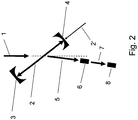
- a setup for generating a ⁇ beam by means of Compton back-scattering of laser light from an electron beam is shown schematically.
- An electron beam 1 is provided.
- laser pulses 2' are generated, which are provided at an angle relative to the direction of the electron beam 1.
- the laser pulse 2' is produced by standard means and injected in the space between two mirrors 3, 4, between which the laser pulse 2 is reflected repeatedly.
- a ⁇ beam 5 is generated by Compton back-scattering of the laser pulse 2 at the electron beam 1.
- Figure 2 shows a similar setup for producing radionuclides.
- the setup is similar to that of Fig. 1 , except that a second target 8 is positioned behind the target 6in propagation direction of ⁇ beam 5.
- the ⁇ beam 5 first hits the target 6.
- the ⁇ beam has high intensity and low beam spot size, some of the ⁇ quanta pass through the target 6 without inducing any nuclear reaction. Subsequently, these ⁇ quanta leave target 6 and form ⁇ beam 7 hitting the second target 8 and inducing nuclear reactions therein, such that the material comprised in the target 8 is converted.
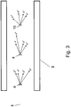
- Figure 3 shows another similar setup.
- three targets 6, 8, 10 are irradiated by the ⁇ beam 5.
- the targets 6, 8, 10 are aligned along the direction of the ⁇ beam.
- a number of reaction products like Compton electrons emerge upon irradiation. These products emerge at different angles with respect to the axis of ⁇ beam 5.
- the targets 6, 8, 10 are sufficiently spaced apart.
- the setup further comprises an envelope 9.
- the envelope 9 is used to cool the targets and to stop the reaction products emerging from the targets 6, 8, 10.
- the envelope may be water cooled.
- Figure 4a shows an apparatus for providing a ⁇ beam 5.
- the apparatus in figure 4a moreover, comprises means for monitoring and stabilizing the ⁇ beam 5.
- the apparatus comprises an electron source 10, an electron energy recovery linac (ERL) 11 and a beam dump 12. Electrons are generated by the electron source 10 and injected into the electron ERL 11. Here, the electrons are formed into an electron beam 1. The electron beam 1 passes one circulation before being dumped into the beam dump 12. The beam dump 12 is arranged behind the electron ERL 11.
- ERL electron energy recovery linac
- two stations for generating ⁇ beams are present. In other embodiments, more than two stations for generating ⁇ beams can be present, being aligned along the electron beam path.
- a laser pulse 2' is provided and is led via auxiliary mirrors 20, 20' into the space between two mirrors 3, 4.
- the mirrors 3, 4, 20, 20' are arranged to reflect the laser pulse 2 repeatedly.
- the laser pulse 2' enters the mirror setup via auxiliary mirror 20'.
- the laser pulse passes to auxiliary mirror 20, where it is reflected to mirror 3.
- the laser pulse 2 is reflected to mirror 4, where it is reflected back to auxiliary mirror 20'. Due to this closed-loop setup, the laser pulse 2 repeatedly passes the distance between mirrors 3 and 4.
- the electron beam 1 passes.
- the laser pulse 2 path and the electron beam 1 path cross at an angle of little less than 180°.
- the setup comprises a target 6 for producing the radionuclide B.
- a second station is provided in the apparatus of figure 4a .
- the second station comprises generating means for a second laser pulse 22', entering a mirror setup via auxiliary mirror 40'.
- the laser pulse then hits auxiliary mirror 40, where it is reflected to mirror 24.
- the laser pulse 22 is reflected to mirror 23, reflecting the laser pulse back to auxiliary mirror 40'.
- the mirrors 23, 24 and the auxiliary mirrors 40, 40' are arranged in a closed-loop configuration.
- the mirrors 23, 24 are arranged such that electron beam 1 passes the distance between the mirrors 23 and 24.
- a second high-intensity ⁇ beam 25 is generated.
- a dedicated second target 26 is arranged along the direction of the second ⁇ beam 25.
- the second target 26 is chosen as to release neutrons 27 upon radiation by the second ⁇ beam 25.
- the apparatus comprises a detector setup having a converter target 28 and a detector 29.
- the converter target 28 is a uranium converter target and the detector 29 comprises a pixeled scintillation detector.
- other types of converter targets and/or detectors may be used.
- the converter target 28 is placed immediately before the detector 29.
- the detector setup is arranged behind the second target 26 in the direction of the second ⁇ beam 25.
- the neutrons 27 being released from the dedicated second target 26 move towards the detector setup.
- the detector setup is arranged such as to measure the energy of the released neutrons 27 by time-of-flight. Adding the neutron binding energy of the second target 26 to the measured neutron 27 energy then provides an accurate online measurement of the second ⁇ beam 25 energy and energy spread. These, in turn, are indicative of the electron beam 1 energy and electron beam 1 energy spread. This, in turn, indicates the energy and energy spread of the ⁇ beam 5 used for radionuclide production.
- the apparatus of figure 4a moreover comprises a feedback signal lead 30.
- the measured results of the detector setup comprising the detector 29 are fed back to the electron ERL 11 such as to adjust electron beam parameters based on the measurement results.
- the electron beam 1 energy provided by the electron ERL 11 is controlled based on the feedback signal from the detector 29.
- the electron ERL 11 will increase the electron beam 1 energy.
- the electron ERL 11 will decrease the electron beam 1 energy. Adjusting the electron beam 1 energy also modifies the ⁇ beam energy. This way, the electron beam 1 may be stabilized, and, consequently also the ⁇ beam 5 may be stabilized.
- the neutron 27 energy spread can be detected by the detector setup comprising the detector 29.
- the measured neutron 27 energy spread is indicative of the second ⁇ beam 25 energy spread, which, in turn, indicates an electron beam 1 energy spread and, consequently, also the ⁇ beam 5 energy spread.
- the apparatus of figure 4a thus also allows to monitor and stabilize the ⁇ beam 5 energy spread.
- Figure 4b shows a setup which is similar to that of Figure 4a .
- the apparatus shown in Figure 4b furthermore comprises an additional assembly positioned behind the target 6 in the direction of the ⁇ beam 5.
- a crystal 50 is positioned behind the target 6, such that a portion of the ⁇ beam 5 passing through the target 6 hits the crystal 50.
- the ⁇ beam 5 is diffracted by the crystal 50 resulting in a diffracted ⁇ beam 52.
- the diffracted ⁇ beam 52 and the original ⁇ beam 5 enclose an angle denoted by 0.
- the apparatus shown in Figure 4b further comprises a collimator 54.
- the diffracted ⁇ beam 52 passes through the collimator 54 and hits a second crystal 51.
- the second crystal 51 is positioned behind the collimator 54 in the direction of the diffracted ⁇ beam 52. Hitting the second crystal 51, the diffracted ⁇ beam 52 is diffracted again.
- the apparatus further comprises a position sensitive detector 53 which is placed behind the second crystal 51.
- the apparatus shown in Figure 4b allows for an additional monitoring of the ⁇ beam.
- a portion of the ⁇ beam 5 used for production of the target isotope is directly used for monitoring purposes.
- the position sensitive detector is coupled to the energy recovery linac via an additional feed back signal lead for improved controlling of the electron beam.
- a refractive ⁇ -lens may be employed for focussing the ⁇ -beam onto the target 6, thereby further increasing the ⁇ -flux in the target region.
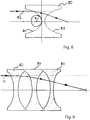
- FIG 8 a schematic view of a single refractive ⁇ -lens 80 is shown.
- a refractive focusing lens has a convex profile, since the index of refraction is larger than unity.
- the index of refraction is actually slightly smaller than unity, such that a focusing refractive ⁇ -lens will have a concave shape.
- a single lens has two parabolic surfaces 81 to avoid spherical aberrations. The incident gamma ray 82 is refracted when passing through the surfaces of parabolas.
- FIG 9 a stack of three single refractive lenses 80 is shown. Since the index of refraction of gamma rays in matter is very close to unity, a large number, typically 1,000 to 5,000 of single lenses are required to increase the total refraction power.
- the refraction of each (single) lens increases as the radius of curvature R (as shown in Figure 8 ) decreases.
- Refractive ⁇ -lenses may generally be made from different materials, such as beryllium, aluminium, nickel, silicon or diamond.
- a preferred way of fabricating arrays of refractive ⁇ -lenses is to use silicon and employ highly developed industrial nano-structuring techniques that are available in the art.
- This method has, in particular, advantages over (ion, xn + yp) reactions, where the "ion” could be p, d or ⁇ particles from particle accelerators like cyclotrons and (n, ⁇ ) or (n,f) reactions from nuclear reactors.
- the energy deposition in the target can be managed by using a stack of thin target foils or target wires, hence avoiding direct stopping of the Compton and pair electrons/positrons.
- ions with a strong atomic stopping only a fraction of less than 10 -2 leads to nuclear reactions resulting in a target heating, which is at least 10 5 times larger and often limits the achievable specific activity.
- the well de-fmed initial excitation energy of the compound nucleus leads to a small number of reaction channels with new combinations of target isotope and final radioisotope.
- the narrow bandwidth ⁇ excitation may make use of the fine structure of the Pygmy Dipole Resonance (PDR) or fluctuations in ⁇ -width leading to increased cross sections.
- PDR Pygmy Dipole Resonance
- a target area on the order of 100 ⁇ m 2 can be highly transmuted, resulting in a very high specific activity.
- ( ⁇ , ⁇ ') isomer production via specially selected ⁇ cascades allows to produce high specific activity in multiple excitations, where no back-pumping of the isomer to the ground state occurs.
- Photonuclear reactions may allow to produce certain radioisotopes with higher specific activity more economically.
- radioisotopes are used for both diagnostic and therapeutic purposes.
- Many diagnostics applications are based on molecular imaging methods, i.e. either on positron emitters for 3D imaging with PET (positron emission tomography) or gamma ray emitters for 2D imaging with planar gamma cameras or 3D imaging with SPECT (single photon emission computer tomography).
- the main advantage of nuclear medicine methods is the high sensitivity of the detection systems that allows using tracers at extremely low concentrations (some pmol in total, injected in typical concentrations of nmol/l). This extremely low amount of radiotracers assures that they do not show any (bio-)chemical effect on the organism.
- the diagnostic procedure does not interfere with the normal body functions and provides direct information on the normal body function which is not perturbed by the detection method.
- even elements that would be chemically toxic in much higher concentrations can be safely used as radiotracers (e.g. thallium, arsenic, etc.).
- radiotracers of high specific activity i.e. that the injected radiotracer is not accompanied by too much stable isotopes of the same (or a chemically similar) element.
- the present invention is particularly useful, as the radionuclide B can be produced with high specific acitivity.
- Radioisotopes are also used for therapeutic applications, in particular for endo-radiotherapy.
- Targeted systemic therapies allow fighting diseases that are non-localized, e.g. leukaemia and other cancer types in an advanced state when already multiple metastases have been created.
- a bioconjugate is used that shows a high affinity and selectivity to bind to cancer cells.
- a suitable radioisotope such as a (low-energy) electron or alpha emitter allows to selectively irradiate and destroy the cancer cells.
- these therapies are called Peptide Receptor Radio Therapy (PRRT) when peptides are used as bioconjugates or radioimmunotherapy (RIT) when antibodies are used as bioconjugates.
- PRRT Peptide Receptor Radio Therapy
- RIT radioimmunotherapy
- Bioconjugates could also be antibody-fragments, nanoparticles, microparticles, etc.
- an increase of the concentration of the bioconjugates may lead to blocking of these sites and, hence, to a reduction in selectivity. Therefore the radioisotopes for labelling of the bioconjugates should have a high specific activity to minimize injection of bioconjugates labelled with stable isotopes that do not show radiotherapeutic efficiency. Thus often high specific activities are required for radioisotopes used in such therapies.
- the tumor uptake of bioconjugates varies considerably from one patient to another. This leads to an important variation in dose delivered to the tumour if the same activity (or activity per body mass or activity per body surface) was administered.
- a personalized dosimetry should be performed by first injecting a small quantity of the bioconjugate in question, marked by an imaging isotope (preferentially ⁇ + emitter for PET).
- an imaging isotope preferentially ⁇ + emitter for PET.
- the tumor uptake can be quantitatively determined and the injected activity of the therapy isotope can be adapted accordingly.
- the PET tracer should be ideally an isotope of the same element as the therapy isotope, or, at least of a chemically very similar element such as neighbouring lanthanides.
- matched pairs of diagnostic and therapy isotopes are of particular interest: 44(m) Sc/ 47 Sc, 61 Cu or 64 Cu/ 67 Cu, 86 Y/ 90 Y, 123 I or 124 I/ 131 I or 152 Tb/ 149 Tb or 161 Tb. Often the production of one of these isotopes is less straightforward with classical methods. Therefore "matched pairs" are not yet established as standard in clinical practice. The present invention allows for widespread implementation of this method.
- Neutron capture (n, ⁇ ) reactions transmute a stable isotope into a radioactive isotope of the same element. High specific activities are obtained if the (n, ⁇ ) cross section is high and the target is irradiated in a high neutron flux.
- Neutrons most useful for (n, ⁇ ) reactions have energies from meV to keV (thermal and epithermal neutrons) and are provided in the irradiation positions of high flux reactors at flux densities of several 10 14 n/(cm 2 s), up to few 10 15 n/(cm 2 s). If the neutron capture cross section is sufficiently high, then a good fraction of the target atoms can be transmuted to the desired product isotopes, resulting in a product of high specific activity.
- High specific activities can also be achieved by using indirect production paths.
- the (n, ⁇ ) reaction is not populating directly the final product but a precursor that decays by beta decay to the final product.
- the final product differs in its chemical properties from the target and can be chemically separated from the bulk of the remaining target material.
- Fission is another process used for isotope production in nuclear reactors. Radiochemical separation leads to radioisotopes of "non-carrier-added" quality, with specific activity close to the theoretical maximum.
- Imaging for diagnostic purposes requires either ⁇ + emitters for PET, or isotopes emitting gamma-rays with suitable energy for SPECT (about 70 to 300 keV), if possible without ⁇ (+/-) emission to minimize the dose to the patient.
- electron capture decay is preferred for such applications.
- these neutron-deficient isotopes cannot be produced by neutron capture on a stable isotope, 64 Cu being an exception. Instead they are mainly produced by charged-particle induced reactions such as (p,n), (p,2n), ...etc.
- High specific activities of the final product are achievable when the product differs in chemical properties from the target (i.e. different Z) and can be chemically separated from the remaining bulk of target material.
- Z must be changed in the nuclear reaction, e.g. in (p,xn), (p,2n), (p, ⁇ ) reactions.
- the energies of the charged particle beams for such reactions are usually in the range of 10 to 30 MeV and can be supplied with high currents (0.1 to 1 mA) by small cyclotrons.
- Another important technique is the use of generators, where short-lived radionuclides are extracted "on-tap" from longer-lived mother nuclides.
- the primary product isotope that was produced in the nuclear reaction
- the final radioisotope that is populated by decay of the primary product isotope and is used in the medical application.
- the generator is loaded with the primary product isotope, then the final radioisotope can be repetitively eluted and used.
- distillation or phase partitioning are used for the extraction of the shorter-lived isotope chromatographic techniques.
- generators are generally loaded with material of a given minimum specific activity.
- the present invention is, in particular, useful for producing the generator nuclide.
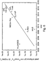
- Fig. 5 and Fig. 6 show the rapid progress of ⁇ beam properties for the bandwidth ( Fig. 5 ) and the peak brilliance ( Fig. 6 ) with time, starting with the Bremsstrahlung spectrum of the Stuttgart Dynamitron, which still had a very large bandwidth.
- the energy Eg decreases with ⁇ ⁇ .
- a small bandwidth of the ⁇ beam requires a small energy spread of the electron bunches ⁇ e / ⁇ e , a small bandwidth of the laser energy ⁇ E L / E L , a very good emittance of the electron beam with a small opening angle and small opening angle of the laser beam.
- the MEGa-Ray ⁇ beam runs with a macro pulse structure of 120 Hz using 1.5 J, 2 ps laser pulses, which are recirculated 100 times with 2 ns bunch spacing in a ring-down cavity.
- the group plans for lower energy ⁇ rays in the range of a only few MeV, too small for photonuclear reactions.
- a similar ⁇ facility is planned for the ELI-Nuclear Physics project (ELI-NP) in Romania, also based on a "warm” linac like the one used at MEGa-Ray, however designed for ⁇ energies up to 19 MeV, thus reaching interesting intensities and ⁇ energies for isotope production.
- ELI-NP ELI-Nuclear Physics project
- Hajima and co-workers at Ibaraki are developing a Compton back-scattering ⁇ beam using an energy recovery linac (ERL) and superconducting "cold" cavities.
- ERP energy recovery linac
- For smaller electron bunch charges very low normalized emittances of 0.1 mm mrad can be obtained from the electron gun.
- a high finesse enhancement cavity is used for recirculating the photons.
- the quality of the electron beam from the ERL can be preserved by running with higher repetition rate. Switching from a 1 mA electron current to a 100 mA current the peak brilliance and bandwidth can be improved significantly. Intensities of 5x10 15 ⁇ /s are expected.
- laser-accelerated electron bunches have been proposed as relativistic mirrors for Compton back-scattering and the production of intense ⁇ beams and can be used in conjunction with the present invention.
- the yield of resonant photonuclear reactions which are discussed below depends strongly on the exact energy and the band width of the ⁇ beam. Both parameters are determined by the quality of the laser beam and of the electron beam.
- the laser beam parameters are usually well controlled by means that are conventionally used in laser spectroscopy. More importantly, the electron beam parameters need to be tuned and monitored with high precision.
- the ⁇ beam energy needs to be measured with a system that has a far better energy resolution than the ⁇ beam itself. It is, however, not trivial to measure a high energy ⁇ beam energy with such a high precision.
- conventional Ge detectors are limited to an energy resolution in the order of 10 -3 . Scintillation detectors, on the other hand, have an even worse energy resolution.
- two methods are particularly preferred:
- a thin single or mosaic crystal i.e. SiGe, SiO 2 , CO, graphite, etc.
- the crystal may be placed in front, inside or behind the production target.
- a small portion of the ⁇ beam will be diffracted by the crystal according to the Bragg condition.
- Placing a beam detection system at a large distance from the crystal allows measuring the diffraction angle either by scanning the beam through narrow collimators by turning the crystal or by using a fixed crystal and a detector with a high spatial resolution.
- the wavelength of the beam can be deduced which directly gives the beam energy.
- the angular spread of the diffracted beam is, moreover, a measure of the energy spread of the electron beam.
- the deduced energy and energy spread can be used for a feedback system for tuning and monitoring the electron beam used for the ⁇ beam production. Due to the high intensity of the ⁇ beam, even with thin crystals and in high reflection order, enough photons will arrive at the detector. A higher reflection order is preferred, since it allows placing the detector further away from the original, non-diffracted beam. For ⁇ beams having a larger opening angle, the latter would, however, limit the achievable energy resolution.
- An additional collimator 54 is placed between both crystals 50, 51 to eliminate ⁇ beams of other diffraction orders.
- a collimator is additionally or alternatively placed between the second crystal and the detector. Using two consecutive diffractions in the same direction will add to the energy dispersion and provide a very high energy resolution. Two diffractions in opposite directions, on the other hand, allow measuring the intrinsic resolution of the measurement system.
- the rotation angle of the crystals is usually controlled by laser interferometers.
- Such a double crystal spectrometer enables measuring ⁇ beam energies with a resolution below 10 -6 and hence fully complies with the needs to stabilize the ⁇ beam within the desired band width. More details on the layout, operation and performance of a suitable crystal spectrometer were described by M. S. Dewey et al., Phys. Ref. C 73 (2006), 044303 and references therein.
- a second ⁇ beam from a second ⁇ beam production station can be used for monitoring the electron beam energy.
- the second ⁇ beam may have a different wave length.
- the second ⁇ beam is sent to a dedicated target where it induces ( ⁇ ,n) reactions just above the threshold. Neutrons are released within the eV to keV range. Due to the pulsed nature of the ⁇ beam, the neutron energy can be measured by time of flight with a good precision of a few eV or better. Adding the neutron energy to the well known neutron binding energy of the target then provides an accurate online measurement of the ⁇ beam energy and the ⁇ beam energy spread. These are also indicative of the electron beam energy and the electron beam energy spread. Again, this information is used for a feedback system to optimize and stabilize the electron accelerator parameters.
- Neutron detection can be realized in various ways.
- a "neutron converter” combined with a charged particle detector.
- neutron converter different materials containing isotopes like e.g. 6 Li, 10 B or 235 U may be used.
- the 10 B(n, ⁇ ) 6 Li reaction has a flat cross section which is about 6 barn at 10 keV, rising towards lower energies.
- Even boron loaded plastic scintillators like, e.g. BC-454 from Saint Gobain can be used.
- 235 U is a good converter for neutrons of a few keV with a cross section of about 5 barn. Below 1 keV, there are stronger variations of the resonance cross sections of 235 U(n,f).
- the converter layer is preferably less than 50 ⁇ m thick.
- the lengths of the neutron flight paths should be adjusted to the neutron energies, and may be several meters long.
- Radioisotopes for medical applications have typically half-lives of hours to days, hence the flux density ⁇ (in part./(cm 2 s)) should approach or exceed a value of about 10 19 / ⁇ (in barn) where ⁇ is the cross-section.
- the flux density can reach several 10 19 ⁇ /(cm 2 s), i.e. the target can be efficiently transmuted by photonuclear reactions with cross sections of a few 100 mb.
- g is a spin factor close to unity.
- a probability of ⁇ >/D ⁇ 1% a resonance is hit.
- Gamma rays deposit their energy in quantized interactions with matter, such as Compton scattering, pair creation, photo effect or photonuclear reactions.
- matter such as Compton scattering, pair creation, photo effect or photonuclear reactions.
- a typical total cross section of 10 b/atom and a target thickness of 10 6 atomic layers about 5% of the ⁇ quanta will suffer an energy loss by Compton scattering of 100 keV and about 5% will undergo pair creation at 10 MeV.
- thin targets of less than 0.1 g/cm 2 less than 10 -2 of the electrons are stopped and less than 5*10 -5 of the energy is deposited. Electrons are scattered very fast
- the typical intensity of proton beams used for isotope production is of the order of 100 ⁇ A/cm 2 , corresponding to 6x10 12 /(mm 2 s).
- the target should withstand a ⁇ flux density of 10 15 /[(0.1mm) 2 s].
- the usable target thickness ranges from 20 g/cm 2 for heavy elements to 40 g/cm 2 for light elements, e.g. only few mg target material are exposed to the small area of the ⁇ beam. With non-resonant reactions, activities on the order of 0.1 TBq can be produced per day, corresponding to tens (for ⁇ - therapy isotopes) up to thousands (for imaging isotopes and therapy with ⁇ emitters such as 225 Ac) of patient doses.
- the target elements may be used in the form of metals, oxides, carbides or other compounds, e.g. with light elements. Light elements have a relatively low cross section for gamma rays, hence the specific activity achieved with compound targets is not much lower compared to elemental targets.
- the exact target geometry does not affect our estimates.
- a single compact target or a stack of thin target foils may be used. This would provide similar production rates. In practice the latter solution can stand far higher beam intensities.
- the foils may be radiation-cooled in vacuum or helium-cooled since helium has a low Z and correspondingly low cross section for interaction with gamma rays. Due to the low divergence of the ⁇ beam, the individual target foils can be spaced wide apart, thus reducing the view factors between the foils to minimize mutual heating by radiation absorption. For sufficiently thin foils most of the forward-directed Compton and pair electrons and positrons can leave the foil.
- Spacing the foils further apart reduces the energy deposition from electrons of the previous foil which deposit their energy laterally (e.g. in a water-cooled target chamber) spread over a wide area.
- the trajectories of the electrons and positrons may further be forced outward by applying a transversal magnetic field.
- a stack of target foils with thin water-cooling channels in between can be considered since hydrogen and oxygen have much lower interaction cross sections with gamma rays.
- a thin wire or several consecutive wires may be placed along the ⁇ beam direction.
- the wires may have a diameter on the order of e.g. 0.1 mm.
- most electrons and positrons that are emitted under angles different from 0° will rapidly leave the target and will not contribute much to its heating. Even those that are initially emitted in a forward direction will rapidly change direction by scattering and then leave the wire.
- a solution maybe realized more simply than a multi-foil stack.
- the target material may also be present in liquid form, e.g. in form of an aqueous solution, if the flux density of the ⁇ beam is not too high. Even for a ⁇ beam facility that provides a ⁇ beam with high initial flux density and with several targets placed in a row, the flux density will be decreased. In order to make use of the ⁇ beam with decreased intensity, the material of the downstream targets may be provided in aqueous form.
- the target stack may also consist of different targets for simultaneous production of different isotopes. This is possible when the different reactions require similar ⁇ energies. It may be particularly efficient when at least one of the reactions is characterized by prominent resonances reducing the interaction length for resonant ⁇ rays. The "unused" ⁇ rays within the bandwidth of the ⁇ beam may then be used downstream for other reactions that are not resonant or have resonances at different energies.
- 117m Sn Also 117m Sn emits low energy conversion and Auger electrons, making it promising for radionuclide therapy. In addition it emits a 159 keV gamma ray for imaging.
- 117m Sn can be used for pain palliation in bone metastases of various cancers. Due to its soft electron energy spectrum it has less side effects on the bone marrow than other radioisotopes with more penetrating radiation. Unfortunately the high-spin isomer 117m Sn is poorly produced in thermal neutron capture on zero-spin 116 Sn.
- Enriched 187 Re targets may be used to minimize contamination of the product with long-lived 184,184m Re by 185 Re( ⁇ ,n) reactions.
- Slightly neutron-deficient isotopes are decaying by electron capture with emission of X-rays and low-energy Auger electrons, partially also gamma rays and conversion electrons.
- the absence of beta emission and the presence of low-energy X-rays or electrons is of advantage for a variety of applications such as calibration sources, radionuclide therapy applications after internalization into cells, etc. All these isotopes can be produced by neutron capture on the stable (A-1) neighboring isotope. However, the latter is usually very rare in nature (since only produced by unusual astrophysical processes like the p-process) and correspondingly costly when produced as isotopically enriched target material.
- ( ⁇ ,n) reactions to populate the same isotopes allows using the much more abundant, and hence cheaper, (A+1) neighboring isotope as target.
- An example is 103 Pd, a low-energy electron emitter. It can be used for targeted radiotherapy (coupled to a suitable bioconjugate) or for brachytherapy applications where sources ("seeds") are inserted into a cancer (e.g. breast cancer) for localized irradiation.
- the target 102 Pd for production by neutron capture is rare and expensive. Production via 104 Pd( ⁇ ,n) is more economic, if sufficiently intense gamma beams are available.
- Photo-fission of uranium or thorium targets allows production of 99 Mo and other isotopes with highest specific activity.
- the here proposed ⁇ -beams with high flux density are not suitable since they lead to an excessive target heating.
- Radioisotopes directly, i.e. not necessarily coupled to a bio-molecule.
- micro- or nanoparticles that are doped with radioisotopes. They can be used for intratumoral injection, e.g. to treat liver metastases. When injected locally, macrophages will detect these particles and absorb them. These macrophages have then a high probability to "get stuck" in parts of the liver that are obstructed by tumor metastases.
- the radioisotopes contained in the micro- or nanoparticles can then irradiate these metastases with their medium-range radiation (beta particles or low-energy X-rays or gamma rays).
- the radioisotopes can be introduced into the micro- or nanoparticles in various ways:
- Radioisotopes can also be bound in larger solid matrices that are then mechanically (surgically) introduced into the body or brought close to it to irradiate tumors or benign diseases.
- brachytherapy is today routinely used to treat prostate cancer by permanently introduced seeds containing radioactive 125 I. It is also useful to prevent in-stent restenosis by intravascular brachytherapy using radioactive stents, to prevent closure of the pressure relief channel in glaucoma filtering surgery by radioactive implants or to perform other antiinflammatory or anti-proliferative treatments. Photonuclear reactions could simplify the production of the respective stents or seeds.
- radioactive targets are more efficiently converted into the required product isotopes, hence more compact and less active targets can be employed, resulting in less activity to be handled and less dose rate.
- a further advantage of using the low bandwidth ⁇ beams is that the higher cross-section for monochromatic beams leads to a short interaction length (cm or less). This leads to an additional reduction of the required target mass. This reduces further the target costs and increases correspondingly the specific activity.
- Isotopic enrichment may not necessarily be needed, when for a given gamma energy the wanted cross section is much higher than for other isotopes.
- PDR Pygmy dipole resonance
- GDR giant dipole resonance
- a further optional increase of the specific activity is possible by one or more of the following:
- ⁇ beam facilities Using the new ⁇ beam facilities one can use compact targets, which are exposed to the gamma radiation and undergo photonuclear reactions such as ( ⁇ , ⁇ '), ( ⁇ ,n), ( ⁇ ,p), ( ⁇ ,2n) to form radioisotopes. After a suitable irradiation time, a radioisotope with high specific activity is produced. After the usual radiochemical and radiopharmaceutical steps (such as optionally dissolving of the target, optionally chemical purification, optionally labelling, quality control, ..) a radiopharmaceutical product is created for use in diagnostic or therapeutic nuclear medicine procedures. The produced radioisotope may be used directly for nuclear medicine applications.
- the investment and running costs of the proposed ⁇ - beam facility are on the order of 40 MEUR and few MEUR/year. This is cheaper than a high flux reactor, but more expensive than compact cyclotrons that provide charged particles with 10 to 20 MeV suitable for production of PET tracers. World-wide more than 600 such cyclotrons exist, often based at hospitals or close-by. They provide regularly the short-lived PET isotopes 18 F, 11 C, 13 N and 15 O for molecular imaging applications. Although it would be possible to produce also such isotopes by photonuclear reactions (e.g. 20 Ne( ⁇ ,np) 18 F), a more complex Compton backscattering facility would be an overkill for such applications.
- photonuclear reactions e.g. 20 Ne( ⁇ ,np) 18 F
- the main advantage of the gamma beam facility is the new and rather unique access to radioisotopes or isomers with high specific activity that can complement and extend the choice of radioisotopes for nuclear medicine applications.
Landscapes
- Chemical & Material Sciences (AREA)
- Chemical Kinetics & Catalysis (AREA)
- General Chemical & Material Sciences (AREA)
- Physics & Mathematics (AREA)
- Engineering & Computer Science (AREA)
- General Engineering & Computer Science (AREA)
- High Energy & Nuclear Physics (AREA)
- Particle Accelerators (AREA)
- Medicines Containing Antibodies Or Antigens For Use As Internal Diagnostic Agents (AREA)
Claims (14)
- Verfahren zum Herstellen eines Radionuklidprodukts B, das die folgenden Schritte umfasst:Bereitstellen eines Targets (6), welches eine Menge eines Nuklids A enthält,Bereitstellen eines γ-Strahls (5) durch Compton-Rückstreuung von Laserlicht (2) an einem Elektronenstrahl (1),Bestrahlen des Targets (6) mit dem γ-Strahl (5), um dadurch zumindest einen Teil der Menge des Nuklids A in das Produkt B umzuwandeln, dadurch gekennzeichnet, dass das Bereitstellen des Targets (6) das Auswählen eines Nuklids A derart umfasst, dass A durch eine (γ, γ')-Reaktion oder eine (γ, n)-Reaktion in das Produkt B urnwandelbar ist,und dass das Bereitstellen des γ-Strahls das Bereitstellen eines γ-Strahls mit einer Photonenenergie zwischen 0,5 und 10 MeV im Falle einer (γ, γ')-Reaktion und zwischen 5 und 20 MeV im Falle einer (γ, n)-Reaktion umfasst, wobei das Bereitstellen des γ-Strahls (5) das Bereitstellen des γ-Strahls mit einer Energie-Bandbreite ΔE/E FWHM zwischen 10-2 und 10-12 umfasst.
- Verfahren nach Anspruch 1, bei dem das Bereitstellen des γ-Strahls (5) das Bereitstellen des γ-Strahls mit einer einstellbaren Photonenenergie umfasst, und das Einstellen der Photonenenergie entsprechend dem Produkt B und dem ausgewählten Nuklid A umfasst.
- Verfahren nach einem der vorhergehenden Ansprüche, bei dem das Bereitstellen des γ-Strahls (5) das Bereitstellen des Elektronenstrahls (1) durch einen Linearbeschleuniger, vorzugsweise durch einen Energierückgewinnungslinearbeschleuniger (energy recovery LINAC, ERL) oder einen warmen Linearbeschleuniger umfasst, oder durch das Bereitstellen eines laser-angetriebenen Elektronenstrahls umfasst.
- Verfahren nach einem der vorhergehenden Ansprüche, bei dem das Target (6) das Nuklid A in angereicherter Form oder in natürlichem Vorkommen enthält.
- Verfahren nach einem der vorhergehenden Ansprüche, bei dem das Bereitstellen des γ-Strahls (5) das Bereitstellen des γ-Strahls (5) mit einer Flussdichte am Target zwischen 1010 und 1021 γ/(s cm2) insbesondere zwischen 1011 und 1020 γ/(s cm2) und vorzugsweise zwischen 1013 und 1019 γ/(s cm2) umfasst, und/oder bei dem das Bereitstellen des γ-Strahls (5) das Bereitstellen des γ-Strahls (5) mit einem Öffnungswinkel von weniger als 10 mrad, insbesondere weniger als 1 mrad, und vorzugsweise weniger als 200 µrad umfasst, und/oder
bei dem das Bereitstellen des γ-Strahls (5) das Bereitstellen des γ-Strahls (5) mit einer Intensität von mehr als 1010 Photonen/s, insbesondere zwischen 1011 und 1020 Photonen/s, vorzugsweise zwischen 1011 und 1017 Photonen/s, und am meisten bevorzugt zwischen 1013 und 1016 Photonen/s umfasst. - Verfahren nach einem der vorhergehenden Ansprüche, bei dem das Bereitstellen des γ-Strahls (5) das Bereitstellen des γ-Strahls (5) mit einer Energiebandbreite ΔE/E FWHM zwischen 10-2 und 10-10, vorzugsweise zwischen 10-3 und 10-8, noch bevorzugter zwischen 10-3 und 10-7 und am meisten bevorzugt zwischen 10-4 und 10-7 umfasst, und/oder
bei dem das Bereitstellen des γ-Strahls (5) das Bereitstellen des γ-Strahls (5) mit einem Querschnitt am Target zwischen 1 µm2 und 10 mm2, insbesondere zwischen 100 µm2 und 1 mm2, und vorzugsweise zwischen 1.000 µm2 und 50.000 µm2 umfasst. - Verfahren nach einem der vorhergehenden Ansprüche, umfassend das Auswählen des Nuklids A in Abhängigkeit von dem erwünschten Radionuklidprodukt B aus der folgenden Liste von Kombinationen von Nuklid A, Kernreaktion und Radionuklid B:195Pt(γ,γ')195mPt, 226Ra(γ,n)225Ra, 48Ca(γ, n)47Ca, 104Pd(γ,n)103Pd, 65Cu(γ,n)64Cu, 166Er(γ,n)165Er, 170Er(γ,n)169Er, 48Ti(γ,p)47Sc, 187Re(γ,n)186Re, 117Sn(γ,γ')117mSn, 87Sr(γ,γ')87mSr, 115In(γ,γ')115mIn, 119Sn(γ,γ')119mSn, 123Te(γ,γ')123mTe, 125Te(γ,γ')125mTe, 129Xe(γ,γ')129mXe, 131Xe(γ,γ')131mXe, 135Ba(γ,y')135mBa, 176Lu(γ,γ')176mLu, 180Hf(γ,γ')180mHf, 193Ir(γ,γ')193mIr, 52Cr(γ,n)51Cr, 56Fe(γ,n)55Fe, 72Ge(γ,n)71Ge, 76Se(γ,n)75Se, 86Sr(γ,n)85Sr, 98Ru(γ,n)97Ru, 108Cd(γ,n)107Cd, 110Cd(γ,n)109Cd, 114Sn(γ,n)113Sn, 122Te(γ,n)121Te, 122Te(γ,n)121mTe, 128Xe(γ,n)127Xe, 134Ba(γ,n)133Ba, 134Ba(γ,n)133mBa, 140Ce(γ,n)139Ce, 154Gd(γ,n)153Gd, 160Dy(γ,n)159Dy, 170Yb(γ,n)169Yb, 176Hf(γ,n)175Hf, 182W(γ,n)181W, 192Pt(γ,n)191Pt, 194Pt(γ,n)193mPt.
- Verfahren nach einem der vorhergehenden Ansprüche, bei dem der Schritt des Bereitstellens des γ-Strahls (5) ferner das Stabilisieren des γ-Strahls (5) umfasst;
wobei das Stabilisieren des γ-Strahls (5) das Überwachen der Energie des γ-Strahls (5) und/oder der Energiebandbreite des γ-Strahls (5) und das Einstellen des Elektronenstrahls (1) in Übereinstimmung mit einem Resultat der Überwachung umfasst;
wobei der Schritt des Überwachens vorzugsweise folgendes umfasst:Aussenden eines zweiten γ-Strahls von einer γ-Strahl-Erzeugungsstation,welche sich zumindest teilweise in dem Elektronenstrahl (1) befindet, zu einem zugehörigen zweiten Target, wodurch Neutronen aus dem zugehörigen zweiten Target freigesetzt werden, und Messen der Energie der freigesetzten Neutronen, insbesondere durch Flugzeitmessung, und/oderwobei der Schritt des Überwachens das Messen eines Bragg-Winkels eines Teils des γ-Strahls (5) umfasst, welcher an einem in dem γ-Strahl (5) vorgesehenen Kristall Bragggebeugt wird. - Verfahren nach einem der vorhergehenden Ansprüche, bei dem das Verfahren ferner mindestens einen Schritt umfasst, in dem eine Menge des Radionuklids B mit einem Molekül gekoppelt wird, um ein Biokonjugat zu bilden, und/oder wobei das Verfahren ferner das Speichern des bestrahlten Targets für eine Zeitdauer umfasst, die es dem Radionukleidprodukt B gestattet, in ein Radionuklid-Endprodukt C zu zerfallen, wobei A, B, C vorzugsweise ausgewählt sind aus einer Gruppe bestehend aus 226Ra, 225Ra, 225Ac und 48Ca, 47Ca, 47Sc, und
wobei die Zeitdauer insbesondere zwischen 0,01- und 20-mal der Halbwertszeit T1/2 des Radionuklidprodukts B entspricht, vorzugsweise zwischen 0,05- und 10-mal der Halbwertszeit T1/2 und am meisten bevorzugt zwischen 0,1- und 3-mal der Halbwertszeit T1/2 beträgt, und/oder
wobei das Verfahren vorzugsweise ferner das chemische Trennen des Radionukleidprodukts B oder des Radionukleidendprodukts C von dem Target umfasst, wobei, noch bevorzugter, der Schritt des Trennens wiederholt wird. - Verfahren nach einem der vorhergehenden Ansprüche, bei dem das Verfahren ferner die folgenden Schritte umfasst:Bereitstellen von n Targets (6, 8, 10), von denen ein jedes eine Menge eines jeweiligen Nukleids Ai umfasst, wobei die Nukleide Ai identisch oder verschieden sein können, Positionieren der n Targets (6, 8, 10) in einer Reihe hintereinander entlang der Richtung des γ-Strahls (5),Bestrahlen der Targets (6, 8, 10), wodurch zumindest ein Teil der Menge eines jeden Nuklids Ai in das zugehörige Radionukleidprodukt Bi umgewandelt wird, wobei i eine Zahl zwischen 1 und n ist, wobei n vorzugsweise zwischen 2 und 1.000, vorzugsweise zwischen 10 und 100 liegt, und/oderwobei eines oder mehrere der n Targets (6, 8, 10) ein Folientarget oder ein Target aus dünnen Drähten umfasst, und/oderwobei eines oder mehrere der n Targets (6, 8, 10) in flüssiger Form vorliegt, vorzugsweise in wässriger Lösung.
- Verfahren nach einem der vorhergehenden Ansprüche, bei dem das Target (6) ein implantierbares Produkt umfasst, wobei das implantierbare Produkt vorzugsweise einen Stent, einen Seed, ein biodegradierbares Implantat, Mikro- oder Nanopartikel umfasst, und wobei das implantierbare Produkt am meisten bevorzugt geeignet ist für Brachytherapie oder Radioembolisierungsanwendungen.
- Vorrichtung, die geeignet ist, ein Radionuklidprodukt B nach einem Verfahren nach einem der Ansprüche 1 bis 11 herzustellen, umfassend:einen Elektronenbeschleuniger zum Bereitstellen des Elektronenstrahls (1),eine Laserlichtquelle zum Bereitstellen des Laserlichts (2),Mittel zum Durchführen der Compton-Rückstreuung des Laserlichts (2) von dem Elektronenstrahl (1) zum Erzeugen des γ-Strahls (5),Mittel zum Halten oder Aufnehmen des Targets (6), sodass das Target, wenn es gehalten oder aufgenommen ist, zumindest teilweise in dem γ-Strahl angeordnet ist.
- Vorrichtung nach Anspruch 12, bei der der Elektronenbeschleuniger geeignet ist, den Elektronenstrahl (1) mit zumindest einem einstellbaren Parameter bereitzustellen, wobei der mindestens eine Parameter vorzugsweise eine Elektronenstrahlenergie und/oder eine Elektronenstrahlenergiebandbreite umfasst und/oder
wobei die Vorrichtung ferner ein System zum Überwachen des γ-Strahls (5) umfasst,wobei das System vorzugsweise folgendes umfasst:eine γ-Strahl-Erzeugungsstation, die zumindest teilweise in dem Elektronenstrahl (1) angeordnet und ferner geeignet ist, einen zweiten γ-Strahl zu erzeugen,ein zweites Target, welches geeignet ist, in Antwort auf eine Bestrahlung mit dem zweiten γ-Strahl Neutronen freizusetzen, undMittel zum Messen der Energie der Neutronen, die aus dem zweiten Target freigesetzt wurden, und/oderwobei die Vorrichtung ferner mindestens eine zusätzliche Laserlichtquelle zum Bereitstellen mindestens eines weiteren Laserlichtstrahls umfasst,zusätzliche Mittel zum Durchführen der Compton-Rückstreuung des mindestens einen zusätzlichen Laserlichtstrahls an dem Elektronenstrahl, zum Erzeugen mindestens eines zusätzlichen γ-Strahls, undzusätzliche Mittel zum Halten oder Aufnehmen mindestens eines zusätzlichen Targets, sodass jedes des mindestens einen zusätzlichen Targets, wenn es gehalten oder aufgenommen ist, zumindest teilweise innerhalb des mindestens einen zusätzlichen Strahls angeordnet ist,wobei der Laserlichtstrahl und der mindestens eine zusätzliche Laserlichtstrahl vorzugsweise unterschiedliche Wellenlängen haben. - Vorrichtung nach Anspruch 12 oder 13, die ferner eine Bestrahlungskammer umfasst, wobei die Bestrahlungskammer Mittel zum Halten oder Aufnehmen von zwei oder mehr Targets (6, 8, 10) aufweist, die entlang der Richtung des γ-Strahls (5) ausgerichtet sind, und/oder
wobei die Bestrahlungskammer geeignet ist, das eine oder die mehreren Targets aufzunehmen und ein Vakuum, ein Gas, vorzugsweise Helium, oder eine Flüssigkeit, vorzugsweise Wasser zu enthalten, und wobei die Bestrahlungskammer vorzugsweise Einlassmittel und Auslassmittel für ein Gas oder eine Flüssigkeit umfasst, und noch bevorzugter Mittel zum Erzeugen eines Gasflusses oder Flüssigkeitsflusses in der Bestrahlungskammer umfasst,
und/oder wobei die Bestrahlungskammer mindestens eines des einen oder der mehreren Targets in flüssiger Form, vorzugsweise in wässriger Lösung enthält.
Priority Applications (1)
| Application Number | Priority Date | Filing Date | Title |
|---|---|---|---|
| EP11760997.4A EP2606489B1 (de) | 2010-08-20 | 2011-08-19 | Verfahren zur herstellung von isotopen, insbesondere verfahren zur herstellung von radioisotopen mittels bestrahlung mit gammastrahlen |
Applications Claiming Priority (4)
| Application Number | Priority Date | Filing Date | Title |
|---|---|---|---|
| EP10008708 | 2010-08-20 | ||
| EP10186576A EP2421006A1 (de) | 2010-08-20 | 2010-10-05 | Verfahren zur Herstellung von Isotopen, insbesondere Verfahren zur Herstellung von Radioisotopen mittels Gammastrahlung |
| PCT/EP2011/004194 WO2012022491A1 (en) | 2010-08-20 | 2011-08-19 | Method for producing isotopes, in particular method for producing radioisotopes by means of gamma-beam irradiation |
| EP11760997.4A EP2606489B1 (de) | 2010-08-20 | 2011-08-19 | Verfahren zur herstellung von isotopen, insbesondere verfahren zur herstellung von radioisotopen mittels bestrahlung mit gammastrahlen |
Publications (2)
| Publication Number | Publication Date |
|---|---|
| EP2606489A1 EP2606489A1 (de) | 2013-06-26 |
| EP2606489B1 true EP2606489B1 (de) | 2016-12-21 |
Family
ID=43466871
Family Applications (2)
| Application Number | Title | Priority Date | Filing Date |
|---|---|---|---|
| EP10186576A Withdrawn EP2421006A1 (de) | 2010-08-05 | 2010-10-05 | Verfahren zur Herstellung von Isotopen, insbesondere Verfahren zur Herstellung von Radioisotopen mittels Gammastrahlung |
| EP11760997.4A Not-in-force EP2606489B1 (de) | 2010-08-20 | 2011-08-19 | Verfahren zur herstellung von isotopen, insbesondere verfahren zur herstellung von radioisotopen mittels bestrahlung mit gammastrahlen |
Family Applications Before (1)
| Application Number | Title | Priority Date | Filing Date |
|---|---|---|---|
| EP10186576A Withdrawn EP2421006A1 (de) | 2010-08-05 | 2010-10-05 | Verfahren zur Herstellung von Isotopen, insbesondere Verfahren zur Herstellung von Radioisotopen mittels Gammastrahlung |
Country Status (3)
| Country | Link |
|---|---|
| US (1) | US20130163707A1 (de) |
| EP (2) | EP2421006A1 (de) |
| WO (1) | WO2012022491A1 (de) |
Families Citing this family (17)
| Publication number | Priority date | Publication date | Assignee | Title |
|---|---|---|---|---|
| GB2504469A (en) * | 2012-07-27 | 2014-02-05 | Symetrica Ltd | Gamma Ray Spectrometry Stabilization |
| EP2887103A1 (de) * | 2013-12-23 | 2015-06-24 | Services Pétroliers Schlumberger | Künstlich aktivierte radioaktive Quelle für ein Bohrlochwerkzeug |
| WO2016139008A1 (en) * | 2015-03-03 | 2016-09-09 | Asml Netherlands B.V. | Radioisotope production |
| WO2018175804A1 (en) * | 2017-03-24 | 2018-09-27 | Radiabeam Technologies, Llc | Compact linear accelerator with accelerating waveguide |
| WO2018204714A1 (en) | 2017-05-05 | 2018-11-08 | Radiabeam Technologies, Llc | Compact high gradient ion accelerating structure |
| WO2018222839A1 (en) | 2017-06-01 | 2018-12-06 | Radiabeam Technologies, Llc | Split structure particle accelerators |
| CN118430866A (zh) * | 2017-06-29 | 2024-08-02 | 南非核能Soc有限公司 | 放射性同位素的制备 |
| DE102018001445B3 (de) | 2018-01-24 | 2019-06-19 | Wolfgang Osterhage | Spaltprodukt-Transmutator |
| EP3830842B1 (de) * | 2018-08-02 | 2025-01-29 | Lenr-Cities Suisse Sàrl | Verfahren zur erzeugung radioaktiver isotope für medizinische anwendungen |
| US11612049B2 (en) | 2018-09-21 | 2023-03-21 | Radiabeam Technologies, Llc | Modified split structure particle accelerators |
| WO2020226618A1 (en) * | 2019-05-06 | 2020-11-12 | Google Llc | Charged particle beam power transmission system |
| US11501890B2 (en) | 2019-05-17 | 2022-11-15 | Battelle Energy Alliance, Llc | Methods of producing enriched scandium-47, and related systems and apparatuses |
| JP2024515104A (ja) | 2021-04-20 | 2024-04-04 | テラパワー, エルエルシー | Ac-225生成のためのチタニアに基づくジェネレータ |
| CN113730613B (zh) * | 2021-09-09 | 2022-03-29 | 苏州大学 | 一种镥标记的纳米载体在制备治疗神经内分泌肿瘤药物中的应用 |
| CN114152635B (zh) * | 2021-10-15 | 2024-05-31 | 中国人民解放军军事科学院军事医学研究院 | 中子外照射后人体血管内中子能谱的等效模拟装置 |
| EP4243036B1 (de) | 2022-03-10 | 2024-08-21 | Ion Beam Applications | System zur herstellung von radioisotopen durch bremsstrahlung mit einem gekrümmten wandler |
| WO2024243585A2 (en) * | 2023-05-25 | 2024-11-28 | Vigen Eric | Method and system to modify radioactive material |
Family Cites Families (3)
| Publication number | Priority date | Publication date | Assignee | Title |
|---|---|---|---|---|
| US6391026B1 (en) * | 1998-09-18 | 2002-05-21 | Pro Duct Health, Inc. | Methods and systems for treating breast tissue |
| JP4346838B2 (ja) * | 2000-10-31 | 2009-10-21 | 三菱重工業株式会社 | 核種変換装置 |
| US8758723B2 (en) * | 2006-04-19 | 2014-06-24 | The Board Of Regents Of The University Of Texas System | Compositions and methods for cellular imaging and therapy |
-
2010
- 2010-10-05 EP EP10186576A patent/EP2421006A1/de not_active Withdrawn
-
2011
- 2011-08-19 WO PCT/EP2011/004194 patent/WO2012022491A1/en not_active Ceased
- 2011-08-19 EP EP11760997.4A patent/EP2606489B1/de not_active Not-in-force
-
2013
- 2013-02-19 US US13/770,102 patent/US20130163707A1/en not_active Abandoned
Also Published As
| Publication number | Publication date |
|---|---|
| EP2606489A1 (de) | 2013-06-26 |
| WO2012022491A1 (en) | 2012-02-23 |
| EP2421006A1 (de) | 2012-02-22 |
| US20130163707A1 (en) | 2013-06-27 |
Similar Documents
| Publication | Publication Date | Title |
|---|---|---|
| EP2606489B1 (de) | Verfahren zur herstellung von isotopen, insbesondere verfahren zur herstellung von radioisotopen mittels bestrahlung mit gammastrahlen | |
| Habs et al. | Production of medical radioisotopes with high specific activity in photonuclear reactions with γ-beams of high intensity and large brilliance | |
| Ma et al. | Photonuclear production of medical isotopes 62, 64Cu using intense laser-plasma electron source | |
| Beyer et al. | Production routes of the alpha emitting 149Tb for medical application | |
| EP3968342B1 (de) | Vorrichtung zur herstellung von radionuklid und verfahren zur herstellung von radionuklid | |
| EP2788989B1 (de) | Radionukliderzeuger mit ersten und zweiten atomen eines ersten elements | |
| US20220199276A1 (en) | Systems and methods for producing actinium-225 | |
| Pang et al. | Progress of photonuclear cross sections for medical radioisotope production at the SLEGS energy domain | |
| Jiang et al. | Feasibility of medical radioisotope production based on the proton beams at China Spallation Neutron Source | |
| Fedotova et al. | Photonuclear production of medical radioisotopes 161Tb and 155Tb | |
| Souliotis et al. | A novel approach to medical radioisotope production using inverse kinematics: a successful production test of the theranostic radionuclide 67Cu | |
| Takeda et al. | 99mTc production via the (γ, n) reaction on natural Mo | |
| Bouteculet et al. | First production of pure 155Gd targets and 155Gd (p, x) 155Tb, 156Tb cross-section measurements | |
| Thisgaard et al. | Medium to large scale radioisotope production for targeted radiotherapy using a small PET cyclotron | |
| Wilkinson et al. | A heavy-ion production channel of 149Tb via 63Cu bombardment of 89Y | |
| Sitarz | Research on production of new medical radioisotopes with cyclotron | |
| Thisgaard et al. | Production and dosimetric aspects of the potent Auger emitter 58mCo for targeted radionuclide therapy of small tumors | |
| Schubert et al. | Production of medical radioisotopes via photonuclear reactions: review of candidates and opportunities for the planned radioactive ion facility at IFIN-HH | |
| Griswold | Actinium-225 production via proton irradiation of thorium-232 | |
| Singh et al. | Non-equilibrium analysis of (α, xn) reactions on heavy nuclei | |
| Jang | Electron linear accelerator for medical radionuclide production | |
| Fajarwati et al. | A novel method for Cu-64 radioisotope production by secondary neutrons irradiation of natural ZnO and enriched 64ZnO targets | |
| Colucci | Optimization of the production of terbium radionuclides for theranostic applications | |
| De Dominicis | Study of the proton-induced production of the theranostic radionuclide 47Sc | |
| Colombi | Generator production of 155Tb with natural targets |
Legal Events
| Date | Code | Title | Description |
|---|---|---|---|
| PUAI | Public reference made under article 153(3) epc to a published international application that has entered the european phase |
Free format text: ORIGINAL CODE: 0009012 |
|
| 17P | Request for examination filed |
Effective date: 20130311 |
|
| AK | Designated contracting states |
Kind code of ref document: A1 Designated state(s): AL AT BE BG CH CY CZ DE DK EE ES FI FR GB GR HR HU IE IS IT LI LT LU LV MC MK MT NL NO PL PT RO RS SE SI SK SM TR |
|
| DAX | Request for extension of the european patent (deleted) | ||
| 17Q | First examination report despatched |
Effective date: 20150408 |
|
| GRAP | Despatch of communication of intention to grant a patent |
Free format text: ORIGINAL CODE: EPIDOSNIGR1 |
|
| INTG | Intention to grant announced |
Effective date: 20160704 |
|
| GRAS | Grant fee paid |
Free format text: ORIGINAL CODE: EPIDOSNIGR3 |
|
| GRAA | (expected) grant |
Free format text: ORIGINAL CODE: 0009210 |
|
| AK | Designated contracting states |
Kind code of ref document: B1 Designated state(s): AL AT BE BG CH CY CZ DE DK EE ES FI FR GB GR HR HU IE IS IT LI LT LU LV MC MK MT NL NO PL PT RO RS SE SI SK SM TR |
|
| REG | Reference to a national code |
Ref country code: GB Ref legal event code: FG4D |
|
| REG | Reference to a national code |
Ref country code: CH Ref legal event code: EP |
|
| REG | Reference to a national code |
Ref country code: IE Ref legal event code: FG4D |
|
| REG | Reference to a national code |
Ref country code: AT Ref legal event code: REF Ref document number: 856114 Country of ref document: AT Kind code of ref document: T Effective date: 20170115 |
|
| REG | Reference to a national code |
Ref country code: DE Ref legal event code: R096 Ref document number: 602011033642 Country of ref document: DE |
|
| PG25 | Lapsed in a contracting state [announced via postgrant information from national office to epo] |
Ref country code: LV Free format text: LAPSE BECAUSE OF FAILURE TO SUBMIT A TRANSLATION OF THE DESCRIPTION OR TO PAY THE FEE WITHIN THE PRESCRIBED TIME-LIMIT Effective date: 20161221 |
|
| REG | Reference to a national code |
Ref country code: LT Ref legal event code: MG4D |
|
| REG | Reference to a national code |
Ref country code: NL Ref legal event code: MP Effective date: 20161221 |
|
| PG25 | Lapsed in a contracting state [announced via postgrant information from national office to epo] |
Ref country code: SE Free format text: LAPSE BECAUSE OF FAILURE TO SUBMIT A TRANSLATION OF THE DESCRIPTION OR TO PAY THE FEE WITHIN THE PRESCRIBED TIME-LIMIT Effective date: 20161221 Ref country code: NO Free format text: LAPSE BECAUSE OF FAILURE TO SUBMIT A TRANSLATION OF THE DESCRIPTION OR TO PAY THE FEE WITHIN THE PRESCRIBED TIME-LIMIT Effective date: 20170321 Ref country code: GR Free format text: LAPSE BECAUSE OF FAILURE TO SUBMIT A TRANSLATION OF THE DESCRIPTION OR TO PAY THE FEE WITHIN THE PRESCRIBED TIME-LIMIT Effective date: 20170322 Ref country code: LT Free format text: LAPSE BECAUSE OF FAILURE TO SUBMIT A TRANSLATION OF THE DESCRIPTION OR TO PAY THE FEE WITHIN THE PRESCRIBED TIME-LIMIT Effective date: 20161221 |
|
| REG | Reference to a national code |
Ref country code: AT Ref legal event code: MK05 Ref document number: 856114 Country of ref document: AT Kind code of ref document: T Effective date: 20161221 |
|
| PG25 | Lapsed in a contracting state [announced via postgrant information from national office to epo] |
Ref country code: FI Free format text: LAPSE BECAUSE OF FAILURE TO SUBMIT A TRANSLATION OF THE DESCRIPTION OR TO PAY THE FEE WITHIN THE PRESCRIBED TIME-LIMIT Effective date: 20161221 Ref country code: RS Free format text: LAPSE BECAUSE OF FAILURE TO SUBMIT A TRANSLATION OF THE DESCRIPTION OR TO PAY THE FEE WITHIN THE PRESCRIBED TIME-LIMIT Effective date: 20161221 Ref country code: HR Free format text: LAPSE BECAUSE OF FAILURE TO SUBMIT A TRANSLATION OF THE DESCRIPTION OR TO PAY THE FEE WITHIN THE PRESCRIBED TIME-LIMIT Effective date: 20161221 |
|
| PG25 | Lapsed in a contracting state [announced via postgrant information from national office to epo] |
Ref country code: NL Free format text: LAPSE BECAUSE OF FAILURE TO SUBMIT A TRANSLATION OF THE DESCRIPTION OR TO PAY THE FEE WITHIN THE PRESCRIBED TIME-LIMIT Effective date: 20161221 |
|
| PG25 | Lapsed in a contracting state [announced via postgrant information from national office to epo] |
Ref country code: CZ Free format text: LAPSE BECAUSE OF FAILURE TO SUBMIT A TRANSLATION OF THE DESCRIPTION OR TO PAY THE FEE WITHIN THE PRESCRIBED TIME-LIMIT Effective date: 20161221 Ref country code: RO Free format text: LAPSE BECAUSE OF FAILURE TO SUBMIT A TRANSLATION OF THE DESCRIPTION OR TO PAY THE FEE WITHIN THE PRESCRIBED TIME-LIMIT Effective date: 20161221 Ref country code: EE Free format text: LAPSE BECAUSE OF FAILURE TO SUBMIT A TRANSLATION OF THE DESCRIPTION OR TO PAY THE FEE WITHIN THE PRESCRIBED TIME-LIMIT Effective date: 20161221 Ref country code: SK Free format text: LAPSE BECAUSE OF FAILURE TO SUBMIT A TRANSLATION OF THE DESCRIPTION OR TO PAY THE FEE WITHIN THE PRESCRIBED TIME-LIMIT Effective date: 20161221 Ref country code: IS Free format text: LAPSE BECAUSE OF FAILURE TO SUBMIT A TRANSLATION OF THE DESCRIPTION OR TO PAY THE FEE WITHIN THE PRESCRIBED TIME-LIMIT Effective date: 20170421 |
|
| PG25 | Lapsed in a contracting state [announced via postgrant information from national office to epo] |
Ref country code: BG Free format text: LAPSE BECAUSE OF FAILURE TO SUBMIT A TRANSLATION OF THE DESCRIPTION OR TO PAY THE FEE WITHIN THE PRESCRIBED TIME-LIMIT Effective date: 20170321 Ref country code: IT Free format text: LAPSE BECAUSE OF FAILURE TO SUBMIT A TRANSLATION OF THE DESCRIPTION OR TO PAY THE FEE WITHIN THE PRESCRIBED TIME-LIMIT Effective date: 20161221 Ref country code: PL Free format text: LAPSE BECAUSE OF FAILURE TO SUBMIT A TRANSLATION OF THE DESCRIPTION OR TO PAY THE FEE WITHIN THE PRESCRIBED TIME-LIMIT Effective date: 20161221 Ref country code: BE Free format text: LAPSE BECAUSE OF FAILURE TO SUBMIT A TRANSLATION OF THE DESCRIPTION OR TO PAY THE FEE WITHIN THE PRESCRIBED TIME-LIMIT Effective date: 20161221 Ref country code: ES Free format text: LAPSE BECAUSE OF FAILURE TO SUBMIT A TRANSLATION OF THE DESCRIPTION OR TO PAY THE FEE WITHIN THE PRESCRIBED TIME-LIMIT Effective date: 20161221 Ref country code: PT Free format text: LAPSE BECAUSE OF FAILURE TO SUBMIT A TRANSLATION OF THE DESCRIPTION OR TO PAY THE FEE WITHIN THE PRESCRIBED TIME-LIMIT Effective date: 20170421 Ref country code: SM Free format text: LAPSE BECAUSE OF FAILURE TO SUBMIT A TRANSLATION OF THE DESCRIPTION OR TO PAY THE FEE WITHIN THE PRESCRIBED TIME-LIMIT Effective date: 20161221 Ref country code: AT Free format text: LAPSE BECAUSE OF FAILURE TO SUBMIT A TRANSLATION OF THE DESCRIPTION OR TO PAY THE FEE WITHIN THE PRESCRIBED TIME-LIMIT Effective date: 20161221 |
|
| REG | Reference to a national code |
Ref country code: DE Ref legal event code: R097 Ref document number: 602011033642 Country of ref document: DE |
|
| PLBE | No opposition filed within time limit |
Free format text: ORIGINAL CODE: 0009261 |
|
| STAA | Information on the status of an ep patent application or granted ep patent |
Free format text: STATUS: NO OPPOSITION FILED WITHIN TIME LIMIT |
|
| 26N | No opposition filed |
Effective date: 20170922 |
|
| PG25 | Lapsed in a contracting state [announced via postgrant information from national office to epo] |
Ref country code: DK Free format text: LAPSE BECAUSE OF FAILURE TO SUBMIT A TRANSLATION OF THE DESCRIPTION OR TO PAY THE FEE WITHIN THE PRESCRIBED TIME-LIMIT Effective date: 20161221 |
|
| PG25 | Lapsed in a contracting state [announced via postgrant information from national office to epo] |
Ref country code: SI Free format text: LAPSE BECAUSE OF FAILURE TO SUBMIT A TRANSLATION OF THE DESCRIPTION OR TO PAY THE FEE WITHIN THE PRESCRIBED TIME-LIMIT Effective date: 20161221 |
|
| REG | Reference to a national code |
Ref country code: DE Ref legal event code: R119 Ref document number: 602011033642 Country of ref document: DE |
|
| REG | Reference to a national code |
Ref country code: CH Ref legal event code: PL |
|
| PG25 | Lapsed in a contracting state [announced via postgrant information from national office to epo] |
Ref country code: MC Free format text: LAPSE BECAUSE OF FAILURE TO SUBMIT A TRANSLATION OF THE DESCRIPTION OR TO PAY THE FEE WITHIN THE PRESCRIBED TIME-LIMIT Effective date: 20161221 |
|
| GBPC | Gb: european patent ceased through non-payment of renewal fee |
Effective date: 20170819 |
|
| PG25 | Lapsed in a contracting state [announced via postgrant information from national office to epo] |
Ref country code: CH Free format text: LAPSE BECAUSE OF NON-PAYMENT OF DUE FEES Effective date: 20170831 Ref country code: LI Free format text: LAPSE BECAUSE OF NON-PAYMENT OF DUE FEES Effective date: 20170831 |
|
| REG | Reference to a national code |
Ref country code: FR Ref legal event code: ST Effective date: 20180430 |
|
| REG | Reference to a national code |
Ref country code: IE Ref legal event code: MM4A |
|
| PG25 | Lapsed in a contracting state [announced via postgrant information from national office to epo] |
Ref country code: LU Free format text: LAPSE BECAUSE OF NON-PAYMENT OF DUE FEES Effective date: 20170819 |
|
| PG25 | Lapsed in a contracting state [announced via postgrant information from national office to epo] |
Ref country code: GB Free format text: LAPSE BECAUSE OF NON-PAYMENT OF DUE FEES Effective date: 20170819 Ref country code: DE Free format text: LAPSE BECAUSE OF NON-PAYMENT OF DUE FEES Effective date: 20180301 Ref country code: IE Free format text: LAPSE BECAUSE OF NON-PAYMENT OF DUE FEES Effective date: 20170819 |
|
| PG25 | Lapsed in a contracting state [announced via postgrant information from national office to epo] |
Ref country code: FR Free format text: LAPSE BECAUSE OF NON-PAYMENT OF DUE FEES Effective date: 20170831 |
|
| PG25 | Lapsed in a contracting state [announced via postgrant information from national office to epo] |
Ref country code: MT Free format text: LAPSE BECAUSE OF NON-PAYMENT OF DUE FEES Effective date: 20170819 |
|
| PG25 | Lapsed in a contracting state [announced via postgrant information from national office to epo] |
Ref country code: HU Free format text: LAPSE BECAUSE OF FAILURE TO SUBMIT A TRANSLATION OF THE DESCRIPTION OR TO PAY THE FEE WITHIN THE PRESCRIBED TIME-LIMIT; INVALID AB INITIO Effective date: 20110819 |
|
| PG25 | Lapsed in a contracting state [announced via postgrant information from national office to epo] |
Ref country code: CY Free format text: LAPSE BECAUSE OF NON-PAYMENT OF DUE FEES Effective date: 20161221 |
|
| PG25 | Lapsed in a contracting state [announced via postgrant information from national office to epo] |
Ref country code: MK Free format text: LAPSE BECAUSE OF FAILURE TO SUBMIT A TRANSLATION OF THE DESCRIPTION OR TO PAY THE FEE WITHIN THE PRESCRIBED TIME-LIMIT Effective date: 20161221 |
|
| PG25 | Lapsed in a contracting state [announced via postgrant information from national office to epo] |
Ref country code: TR Free format text: LAPSE BECAUSE OF FAILURE TO SUBMIT A TRANSLATION OF THE DESCRIPTION OR TO PAY THE FEE WITHIN THE PRESCRIBED TIME-LIMIT Effective date: 20161221 |
|
| PG25 | Lapsed in a contracting state [announced via postgrant information from national office to epo] |
Ref country code: AL Free format text: LAPSE BECAUSE OF FAILURE TO SUBMIT A TRANSLATION OF THE DESCRIPTION OR TO PAY THE FEE WITHIN THE PRESCRIBED TIME-LIMIT Effective date: 20161221 |