EP4243036B1 - System zur herstellung von radioisotopen durch bremsstrahlung mit einem gekrümmten wandler - Google Patents
System zur herstellung von radioisotopen durch bremsstrahlung mit einem gekrümmten wandler Download PDFInfo
- Publication number
- EP4243036B1 EP4243036B1 EP22161257.5A EP22161257A EP4243036B1 EP 4243036 B1 EP4243036 B1 EP 4243036B1 EP 22161257 A EP22161257 A EP 22161257A EP 4243036 B1 EP4243036 B1 EP 4243036B1
- Authority
- EP
- European Patent Office
- Prior art keywords
- bremsstrahlung
- focusing
- converters
- irradiation
- unit
- Prior art date
- Legal status (The legal status is an assumption and is not a legal conclusion. Google has not performed a legal analysis and makes no representation as to the accuracy of the status listed.)
- Active
Links
Images


Classifications
-
- G—PHYSICS
- G21—NUCLEAR PHYSICS; NUCLEAR ENGINEERING
- G21G—CONVERSION OF CHEMICAL ELEMENTS; RADIOACTIVE SOURCES
- G21G1/00—Arrangements for converting chemical elements by electromagnetic radiation, corpuscular radiation or particle bombardment, e.g. producing radioactive isotopes
- G21G1/04—Arrangements for converting chemical elements by electromagnetic radiation, corpuscular radiation or particle bombardment, e.g. producing radioactive isotopes outside nuclear reactors or particle accelerators
- G21G1/12—Arrangements for converting chemical elements by electromagnetic radiation, corpuscular radiation or particle bombardment, e.g. producing radioactive isotopes outside nuclear reactors or particle accelerators by electromagnetic irradiation, e.g. with gamma or X-rays
-
- G—PHYSICS
- G21—NUCLEAR PHYSICS; NUCLEAR ENGINEERING
- G21K—HANDLING OF PARTICLES OR IONISING RADIATION NOT OTHERWISE PROVIDED FOR; IRRADIATION DEVICES; GAMMA RAY OR X-RAY MICROSCOPES
- G21K1/00—Arrangements for handling particles or ionising radiation, e.g. focusing or moderating
- G21K1/06—Arrangements for handling particles or ionising radiation, e.g. focusing or moderating using diffraction, refraction or reflection, e.g. monochromators
-
- G—PHYSICS
- G21—NUCLEAR PHYSICS; NUCLEAR ENGINEERING
- G21G—CONVERSION OF CHEMICAL ELEMENTS; RADIOACTIVE SOURCES
- G21G1/00—Arrangements for converting chemical elements by electromagnetic radiation, corpuscular radiation or particle bombardment, e.g. producing radioactive isotopes
- G21G1/001—Recovery of specific isotopes from irradiated targets
-
- G—PHYSICS
- G21—NUCLEAR PHYSICS; NUCLEAR ENGINEERING
- G21G—CONVERSION OF CHEMICAL ELEMENTS; RADIOACTIVE SOURCES
- G21G1/00—Arrangements for converting chemical elements by electromagnetic radiation, corpuscular radiation or particle bombardment, e.g. producing radioactive isotopes
- G21G1/04—Arrangements for converting chemical elements by electromagnetic radiation, corpuscular radiation or particle bombardment, e.g. producing radioactive isotopes outside nuclear reactors or particle accelerators
- G21G1/10—Arrangements for converting chemical elements by electromagnetic radiation, corpuscular radiation or particle bombardment, e.g. producing radioactive isotopes outside nuclear reactors or particle accelerators by bombardment with electrically charged particles
-
- G—PHYSICS
- G21—NUCLEAR PHYSICS; NUCLEAR ENGINEERING
- G21K—HANDLING OF PARTICLES OR IONISING RADIATION NOT OTHERWISE PROVIDED FOR; IRRADIATION DEVICES; GAMMA RAY OR X-RAY MICROSCOPES
- G21K5/00—Irradiation devices
- G21K5/04—Irradiation devices with beam-forming means
-
- H—ELECTRICITY
- H01—ELECTRIC ELEMENTS
- H01J—ELECTRIC DISCHARGE TUBES OR DISCHARGE LAMPS
- H01J35/00—X-ray tubes
- H01J35/02—Details
- H01J35/14—Arrangements for concentrating, focusing, or directing the cathode ray
-
- G—PHYSICS
- G21—NUCLEAR PHYSICS; NUCLEAR ENGINEERING
- G21G—CONVERSION OF CHEMICAL ELEMENTS; RADIOACTIVE SOURCES
- G21G1/00—Arrangements for converting chemical elements by electromagnetic radiation, corpuscular radiation or particle bombardment, e.g. producing radioactive isotopes
- G21G1/001—Recovery of specific isotopes from irradiated targets
- G21G2001/0036—Molybdenum
-
- G—PHYSICS
- G21—NUCLEAR PHYSICS; NUCLEAR ENGINEERING
- G21G—CONVERSION OF CHEMICAL ELEMENTS; RADIOACTIVE SOURCES
- G21G1/00—Arrangements for converting chemical elements by electromagnetic radiation, corpuscular radiation or particle bombardment, e.g. producing radioactive isotopes
- G21G1/001—Recovery of specific isotopes from irradiated targets
- G21G2001/0042—Technetium
-
- G—PHYSICS
- G21—NUCLEAR PHYSICS; NUCLEAR ENGINEERING
- G21G—CONVERSION OF CHEMICAL ELEMENTS; RADIOACTIVE SOURCES
- G21G1/00—Arrangements for converting chemical elements by electromagnetic radiation, corpuscular radiation or particle bombardment, e.g. producing radioactive isotopes
- G21G1/001—Recovery of specific isotopes from irradiated targets
- G21G2001/0063—Iodine
-
- G—PHYSICS
- G21—NUCLEAR PHYSICS; NUCLEAR ENGINEERING
- G21G—CONVERSION OF CHEMICAL ELEMENTS; RADIOACTIVE SOURCES
- G21G1/00—Arrangements for converting chemical elements by electromagnetic radiation, corpuscular radiation or particle bombardment, e.g. producing radioactive isotopes
- G21G1/001—Recovery of specific isotopes from irradiated targets
- G21G2001/0073—Rhenium
-
- G—PHYSICS
- G21—NUCLEAR PHYSICS; NUCLEAR ENGINEERING
- G21G—CONVERSION OF CHEMICAL ELEMENTS; RADIOACTIVE SOURCES
- G21G1/00—Arrangements for converting chemical elements by electromagnetic radiation, corpuscular radiation or particle bombardment, e.g. producing radioactive isotopes
- G21G1/001—Recovery of specific isotopes from irradiated targets
- G21G2001/0089—Actinium
-
- G—PHYSICS
- G21—NUCLEAR PHYSICS; NUCLEAR ENGINEERING
- G21G—CONVERSION OF CHEMICAL ELEMENTS; RADIOACTIVE SOURCES
- G21G1/00—Arrangements for converting chemical elements by electromagnetic radiation, corpuscular radiation or particle bombardment, e.g. producing radioactive isotopes
- G21G1/001—Recovery of specific isotopes from irradiated targets
- G21G2001/0094—Other isotopes not provided for in the groups listed above
-
- G—PHYSICS
- G21—NUCLEAR PHYSICS; NUCLEAR ENGINEERING
- G21K—HANDLING OF PARTICLES OR IONISING RADIATION NOT OTHERWISE PROVIDED FOR; IRRADIATION DEVICES; GAMMA RAY OR X-RAY MICROSCOPES
- G21K2201/00—Arrangements for handling radiation or particles
- G21K2201/06—Arrangements for handling radiation or particles using diffractive, refractive or reflecting elements
- G21K2201/065—Arrangements for handling radiation or particles using diffractive, refractive or reflecting elements provided with cooling means
-
- H—ELECTRICITY
- H01—ELECTRIC ELEMENTS
- H01J—ELECTRIC DISCHARGE TUBES OR DISCHARGE LAMPS
- H01J2235/00—X-ray tubes
- H01J2235/08—Targets (anodes) and X-ray converters
-
- H—ELECTRICITY
- H01—ELECTRIC ELEMENTS
- H01J—ELECTRIC DISCHARGE TUBES OR DISCHARGE LAMPS
- H01J2235/00—X-ray tubes
- H01J2235/08—Targets (anodes) and X-ray converters
- H01J2235/081—Target material
-
- H—ELECTRICITY
- H01—ELECTRIC ELEMENTS
- H01J—ELECTRIC DISCHARGE TUBES OR DISCHARGE LAMPS
- H01J2235/00—X-ray tubes
- H01J2235/08—Targets (anodes) and X-ray converters
- H01J2235/086—Target geometry
-
- H—ELECTRICITY
- H01—ELECTRIC ELEMENTS
- H01J—ELECTRIC DISCHARGE TUBES OR DISCHARGE LAMPS
- H01J2235/00—X-ray tubes
- H01J2235/12—Cooling
- H01J2235/1204—Cooling of the anode
-
- H—ELECTRICITY
- H01—ELECTRIC ELEMENTS
- H01J—ELECTRIC DISCHARGE TUBES OR DISCHARGE LAMPS
- H01J35/00—X-ray tubes
- H01J35/02—Details
- H01J35/14—Arrangements for concentrating, focusing, or directing the cathode ray
- H01J35/147—Spot size control
Definitions
- the present invention concerns a device for the production of radioisotopes by irradiating a target with X-rays formed by Bremsstrahlung upon bombarding a converter with a high energy electron beam.
- the present invention concerns a specific geometry of the converter reducing the heat generated by the electron beam and allowing conventional cooling systems to be used to maintain the temperature of the converter within acceptable boundaries.
- Radioisotopes can be produced by different reactions using charged particles or using of photonuclear reactions (e.g., X-rays).
- 225 Ac can be prepared by decay of 225 Ra formed by photonuclear reactions caused by irradiation with X-rays of an 226 Ra-target.
- the energy of the X-ray which is directly dependent on the energy of the electron beam, must be controlled accurately to form the desired isotope.
- irradiating an 226 Ra-target can yield 223 Ra, 224 Ra, and 225 Ra depending on the energy of the photoirradiation.
- Other examples of radioisotopes commonly used in medical applications include 99mTc,
- X-ray can be produced by irradiating a converter with a high energy electron beam.
- the converter is positioned between a source of high energy electron beam including electron accelerator such as a rhodotron or a linear accelerator; and the target (in the example, 226 Ra).
- the converter is formed by foils of a high-Z metal, such as Ti, or Ta. As the converter is stricken by the electron beam, the latter is decelerated, and the released energy is converted into X-ray radiation which reaches the target to form the desired radioisotope. This mechanism is referred to as "Bremsstrahlung".
- WO1999052587 proposed to scan the electron beam over a scanned area of the converter using magnetic scanning coils.
- US20120025105 combines the scanning of the electron beam with the translation of the target synchronized with the scanning of the electron beam such that the target is constantly exposed to the full intensity of the Bremsstrahlung produced by the converter.
- FIG. 2017076961 describes a focusing lens used to collimate or focus an electron beam.
- FIGUEROA R G ET AL "Physical characterization of single convergent beam device for teletherapy: theoretical and Monte Carlo approach", PHYSICS IN MEDICINE AND BIOLOGY, INSTITUTE OF PHYSICS PUBLISHING, BRISTOL GB, vol. 60, no. 18, 8 September 2015 , pages 7191-7206, XP020288161 ,ISSN: 0031-9155, DOI: 10.1088/0031-9155/60/18/7191 discloses a curved bremsstrahlung converter for high energy electrons.
- the focusing lens can be formed from magnets, and may be a multipole lens such as quadrupole, hexapole, octupole lenses.
- the present invention solves the dual problem of preventing premature thermal degradation of the converter using conventional cooling means, while at the same time maintaining a focused high intensity electron beam, and therefore a highly focused X-ray radiation.
- the solution proposed by the present invention to achieve this dual goal is explained in continuation.
- the present invention is defined in the appended independent claims. Preferred embodiments are defined in the dependent claims.
- the present invention concerns a system for the production of radioisotopes comprising,
- the electron accelerator, the scanning unit, the focusing unit, the converting unit, and the target holder are all aligned along the irradiation axis (Z) and arranged downstream of one another in that sequence, wherein " downstream " is defined relative to the electron beam direction.
- the present system distinguishes from the prior art systems in that, the one or more bremsstrahlung converters are curved such that the focused beam intersects each of the one or more bremsstrahlung converters with an intersecting angle ( ⁇ ) comprised between 65° and 115° at all points, preferably between 75° and 105° at all points.
- the scanning unit is configured for deviating the electron beam along the predefined scanning pattern extending along the first transverse axis (X) and a second transverse axis (Y), wherein X ⁇ Y ⁇ Z.
- the focusing unit is configured for focusing the scanned beam also over a second irradiation plane (Y, Z) towards a second focusing point (Fy) located on the irradiation axis (Z).
- the second focusing point (Fy) can be same as, or different from the first focusing point (Fx).
- the one or more bremsstrahlung converters are in the shape of an ovoid cap, preferably a spherical cap, defined by a first curved cross-section in the first irradiation plane (X, Z) and by a second curved cross-section in the second irradiation plane (Y, Z).
- Each of the one or more bremsstrahlung converters has a first curved cross-section in the first irradiation plane (X, Z) which is preferably defined by a substantially circular arc of radius (d1-dn) centred on the first focusing point (Fx).
- a " substantially circular arc " is defined herein as a curved segment having a radius of curvature which varies by not more than 10% over the length of the curved cross-section.
- the scanning unit is configured for deviating the electron beam along the predefined scanning pattern extending along the first transverse axis (X) only.
- the one or more bremsstrahlung converters are in the shape of a section of cylinder, defined by a curved cross-section in the first transverse plane (X, Z), and generatrixes extending along a second transverse axis (Y), wherein X ⁇ Y ⁇ Z.
- Each of the one or more bremsstrahlung converters has a first curved cross-section in the first irradiation plane (X, Z) which is preferably defined by a substantially circular arc of radius (d1-dn) centred on the first focusing point (Fx).
- the focusing unit can be configured for forming the focused beam with a focusing half-angle ( ⁇ ) formed at the first focusing point (Fx) with the irradiation axis (Z) on the first irradiation plane (X, Z) comprised between 20 and 55°, preferably between 30 and 45°.
- the one or more bremsstrahlung converters can be made of tantalum (Ta) or tungsten (W) or titanium (Ti).
- Each of the one or more bremsstrahlung converters has a thickness (L90) measured along a radius of curvature which is preferably not more than 3 mm, preferably the thickness (L90) is comprised between 0.2 and 2.5 mm, more preferably between 0.5 and 1.5 mm. It is further preferred that a n th bremsstrahlung converter located nearest the target holder) has a larger thickness (L90) than a first bremsstrahlung converter located nearest the focusing unit.
- the converting unit can comprise between 1 and n bremsstrahlung converters, wherein n is comprised between 2 and 8, preferably between 3 and 5, separated from one another by cooling channels.
- the converter cooling system can comprise gas or liquid forced cooling flowing through the channels.
- the present invention also concerns a process for producing a radioisotope by X-ray irradiation of a target comprising,
- the target can be selected from one of 226 Ra for producing 225 Ac, or 100 Mo for forming 99m Tc, or 186 W for producing 187 Re, or 134 Xe to form 131 I, or 68 Zn for producing 67 Cu.
- the present invention concerns a system for producing radioisotopes by conversion of an electron beam into a photon beam and irradiation therewith of a target (5).
- the system comprises an electron accelerator (1) configured for generating an electron beam (10) of accelerated electrons along an irradiation axis (Z).
- a scanning unit (2) is interposed downstream of the electron accelerator, along the irradiation axis (Z).
- the scanning unit (2) is configured for deviating the electron beam (10) along a predefined scanning pattern to form a scanned beam (10s).
- a focusing unit (3) is interposed downstream of the scanning unit, along the irradiation axis (Z).
- the focusing unit comprises one or more magnets (3m) configured for focusing the scanned beam (10s) over a first irradiation plane (X, Z) towards a first focusing point (Fx) located on the irradiation axis (Z), to form a focused beam (10f), wherein the first irradiation plane (X, Z) is defined by the irradiation axis (Z) and a first transverse axis (X), with X ⁇ Z.
- a converting unit (4) is located between the focusing unit (3) and the first focusing point (Fx).
- the converting unit comprises one or more bremsstrahlung converters (4.1-4.n), configured for converting the focused beam (10f) into a photon beam (11x).
- the converting unit is equipped with a converter cooling system (4c) configured for cooling the one or more bremsstrahlung converters (4.1-4.n).
- a target holder (5h) configured for holding a target (5) exposed at the first focusing point (Fx).
- the target holder is equipped with a target cooling unit (5c) configured for cooling the target (5) when held in the target holder (5h).
- the electron accelerator (1), the scanning unit (2), the focusing unit (3), the converting unit (4), and the target holder (5h), are all aligned along the irradiation axis (Z) and arranged downstream of one another in that sequence, wherein " downstream " is defined relative to the electron beam direction.
- the gist of the present invention is that the one or more bremsstrahlung converters (4.1-4.n) are curved such that the focused beam (10f) intersects each of the one or more bremsstrahlung converters (4.1-4.n) with an intersecting angle ( ⁇ ) comprised between 65° and 115° at all points, preferably between 75° and 105° at all points, more preferably the intersecting angle ( ⁇ ) is equal to 90° ⁇ 5°.
- Electron accelerators are well known in the art.
- the present invention is not restricted to any particular type of electron accelerator, as long as it is capable of producing an electron beam (10) of energy of between 10 and 40 MeV, preferably between 15 and 30 MeV, preferably between 20 and 25 MeV .
- the diameter of the electron beam (10) can be less than 10 mm.
- the electron accelerator can be for example a linear particle accelerator (e.g., linac) or a petal-like accelerator (e.g., rhodotron).
- Scanning units are well known in the art.
- the present invention is not restricted to any particular type of scanning unit, as long as it is capable of scanning the electron beam (10) along the predefined scanning pattern to form the scanned beam (10s).
- Upon impinging with the bremsstrahlung converters only a fraction of the energy of the electron beam is converted into X-ray energy. The rest is dissipated in heat.
- Scanning the electron beam on the converter yields a flat beam distribution over the whole surface of the converter and reduces the concentration of the beam power and heating in a small, scanned area of the converter.
- the scanning unit (2) can be equipped with scanning magnetic coils (2m) laterally of the electron beam (10).
- the scanning magnetic coils can be configured to scan the electron beam linearly, along a first transverse direction (X) as illustrated in Figure 1(c) .
- the scanning magnetic coils can be configured to scan the electron beam over a scanned area, along first and second transverse directions (X, Y) as illustrated in Figure 1(b) .
- the scanning unit (2) is configured for deviating the electron beam (10) along the predefined scanning pattern extending along the first transverse axis (X) only.
- the scanning unit (2) is configured for deviating the electron beam (10) along the predefined scanning pattern extending along the first transverse axis (X) and a second transverse axis (Y), wherein X ⁇ Y ⁇ Z.
- scanning the electron beam over a first and optionally a second transverse directions onto the converter facilitates the cooling of the converter. It yields, however, a wider geometric spread of the photon beam thus formed. In some cases, where large targets are available, this can be an advantage. When the target material is scarce, however, and targets of small dimensions must be used, such as with 226 Ra, a wide geometric spread of the X-rays can become an inconvenience. For this reason, it has been proposed in the art to use a focusing unit to converge the scanned beam (10s) to focus the beam onto the converter via focusing magnetic coils (3m).
- the system comprises a focusing unit (4) located upstream of the converting unit (4) for focusing the scanned beam (10s) to form a focused beam (10f).
- the focusing unit (3) is configured for focusing the scanned beam (10s) over a first irradiation plane (X, Z) towards a first focusing point (Fx) located on the irradiation axis (Z), to form a focused beam (10f).
- the first irradiation plane (X, Z) is defined by the irradiation axis (Z) and a first transverse axis (X), with X ⁇ Z. Focusing units of this type are well known in the art.
- the present invention is not restricted to any particular type of focusing unit (3), as long as it is capable of focusing the scanned beam (10s) towards the first focusing point (Fx) as it is being scanned to form the focused beam (10f). With targets of smaller dimensions, focusing points (Fx) of correspondingly smaller dimensions are required.
- the focusing unit (3) of the scanned beam (10s) may comprise a lens formed from focusing magnetic coils (3m), forming a multipole lens, for example a quadrupole, a hexapole, or an octupole lens.
- the thus formed focused beam (10f) is still scanning over the first and optionally the second transverse directions (X, Y) but, as illustrated in Figure 5(b) , from all points of the scanning pattern, the focused beam converges towards the first focusing point (Fx). Since the converter is positioned between the focusing unit (3) and the first focusing point (Fx) the focused beam (10f) scans over a scanned area of the converting unit (4), thus distributing the energy of the focused beam over a larger scanned area.
- the focusing unit (3) can be configured for focusing the scanned beam (10s) also over a second irradiation plane (Y, Z) towards a second focusing point (Fy) located on the irradiation axis (Z).
- the second focusing point (Fy) can be same as, or different from the first focusing point (Fx),
- the focusing half-angle ( ⁇ ) shown in Figures 3 , 4(a) to 4(c) , and 5(a) to 5(c) , and formed at the first focusing point (Fx) between the irradiation axis (Z) and the outer envelope of the electron beam thus focused can be comprised between 20 and 55°, preferably between 30 and 45°. If the scanned beam (10s) is scanned over both first and second transverse directions (X, Y) the focusing half-angle ( ⁇ ) formed at the second focusing point (Fy), if different from the first focusing point (Fx) can be comprised within the same ranges as defined supra.
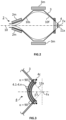
- a converting unit is traditionally formed by a number of bremsstrahlung converters (4.1-4.n) in the form of flat sheets of a high-Z number metal aligned one behind the other along the irradiation axis (Z) and separated from one another by cooling channels.
- bremsstrahlung converters 4.1-4.n
- Z irradiation axis
- the term "area" is therefore used when referring to the lengths hi or ci, letting the reader to mentally multiply the lengths hi and ci by a corresponding length in the second transverse direction (Y) to yield a magnitude in [m 2 ].
- Increasing the scanned area of bremsstrahlung crossed by the focused beam (10f) would be advantageous, in particular if a large number (n) of bremsstrahlung sheets are used, as the scanned area decreases after each sheet, thus increasing the concentration of the beam energy onto smaller scanned areas.
- the present invention proposes to replace the bremsstrahlung converters in the form of flat sheets used up to now in the art by curved bremsstrahlung converters (4.1-4.n) in the form of curved sheets, such that the focused beam (10f) intersects each of the one or more bremsstrahlung converters with an intersecting angle ( ⁇ ) comprised between 65° and 115° at all points, preferably between 75° and 105° at all points.
- the intersecting angle is 90°.
- An intersecting angle of 90° at all points of the converting unit (4) can be obtained with bremsstrahlung converters in the form of sheets having a single curvature or optionally double curvature of radius (di) defined as the distance separating the curved sheets from the first and optionally second focusing points (Fx, Fy). If the first and second focusing points are the same, the bremsstrahlung sheets have the geometry of a spherical cap of radius (di).
- the intersecting angle ( ⁇ ) can be brought closer to or even equal to 90° by locally tilting the bremsstrahlung sheet with respect to the irradiation direction parallel to the irradiation axis (Z) by an angle ⁇ .
- the intersecting angle ( ⁇ ) can be reduced to between 65° and 115° at all points, preferably between 75° and 105° at all points.
- bremsstrahlung converters (4.1-4.n) which are curved such that the focused beam (10f) intersects each of the one or more bremsstrahlung converters (4.1-4.n) with an intersecting angle ( ⁇ ) comprised between 65° and 115° at all points, clearly contributes to homogenizing over the scanned area of the bremsstrahlung converter the heat generated by the interaction with the focused beam. This renders the cooling of the converting unit easier than for flat sheets, and conventional cooling systems (4c) can be used with success.
- the one or more bremsstrahlung converters (4.1-4.n) can be in the shape of a section of cylinder, defined by a curved cross-section in the first transverse plane (X, Z), and generatrixes extending along a second transverse axis (Y), wherein X ⁇ Y ⁇ Z.
- This geometry is preferred in case the scanning unit (2) is configured for deviating the electron beam (10) along the predefined scanning pattern extending along the first transverse axis (X) only. It could also be preferred in case the target (5) has a length defining an elongated shape, and the scanned beam needs not be focused over a plane including the length of the elongated target.
- a converting unit (4) of this type is illustrated in Figure (c).
- the one or more bremsstrahlung converters (4.1-4.n) are in the shape of an ovoid cap, preferably a spherical cap, defined by a first curved cross-section in the first irradiation plane (X, Z) and by a second curved cross-section in the second irradiation plane (Y, Z).
- This type of converting unit is illustrated in Figure 1(b) and is particularly adapted in case the scanning unit (2) is configured for deviating the electron beam (10) along the predefined scanning pattern extending along the first transverse axis (X) and a second transverse axis (Y), wherein X ⁇ Y ⁇ Z, and the focusing unit (3) is configured for focusing the scanned beam (10s) also over a second irradiation plane (Y, Z) towards a second focusing point (Fy) located on the irradiation axis (Z), wherein the second focusing point (Fy) can be same as, or different from the first focusing point (Fx).
- the radius of curvature of the curved sections be constant, i.e., defining an arc of circle, or a spherical cap, respectively.
- the radius of curvature is preferably close to the distance (di) separating a bremsstrahlung converter (4.1-4.n) to the first focusing point (Fx).
- each of the one or more bremsstrahlung converters (4.1-4.n) has a first curved cross-section in the first irradiation plane (X, Z) defined by a substantially circular arc of radius (d1-dn) centred on the first focusing point (Fx).
- a " substantially circular arc " is defined herein as a curved segment having a radius of curvature which varies by not more than 10% over a length of the curved arc.
- the converting unit (4) comprises between 1 and n bremsstrahlung converters (4.1-4.n), wherein n is comprised between 2 and 8, preferably between 3 and 5, separated from one another by cooling channels.
- the converter cooling system (4c) can comprise gas or liquid forced cooling, with a cooling fluid flowing through the cooling channels to withdraw heat from the bremsstrahlung converters generated by the interaction with the focused beam (10f). This configuration defines what is herein referred to as "conventional cooling system" which is well known to the persons skilled in the art.
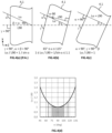
- Each of the one or more bremsstrahlung converters (4.1-4.n) has a thickness (L90) measured along a radius of curvature of not more than 3 mm, preferably the thickness (L90) is comprised between 0.2 and 2.5 mm, more preferably between 0.5 and 1.5 mm.
- the radius of curvature at one point of a bremsstrahlung converter is defined as the radius of a circle which touches the bremsstrahlung converter at that point and has the same tangent and curvature at that point. The radius of curvature is therefore normal to the tangent of the bremsstrahlung converter at that point. This is illustrated in Figures 4(a) to 4(c) , as indicated by L90.
- the thickness (L90) is also the shortest straight line crossing the bremsstrahlung converter from one surface to an opposite surface.
- the n th bremsstrahlung converter (4.n) in the sequence of n bremsstrahlung converters, which is located nearest the target holder (5h) has a larger thickness (L90) than the first bremsstrahlung converter (4.1) located nearest the focusing unit (3).
- each bremsstrahlung converter (4.i) in the sequence is thicker than the adjacent bremsstrahlung converter (4.(i-1)) located upstream, i.e., L90(4.i) > L90(4.(i-1)).
- the scanned areas of the bremsstrahlung converters decreases as the bremsstrahlung converters are nearer the first focusing point (Fx)
- increasing the thicknesses of the bremsstrahlung converters located downstream in the sequence allows homogenizing the volume of bremsstrahlung converter material interacting with the focused beam (10f). This way all bremsstrahlung converters contribute equally to the production of X-rays.
- the heating generated by the interaction which must be evacuated is also more homogeneously distributed between the various bremsstrahlung converters of the converting unit (4), thus facilitating the cooling thereof.
- the 1 to n bremsstrahlung converters (4.1-4.n) can be made of tantalum (Ta) ortungsten (W), or titanium (Ti).
- the system of the present invention is particularly suitable for targets (5) of small dimensions.
- the target (5) can be 226 Ra for producing 225 Ac commonly used for diagnostic imaging.
- Other examples of targets which can be used with the system of the present invention to form diagnostic imaging isotopes include 100 Mo-target for forming 99m Tc, or 186 W-target for producing 187 Re, or 134 Xe to form 131 I, or 68 Zn for producing 67 Cu, and the like.
- a target cooling system (5c) is provided, which is configured for cooling the target (5) when held in the target holder (5h).
- the target cooling system (5c) can comprise gas or liquid forced cooling, with a refrigerating fluid flowing through cooling channels in thermal contact with the target (5). Keeping the temperature of the target (5) below a degradation temperature is of course important.
- the sample holder can be configured for moving the target (5) such that a larger area of the target is scanned by the focusing point (which is static). This is particularly interesting in case of targets of larger dimensions, whose exposed area is larger than the converging area of the X-ray, so that transmutation occurs over a larger area / volume of the target than if it remained static.
- the system of the present invention can be used in a process for producing a radioisotope by X-ray irradiation of a target.
- the process comprises providing a system as described supra. After loading a target (5) onto the target holder (5h), scanning and focusing an accelerated electron beam onto the converting unit (4) to produce X-ray, to irradiate the target with the thus produced X-ray.
- the target can be for example, 226 Ra for producing 225 Ac, or 100 Mo-target for forming 99m Tc, or 186 W-target for producing 187 Re, or 134 Xe to form 131 I, or 68 Zn for producing 67 Cu, and the like.
Landscapes
- Physics & Mathematics (AREA)
- Engineering & Computer Science (AREA)
- General Engineering & Computer Science (AREA)
- High Energy & Nuclear Physics (AREA)
- Chemical & Material Sciences (AREA)
- Chemical Kinetics & Catalysis (AREA)
- General Chemical & Material Sciences (AREA)
- Spectroscopy & Molecular Physics (AREA)
- Particle Accelerators (AREA)
Claims (13)
- System zur Herstellung von Radioisotopen, umfassend,• einen Elektronenbeschleuniger (1), der dafür ausgelegt ist, einen Elektronenstrahl (10) aus beschleunigten Elektronen entlang einer Bestrahlungsachse (Z) erzeugen,• eine Abtasteinheit (2), die dafür ausgelegt ist, den Elektronenstrahl (10) entlang eines vordefinierten Abtastmusters abzulenken, um einen abgetasteten Strahl (10s) zu formen,• eine Fokussiereinheit (3), umfassend einen oder mehrere Magneten, die dafür ausgelegt sind, den abgetasteten Strahl (10s) über eine erste Bestrahlungsebene (X, Z) in Richtung eines ersten Fokussierpunkts (Fx) zu bündeln, der auf der Bestrahlungsachse (Z) liegt, um einen gebündelten Strahl (10f) zu formen, wobei die erste Bestrahlungsebene (X, Z) durch die Bestrahlungsachse (Z) und eine erste Transversalachse (X) definiert ist, wobei X ⊥ Z ist,• eine Konvertiereinheit (4), die sich zwischen der Fokussiereinheit (3) und dem ersten Fokussierpunkt (Fx) befindet, und umfassend einen oder mehrere Bremsstrahlungskonverter (4.1-4.n), die dafür ausgelegt sind, den gebündelten Strahl (10f) in einen Photonenstrahl (11x) umzuwandeln,• ein Konverterkühlsystem (4c), das dafür ausgelegt ist, die ein oder mehreren Bremsstrahlungskonverter (4.1-4.n) zu kühlen,• einen Zielhalter (5h), der dafür ausgelegt ist, ein Ziel (5) zu halten,wobei der Elektronenbeschleuniger (1), die Abtasteinheit (2), die Fokussiereinheit (3), die Konvertiereinheit (4) und der Zielhalter (5h) alle entlang der Bestrahlungsachse (Z) ausgerichtet und, in dieser Folge, einander nachgelagert angeordnet sind, wobei "nachgelagert" als relativ zur Elektronenstrahlrichtung definiert ist,dadurch gekennzeichnet, dass die ein oder mehreren Bremsstrahlungskonverter (4.1-4.n) gekrümmt sind, sodass der gebündelte Strahl (10f) jeden der ein oder mehreren Bremsstrahlungskonverter (4.1-4.n) mit einem Schnittwinkel (a) zwischen 65° und 115° an allen Punkten, vorzugsweise zwischen 75° und 105° an allen Punkten, schneidet.
- System gemäß Anspruch 1, wobei,• die Abtasteinheit (2) dafür ausgelegt ist, den Elektronenstrahl (10) entlang des vordefinierten Abtastmusters abzulenken, welches sich entlang der ersten Transversalachse (X) und einer zweiten Transversalachse (Y) erstreckt, wobei X ⊥ Y ⊥ Z ist,• die Fokussiereinheit (3) dafür ausgelegt ist, den abgetasteten Strahl (10s) außerdem über eine zweite Bestrahlungsebene (Y, Z) in Richtung eines zweiten Fokussierpunkts (Fy) zu bündeln, der auf der Bestrahlungsachse (Z) liegt,
wobei der zweite Fokussierpunkt (Fy) mit dem ersten Fokussierpunkt (Fx) identisch oder von diesem verschieden sein kann, und• die ein oder mehreren Bremsstrahlungskonverter (4.1-4.n) die Form einer eiförmigen Haube haben, vorzugsweise einer Kugelhaube, die durch einen ersten gekrümmten Querschnitt in der ersten Bestrahlungsebene (X, Z) und durch einen zweiten gekrümmten Querschnitt in der zweiten Bestrahlungsebene (Y, Z) definiert ist. - System gemäß Anspruch 1, wobei• die Abtasteinheit (2) dafür ausgelegt ist, den Elektronenstrahl (10) entlang des vordefinierten Abtastmusters abzulenken, welches sich nur entlang der ersten Transversalachse (X) erstreckt, und• die ein oder mehreren Bremsstrahlungskonverter (4.1-4.n) die Form eines Zylinderabschnitts haben, der durch einen gekrümmten Querschnitt in der ersten Transversalebene (X, Z) und Generatrizen definiert ist, die sich entlang einer zweiten Transversalachse (Y) erstrecken, wobei X ⊥ Y ⊥ Z ist.
- System gemäß einem der vorstehenden Ansprüche, wobei die Fokussiereinheit (3) dafür ausgelegt ist, den gebündelten Strahl (10f) mit einem Fokussierhalbwinkel (β) zu formen, der an dem ersten Fokussierpunkt (Fx) mit der Bestrahlungsachse (Z) auf der ersten Bestrahlungsebene (X, Z) zwischen 20 und 55°, vorzugsweise zwischen 30 und 45°, gebildet wird.
- System gemäß einem der vorstehenden Ansprüche, wobei jeder der ein oder mehreren Bremsstrahlungskonverter (4.1-4.n) einen ersten gekrümmten Querschnitt in der ersten Bestrahlungsebene (X, Z) aufweist, definiert durch einen im Wesentlichen kreisförmigen Radiusbogen (d1-dn), der auf den ersten Fokussierpunkt (Fx) zentriert ist, wobei ein "im Wesentlichen kreisförmiger Bogen" als ein gekrümmtes Segment definiert ist, das einen Krümmungsradius aufweist, der um nicht mehr als 10 % über eine Länge des gekrümmten Querschnitts variiert.
- System gemäß Anspruch 5, wobei jeder der ein oder mehreren Bremsstrahlungskonverter (4.1-4.n) einen zweiten gekrümmten Querschnitt in der zweiten Bestrahlungsebene (Y, Z) aufweist, definiert durch einen im Wesentlichen kreisförmigen Radiusbogen (d1-dn), der auf den zweiten Fokussierpunkt (Fy) zentriert ist, wobei der zweite Fokussierpunkt (Fy) vorzugsweise mit dem ersten Fokussierpunkt (Fx) identisch ist (d. h. Fx = Fy) .
- System gemäß einem der vorstehenden Ansprüche, wobei jeder der ein oder mehreren Bremsstrahlungskonverter (4.1-4.n) eine entlang eines Krümmungsradius gemessene Dicke (L90) von nicht mehr als 3 mm aufweist; vorzugsweise liegt die Dicke (L90) zwischen 0,2 und 2,5 mm, noch bevorzugter zwischen 0,5 und 1,5 mm.
- System gemäß einem der vorstehenden Ansprüche, wobei ein n-ter Bremsstrahlungskonverter (4.n), welcher dem Zielhalter (5h) am nächsten ist, eine größere Dicke (L90) aufweist als ein erster Bremsstrahlungskonverter (4.1), welcher der Fokussiereinheit (3) am nächsten ist.
- System gemäß einem der vorstehenden Ansprüche, wobei die Konvertiereinheit (4) zwischen 1 und n Bremsstrahlungskonverter (4.1-4.n) umfasst, wobei n zwischen 2 und 8 liegt, vorzugsweise zwischen 3 und 5, die durch Kühlkanäle voneinander getrennt sind.
- System gemäß einem der vorstehenden Ansprüche, wobei das Konverterkühlsystem (4c) eine Gas- oder Flüssigkeitszwangskühlung umfasst.
- System gemäß dem vorstehenden Anspruch, wobei die ein oder mehreren Bremsstrahlungskonverter (4.1-4.n) aus Tantalum (Ta) oder Wolfram (W) oder Titan (Ti) gefertigt sind.
- Prozess zum Herstellen eines Radioisotops durch Röntgenbestrahlung eines Ziels, umfassend• Bereitstellen eines Systems gemäß einem der vorstehenden Ansprüche,• Laden eines Ziels (5) in den Zielhalter (5h),• Abtasten und Bündeln eines beschleunigten Elektronenstrahls in die Konvertiereinheit (4), um einen Röntgenstrahl zu erzeugen,• Bestrahlen des Ziels mit dem so erzeugten Röntgenstrahl.
- Prozess gemäß dem vorstehenden Anspruch, wobei das Ziel (5) aus einem von 226Ra zum Herstellen von 225Ac oder 100Mo zum Bilden von 99mTc oder 186W zum Herstellen von 187Re oder 134Xe zum Bilden von 131I oder 68Zn zum Herstellen von 67Cu ausgewählt wird.
Priority Applications (6)
| Application Number | Priority Date | Filing Date | Title |
|---|---|---|---|
| EP22161257.5A EP4243036B1 (de) | 2022-03-10 | 2022-03-10 | System zur herstellung von radioisotopen durch bremsstrahlung mit einem gekrümmten wandler |
| CA3190852A CA3190852A1 (en) | 2022-03-10 | 2023-02-23 | System for production of radioisotopes by bremsstrahlung comprising a curved converter |
| JP2023030823A JP2023133177A (ja) | 2022-03-10 | 2023-03-01 | 湾曲したコンバータを伴う制動放射による放射性同位体の生成のためのシステム |
| KR1020230028737A KR20230133211A (ko) | 2022-03-10 | 2023-03-03 | 곡선 변환기를 포함하는 제동복사에 의한 방사성 동위원소 생산 시스템 |
| CN202310202229.2A CN116741427B (zh) | 2022-03-10 | 2023-03-05 | 包括弯曲转换器的用于通过轫致辐射生成放射性同位素的系统 |
| US18/119,898 US20230290532A1 (en) | 2022-03-10 | 2023-03-10 | System for production of radioisotopes by bremsstrahlung comprising a curved converter |
Applications Claiming Priority (1)
| Application Number | Priority Date | Filing Date | Title |
|---|---|---|---|
| EP22161257.5A EP4243036B1 (de) | 2022-03-10 | 2022-03-10 | System zur herstellung von radioisotopen durch bremsstrahlung mit einem gekrümmten wandler |
Publications (3)
| Publication Number | Publication Date |
|---|---|
| EP4243036A1 EP4243036A1 (de) | 2023-09-13 |
| EP4243036C0 EP4243036C0 (de) | 2024-08-21 |
| EP4243036B1 true EP4243036B1 (de) | 2024-08-21 |
Family
ID=80685483
Family Applications (1)
| Application Number | Title | Priority Date | Filing Date |
|---|---|---|---|
| EP22161257.5A Active EP4243036B1 (de) | 2022-03-10 | 2022-03-10 | System zur herstellung von radioisotopen durch bremsstrahlung mit einem gekrümmten wandler |
Country Status (6)
| Country | Link |
|---|---|
| US (1) | US20230290532A1 (de) |
| EP (1) | EP4243036B1 (de) |
| JP (1) | JP2023133177A (de) |
| KR (1) | KR20230133211A (de) |
| CN (1) | CN116741427B (de) |
| CA (1) | CA3190852A1 (de) |
Family Cites Families (13)
| Publication number | Priority date | Publication date | Assignee | Title |
|---|---|---|---|---|
| DE690618C (de) * | 1937-01-19 | 1940-04-30 | Siemens Reiniger Werke Akt Ges | Einrichtung zur Erzeugung eines konvergenten Roentgenstrahlenbuendels |
| DE921707C (de) * | 1940-10-29 | 1954-12-23 | Koch & Sterzel Ag | Einrichtung zur Erzeugung von Roentgenstrahlen |
| US2638554A (en) * | 1949-10-05 | 1953-05-12 | Bartow Beacons Inc | Directivity control of x-rays |
| AU4180799A (en) | 1998-04-10 | 1999-11-01 | Duke University | Methods and systems for the mass production of radioactive materials |
| FR2844916A1 (fr) * | 2002-09-25 | 2004-03-26 | Jacques Jean Joseph Gaudel | Source de rayonnement x a foyer virtuel ou fictif |
| EP1569243A1 (de) * | 2004-02-20 | 2005-08-31 | Ion Beam Applications S.A. | Targetvorrichtung zum Erzeugen eines Radioisotops |
| US7835499B2 (en) * | 2007-12-07 | 2010-11-16 | David U. Yu | Compact, short-pulse X-ray and T-ray fused source |
| CA2713972A1 (en) | 2010-07-27 | 2012-01-27 | Mevex Corporation | Power concentrator for electron and/or x-ray beams |
| EP2421006A1 (de) | 2010-08-20 | 2012-02-22 | Ludwig-Maximilians-Universität München | Verfahren zur Herstellung von Isotopen, insbesondere Verfahren zur Herstellung von Radioisotopen mittels Gammastrahlung |
| US20170076830A1 (en) * | 2015-05-02 | 2017-03-16 | Muons, Inc. | Energy recovery linac for radioisotope production with spatially-separated bremsstrahlung radiator and isotope production target |
| US11170907B2 (en) | 2015-11-06 | 2021-11-09 | Asml Netherlands B.V. | Radioisotope production |
| JP7169254B2 (ja) * | 2019-06-25 | 2022-11-10 | 株式会社日立製作所 | 放射性核種の製造方法及び装置 |
| CN114121331B (zh) * | 2021-11-26 | 2023-02-28 | 中山大学 | 强流电子直线加速器核素制备系统 |
-
2022
- 2022-03-10 EP EP22161257.5A patent/EP4243036B1/de active Active
-
2023
- 2023-02-23 CA CA3190852A patent/CA3190852A1/en active Pending
- 2023-03-01 JP JP2023030823A patent/JP2023133177A/ja active Pending
- 2023-03-03 KR KR1020230028737A patent/KR20230133211A/ko active Pending
- 2023-03-05 CN CN202310202229.2A patent/CN116741427B/zh active Active
- 2023-03-10 US US18/119,898 patent/US20230290532A1/en active Pending
Also Published As
| Publication number | Publication date |
|---|---|
| CA3190852A1 (en) | 2023-09-10 |
| EP4243036C0 (de) | 2024-08-21 |
| EP4243036A1 (de) | 2023-09-13 |
| CN116741427B (zh) | 2025-08-29 |
| KR20230133211A (ko) | 2023-09-19 |
| JP2023133177A (ja) | 2023-09-22 |
| CN116741427A (zh) | 2023-09-12 |
| US20230290532A1 (en) | 2023-09-14 |
Similar Documents
| Publication | Publication Date | Title |
|---|---|---|
| US5784423A (en) | Method of producing molybdenum-99 | |
| EP0555376B1 (de) | Vorrichtung zur steuerung von strahlung und ihre verwendungen | |
| AU691028B2 (en) | Superconducting cyclotron and target for use in the production of heavy isotopes | |
| EP2606489B1 (de) | Verfahren zur herstellung von isotopen, insbesondere verfahren zur herstellung von radioisotopen mittels bestrahlung mit gammastrahlen | |
| US6208704B1 (en) | Production of radioisotopes with a high specific activity by isotopic conversion | |
| JP7337090B2 (ja) | 中性子撮像システムおよび方法 | |
| Kumakhov | X-ray capillary optics: history of development and present status | |
| US12005274B2 (en) | High dose rate radiotherapy, system and method | |
| JP2020530107A (ja) | 収束x線イメージング形成装置及び方法 | |
| EP4243036B1 (de) | System zur herstellung von radioisotopen durch bremsstrahlung mit einem gekrümmten wandler | |
| Thisgaard et al. | Medium to large scale radioisotope production for targeted radiotherapy using a small PET cyclotron | |
| CN110400650B (zh) | 转换靶装置及靶材料层结构 | |
| US10720254B1 (en) | Production of radioactive isotope Cu-67 from gallium targets at electron accelerators | |
| US12567555B2 (en) | High dose rate radiotherapy systems and targets | |
| US12387899B2 (en) | Pebble bed beam converter | |
| Kumakhov | State and perspectives of capillary Roentgen optics | |
| Kelsey et al. | Gas target source for neutron radiation therapy | |
| Cheung et al. | Unpulsed high-energy radiation from the Crab pulsar and nebula | |
| McMahon et al. | Design and Development of the Advanced Diffraction and Scattering Beamlines at the Australian Synchrotron | |
| Burris-Mog | Spot Size Optimization of the Scorpius Accelerator | |
| Surrow | eRHIC—Accelerator and Detector Design | |
| TT | Supporting Online Material | |
| ARNDT | 6.1. X-ray sources |
Legal Events
| Date | Code | Title | Description |
|---|---|---|---|
| PUAI | Public reference made under article 153(3) epc to a published international application that has entered the european phase |
Free format text: ORIGINAL CODE: 0009012 |
|
| STAA | Information on the status of an ep patent application or granted ep patent |
Free format text: STATUS: THE APPLICATION HAS BEEN PUBLISHED |
|
| AK | Designated contracting states |
Kind code of ref document: A1 Designated state(s): AL AT BE BG CH CY CZ DE DK EE ES FI FR GB GR HR HU IE IS IT LI LT LU LV MC MK MT NL NO PL PT RO RS SE SI SK SM TR |
|
| STAA | Information on the status of an ep patent application or granted ep patent |
Free format text: STATUS: REQUEST FOR EXAMINATION WAS MADE |
|
| 17P | Request for examination filed |
Effective date: 20231013 |
|
| RBV | Designated contracting states (corrected) |
Designated state(s): AL AT BE BG CH CY CZ DE DK EE ES FI FR GB GR HR HU IE IS IT LI LT LU LV MC MK MT NL NO PL PT RO RS SE SI SK SM TR |
|
| GRAP | Despatch of communication of intention to grant a patent |
Free format text: ORIGINAL CODE: EPIDOSNIGR1 |
|
| STAA | Information on the status of an ep patent application or granted ep patent |
Free format text: STATUS: GRANT OF PATENT IS INTENDED |
|
| RIC1 | Information provided on ipc code assigned before grant |
Ipc: G21G 1/00 20060101ALN20240226BHEP Ipc: H05H 6/00 20060101ALI20240226BHEP Ipc: H01J 35/14 20060101ALI20240226BHEP Ipc: G21G 1/12 20060101AFI20240226BHEP |
|
| INTG | Intention to grant announced |
Effective date: 20240319 |
|
| GRAS | Grant fee paid |
Free format text: ORIGINAL CODE: EPIDOSNIGR3 |
|
| GRAA | (expected) grant |
Free format text: ORIGINAL CODE: 0009210 |
|
| STAA | Information on the status of an ep patent application or granted ep patent |
Free format text: STATUS: THE PATENT HAS BEEN GRANTED |
|
| AK | Designated contracting states |
Kind code of ref document: B1 Designated state(s): AL AT BE BG CH CY CZ DE DK EE ES FI FR GB GR HR HU IE IS IT LI LT LU LV MC MK MT NL NO PL PT RO RS SE SI SK SM TR |
|
| REG | Reference to a national code |
Ref country code: GB Ref legal event code: FG4D |
|
| REG | Reference to a national code |
Ref country code: CH Ref legal event code: EP |
|
| REG | Reference to a national code |
Ref country code: DE Ref legal event code: R096 Ref document number: 602022005402 Country of ref document: DE |
|
| REG | Reference to a national code |
Ref country code: IE Ref legal event code: FG4D |
|
| U01 | Request for unitary effect filed |
Effective date: 20240906 |
|
| U07 | Unitary effect registered |
Designated state(s): AT BE BG DE DK EE FI FR IT LT LU LV MT NL PT RO SE SI Effective date: 20240927 |
|
| PG25 | Lapsed in a contracting state [announced via postgrant information from national office to epo] |
Ref country code: NO Free format text: LAPSE BECAUSE OF FAILURE TO SUBMIT A TRANSLATION OF THE DESCRIPTION OR TO PAY THE FEE WITHIN THE PRESCRIBED TIME-LIMIT Effective date: 20241121 |
|
| PG25 | Lapsed in a contracting state [announced via postgrant information from national office to epo] |
Ref country code: PL Free format text: LAPSE BECAUSE OF FAILURE TO SUBMIT A TRANSLATION OF THE DESCRIPTION OR TO PAY THE FEE WITHIN THE PRESCRIBED TIME-LIMIT Effective date: 20240821 Ref country code: GR Free format text: LAPSE BECAUSE OF FAILURE TO SUBMIT A TRANSLATION OF THE DESCRIPTION OR TO PAY THE FEE WITHIN THE PRESCRIBED TIME-LIMIT Effective date: 20241122 |
|
| PG25 | Lapsed in a contracting state [announced via postgrant information from national office to epo] |
Ref country code: IS Free format text: LAPSE BECAUSE OF FAILURE TO SUBMIT A TRANSLATION OF THE DESCRIPTION OR TO PAY THE FEE WITHIN THE PRESCRIBED TIME-LIMIT Effective date: 20241221 |
|
| PG25 | Lapsed in a contracting state [announced via postgrant information from national office to epo] |
Ref country code: HR Free format text: LAPSE BECAUSE OF FAILURE TO SUBMIT A TRANSLATION OF THE DESCRIPTION OR TO PAY THE FEE WITHIN THE PRESCRIBED TIME-LIMIT Effective date: 20240821 |
|
| PG25 | Lapsed in a contracting state [announced via postgrant information from national office to epo] |
Ref country code: RS Free format text: LAPSE BECAUSE OF FAILURE TO SUBMIT A TRANSLATION OF THE DESCRIPTION OR TO PAY THE FEE WITHIN THE PRESCRIBED TIME-LIMIT Effective date: 20241121 Ref country code: ES Free format text: LAPSE BECAUSE OF FAILURE TO SUBMIT A TRANSLATION OF THE DESCRIPTION OR TO PAY THE FEE WITHIN THE PRESCRIBED TIME-LIMIT Effective date: 20240821 |
|
| PG25 | Lapsed in a contracting state [announced via postgrant information from national office to epo] |
Ref country code: RS Free format text: LAPSE BECAUSE OF FAILURE TO SUBMIT A TRANSLATION OF THE DESCRIPTION OR TO PAY THE FEE WITHIN THE PRESCRIBED TIME-LIMIT Effective date: 20241121 Ref country code: PL Free format text: LAPSE BECAUSE OF FAILURE TO SUBMIT A TRANSLATION OF THE DESCRIPTION OR TO PAY THE FEE WITHIN THE PRESCRIBED TIME-LIMIT Effective date: 20240821 Ref country code: NO Free format text: LAPSE BECAUSE OF FAILURE TO SUBMIT A TRANSLATION OF THE DESCRIPTION OR TO PAY THE FEE WITHIN THE PRESCRIBED TIME-LIMIT Effective date: 20241121 Ref country code: IS Free format text: LAPSE BECAUSE OF FAILURE TO SUBMIT A TRANSLATION OF THE DESCRIPTION OR TO PAY THE FEE WITHIN THE PRESCRIBED TIME-LIMIT Effective date: 20241221 Ref country code: HR Free format text: LAPSE BECAUSE OF FAILURE TO SUBMIT A TRANSLATION OF THE DESCRIPTION OR TO PAY THE FEE WITHIN THE PRESCRIBED TIME-LIMIT Effective date: 20240821 Ref country code: GR Free format text: LAPSE BECAUSE OF FAILURE TO SUBMIT A TRANSLATION OF THE DESCRIPTION OR TO PAY THE FEE WITHIN THE PRESCRIBED TIME-LIMIT Effective date: 20241122 Ref country code: ES Free format text: LAPSE BECAUSE OF FAILURE TO SUBMIT A TRANSLATION OF THE DESCRIPTION OR TO PAY THE FEE WITHIN THE PRESCRIBED TIME-LIMIT Effective date: 20240821 |
|
| PG25 | Lapsed in a contracting state [announced via postgrant information from national office to epo] |
Ref country code: SM Free format text: LAPSE BECAUSE OF FAILURE TO SUBMIT A TRANSLATION OF THE DESCRIPTION OR TO PAY THE FEE WITHIN THE PRESCRIBED TIME-LIMIT Effective date: 20240821 |
|
| PG25 | Lapsed in a contracting state [announced via postgrant information from national office to epo] |
Ref country code: CZ Free format text: LAPSE BECAUSE OF FAILURE TO SUBMIT A TRANSLATION OF THE DESCRIPTION OR TO PAY THE FEE WITHIN THE PRESCRIBED TIME-LIMIT Effective date: 20240821 |
|
| PG25 | Lapsed in a contracting state [announced via postgrant information from national office to epo] |
Ref country code: SK Free format text: LAPSE BECAUSE OF FAILURE TO SUBMIT A TRANSLATION OF THE DESCRIPTION OR TO PAY THE FEE WITHIN THE PRESCRIBED TIME-LIMIT Effective date: 20240821 |
|
| U20 | Renewal fee for the european patent with unitary effect paid |
Year of fee payment: 4 Effective date: 20250327 |
|
| PLBE | No opposition filed within time limit |
Free format text: ORIGINAL CODE: 0009261 |
|
| STAA | Information on the status of an ep patent application or granted ep patent |
Free format text: STATUS: NO OPPOSITION FILED WITHIN TIME LIMIT |
|
| 26N | No opposition filed |
Effective date: 20250522 |
|
| PG25 | Lapsed in a contracting state [announced via postgrant information from national office to epo] |
Ref country code: MC Free format text: LAPSE BECAUSE OF FAILURE TO SUBMIT A TRANSLATION OF THE DESCRIPTION OR TO PAY THE FEE WITHIN THE PRESCRIBED TIME-LIMIT Effective date: 20240821 |
|
| REG | Reference to a national code |
Ref country code: CH Ref legal event code: H13 Free format text: ST27 STATUS EVENT CODE: U-0-0-H10-H13 (AS PROVIDED BY THE NATIONAL OFFICE) Effective date: 20251024 |
|
| PG25 | Lapsed in a contracting state [announced via postgrant information from national office to epo] |
Ref country code: CH Free format text: LAPSE BECAUSE OF NON-PAYMENT OF DUE FEES Effective date: 20250331 |
|
| PG25 | Lapsed in a contracting state [announced via postgrant information from national office to epo] |
Ref country code: IE Free format text: LAPSE BECAUSE OF NON-PAYMENT OF DUE FEES Effective date: 20250310 |
|
| PGFP | Annual fee paid to national office [announced via postgrant information from national office to epo] |
Ref country code: GB Payment date: 20260327 Year of fee payment: 5 |