EP2605367A1 - Machine à flux transversal dotée de structures de Halbach - Google Patents
Machine à flux transversal dotée de structures de Halbach Download PDFInfo
- Publication number
- EP2605367A1 EP2605367A1 EP11192978.2A EP11192978A EP2605367A1 EP 2605367 A1 EP2605367 A1 EP 2605367A1 EP 11192978 A EP11192978 A EP 11192978A EP 2605367 A1 EP2605367 A1 EP 2605367A1
- Authority
- EP
- European Patent Office
- Prior art keywords
- active part
- movement
- halbach
- magnetic
- flux machine
- Prior art date
- Legal status (The legal status is an assumption and is not a legal conclusion. Google has not performed a legal analysis and makes no representation as to the accuracy of the status listed.)
- Withdrawn
Links
Images


Classifications
-
- H—ELECTRICITY
- H02—GENERATION; CONVERSION OR DISTRIBUTION OF ELECTRIC POWER
- H02K—DYNAMO-ELECTRIC MACHINES
- H02K1/00—Details of the magnetic circuit
- H02K1/06—Details of the magnetic circuit characterised by the shape, form or construction
- H02K1/12—Stationary parts of the magnetic circuit
- H02K1/14—Stator cores with salient poles
-
- H—ELECTRICITY
- H02—GENERATION; CONVERSION OR DISTRIBUTION OF ELECTRIC POWER
- H02K—DYNAMO-ELECTRIC MACHINES
- H02K1/00—Details of the magnetic circuit
- H02K1/06—Details of the magnetic circuit characterised by the shape, form or construction
- H02K1/22—Rotating parts of the magnetic circuit
- H02K1/27—Rotor cores with permanent magnets
- H02K1/2706—Inner rotors
- H02K1/272—Inner rotors the magnetisation axis of the magnets being perpendicular to the rotor axis
- H02K1/274—Inner rotors the magnetisation axis of the magnets being perpendicular to the rotor axis the rotor consisting of two or more circumferentially positioned magnets
- H02K1/2753—Inner rotors the magnetisation axis of the magnets being perpendicular to the rotor axis the rotor consisting of two or more circumferentially positioned magnets the rotor consisting of magnets or groups of magnets arranged with alternating polarity
- H02K1/278—Surface mounted magnets; Inset magnets
- H02K1/2783—Surface mounted magnets; Inset magnets with magnets arranged in Halbach arrays
-
- H—ELECTRICITY
- H02—GENERATION; CONVERSION OR DISTRIBUTION OF ELECTRIC POWER
- H02K—DYNAMO-ELECTRIC MACHINES
- H02K26/00—Machines adapted to function as torque motors, i.e. to exert a torque when stalled
-
- H—ELECTRICITY
- H02—GENERATION; CONVERSION OR DISTRIBUTION OF ELECTRIC POWER
- H02K—DYNAMO-ELECTRIC MACHINES
- H02K41/00—Propulsion systems in which a rigid body is moved along a path due to dynamo-electric interaction between the body and a magnetic field travelling along the path
-
- H—ELECTRICITY
- H02—GENERATION; CONVERSION OR DISTRIBUTION OF ELECTRIC POWER
- H02K—DYNAMO-ELECTRIC MACHINES
- H02K2201/00—Specific aspects not provided for in the other groups of this subclass relating to the magnetic circuits
- H02K2201/12—Transversal flux machines
Definitions
- the present invention relates to a transversal flux machine having a first active part and a second active part, which is in magnetic interaction with it for movement along a predetermined direction of movement relative to the first active part, wherein the second active part is equipped with a magnetic device.
- Transverse flux motors as rotary or torque motors are characterized by a ring winding, and the magnetic flux is transverse (perpendicular) to the plane of rotation.
- each phase usually has its own permanent excitation.
- transverse flux motors are also known in which the three phases are fed by only one permanent magnet system. Transverse flux motors have the ability to realize high pole pairs and thus have small pole pitches. Thus, the dead weight per pole is small and consequently results in a favorable power to weight ratio. Due to the ring winding in transverse flux motors, the winding heads are eliminated.
- At least a part of the pole elements of the stator is made of magnetically isotropic material, for example of magnetic sintered material.
- EP 1 005 136 A1 a single- or multi-phase transversal flux machine with permanent magnets arranged on the rotor in the circumferential direction in a number corresponding to the number of poles of the machine with flux guides possibly arranged between the permanent magnets, and with U-yokes arranged sequentially in the circumferential direction on the stator.
- the U-yokes and or or the permanent magnets or flux guides are compared with a direction parallel to the axis of rotation of the machine advantageously offset by a pole pitch or odd multiple of the pole pitch offset.
- the object of the present invention is to further increase the power density of a transverse flux machine.
- the transverse flux machine is equipped with a magnetic device having one or more Halbach arrays.
- Halbach arrays have a continuously changing direction of magnetization or represent a special configuration of permanent magnet segments whose magnetization direction is tilted against each other by a certain angle in the direction of the longitudinal axis of the array. This increases the flux density on one side of the Halbach array and attenuates it on the opposite side.
- high-weight flow collectors can be dispensed with, so that ultimately the power density of the transverse flux machine increases.
- a plurality of Halbach arrays can be arranged spaced from each other in the direction of movement on the second active part, wherein the Halbach arrays in the second active part cause a magnetic flux perpendicular to the direction of movement. It can be provided that in the direction of movement only a magnetic return element is arranged on every second half of the Halbach arrays on the first active part. As a result, the weight of the transverse flux machine can be further reduced.
- the second active part has two spaced Halbach arrays, which extend in the direction of movement parallel to each other and substantially over the total extent of the second active part, so that in the second active part, a magnetic flux is caused parallel to the direction of movement.
- the first active part in the direction of movement may alternately have I- and U-shaped return elements, wherein an electrical conductor passes through the U-shaped return elements. This allows the magnetic flux to be closed around the track.
- the first active part magnetic return elements which are skewed relative to the direction of movement by a pole pitch. Due to the skew, the magnetic flux can take a very short path.
- the transverse flux machine is preferably a three-phase machine, the second active part having a triangular cross-section perpendicular to the direction of movement, Halbach arrays being arranged on three lateral surfaces of the second active part and each Halbach array on one of the lateral surfaces being a respective Halbach -Array is offset electrically on another of the lateral surfaces by 120 °.
- the transversal flux machine can also be used for the usual three-phase three-phase current system.
- the one or more Halbach arrays have a plurality of segments along their respective longitudinal axis, wherein the magnetic orientations of two adjacent ones of the segments in the direction of the longitudinal axis are each preferably tilted at 45 °, 90 ° or another predetermined angle other than 0 °.
- the appropriate graduation ie the tilt angle from segment to segment, can be defined.
- the magnetization changes continuously, in particular sinusoidally.
- the transverse flux machine is preferably designed as a multi-phase torque motor. But it can also be realized for example as a linear motor or as a generator.
- the second active part with the Halbach arrays preferably represents the rotor.
- the rotor can be made very low mass.
- the second active part is the moving part, in particular the secondary part. By a low-mass secondary part can in turn achieve a high dynamics of the engine.
- the second active part is hollow and flows through a coolant. With the cooling in the interior of the second active part, a higher power density can be realized.
- the present invention relates to a multiphase transversal flux machine.
- the following examples relate to three-phase transversal flux motors, but their design principle can also be applied to other transversal flux machines.
- FIG. 7 The basic structure of a transversal flux motor for three phases can be found in FIG. 7 be recognized.
- This is a torque motor, which represents a closed ring.
- a rotor with for example triangular cross-section, as in FIG. 6 is indicated.
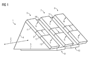
- a section of such a rotor is also in FIG. 1 shown.
- the rotor is annular and has a triangular cross section here.
- the second active part of the transverse flux machine, ie the rotor 1 has in the direction of movement 2 (in FIG. 1 indicated by a double arrow, since the movement can take place in both directions) in sections substantially the shape of a prism.
- Such a prism-shaped portion of the rotor 1 is in FIG. 1 played.
- the rotor ring or the triangular prism has three side surfaces 3, 4 and 5.
- Magnetic Halbach arrays 6, 7, 8 are shown only on the side surface 3.
- the Halbach arrays 9, 10 are merely indicated.
- the Halbach arrays 6 to 10 are arranged on the rotor 1 perpendicular to the direction of movement 2. Ie. the longitudinal axis of each Halbach array 6 to 10 extends transversely to the direction of movement 2. Between two Halbach arrays 6, 7, 8 is in each case a gap 14, 15th
- the Halbach array 6 exists of several segments 11, 12, 13.
- the magnetization direction of the first segment 11 has on its surface perpendicular to the outside.
- the segment can therefore be referred to as north pole N.
- the magnetization direction of the segment 13 is perpendicular to the surface, so that a south pole S results.
- FIG. 2 is the rotor of FIG. 1 presented in unwound form. That is, the side surfaces 3, 4 and 5 are shown side by side. There are also the Halbach arrays 6, 7, 8 on the side 3 and the Halbach arrays 9, 10 on the other side surface 5 can be seen.
- the Halbach arrays of page 5 are offset from the Halbach arrays of page 3 by 120 ° electrically.
- the electrical phase shift is in FIG. 2 shown on the left. It can thus be seen immediately that the Halbach array 9 is electrically offset by 120 ° with respect to the Halbach array 6.
- the 120 ° results from the three-phase system.
- the Halbach arrays on page 4 are also offset from those of page 5 by 120 ° electrically. The same applies between the Halbach arrays of page 4 and page 3.
- FIG. 2 has a Halbach array in the direction of movement 2, the width of 120 ° electrical.
- a gap 14, 15 has the width of 60 ° electrical.
- the width of the Halbach arrays and the gaps can be freely selected within certain limits. In sum, in the present configuration, 180 ° must electrically result, so that For example, a Halbach array width of 100 ° and a gap width of 80 ° could be chosen in principle.
- the first active part here the stator, has magnetic conclusions 16, 17, 18, which repeat in the direction of movement 2 to 360 ° electrically.
- the conclusions 16, 17, 18 extend in the plan view of FIG. 2 congruent with the underlying Halbach arrays and thus extend perpendicular to the direction of movement. 2
- FIG. 3 is a short section (two pole pitches) of a transverse flux motor with a rotor of FIG. 1 respectively.
- FIG. 2 shown.
- the arcuate conclusions 16, 17 and 18 are part of the first active part of the transverse flux machine, so here the stator 40.
- Each of the conclusions 16, 17, 18 extends around a respective conductor 19, 20, 21, the phases U, V and W of Three-phase system lead.
- the conclusions 16 to 18 may be formed from a ferromagnetic powder material (eg SMC - Soft Magnetic Composite) or from electrical steel sheets. They also have a width of 120 ° electrically and are arranged around the rotor without offset to each other. On average, therefore, there is a magnetic inference of the stator 2 over every second Halbach array of the rotor 1.
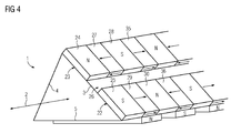
- FIG. 4 Another embodiment of a transverse flux machine according to the invention is in the 4 to FIG. 8 shown.
- a rotor 1 is shown, which in principle the structure of the rotor of FIG. 1
- two Halbach arrays 22, 23 extend along the direction of movement 2. That is, the longitudinal axes of the Halbach arrays extend in the direction of movement 2, which also means that the individual magnetically differently oriented segments are arranged one behind the other in the direction of movement 2.
- the orientations of the individual segments of the Halbach arrays result from the designations N and S as well as from the in FIG. 4 drawn Arrows. From the north poles N, the magnetic orientation points to the outside and the south poles S to the inside.
- the gap 25 extends like the Halbach arrays along the entire rotor 1.
- a magnetic segment 27 whose magnetic orientation to the Nordpolsegment 24, and a Südpolsegment 28 and a magnetic segment 35 whose magnetization directed away from the South Polsegment is in the Halbach array 23.
- Halbach array 22 closes in the direction of movement of the Südpolsegment 25, a magnetic segment 29 whose magnetic orientation of the Südpolsegment 26 points away, and a Nordpolsegment 30 and a magnet segment 36 whose magnetization is directed to the Nordpolsegment towards.
- This Halbach Geneva Coordinats for both Halbach arrays 22, 23 in the direction of movement 2.
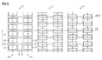
- FIG. 5 the rotor 1 is again shown in unwound form. Again, it can be seen that the Halbach arrays 22 and 23 continue virtually infinite. In an angular range of 360 ° electrical are on average two poles, namely a south pole S and a north pole N. The magnetic segments 27, 29 with magnetic orientation parallel to the direction of movement 2 are in FIG. 5 merely symbolized by arrows.
- Perpendicular to the Halbach arrays are located alternately in the direction of movement U-cores 31 and I-cores 32 of the stator. Each of these cores provides an inference from one north pole to an opposite south pole in the other Halbach array. In FIG. 5 these U-cores and I-cores are shown in broken lines.
- the course of the flow proceeds, for example, out of a north pole segment N into a U core 31 to a south pole segment S (flow in the radial direction), from there via a Halbach segment to an in FIG. 5 underlying north pole segment N (circumferential flow) and thence via an I core to a south pole segment S of the opposite Halbach array (radial flow) and thence back to the output north pole segment via an intermediate Halbach segment (flux in FIG direction of movement).
- the flow is carried out via the respective electrical conductor in the U-cores and under the conductor between the rotor and conductor in the I-cores.
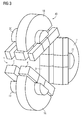
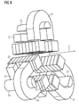
- This flow guide 33 is from a different perspective (viewing direction along the direction of movement 2) in FIG FIG. 6 shown.
- the cross section through the transverse flux machine of FIG. 6 shows U-cores 31 and I-cores 32.
- the magnetic flux in the case of the conductor 19 thus runs around it through the U-core 31 to the Halbach array 22 and through the I-core 32 back from the Halbach array 22 to the Halbach array 23rd
- FIG. 6 A support structure of the Halbach arrays is in FIG. 6 not shown. Between the stator-side U and I cores and the rotor-side Halbach arrays is in each case an air gap. In principle, the I-cores can also be dispensed with. However, this increases the leakage flux
- FIG. 7 The entire ring structure of a transverse flux machine having such a construction is shown in FIG. 7 played.
- the U cores 31 and the I cores 32 are identically distributed on the circumference. Over the I-cores 32 and under the U-cores 31 the conductor 19 runs.
- FIG. 8 shows similar to FIG. 3 a short section of the ring of FIG. 7 or a corresponding transverse flux motor.
- the Halbach arrays 22, 23 running in the direction of movement 2 here have a square cross-section. However, they can also, for example, have a triangular cross-section so that the Halbach arrays located at the tips of the triangle can be arranged closer to each other.
- the Half-axis segments are shown here very briefly in the direction of movement. This is to symbolize that in successive half-axis segments, the magnetic orientation can not only be tilted by 90 °, but also with a different angle, eg 45 °, etc.
- FIG. 9 is a further embodiment of a rotor of a Transversal Wegmotors invention shown.
- only one Halbach array 34 is necessary on each side 3, 4, 5 of the rotor with triangular cross-section.
- the Halbach array 34 also extends in the direction of movement 2.
- the Halbach arrays are not offset on the three side surfaces 3, 4 and 5 to each other. Therefore, here are stator yokes (in FIG. 9 not shown), which are skewed. That is to say that a conclusion must, for example, run from the north pole segment N, at the top of the side face 3, to the south pole segment S, at the bottom of the side face 4.
- the pole pitch ⁇ p corresponds to the distance between the north pole segment N and the south pole segment S, relative to the center thereof.
- each phase has its own permanent excitation.
- the excitation occurs here by Halbach arrays, which are located on the three sides of the rotor with a triangular cross-section. Due to the Halbach magnets eliminates the iron-bearing flow collector, which is necessary when in the transverse flux machine only permanent magnets in bipolar arrangement in the second active part or used in the rotor or rotor.
- the rotor or rotor can therefore be formed by a (ring-shaped) non-magnetically conductive core (eg A-magnetic steel or aluminum).
- the core can also be hollow to dissipate the rotor heat with a coolant or with a heat pipe.
- a pole pair is always shown with a north pole and a south pole and a magnetic segment therebetween whose magnetic orientation is tilted by 90 °. At the end of a pole pair, such a magnet segment is also added.
- a pole pair can also be implemented, for example, from five subsegments.
- the additional magnet segments then have a magnetization direction of, for example, 45 ° and are respectively inserted between the poles and the orthogonally magnetized magnet pieces.
- the segmentation of the Halbach arrays can also be further refined, wherein the tilt angle of the magnetization direction is then further reduced from segment to segment.
- the triangles When realizing a transversal flux machine for three phases with rotor, which has a triangular cross-section, the triangles can be flattened at their acute corners.
- the internal "triangle" rotor
- the internal "triangle" can be attached to a rotation bracket and connected to the rotor hub.
- the rotors have a triangular cross-section. However, they can in principle also have a different cross-section, for example a horseshoe-shaped, a square or another polygonal cross-section.
- the rotor may also be hexagonal, wherein the supply of 2. 3 phases takes place to compensate for the pulsating forces of attraction (sin 2 forces).
- a support structure can be constructed, in which the individual conclusions are accurately inserted and the toroidal coils are hung. The potting or impregnation of the ring winding can then take place in this support structure. Possibly. It is also possible to insert stiffeners made of fiber composite materials.
- a three-phase transverse flux motor with staggered Halbach arrays can be realized on the sides of a rotor of triangular cross-section, connecting all three phases to the exciter flux.
- stator ring lines can be provided with liquid cooling (eg water or oil).
- liquid cooling eg water or oil.
- current densities of 80 to 100 A / mm 2 are possible.
- the air gap induction between rotor and stator can be designed across the thickness of the permanent magnets or Halbach arrays.
- a very high utilization can be achieved because the LuftspaltindutationsSub can be set by 50% higher and the current density due to the short loop by a factor of ten.
- the design of the air gap induction and the multi-phase arrangement, the noise and the torque ripple can be optimized.
- the greatest advantage of the transverse flux machine according to the invention is that flow collectors in the rotor or rotor and thus their weight can be saved.
- the stator yokes need not necessarily be skewed so that they can be made easier.
Priority Applications (3)
| Application Number | Priority Date | Filing Date | Title |
|---|---|---|---|
| EP11192978.2A EP2605367A1 (fr) | 2011-12-12 | 2011-12-12 | Machine à flux transversal dotée de structures de Halbach |
| PCT/EP2012/073790 WO2013087412A1 (fr) | 2011-12-12 | 2012-11-28 | Machine à flux transversal à ensembles halbach |
| EP12798253.6A EP2792051A1 (fr) | 2011-12-12 | 2012-11-28 | Machine à flux transversal à ensembles halbach |
Applications Claiming Priority (1)
| Application Number | Priority Date | Filing Date | Title |
|---|---|---|---|
| EP11192978.2A EP2605367A1 (fr) | 2011-12-12 | 2011-12-12 | Machine à flux transversal dotée de structures de Halbach |
Publications (1)
| Publication Number | Publication Date |
|---|---|
| EP2605367A1 true EP2605367A1 (fr) | 2013-06-19 |
Family
ID=47324120
Family Applications (2)
| Application Number | Title | Priority Date | Filing Date |
|---|---|---|---|
| EP11192978.2A Withdrawn EP2605367A1 (fr) | 2011-12-12 | 2011-12-12 | Machine à flux transversal dotée de structures de Halbach |
| EP12798253.6A Withdrawn EP2792051A1 (fr) | 2011-12-12 | 2012-11-28 | Machine à flux transversal à ensembles halbach |
Family Applications After (1)
| Application Number | Title | Priority Date | Filing Date |
|---|---|---|---|
| EP12798253.6A Withdrawn EP2792051A1 (fr) | 2011-12-12 | 2012-11-28 | Machine à flux transversal à ensembles halbach |
Country Status (2)
| Country | Link |
|---|---|
| EP (2) | EP2605367A1 (fr) |
| WO (1) | WO2013087412A1 (fr) |
Cited By (5)
| Publication number | Priority date | Publication date | Assignee | Title |
|---|---|---|---|---|
| DE102015210032A1 (de) * | 2015-06-01 | 2016-12-01 | Siemens Aktiengesellschaft | Mehrphasige Transversalflussmaschine |
| DE102019215015A1 (de) * | 2019-09-30 | 2021-04-01 | Rolls-Royce Deutschland Ltd & Co Kg | Transversalflussmaschine |
| US11824410B1 (en) | 2023-01-11 | 2023-11-21 | Rolls-Royce Deutschland Ltd & Co Kg | Electrical machines for aircraft power and propulsion systems |
| US11827371B1 (en) | 2023-01-11 | 2023-11-28 | Rolls-Royce Deutschland Ltd & Co Kg | Electrical machines for aircraft power and propulsion systems |
| US11973385B1 (en) | 2023-01-11 | 2024-04-30 | Rolls-Royce Deutschland Ltd & Co Kg | Electrical machines for aircraft power and propulsion systems |
Families Citing this family (1)
| Publication number | Priority date | Publication date | Assignee | Title |
|---|---|---|---|---|
| CN108494122B (zh) * | 2018-04-25 | 2019-08-30 | 华中科技大学 | 一种横向磁通永磁电机 |
Citations (3)
| Publication number | Priority date | Publication date | Assignee | Title |
|---|---|---|---|---|
| EP1005136A1 (fr) | 1998-11-27 | 2000-05-31 | DaimlerChrysler AG | Machine à flux transversal à une ou plusieurs phases |
| EP1063754A2 (fr) | 1999-06-22 | 2000-12-27 | DaimlerChrysler AG | Machine à flux transversal |
| US20080309171A1 (en) * | 2004-11-11 | 2008-12-18 | Abb Research Ltd. | Linear Transverse Flux Machine |
Family Cites Families (1)
| Publication number | Priority date | Publication date | Assignee | Title |
|---|---|---|---|---|
| DE102010015441A1 (de) * | 2010-04-16 | 2011-10-20 | Fachhochschule Gelsenkirchen | Transversalflussmaschine und Verfahren zur Herstellung derselben |
-
2011
- 2011-12-12 EP EP11192978.2A patent/EP2605367A1/fr not_active Withdrawn
-
2012
- 2012-11-28 WO PCT/EP2012/073790 patent/WO2013087412A1/fr active Application Filing
- 2012-11-28 EP EP12798253.6A patent/EP2792051A1/fr not_active Withdrawn
Patent Citations (3)
| Publication number | Priority date | Publication date | Assignee | Title |
|---|---|---|---|---|
| EP1005136A1 (fr) | 1998-11-27 | 2000-05-31 | DaimlerChrysler AG | Machine à flux transversal à une ou plusieurs phases |
| EP1063754A2 (fr) | 1999-06-22 | 2000-12-27 | DaimlerChrysler AG | Machine à flux transversal |
| US20080309171A1 (en) * | 2004-11-11 | 2008-12-18 | Abb Research Ltd. | Linear Transverse Flux Machine |
Cited By (11)
| Publication number | Priority date | Publication date | Assignee | Title |
|---|---|---|---|---|
| DE102015210032A1 (de) * | 2015-06-01 | 2016-12-01 | Siemens Aktiengesellschaft | Mehrphasige Transversalflussmaschine |
| WO2016192881A1 (fr) * | 2015-06-01 | 2016-12-08 | Siemens Aktiengesellschaft | Machine polyphasée à flux transversal |
| CN107660323A (zh) * | 2015-06-01 | 2018-02-02 | 西门子公司 | 多相横向磁通电机 |
| US10326344B2 (en) | 2015-06-01 | 2019-06-18 | Siemens Aktiengesellschaft | Polyphase transverse flux machine |
| CN107660323B (zh) * | 2015-06-01 | 2021-08-13 | 劳斯莱斯德国有限两合公司 | 多相横向磁通电机 |
| DE102019215015A1 (de) * | 2019-09-30 | 2021-04-01 | Rolls-Royce Deutschland Ltd & Co Kg | Transversalflussmaschine |
| US11611247B2 (en) | 2019-09-30 | 2023-03-21 | Rolls-Royce Deutschland Ltd & Co Kg | Transverse flux machine |
| US11799331B2 (en) | 2019-09-30 | 2023-10-24 | Rolls-Royce Deutschland Ltd & Co Kg | Transverse flux machine |
| US11824410B1 (en) | 2023-01-11 | 2023-11-21 | Rolls-Royce Deutschland Ltd & Co Kg | Electrical machines for aircraft power and propulsion systems |
| US11827371B1 (en) | 2023-01-11 | 2023-11-28 | Rolls-Royce Deutschland Ltd & Co Kg | Electrical machines for aircraft power and propulsion systems |
| US11973385B1 (en) | 2023-01-11 | 2024-04-30 | Rolls-Royce Deutschland Ltd & Co Kg | Electrical machines for aircraft power and propulsion systems |
Also Published As
| Publication number | Publication date |
|---|---|
| WO2013087412A1 (fr) | 2013-06-20 |
| EP2792051A1 (fr) | 2014-10-22 |
Similar Documents
| Publication | Publication Date | Title |
|---|---|---|
| EP2639936B1 (fr) | Machine électrique à rotor excité en permanence et rotor excité en permanence correspondant | |
| DE112011100218B4 (de) | Drehende Elektromaschine | |
| EP1997214B1 (fr) | Machine électrique notamment générateur | |
| DE102007005131B3 (de) | Ringmotor | |
| WO2007107420A1 (fr) | Machine électrique | |
| DE19780317B4 (de) | Elektrische Maschine | |
| DE102015111480A1 (de) | Rotor und elektrische Maschine | |
| DE102019215015A1 (de) | Transversalflussmaschine | |
| DE102009057446B4 (de) | Elektrische Maschine | |
| DE202017007259U1 (de) | Synchron-Maschine mit magnetischer Drehfelduntersetzung und Flusskonzentration | |
| EP2605367A1 (fr) | Machine à flux transversal dotée de structures de Halbach | |
| DE102013200476A1 (de) | Permanenterregte Synchronmaschine mit einem Rotor mit Permanentmagneten und Verfahren zur Herstellung derartiger Maschinen bzw. Rotoren | |
| EP0243425B1 (fr) | Machine synchrone alimentee par un convertisseur et excitee par un aimant permanent | |
| DE69814356T2 (de) | Bürstenloser permanenterregter Elektromotor | |
| DE102019206460B3 (de) | Drehende Mehrphasen-Transversalflussmaschine | |
| EP2493054B1 (fr) | Machine d'écoulement transversal multiphasique dotée de segments de bague de culasse inclinés | |
| DE102007059203A1 (de) | Permanentmagneterregte Synchronmaschine mit hoher Kraftdichte bei kleiner Magnetstreuung | |
| WO2019154573A1 (fr) | Machine synchrone à excitation continue ayant un couple pendulaire réduit | |
| DE19781789B4 (de) | Selbststartender bürstenloser Elektromotor | |
| EP2507894B1 (fr) | Machine électrique excitée par des aimants permanents | |
| EP2828959B1 (fr) | Moteur/générateur segmenté comprenant un guidage de flux transversal, un moment de poussée élevé et une faible inertie de masse | |
| DE102008008703A1 (de) | Elektrische Maschine, insbesondere Transversalflußmaschine | |
| DE102009038265B3 (de) | Elektromagnetischer Wandler mit hoher Kraftdichte und günstigen Systemmerkmalen | |
| DE102008050410A1 (de) | Berührungsfreier magnetischer Wandler | |
| DE102005053934B4 (de) | Synchronmotor |
Legal Events
| Date | Code | Title | Description |
|---|---|---|---|
| PUAI | Public reference made under article 153(3) epc to a published international application that has entered the european phase |
Free format text: ORIGINAL CODE: 0009012 |
|
| 17P | Request for examination filed |
Effective date: 20121105 |
|
| AK | Designated contracting states |
Kind code of ref document: A1 Designated state(s): AL AT BE BG CH CY CZ DE DK EE ES FI FR GB GR HR HU IE IS IT LI LT LU LV MC MK MT NL NO PL PT RO RS SE SI SK SM TR |
|
| AX | Request for extension of the european patent |
Extension state: BA ME |
|
| STAA | Information on the status of an ep patent application or granted ep patent |
Free format text: STATUS: THE APPLICATION IS DEEMED TO BE WITHDRAWN |
|
| 18D | Application deemed to be withdrawn |
Effective date: 20131220 |