EP2604869A1 - Expansion anchor and method for mounting the expansion anchor - Google Patents
Expansion anchor and method for mounting the expansion anchor Download PDFInfo
- Publication number
- EP2604869A1 EP2604869A1 EP12401246.9A EP12401246A EP2604869A1 EP 2604869 A1 EP2604869 A1 EP 2604869A1 EP 12401246 A EP12401246 A EP 12401246A EP 2604869 A1 EP2604869 A1 EP 2604869A1
- Authority
- EP
- European Patent Office
- Prior art keywords
- sleeve
- expansion
- threaded sleeve
- threaded
- borehole
- Prior art date
- Legal status (The legal status is an assumption and is not a legal conclusion. Google has not performed a legal analysis and makes no representation as to the accuracy of the status listed.)
- Granted
Links
- 238000000034 method Methods 0.000 title claims abstract description 10
- 125000006850 spacer group Chemical group 0.000 claims abstract description 45
- 238000003780 insertion Methods 0.000 claims abstract description 22
- 230000037431 insertion Effects 0.000 claims abstract description 22
- 238000004873 anchoring Methods 0.000 claims description 13
- 238000004904 shortening Methods 0.000 description 3
- 239000011248 coating agent Substances 0.000 description 2
- 238000000576 coating method Methods 0.000 description 2
- 238000010276 construction Methods 0.000 description 2
- 230000006835 compression Effects 0.000 description 1
- 238000007906 compression Methods 0.000 description 1
- 230000008878 coupling Effects 0.000 description 1
- 238000010168 coupling process Methods 0.000 description 1
- 238000005859 coupling reaction Methods 0.000 description 1
- 230000007423 decrease Effects 0.000 description 1
- 238000006073 displacement reaction Methods 0.000 description 1
- 238000009434 installation Methods 0.000 description 1
- 239000002184 metal Substances 0.000 description 1
Images

Classifications
-
- F—MECHANICAL ENGINEERING; LIGHTING; HEATING; WEAPONS; BLASTING
- F16—ENGINEERING ELEMENTS AND UNITS; GENERAL MEASURES FOR PRODUCING AND MAINTAINING EFFECTIVE FUNCTIONING OF MACHINES OR INSTALLATIONS; THERMAL INSULATION IN GENERAL
- F16B—DEVICES FOR FASTENING OR SECURING CONSTRUCTIONAL ELEMENTS OR MACHINE PARTS TOGETHER, e.g. NAILS, BOLTS, CIRCLIPS, CLAMPS, CLIPS OR WEDGES; JOINTS OR JOINTING
- F16B13/00—Dowels or other devices fastened in walls or the like by inserting them in holes made therein for that purpose
- F16B13/04—Dowels or other devices fastened in walls or the like by inserting them in holes made therein for that purpose with parts gripping in the hole or behind the reverse side of the wall after inserting from the front
- F16B13/08—Dowels or other devices fastened in walls or the like by inserting them in holes made therein for that purpose with parts gripping in the hole or behind the reverse side of the wall after inserting from the front with separate or non-separate gripping parts moved into their final position in relation to the body of the device without further manual operation
- F16B13/0858—Dowels or other devices fastened in walls or the like by inserting them in holes made therein for that purpose with parts gripping in the hole or behind the reverse side of the wall after inserting from the front with separate or non-separate gripping parts moved into their final position in relation to the body of the device without further manual operation with an expansible sleeve or dowel body driven against a tapered or spherical expander plug
-
- F—MECHANICAL ENGINEERING; LIGHTING; HEATING; WEAPONS; BLASTING
- F16—ENGINEERING ELEMENTS AND UNITS; GENERAL MEASURES FOR PRODUCING AND MAINTAINING EFFECTIVE FUNCTIONING OF MACHINES OR INSTALLATIONS; THERMAL INSULATION IN GENERAL
- F16B—DEVICES FOR FASTENING OR SECURING CONSTRUCTIONAL ELEMENTS OR MACHINE PARTS TOGETHER, e.g. NAILS, BOLTS, CIRCLIPS, CLAMPS, CLIPS OR WEDGES; JOINTS OR JOINTING
- F16B13/00—Dowels or other devices fastened in walls or the like by inserting them in holes made therein for that purpose
- F16B13/04—Dowels or other devices fastened in walls or the like by inserting them in holes made therein for that purpose with parts gripping in the hole or behind the reverse side of the wall after inserting from the front
- F16B13/06—Dowels or other devices fastened in walls or the like by inserting them in holes made therein for that purpose with parts gripping in the hole or behind the reverse side of the wall after inserting from the front combined with expanding sleeve
- F16B13/063—Dowels or other devices fastened in walls or the like by inserting them in holes made therein for that purpose with parts gripping in the hole or behind the reverse side of the wall after inserting from the front combined with expanding sleeve by the use of an expander
- F16B13/066—Dowels or other devices fastened in walls or the like by inserting them in holes made therein for that purpose with parts gripping in the hole or behind the reverse side of the wall after inserting from the front combined with expanding sleeve by the use of an expander fastened by extracting a separate expander-part, actuated by the screw, nail or the like
Definitions
- the invention relates to an expansion anchor with the features of the preamble of claim 1 and a method for mounting the expansion anchor.
- Female thread expansion anchors for securing an article to a ground anchor with a screw are known.
- the published patent application DE 37 12 213 A1 an expansion anchor with a threaded sleeve with an internal thread, to which integrally connects a bolt with a cone-shaped end.
- the cone-shaped end forms a spreading element, with which an expansion sleeve, which is arranged displaceably in the longitudinal direction on the bolt, can be expanded.
- “Spreader” here means a radial expansion of the expansion sleeve, whereby it is pressed in a borehole against the borehole wall, so that due to friction forces from the expansion anchor on the borehole wall are transferable.
- the expansion anchor must be inserted with shelter in the hole so that the expansion anchor can be pulled to spread against the object without the expansion anchor is present on the object.
- “shelter” is meant a distance between the borehole mouth, the opening of the blind borehole, and the rear end of the expansible anchor in the direction of insertion. After insertion into the borehole, the expansion sleeve bears against the borehole wall, so that it is held stationary. Due to the displacement of the threaded sleeve in the direction of the borehole mouth, the expansion element is pulled into the expansion sleeve and the expansion sleeve is spread open. The spreading takes place when the object is fastened with the screw on the expansion anchor and braced against the anchoring ground.
- the expansion anchor has at its rear end a spacer which is flush with the surface of the anchoring ground after insertion of the expansion anchor. After insertion, the spacer element is removed from the expansion anchor, so that the expansion anchor relative to the surface of the anchoring ground has a defined shelter.
- the disadvantage is that the spacer element must be arranged as an additional component on the expansion anchor. If the spacer is missing, for example if it has been lost during transport, then so proper mounting of the expansion anchor is not possible. In addition, an additional step, the removal of the spacer, is necessary for mounting the expansion anchor.
- expansion anchor that can be placed in a wellbore so that it is submerged under the wellbore.
- the expansion anchor consists of a threaded sleeve with internal thread, which is integrally followed in the insertion direction by a threaded bolt.
- an expansion sleeve is slidably mounted in the longitudinal direction and a cone nut screwed, which holds the expansion sleeve on the threaded bolt. If the expansion anchor is introduced into a borehole, then the expansion sleeve rests against the borehole wall and against the cone nut. The cone nut and the expansion sleeve are rotationally fixed by the friction between the components against the borehole wall.
- the cone nut is screwed onto the threaded bolt and the axial distance between the threaded sleeve and the expansion element is shortened.
- the cone nut is retracted into the expansion sleeve and the expansion sleeve spreads.
- the expansion anchor can be inserted with shelter in a borehole, so that the expansion anchor can be clamped when screwing a screw into the internal thread against the object.
- the threaded sleeve is moved in the direction of the object, the cone nut pulled further into the expansion sleeve and spread the expansion more.
- the expansion anchor has no spacer, so that the shelter is not well defined and may need to be determined by measuring, which makes installation difficult.
- the object of the invention is to provide an expansion anchor which overcomes these disadvantages.
- the expansion anchor according to the invention has a threaded sleeve on which a rearwardly open internal thread for fastening an object is arranged with a screw in the direction of insertion behind.
- insertion direction is meant here the direction in which the expansion anchor is systematically introduced into a borehole.
- the Threaded sleeve may be open or closed at its front end.
- the internal thread is in particular a metric thread.
- the expansion anchor has an expansion element and an expansion sleeve.
- the expansion sleeve can be expanded by the expansion element, that is widened in the radial direction.
- the expansion sleeve consists for example of a longitudinally slotted and bent in the circumferential direction sheet metal strip.
- the expansion element is in particular conical, its diameter increases in the direction of insertion, for example, conically.
- the expansion element is a cone nut with frustoconical portion which is rotatably coupled to the threaded sleeve by a threaded bolt which is arranged on the threaded sleeve.
- the threaded bolt is in particular integrally connected to the threaded sleeve.
- the expansion element may be made in one piece with the threaded bolt as a cone bolt, which engages with an external thread in a second internal thread of the threaded sleeve, which is arranged in the insertion direction at the front of the threaded sleeve.
- the front and the rear internal thread of the threaded sleeve can together form a continuous internal thread in the expansion sleeve.
- the threaded sleeve is rotatably coupled to the spreader by a thread, the axial distance between the threaded sleeve and the spreader can be shortened by turning the threaded sleeve.
- By turning the conical expansion element is moved by the thread in the direction of the threaded sleeve, thereby retracted into the expansion sleeve and expands the expansion sleeve.
- a shortenable in the axial direction spacer sleeve is arranged on the expansion anchor in the axial direction between the threaded sleeve and the expansion sleeve. If the axial distance between the threaded sleeve and the expansion element is shortened by the rotation of the threaded sleeve, the spacer sleeve is compressed in the axial direction and the distance between the rear end of the expansion anchor and the expansion element is shortened.
- “Axial” means here in the direction of the longitudinal axis of the expansion anchor, wherein the longitudinal axis extends parallel to the direction of insertion of the expansion anchor into a borehole.
- the shortening of the threaded sleeve can be done in particular by elastic and / or plastic deformation and / or by telescoping telescoping.
- a borehole is first created in an anchoring base and the expansion anchor is inserted into the borehole until the rear end of the expansion anchor, which is in the insertion direction, is substantially flush with the boring hole Borehole mouth is.
- the expansion anchor can be introduced by the user in a simple manner with a hammer by blows on the rear end of the expansion anchor without a special setting tool is necessary.
- the "borehole mouth" is the rear opening of the borehole into which the expansion anchor is introduced.
- the borehole mouth is at the surface of the anchoring ground.
- the borehole mouth can also lie on the side of the object facing away from the anchoring ground.
- the expansion sleeve After insertion into the borehole, the expansion sleeve is normally applied with some pressure to the borehole wall and to the expansion element. By the system acts between the parts a friction, so that the borehole wall, the expansion sleeve and the expansion element against each other are substantially rotationally fixed.
- the expansion sleeve is supported on the spacer sleeve on the threaded sleeve. If the threaded sleeve is rotated relative to the expansion element, then the axial distance between the threaded sleeve and the expansion element is shortened, for example by a spreading element designed as a cone nut being screwed onto a threaded bolt arranged on the threaded sleeve.
- the torque increases, which must be applied to shorten the axial distance between the expansion sleeve and the threaded sleeve on the threaded sleeve.
- the user knows that the distance sleeve is shortened by a certain amount and the desired shelter is reached.
- the spreading of the expansion sleeve and the shortening of the spacer sleeve are two steps that take place in particular successively. Without departing from the spirit of the invention, however, the steps may also overlap.
- the design of the expansion anchor according to the invention alone achieves the result that, when the expansion anchor is mounted, a planned shelter is achieved on schedule, without that the user needs a special tool or additional components on the expansion anchor that can easily be lost on a construction site. Also, no additional assembly step is necessary.
- the spacer sleeve is arranged as an integral part captive between the expansion sleeve and the threaded sleeve on the expansion anchor, which increases the mounting security.
- the spacer sleeve comprises two sleeve parts which are interconnected via a predetermined breaking point. If the spacer sleeve is shortened in the axial direction during assembly of the expansion anchor, the spacer sleeve breaks at the predetermined breaking point. Due to the breakage of the predetermined breaking point, at least two sleeve parts, which in particular telescope one another, arise from the spacer sleeve.
- the predetermined breaking point can for example be designed so that the break occurs when a certain torque is necessary to rotate the threaded sleeve.
- the size of the torque required to break the predetermined breaking point can correspond, for example, to the magnitude of the torque required for the planned spreading of the expansion sleeve: only when the expansion sleeve is intentionally spread in the borehole does the predetermined breaking point break.
- the two sleeve parts are pushed into each other by further rotation, for which in particular a smaller torque is necessary, as to break the predetermined breaking point, so that after breaking the predetermined breaking point, the torque necessary for turning drops noticeably.
- the spacer sleeve is shortened by the further rotation and the threaded sleeve inserted further into the borehole, since the expansion sleeve is braced and fixed in the borehole.
- the spacer sleeve may be formed so that it has a stop on which at least one of the two sleeve parts is present when the two sleeve parts have been pushed into each other by a predetermined distance. For example, this route essentially corresponds to the desired shelter. If a sleeve part abuts against the stop, then the torque to be applied to the threaded sleeve for further rotation of the threaded sleeve increases noticeably, which signals to a user that the desired shelter has been reached and the expansion anchor has been properly braced. The assembly of the expansion anchor is completed.
- a tool seat is arranged on the threaded sleeve in one embodiment of the expansion anchor according to the invention.
- the tool seat is, for example, as a hexagon socket executed.
- the tool seat is arranged in the threaded sleeve, which ensures a good fit of the rotary tool and, for example, prevents slipping of the rotary tool from the expansion anchor.
- the threaded sleeve is closed at its front end and the tool seat is arranged in front of the internal thread, at the bottom of the opening of the internal thread.
- an anti-rotation means is arranged on the spacer sleeve.
- the anti-rotation means prevents in the borehole that the spacer sleeve rotates when turning the threaded sleeve.
- the anti-rotation means is designed as a radially projecting rib over the threaded sleeve, as a projecting pin or as an elastic wing.
- the spacer sleeve and the expansion sleeve are coupled together rotationally fixed.
- the non-rotatable coupling of the spacer sleeve with the expansion sleeve has the particular advantage that when the expansion anchor is introduced in the borehole, the spacer sleeve with its anti-rotation means co-rotation of the expansion sleeve when turning the threaded sleeve prevents if the friction between the borehole wall and the expansion sleeve for it too low is.
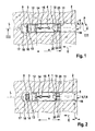
- an inventive expansion anchor 1 is shown.
- the expansion anchor 1 consists of a threaded sleeve 2, a spreader 3 and an expansion sleeve 4.
- the threaded sleeve 2 has at its rear in the direction of insertion E 5 an opening 6 in the form of a blind bore with an internal thread 7, which is for receiving a not shown screw for attaching an object (also not shown) is used.
- a tool seat 8 At the front end of the opening 6 adjoins the internal thread 7, a tool seat 8 for receiving a rotary tool (not shown).
- the tool seat 8 is a hexagon socket for receiving an Allen wrench.
- the expansion element 3 is designed as a cone nut, with a continuous central bore with an internal thread 25, with which the expansion element 3 is screwed onto the external thread 10 of the threaded bolt 9.
- the threaded sleeve 2 and the spreader 3 is rotatably coupled.
- the expansion element 3 can be screwed onto the external thread 10 of the threaded bolt 9 and thus the axial distance a between the threaded sleeve 2 and the expansion element 3 can be shortened.
- axial is meant here in the direction of the longitudinal axis L of the expansion anchor 1.
- the expansion element 3 has a frustoconical expansion section 12, which widens in the direction of insertion E in the radial direction, ie in diameter.
- the expansion section 12 is adjoined by a hollow-cylindrical section as the coating zone 13.
- the spreading portion 12 serves to spread the expansion sleeve 3, which has at its front end by slots 14 separate expansion legs 15.
- the expansion element 3 has at its rear end in the direction of insertion E semicircular cutouts 19 into which the spacer sleeve 11 engages, so that the spacer sleeve 11 and the expansion sleeve 4 are coupled together rotationally fixed.
- the spacer sleeve 11 is a hollow cylindrical sleeve, which consists of two sleeve parts 20, 21, which are connected by a predetermined breaking point 22.
- the front in the direction of insertion E sleeve part 20 has an inner diameter which is substantially equal to the outer diameter of the threaded bolt 9, wherein the outer diameter of the front sleeve part of the 20 is smaller than the outer diameter of the expansion sleeve 4.
- the rear sleeve part 21 has an inner diameter which is larger than the inner diameter of the front sleeve part 20.
- the two sleeve parts 20, 21 are in one piece.
- the predetermined breaking point 22 which connects the two sleeve parts 20, 21, so that the rear sleeve part 21 is pushed over the front sleeve part 20 and the spacer sleeve 11 can thereby be shortened in the axial direction.
- ribs projecting radially beyond the expansion sleeve 4 and the threaded sleeve 2 are arranged as anti-rotation means 23.
- the expansion sleeve 4 is also rotatably held in the borehole 16 by the investment in the borehole wall and on the semi-circular cutouts 19 into which the spacer sleeve 11 engages.
- the expansion sleeve 4 is located on the expansion portion 12 of the expansion element 3, whereby the expansion element 3 is also held against rotation of the threaded sleeve 2.
- an Allen wrench as a turning tool (not shown) is inserted into the hexagon socket of the tool seat 8 and the threaded sleeve 2 and thereby the threaded bolt 9 in the direction of FIG.
- the spacer sleeve 11 is clamped between the expansion sleeve 4 and the threaded sleeve 2 and exposed to an axially acting pressure force, which leads to breakage of the predetermined breaking point 22 between the sleeve parts 20, 21 when a certain value is exceeded.
- a torque with a defined size must be applied to the threaded sleeve 2 via the tool seat 8. After breaking the predetermined breaking point 22 decreases First, the torque that is necessary to rotate the threaded sleeve 2.
- the spacer sleeve 11 could be formed without predetermined breaking point 22 and only be elastically and / or plastically compressed.
- the torque for rotating the threaded sleeve 2 increases continuously until a defined value for the torque is reached, which signals to the user that the assembly process is completed.
- the assembly of the expansion anchor 1 can be done in this case, for example, with a commercial torque wrench.
- the expansion anchor 1 is simple, without the risk that components are lost. The user must also perform no additional assembly steps for mounting the expansion anchor 1 according to the invention, so that a user can safely and quickly mount an item without special tools.
Abstract
Description
Die Erfindung betrifft einen Spreizanker mit den Merkmalen des Oberbegriffs des Anspruchs 1 und ein Verfahren zur Montage des Spreizankers.The invention relates to an expansion anchor with the features of the preamble of
Spreizanker mit Innengewinde zum Befestigen eines Gegenstands an einem Verankerungsgrund mit einer Schraube sind bekannt. Beispielsweise zeigt die Offenlegungsschrift
Aus der europäischen Patentanmeldung
Ausgehend vom bekannten Stand der Technik ist die Aufgabe der Erfindung, einen Spreizanker zu schaffen, der diese Nachteile überwindet.Starting from the known state of the art, the object of the invention is to provide an expansion anchor which overcomes these disadvantages.
Diese Aufgabe wird erfindungsgemäß durch einen Spreizanker mit den Merkmalen des Anspruchs 1 und durch ein Verfahren zur Montage des Spreizankers mit den Merkmalen des Anspruchs 7 gelöst.This object is achieved by an expansion anchor with the features of
Der erfindungsgemäße Spreizanker weist eine Gewindehülse auf, an der in Einbringrichtung hinten ein nach hinten offenes Innengewinde zum Befestigen eines Gegenstands mit einer Schraube angeordnet ist. Mit "Einbringrichtung" ist hier die Richtung gemeint, in die der Spreizanker planmäßig in ein Bohrloch eingeführt wird. Die Gewindehülse kann an ihrem vorderen Ende offen oder geschlossen sein. Das Innengewinde ist insbesondere ein metrisches Gewinde. Zum Verankern des Spreizankers im Verankerungsgrund weist der Spreizanker ein Spreizelement und eine Spreizhülse auf. Die Spreizhülse kann durch das Spreizelement verspreizt, also in radialer Richtung geweitet werden. Die Spreizhülse besteht beispielsweise aus einem in Längsrichtung geschlitzten und in Umfangsrichtung gebogenen Blechstreifen. Das Spreizelement ist insbesondere konisch ausgebildet, sein Durchmesser nimmt in Einbringrichtung beispielsweise kegelartig zu. Insbesondere ist das Spreizelement eine Konusmutter mit kegelstumpfförmigem Abschnitt, die mit der Gewindehülse durch einen Gewindebolzen, der an der Gewindehülse angeordnet ist, drehbar gekoppelt ist. Der Gewindebolzen ist insbesondere einstückig mit der Gewindehülse verbunden. Alternativ kann das Spreizelement einstückig mit dem Gewindebolzen als Konusbolzen ausgeführt sein, der mit einem Außengewinde in ein zweites Innengewinde der Gewindehülse eingreift, das in Einbringrichtung vorne an der Gewindehülse angeordnet ist. Das vordere und das hintere Innengewinde der Gewindehülse können in der Spreizhülse gemeinsam ein durchgehendes Innengewinde bilden. Dadurch, dass die Gewindehülse mit dem Spreizelement durch ein Gewinde drehbar gekoppelt ist, kann der axiale Abstand zwischen der Gewindehülse und dem Spreizelement durch Drehen der Gewindehülse verkürzt werden. Durch das Drehen wird das konische Spreizelement durch das Gewinde in Richtung der Gewindehülse bewegt, dabei in die Spreizhülse eingezogen und die Spreizhülse verspreizt.The expansion anchor according to the invention has a threaded sleeve on which a rearwardly open internal thread for fastening an object is arranged with a screw in the direction of insertion behind. By "insertion direction" is meant here the direction in which the expansion anchor is systematically introduced into a borehole. The Threaded sleeve may be open or closed at its front end. The internal thread is in particular a metric thread. For anchoring the expansion anchor in the anchoring ground, the expansion anchor has an expansion element and an expansion sleeve. The expansion sleeve can be expanded by the expansion element, that is widened in the radial direction. The expansion sleeve consists for example of a longitudinally slotted and bent in the circumferential direction sheet metal strip. The expansion element is in particular conical, its diameter increases in the direction of insertion, for example, conically. In particular, the expansion element is a cone nut with frustoconical portion which is rotatably coupled to the threaded sleeve by a threaded bolt which is arranged on the threaded sleeve. The threaded bolt is in particular integrally connected to the threaded sleeve. Alternatively, the expansion element may be made in one piece with the threaded bolt as a cone bolt, which engages with an external thread in a second internal thread of the threaded sleeve, which is arranged in the insertion direction at the front of the threaded sleeve. The front and the rear internal thread of the threaded sleeve can together form a continuous internal thread in the expansion sleeve. Characterized in that the threaded sleeve is rotatably coupled to the spreader by a thread, the axial distance between the threaded sleeve and the spreader can be shortened by turning the threaded sleeve. By turning the conical expansion element is moved by the thread in the direction of the threaded sleeve, thereby retracted into the expansion sleeve and expands the expansion sleeve.
Erfindungsgemäß ist am Spreizanker in axialer Richtung zwischen der Gewindehülse und der Spreizhülse eine in axialer Richtung verkürzbare Distanzhülse angeordnet. Wird der axiale Abstand zwischen der Gewindehülse und dem Spreizelement durch das Drehen der Gewindehülse verkürzt, so wird die Distanzhülse in axialer Richtung gestaucht und der Abstand zwischen dem hinteren Ende des Spreizankers und dem Spreizelement verkürzt. "Axial" bedeutet hier in Richtung der Längsachse des Spreizankers, wobei sich die Längsachse parallel zur Einbringrichtung des Spreizankers in ein Bohrloch erstreckt. Das Verkürzen der Gewindehülse kann insbesondere durch elastisches und/oder plastisches Verformen und/oder durch teleskopartiges Ineinanderschieben erfolgen.According to the invention, a shortenable in the axial direction spacer sleeve is arranged on the expansion anchor in the axial direction between the threaded sleeve and the expansion sleeve. If the axial distance between the threaded sleeve and the expansion element is shortened by the rotation of the threaded sleeve, the spacer sleeve is compressed in the axial direction and the distance between the rear end of the expansion anchor and the expansion element is shortened. "Axial" means here in the direction of the longitudinal axis of the expansion anchor, wherein the longitudinal axis extends parallel to the direction of insertion of the expansion anchor into a borehole. The shortening of the threaded sleeve can be done in particular by elastic and / or plastic deformation and / or by telescoping telescoping.
Zur Montage des erfindungsgemäßen Spreizankers wird zunächst ein Bohrloch in einem Verankerungsgrund erstellt und der Spreizanker in das Bohrloch so weit eingebracht, bis das in Einbringrichtung hintere Ende des Spreizankers im Wesentlichen bündig mit dem Bohrlochmund ist. Der Spreizanker kann beispielsweise vom Anwender in einfacher Weise mit einem Hammer durch Schläge auf das hintere Ende des Spreizankers eingebracht werden, ohne dass ein spezielles Setzwerkzeug notwendig ist. Der "Bohrlochmund" ist die hintere Öffnung des Bohrlochs, in das der Spreizanker eingebracht wird. Im Regelfall ist der Bohrlochmund an der Oberfläche des Verankerungsgrunds. Wenn sich das Bohrloch allerdings bis in den zu befestigenden Gegenstand erstreckt, beispielsweise wenn der Gegenstand beim Erstellen des Bohrlochs selbst durchbohrt wird, so kann der Bohrlochmund auch an der dem Verankerungsgrund abgewandten Seite des Gegenstands liegen.To assemble the expansion anchor according to the invention, a borehole is first created in an anchoring base and the expansion anchor is inserted into the borehole until the rear end of the expansion anchor, which is in the insertion direction, is substantially flush with the boring hole Borehole mouth is. The expansion anchor can be introduced by the user in a simple manner with a hammer by blows on the rear end of the expansion anchor without a special setting tool is necessary. The "borehole mouth" is the rear opening of the borehole into which the expansion anchor is introduced. As a rule, the borehole mouth is at the surface of the anchoring ground. However, if the borehole extends into the object to be fastened, for example if the object itself is pierced during the construction of the borehole, then the borehole mouth can also lie on the side of the object facing away from the anchoring ground.
Nach dem Einbringen in das Bohrloch liegt die Spreizhülse im Regelfall mit etwas Druck an der Bohrlochwand und am Spreizelement an. Durch die Anlage wirkt zwischen den Teilen eine Reibung, so dass die Bohrlochwand, die Spreizhülse und das Spreizelement gegeneinander im Wesentlichen drehfest sind. Die Spreizhülse stützt sich über die Distanzhülse an der Gewindehülse ab. Wird die Gewindehülse gegenüber dem Spreizelement gedreht, so verkürzt sich der axiale Abstand zwischen der Gewindehülse und dem Spreizelement, beispielsweise indem ein als Konusmutter ausgebildetes Spreizelement auf einen an der Gewindehülse angeordneten Gewindebolzen aufgeschraubt wird. Durch das Aufschrauben wird das Spreizelement in die Spreizhülse eingezogen und die Spreizhülse in radialer Richtung aufgespreizt. Durch das Aufspreizen wird die Reibung zwischen der Spreizhülse und der Bohrlochwand so stark erhöht, dass die Spreizhülse im Bohrloch ortsfest ist. Durch weiteres Drehen der Gewindehülse wird der Abstand zwischen der Gewindehülse und dem Spreizelement weiter verkürzt, wobei die Distanzhülse in axialer Richtung verkürzt und die Gewindehülse in das Bohrloch eingezogen wird, so dass sie unter dem Bohrlochmund untersteht. Bei weiterem Drehen der Gewindehülse erhöht sich das Drehmoment, das zum Verkürzen des axialen Abstands zwischen der Spreizhülse und der Gewindehülse auf die Gewindehülse aufgebracht werden muss. Beim Erreichen eines definierten Drehmoments weiß der Anwender, dass die Distanzhülse um ein bestimmtes Maß verkürzt und der gewünschte Unterstand erreicht ist. Das Aufspreizen der Spreizhülse und das Verkürzen der Distanzhülse sind zwei Schritte, die insbesondere nacheinander erfolgen. Ohne den Erfindungsgedanken zu verlassen, können sich die Schritte aber auch überschneiden.After insertion into the borehole, the expansion sleeve is normally applied with some pressure to the borehole wall and to the expansion element. By the system acts between the parts a friction, so that the borehole wall, the expansion sleeve and the expansion element against each other are substantially rotationally fixed. The expansion sleeve is supported on the spacer sleeve on the threaded sleeve. If the threaded sleeve is rotated relative to the expansion element, then the axial distance between the threaded sleeve and the expansion element is shortened, for example by a spreading element designed as a cone nut being screwed onto a threaded bolt arranged on the threaded sleeve. By screwing the spreader is retracted into the expansion sleeve and the expansion sleeve spread in the radial direction. Due to the spreading, the friction between the expansion sleeve and the borehole wall is increased so much that the expansion sleeve is stationary in the borehole. By further rotation of the threaded sleeve, the distance between the threaded sleeve and the expansion element is further shortened, wherein the spacer sleeve is shortened in the axial direction and the threaded sleeve is drawn into the borehole, so that it is subordinate to the borehole mouth. Upon further rotation of the threaded sleeve, the torque increases, which must be applied to shorten the axial distance between the expansion sleeve and the threaded sleeve on the threaded sleeve. When reaching a defined torque, the user knows that the distance sleeve is shortened by a certain amount and the desired shelter is reached. The spreading of the expansion sleeve and the shortening of the spacer sleeve are two steps that take place in particular successively. Without departing from the spirit of the invention, however, the steps may also overlap.
Allein durch den Aufbau des erfindungsgemäßen Spreizankers wird erreicht, dass beim Montieren des Spreizankers planmäßig ein vorgesehener Unterstand erreicht wird, ohne dass der Anwender ein spezielles Werkzeug oder zusätzliche Bauteile am Spreizanker benötigt, die auf einer Baustelle leicht verloren gehen können. Auch ist kein zusätzlicher Montageschritt notwendig. Die Distanzhülse ist als integraler Bestandteil verliersicher zwischen der Spreizhülse und der Gewindehülse am Spreizanker angeordnet, was die Montagesicherheit erhöht.The design of the expansion anchor according to the invention alone achieves the result that, when the expansion anchor is mounted, a planned shelter is achieved on schedule, without that the user needs a special tool or additional components on the expansion anchor that can easily be lost on a construction site. Also, no additional assembly step is necessary. The spacer sleeve is arranged as an integral part captive between the expansion sleeve and the threaded sleeve on the expansion anchor, which increases the mounting security.
Vorzugsweise umfasst die Distanzhülse zwei Hülsenteile, die über eine Sollbruchstelle miteinander verbunden sind. Wird bei der Montage des Spreizankers die Distanzhülse in axialer Richtung verkürzt, so bricht die Distanzhülse an der Sollbruchstelle. Durch den Bruch der Sollbruchstelle entstehen aus der Distanzhülse mindestens zwei Hülsenteile, die insbesondere teleskopartig ineinanderschiebbar sind. Die Sollbruchstelle kann beispielsweise so ausgelegt sein, dass der Bruch dann erfolgt, wenn zum Drehen der Gewindehülse ein bestimmtes Drehmoment notwendig ist. Die Größe des zum Bruch der Sollbruchstelle notwendigen Drehmoments kann beispielsweise zur Größe des Drehmoments korrespondieren, das zum planmäßigen Verspreizen der Spreizhülse notwendig ist: Erst wenn die Spreizhülse planmäßig im Bohrloch verspreizt ist, bricht die Sollbruchstelle. Nach dem Bruch werden die beiden Hülsenteile durch weiteres Drehen ineinander geschoben, wofür insbesondere ein kleineres Drehmoment notwendig ist, als zum Bruch der Sollbruchstelle, so dass nach dem Bruch der Sollbruchstelle das zum Drehen notwendige Drehmoment spürbar abfällt. Die Distanzhülse wird durch das weitere Drehen verkürzt und die Gewindehülse weiter in das Bohrloch eingeschoben, da die Spreizhülse verspreizt und im Bohrloch ortsfest ist. Der Anwender hat somit eine direkte Kontrolle der ordnungsgemäßen Verspreizung der Spreizhülse. Die Distanzhülse kann so ausgebildet sein, dass sie einen Anschlag aufweist, an dem mindestens eines der beiden Hülsenteile ansteht, wenn die beiden Hülsenteile um eine vorgegebene Strecke ineinander geschoben wurden. Diese Strecke entspricht beispielsweise im Wesentlichen dem gewünschten Unterstand. Steht ein Hülsenteil am Anschlag an, so erhöht sich das zum weiteren Drehen der Gewindehülse auf die Gewindehülse aufzubringende Drehmoment merklich, was einem Anwender signalisiert, dass der gewünschte Unterstand erreicht und der Spreizanker ordnungsgemäß verspreizt ist. Die Montage des Spreizankers ist beendet.Preferably, the spacer sleeve comprises two sleeve parts which are interconnected via a predetermined breaking point. If the spacer sleeve is shortened in the axial direction during assembly of the expansion anchor, the spacer sleeve breaks at the predetermined breaking point. Due to the breakage of the predetermined breaking point, at least two sleeve parts, which in particular telescope one another, arise from the spacer sleeve. The predetermined breaking point can for example be designed so that the break occurs when a certain torque is necessary to rotate the threaded sleeve. The size of the torque required to break the predetermined breaking point can correspond, for example, to the magnitude of the torque required for the planned spreading of the expansion sleeve: only when the expansion sleeve is intentionally spread in the borehole does the predetermined breaking point break. After breakage, the two sleeve parts are pushed into each other by further rotation, for which in particular a smaller torque is necessary, as to break the predetermined breaking point, so that after breaking the predetermined breaking point, the torque necessary for turning drops noticeably. The spacer sleeve is shortened by the further rotation and the threaded sleeve inserted further into the borehole, since the expansion sleeve is braced and fixed in the borehole. The user thus has a direct control of the proper spreading of the expansion sleeve. The spacer sleeve may be formed so that it has a stop on which at least one of the two sleeve parts is present when the two sleeve parts have been pushed into each other by a predetermined distance. For example, this route essentially corresponds to the desired shelter. If a sleeve part abuts against the stop, then the torque to be applied to the threaded sleeve for further rotation of the threaded sleeve increases noticeably, which signals to a user that the desired shelter has been reached and the expansion anchor has been properly braced. The assembly of the expansion anchor is completed.
Um mit einem Drehwerkzeug, beispielsweise einem Schraubendreher oder einem Inbusschlüssel, ein Drehmoment auf die Gewindehülse übertragen zu können, ist in einer Ausführungsform des erfindungsgemäßen Spreizankers an der Gewindehülse ein Werkzeugsitz angeordnet. Der Werkzeugsitz ist beispielsweise als Innensechskant ausgeführt. Vorzugsweise ist der Werkzeugsitz in der Gewindehülse angeordnet, was einen guten Sitz des Drehwerkzeugs gewährleistet und beispielsweise ein Abrutschen des Drehwerkzeugs vom Spreizanker verhindert. Beispielsweise ist die Gewindehülse an ihrem vorderen Ende geschlossen und der Werkzeugsitz ist vor dem Innengewinde, am Boden der Öffnung des Innengewindes, angeordnet.In order to be able to transmit torque to the threaded sleeve with a rotary tool, for example a screwdriver or an Allen key, a tool seat is arranged on the threaded sleeve in one embodiment of the expansion anchor according to the invention. The tool seat is, for example, as a hexagon socket executed. Preferably, the tool seat is arranged in the threaded sleeve, which ensures a good fit of the rotary tool and, for example, prevents slipping of the rotary tool from the expansion anchor. For example, the threaded sleeve is closed at its front end and the tool seat is arranged in front of the internal thread, at the bottom of the opening of the internal thread.
Weiterhin ist bevorzugt, dass an der Distanzhülse ein Drehsicherungsmittel angeordnet ist. Das Drehsicherungsmittel verhindert im Bohrloch, dass die Distanzhülse beim Drehen der Gewindehülse mitdreht. Beispielsweise ist das Drehsicherungsmittel als radial über die Gewindehülse vorstehende Rippe, als vorspringender Zapfen oder als elastischer Flügel ausgeführt. Weiterhin ist bevorzugt, dass die Distanzhülse und die Spreizhülse miteinander drehfest gekoppelt sind. Die drehfeste Kopplung der Distanzhülse mit der Spreizhülse hat insbesondere den Vorteil, dass, wenn der Spreizanker im Bohrloch eingebracht ist, die Distanzhülse mit ihrem Drehsicherungsmittel ein Mitdrehen der Spreizhülse beim Drehen der Gewindehülse verhindert, falls die Reibung zwischen der Bohrlochwand und der Spreizhülse dafür zu gering ist.Furthermore, it is preferred that an anti-rotation means is arranged on the spacer sleeve. The anti-rotation means prevents in the borehole that the spacer sleeve rotates when turning the threaded sleeve. For example, the anti-rotation means is designed as a radially projecting rib over the threaded sleeve, as a projecting pin or as an elastic wing. Furthermore, it is preferred that the spacer sleeve and the expansion sleeve are coupled together rotationally fixed. The non-rotatable coupling of the spacer sleeve with the expansion sleeve has the particular advantage that when the expansion anchor is introduced in the borehole, the spacer sleeve with its anti-rotation means co-rotation of the expansion sleeve when turning the threaded sleeve prevents if the friction between the borehole wall and the expansion sleeve for it too low is.
Die Erfindung wird nachfolgend anhand eines in den Figuren dargestellten Ausführungsbeispiels näher beschrieben.The invention will be described in more detail with reference to an embodiment shown in FIGS.
Es zeigen:
Figur 1- einen unverspreizten erfindungsgemäßen Spreizanker nach dem Einbringen in ein Bohrloch in einer Seitenansicht;
Figur 2- den erfindungsgemäßen Spreizanker nach Abschluss der Montage in dem Bohrloch in einer Seitenansicht; und
Figur 3- einen Längsschnitt durch den unverspreizten erfindungsgemäßen Spreizanker.
- FIG. 1
- an unexpanded expansion anchor according to the invention after introduction into a borehole in a side view;
- FIG. 2
- the expansion anchor according to the invention after completion of the assembly in the wellbore in a side view; and
- FIG. 3
- a longitudinal section through the unexpanded expansion anchor according to the invention.
In den Figuren ist ein erfindungsgemäßer Spreizanker 1 dargestellt. Der Spreizanker 1 besteht aus einer Gewindehülse 2, einem Spreizelement 3 und einer Spreizhülse 4. Die Gewindehülse 2 weist an ihrem in Einbringrichtung E hinteren Ende 5 eine Öffnung 6 in Form einer Sacklochbohrung mit einem Innengewinde 7 auf, das zur Aufnahme einer nicht dargestellten Schraube zum Befestigen eines Gegenstands (ebenfalls nicht dargestellt) dient. Am vorderen Ende der Öffnung 6 schließt sich an das Innengewinde 7 ein Werkzeugsitz 8 zur Aufnahme eines Drehwerkzeugs (nicht dargestellt) an. Bei dem Werkzeugsitz 8 handelt es sich um einen Innensechskant zur Aufnahme eines Inbusschlüssels. An die Gewindehülse 2 schließt sich in Einbringrichtung E ein gegenüber der Gewindehülse 2 im Durchmesser reduzierter Gewindebolzen 9 mit einem Außengewinde 10 an, der mit der Gewindehülse 2 einstückig ist. Auf den Gewindebolzen 9 ist eine verkürzbare Distanzhülse 11 und die Spreizhülse 4 aufgeschoben, die den Gewindebolzen 9 in Umfangsrichtung umfassen. In Einbringrichtung E vor der Spreizhülse 4 und der Distanzhülse 11 ist das Spreizelement 3 angeordnet, das die beiden Hülsen 4, 11 auf dem Gewindebolzen 9 hält.In the figures, an
Das Spreizelement 3 ist als Konusmutter ausgebildet, mit einer durchgehenden zentrischen Bohrung mit einem Innengewinde 25, mit dem das Spreizelement 3 auf das Außengewinde 10 des Gewindebolzens 9 aufgeschraubt ist. Über den Gewindebolzen 9 ist die Gewindehülse 2 und das Spreizelement 3 drehbar gekoppelt. Durch Drehen der Gewindehülse 2 kann das Spreizelement 3 auf das Außengewinde 10 des Gewindebolzen 9 aufgeschraubt und somit der axiale Abstand a zwischen der Gewindehülse 2 und dem Spreizelement 3 verkürzt werden. Mit "axial" ist hier in Richtung der Längsachse L des Spreizankers 1 gemeint. Das Spreizelement 3 weist einen kegelstumpfförmigen Spreizabschnitt 12 auf, der sich in Einbringrichtung E in radialer Richtung, also im Durchmesser, erweitert. An den Spreizabschnitt 12 schließt sich ein hohlzylindrischer Abschnitt als Überzugszone 13 an. Der Spreizabschnitt 12 dient zum Aufspreizen der Spreizhülse 3, die an ihrem vorderen Ende durch Schlitze 14 voneinander getrennte Spreizschenkel 15 aufweist. Durch das Aufschrauben des Spreizelements 3 auf den Gewindebolzen 9 wird das Spreizelement 3 zwischen die Spreizschenkel 15 in die Spreizhülse 4 geschoben, wodurch die Spreizschenkel 15 der Spreizhülse 4 radial nach außen aufgespreizt werden. Das Spreizelement 3 weist an seinem in Einbringrichtung E hinteren Ende halbkreisförmige Ausschnitte 19 auf, in die die Distanzhülse 11 eingreift, so dass die Distanzhülse 11 und die Spreizhülse 4 miteinander drehfest gekoppelt sind.The
Die Distanzhülse 11 ist eine hohlzylindrische Hülse, die aus zwei Hülsenteilen 20, 21 besteht, die durch eine Sollbruchstelle 22 verbunden sind. Der in Einbringrichtung E vordere Hülsenteil 20 weist einen Innendurchmesser auf, der im Wesentlichen gleich dem Außendurchmesser des Gewindebolzens 9 ist, wobei der Außendurchmesser des vorderen Hülsenteil des 20 kleiner als der Außendurchmesser der Spreizhülse 4 ist. Der hintere Hülsenteil 21 weist dagegen einen Innendurchmesser auf, der größer ist, als der Innendurchmesser des vorderen Hülsenteils 20. Die beiden Hülsenteile 20, 21 sind einstückig. Wird die Distanzhülse 11 gestaucht, so bricht die Sollbruchstelle 22, die die beiden Hülsenteile 20, 21 verbindet, so dass der hintere Hülsenteil 21 über den vorderen Hülsenteil 20 geschoben und die Distanzhülse 11 dadurch in axialer Richtung verkürzt werden kann. Am hinteren Hülsenteil 21 sind radial über die Spreizhülse 4 und die Gewindehülse 2 überstehende Rippen als Drehsicherungsmittel 23 angeordnet.The
Ist der Spreizanker 1, wie in
Durch weiteres Drehen der Gewindehülse 2 wird die Distanzhülse 11 zwischen der Spreizhülse 4 und der Gewindehülse 2 verspannt und einer axial wirkenden Druckkraft ausgesetzt, die beim Überschreiten eines bestimmten Wertes zum Bruch der Sollbruchstelle 22 zwischen den Hülsenteilen 20, 21 führt. Zum Erreichen der Kraft muss über den Werkzeugsitz 8 auf die Gewindehülse 2 ein Drehmoment mit einer definierten Größe aufgebracht werden. Nach dem Bruch der Sollbruchstelle 22 verringert sich zunächst das Drehmoment, das zum Drehen der Gewindehülse 2 notwendig ist. Durch weiteres Drehen der Gewindehülse 2 gegenüber dem orts- und drehfesten Spreizelement 3 wird der hintere Hülsenteil 21 über den vorderen Hülsenteil 20 geschoben, wodurch die Distanzhülse 11 in axialer Richtung verkürzt und die Gewindehülse 2 in Richtung der Einbringrichtung E in das Bohrloch16 bewegt wird, so dass ein Unterstand u entsteht, wie dies
Alternativ könnte die Distanzhülse 11 auch ohne Sollbruchstelle 22 ausgebildet sein und nur elastisch und/oder plastisch gestaucht werden. Beim Verkürzen durch elastisches und/oder plastisches Stauchen vergrößert sich das Drehmoment zum Drehen der Gewindehülse 2 kontinuierlich, bis ein definierter Wert für das Drehmoment erreicht ist, der dem Anwender signalisiert, dass der Montagevorgang beendet ist. Die Montage des Spreizankers 1 kann in diesem Fall beispielsweise mit einem handelüblichen Drehmomentschlüssel erfolgen.Alternatively, the
Der Spreizanker 1 ist einfach aufgebaut, ohne dass die Gefahr besteht, dass Bauteile verloren gehen. Der Anwender muss zur Montage des erfindungsgemäßen Spreizankers 1 zudem keine zusätzlichen Montageschritte ausführen, so dass ein Anwender einen Gegenstand sicher und schnell ohne Spezialwerkzeug montieren kann.The
- 11
- Spreizankerexpansion anchor
- 22
- Gewindehülsethreaded sleeve
- 33
- Spreizelementspreader
- 44
- Spreizhülseexpansion sleeve
- 55
-
hinteres Ende der Spreizankers 1Rear end of the
expansion anchor 1 - 66
- Öffnungopening
- 77
- Innengewindeinner thread
- 88th
- Werkzeugsitztool seat
- 99
- Gewindebolzenthreaded bolt
- 1010
- Außengewindeexternal thread
- 1111
- DistanzhülseStand Off
- 1212
- Spreizabschnittspreading
- 1313
- Überzugszonecoating zone
- 1414
- Schlitzslot
- 1515
- Spreizschenkelexpansion limbs
- 1616
- Bohrlochwell
- 1717
- Verankerungsgrundanchorage ground
- 1818
- Bohrlochmundborehole mouth
- 1919
- halbkreisförmiger Ausschnittsemicircular cutout
- 2020
- vorderer Hülsenteilfront sleeve part
- 2121
- hinterer Hülsenteilrear sleeve part
- 2222
- SollbruchstelleBreaking point
- 2323
- DrehsicherungsmittelRotation means
- 2424
- Anschlagflächestop surface
- 2525
-
Innengewinde des Spreizelements 3Internal thread of the
expansion element 3 - aa
-
axialer Abstand zwischen der Gewindehülse 2 und dem Spreizelement 3axial distance between the threaded
sleeve 2 and the expansion element. 3 - Ee
- Einbringrichtungof introduction
- LL
- Längsachselongitudinal axis
- PP
- Drehrichtungdirection of rotation
- uu
- Unterstandshelter
Claims (11)
wobei die Gewindehülse (2) in Einbringrichtung (E) hinten ein Innengewinde (7) zum Befestigen eines Gegenstandes mit einer Schraube aufweist, und
wobei die Gewindehülse (2) mit dem Spreizelement (3) drehbar gekoppelt ist, so dass durch Drehen der Gewindehülse (2) der axiale Abstand (a) zwischen der Gewindehülse (2) und dem Spreizelement (3) verkürzbar ist,
wodurch die Spreizhülse (4) durch das Spreizelement (3) in radialer Richtung aufgespreizt wird,
dadurch gekennzeichnet,
dass in axialer Richtung zwischen der Gewindehülse (2) und der Spreizhülse (4) eine in axialer Richtung verkürzbare Distanzhülse (11) angeordnet ist.Expansion anchor (1) with a threaded sleeve (2), an expansion element (3) and an expansion sleeve (4),
wherein the threaded sleeve (2) in the insertion direction (E) at the rear has an internal thread (7) for fastening an object with a screw, and
wherein the threaded sleeve (2) is rotatably coupled to the expansion element (3) so that the axial distance (a) between the threaded sleeve (2) and the expansion element (3) can be shortened by turning the threaded sleeve (2),
whereby the expansion sleeve (4) is spread in the radial direction by the expansion element (3),
characterized,
that in the axial direction between the threaded sleeve (2) and the expansion sleeve (4) a shortened in the axial direction spacer sleeve (11) is arranged.
Priority Applications (1)
| Application Number | Priority Date | Filing Date | Title |
|---|---|---|---|
| PL12401246T PL2604869T3 (en) | 2011-12-13 | 2012-12-11 | Expansion anchor and method for mounting the expansion anchor |
Applications Claiming Priority (2)
| Application Number | Priority Date | Filing Date | Title |
|---|---|---|---|
| DE102011056312 | 2011-12-13 | ||
| DE201210110688 DE102012110688A1 (en) | 2011-12-13 | 2012-11-08 | Expansion anchor and method for mounting the expansion anchor |
Publications (2)
| Publication Number | Publication Date |
|---|---|
| EP2604869A1 true EP2604869A1 (en) | 2013-06-19 |
| EP2604869B1 EP2604869B1 (en) | 2018-08-29 |
Family
ID=47504757
Family Applications (1)
| Application Number | Title | Priority Date | Filing Date |
|---|---|---|---|
| EP12401246.9A Active EP2604869B1 (en) | 2011-12-13 | 2012-12-11 | Expansion anchor and method for mounting the expansion anchor |
Country Status (6)
| Country | Link |
|---|---|
| EP (1) | EP2604869B1 (en) |
| CN (1) | CN103161806B (en) |
| DE (1) | DE102012110688A1 (en) |
| ES (1) | ES2695552T3 (en) |
| PL (1) | PL2604869T3 (en) |
| TR (1) | TR201812975T4 (en) |
Cited By (3)
| Publication number | Priority date | Publication date | Assignee | Title |
|---|---|---|---|---|
| CN105864253A (en) * | 2016-06-07 | 2016-08-17 | 杭州斯泰新材料技术有限公司 | Punching and chamfering synchronous double-reaming anchor bolt and mounting structure on concrete |
| CN105864252A (en) * | 2016-06-07 | 2016-08-17 | 杭州斯泰新材料技术有限公司 | Lock type anchor bolt and installation structure on concrete |
| EP3315795A1 (en) * | 2016-10-25 | 2018-05-02 | fischerwerke GmbH & Co. KG | Expansion anchor |
Families Citing this family (7)
| Publication number | Priority date | Publication date | Assignee | Title |
|---|---|---|---|---|
| EP2848826A1 (en) * | 2013-09-16 | 2015-03-18 | HILTI Aktiengesellschaft | Split anchor |
| DE102016110162A1 (en) * | 2015-07-15 | 2017-01-19 | Fischerwerke Gmbh & Co. Kg | Self-cutting undercut anchor |
| DE102016103196A1 (en) * | 2015-07-22 | 2017-01-26 | Fischerwerke Gmbh & Co. Kg | Fastening arrangement and expansion anchor |
| CN106351926B (en) * | 2016-09-19 | 2018-12-14 | 浙江亦宸五金有限公司 | A kind of expansion bolt of anti-rotation |
| DE102017121232A1 (en) * | 2016-10-25 | 2018-04-26 | Fischerwerke Gmbh & Co. Kg | expansion anchor |
| CN109630525A (en) * | 2019-01-21 | 2019-04-16 | 刘韦明 | Compound expansion connector |
| CN110219864A (en) * | 2019-06-06 | 2019-09-10 | 法施达科技有限公司 | A kind of expansion anchor that anti-tube expansion falls off |
Citations (5)
| Publication number | Priority date | Publication date | Assignee | Title |
|---|---|---|---|---|
| GB1453435A (en) * | 1972-10-27 | 1976-10-20 | Harris Ltd Edgar | Expander device |
| DE3712213A1 (en) | 1987-04-10 | 1988-10-27 | Fischer Artur Werke Gmbh | FASTENING ELEMENT |
| DE9310356U1 (en) * | 1993-07-12 | 1993-09-23 | Mea Meisinger Stahl & Kunststo | SPREADING DOWEL |
| EP0741250A1 (en) | 1995-05-03 | 1996-11-06 | The Rawlplug Company Limited | Fasteners |
| EP1211430A2 (en) * | 2000-11-29 | 2002-06-05 | Societe De Prospection Et D'inventions Techniques Spit | Expansion dowel with a compressible portion |
-
2012
- 2012-11-08 DE DE201210110688 patent/DE102012110688A1/en not_active Withdrawn
- 2012-12-11 PL PL12401246T patent/PL2604869T3/en unknown
- 2012-12-11 TR TR2018/12975T patent/TR201812975T4/en unknown
- 2012-12-11 ES ES12401246T patent/ES2695552T3/en active Active
- 2012-12-11 EP EP12401246.9A patent/EP2604869B1/en active Active
- 2012-12-13 CN CN201210538244.6A patent/CN103161806B/en active Active
Patent Citations (5)
| Publication number | Priority date | Publication date | Assignee | Title |
|---|---|---|---|---|
| GB1453435A (en) * | 1972-10-27 | 1976-10-20 | Harris Ltd Edgar | Expander device |
| DE3712213A1 (en) | 1987-04-10 | 1988-10-27 | Fischer Artur Werke Gmbh | FASTENING ELEMENT |
| DE9310356U1 (en) * | 1993-07-12 | 1993-09-23 | Mea Meisinger Stahl & Kunststo | SPREADING DOWEL |
| EP0741250A1 (en) | 1995-05-03 | 1996-11-06 | The Rawlplug Company Limited | Fasteners |
| EP1211430A2 (en) * | 2000-11-29 | 2002-06-05 | Societe De Prospection Et D'inventions Techniques Spit | Expansion dowel with a compressible portion |
Cited By (5)
| Publication number | Priority date | Publication date | Assignee | Title |
|---|---|---|---|---|
| CN105864253A (en) * | 2016-06-07 | 2016-08-17 | 杭州斯泰新材料技术有限公司 | Punching and chamfering synchronous double-reaming anchor bolt and mounting structure on concrete |
| CN105864252A (en) * | 2016-06-07 | 2016-08-17 | 杭州斯泰新材料技术有限公司 | Lock type anchor bolt and installation structure on concrete |
| CN105864253B (en) * | 2016-06-07 | 2019-02-05 | 杭州斯泰新材料技术有限公司 | A kind of dig synchronizes double expansion formula anchor bolts and the mounting structure on concrete |
| CN105864252B (en) * | 2016-06-07 | 2019-02-05 | 杭州斯泰新材料技术有限公司 | A kind of locking-type anchor bolt and the mounting structure on concrete |
| EP3315795A1 (en) * | 2016-10-25 | 2018-05-02 | fischerwerke GmbH & Co. KG | Expansion anchor |
Also Published As
| Publication number | Publication date |
|---|---|
| PL2604869T3 (en) | 2019-02-28 |
| ES2695552T3 (en) | 2019-01-09 |
| DE102012110688A1 (en) | 2013-06-13 |
| EP2604869B1 (en) | 2018-08-29 |
| CN103161806A (en) | 2013-06-19 |
| TR201812975T4 (en) | 2018-09-21 |
| CN103161806B (en) | 2015-05-13 |
Similar Documents
| Publication | Publication Date | Title |
|---|---|---|
| EP2604869B1 (en) | Expansion anchor and method for mounting the expansion anchor | |
| DE602005000797T2 (en) | Element for attaching accessories to metal windows and metal doors | |
| EP2514979B1 (en) | expansion anchor | |
| EP2134976B1 (en) | Anchor and anchor nut thereof | |
| DE102010016797A1 (en) | expansion anchor | |
| DE102005051243A1 (en) | Fastening element for fastening in a through hole in a plate with one-sided accessibility, setting tool and removal tool for the fastening element | |
| EP3074645B1 (en) | Expansion anchor with swelling element for sleeve fixing | |
| DE2547634A1 (en) | SAFETY DOWEL | |
| EP3330550A1 (en) | Method for setting an anchor in an anchor hole in an anchoring base and anchor for setting using the method | |
| EP0993556B1 (en) | Expansion anchor | |
| EP2119919B1 (en) | Mounting assembly | |
| EP2112383A2 (en) | Fastening element | |
| WO2014114432A1 (en) | Securing element | |
| DE19712174C2 (en) | Extraction tool for an expansion anchor | |
| DE102011051618A1 (en) | Expansion anchor for anchoring in borehole of e.g. stone, has threaded shaft threaded into internal thread of expansion body by expansion sleeve, and connector passing through sleeve, where expansion body expands into sleeve | |
| EP2068010A2 (en) | Anchor and anchor assembly tool | |
| DE102011001944A1 (en) | Screw of spreading dowel for fixing insulation board, has tool receiving element which is arranged in rear receiving opening provided with tool holder, and is connected with head by breaking points in rotationally fixed manner | |
| EP2207975B1 (en) | Fixing element | |
| EP1743102A1 (en) | Impact anchor | |
| DE102013103429A1 (en) | insulation holders | |
| EP2527666B1 (en) | Split anchor | |
| DE102011001557A1 (en) | Expansion anchor for fastening fixture to base portion, has internal thread for mounting attachment to base and shaft, in which bore is arranged with internal threads, where expansion anchor has expansion area | |
| EP3322904B1 (en) | Method for establishing a connection | |
| EP2305898B1 (en) | Fastening device for a sanitary object and method for fastening a sanitary object | |
| DE19720033A1 (en) | Masonry plug for screw fitting into porous wall |
Legal Events
| Date | Code | Title | Description |
|---|---|---|---|
| PUAI | Public reference made under article 153(3) epc to a published international application that has entered the european phase |
Free format text: ORIGINAL CODE: 0009012 |
|
| AK | Designated contracting states |
Kind code of ref document: A1 Designated state(s): AL AT BE BG CH CY CZ DE DK EE ES FI FR GB GR HR HU IE IS IT LI LT LU LV MC MK MT NL NO PL PT RO RS SE SI SK SM TR |
|
| AX | Request for extension of the european patent |
Extension state: BA ME |
|
| 17P | Request for examination filed |
Effective date: 20131203 |
|
| RBV | Designated contracting states (corrected) |
Designated state(s): AL AT BE BG CH CY CZ DE DK EE ES FI FR GB GR HR HU IE IS IT LI LT LU LV MC MK MT NL NO PL PT RO RS SE SI SK SM TR |
|
| RAP1 | Party data changed (applicant data changed or rights of an application transferred) |
Owner name: FISCHERWERKE GMBH & CO. KG |
|
| 17Q | First examination report despatched |
Effective date: 20161214 |
|
| GRAP | Despatch of communication of intention to grant a patent |
Free format text: ORIGINAL CODE: EPIDOSNIGR1 |
|
| INTG | Intention to grant announced |
Effective date: 20180419 |
|
| GRAS | Grant fee paid |
Free format text: ORIGINAL CODE: EPIDOSNIGR3 |
|
| GRAA | (expected) grant |
Free format text: ORIGINAL CODE: 0009210 |
|
| AK | Designated contracting states |
Kind code of ref document: B1 Designated state(s): AL AT BE BG CH CY CZ DE DK EE ES FI FR GB GR HR HU IE IS IT LI LT LU LV MC MK MT NL NO PL PT RO RS SE SI SK SM TR |
|
| REG | Reference to a national code |
Ref country code: GB Ref legal event code: FG4D Free format text: NOT ENGLISH |
|
| REG | Reference to a national code |
Ref country code: CH Ref legal event code: EP |
|
| REG | Reference to a national code |
Ref country code: AT Ref legal event code: REF Ref document number: 1035470 Country of ref document: AT Kind code of ref document: T Effective date: 20180915 |
|
| REG | Reference to a national code |
Ref country code: SE Ref legal event code: TRGR |
|
| REG | Reference to a national code |
Ref country code: IE Ref legal event code: FG4D Free format text: LANGUAGE OF EP DOCUMENT: GERMAN |
|
| REG | Reference to a national code |
Ref country code: DE Ref legal event code: R096 Ref document number: 502012013328 Country of ref document: DE |
|
| REG | Reference to a national code |
Ref country code: NL Ref legal event code: FP |
|
| REG | Reference to a national code |
Ref country code: ES Ref legal event code: FG2A Ref document number: 2695552 Country of ref document: ES Kind code of ref document: T3 Effective date: 20190109 |
|
| REG | Reference to a national code |
Ref country code: LT Ref legal event code: MG4D |
|
| PG25 | Lapsed in a contracting state [announced via postgrant information from national office to epo] |
Ref country code: FI Free format text: LAPSE BECAUSE OF FAILURE TO SUBMIT A TRANSLATION OF THE DESCRIPTION OR TO PAY THE FEE WITHIN THE PRESCRIBED TIME-LIMIT Effective date: 20180829 Ref country code: GR Free format text: LAPSE BECAUSE OF FAILURE TO SUBMIT A TRANSLATION OF THE DESCRIPTION OR TO PAY THE FEE WITHIN THE PRESCRIBED TIME-LIMIT Effective date: 20181130 Ref country code: LT Free format text: LAPSE BECAUSE OF FAILURE TO SUBMIT A TRANSLATION OF THE DESCRIPTION OR TO PAY THE FEE WITHIN THE PRESCRIBED TIME-LIMIT Effective date: 20180829 Ref country code: RS Free format text: LAPSE BECAUSE OF FAILURE TO SUBMIT A TRANSLATION OF THE DESCRIPTION OR TO PAY THE FEE WITHIN THE PRESCRIBED TIME-LIMIT Effective date: 20180829 Ref country code: IS Free format text: LAPSE BECAUSE OF FAILURE TO SUBMIT A TRANSLATION OF THE DESCRIPTION OR TO PAY THE FEE WITHIN THE PRESCRIBED TIME-LIMIT Effective date: 20181229 Ref country code: NO Free format text: LAPSE BECAUSE OF FAILURE TO SUBMIT A TRANSLATION OF THE DESCRIPTION OR TO PAY THE FEE WITHIN THE PRESCRIBED TIME-LIMIT Effective date: 20181129 Ref country code: BG Free format text: LAPSE BECAUSE OF FAILURE TO SUBMIT A TRANSLATION OF THE DESCRIPTION OR TO PAY THE FEE WITHIN THE PRESCRIBED TIME-LIMIT Effective date: 20181129 |
|
| PG25 | Lapsed in a contracting state [announced via postgrant information from national office to epo] |
Ref country code: HR Free format text: LAPSE BECAUSE OF FAILURE TO SUBMIT A TRANSLATION OF THE DESCRIPTION OR TO PAY THE FEE WITHIN THE PRESCRIBED TIME-LIMIT Effective date: 20180829 Ref country code: AL Free format text: LAPSE BECAUSE OF FAILURE TO SUBMIT A TRANSLATION OF THE DESCRIPTION OR TO PAY THE FEE WITHIN THE PRESCRIBED TIME-LIMIT Effective date: 20180829 Ref country code: LV Free format text: LAPSE BECAUSE OF FAILURE TO SUBMIT A TRANSLATION OF THE DESCRIPTION OR TO PAY THE FEE WITHIN THE PRESCRIBED TIME-LIMIT Effective date: 20180829 |
|
| PG25 | Lapsed in a contracting state [announced via postgrant information from national office to epo] |
Ref country code: CZ Free format text: LAPSE BECAUSE OF FAILURE TO SUBMIT A TRANSLATION OF THE DESCRIPTION OR TO PAY THE FEE WITHIN THE PRESCRIBED TIME-LIMIT Effective date: 20180829 Ref country code: EE Free format text: LAPSE BECAUSE OF FAILURE TO SUBMIT A TRANSLATION OF THE DESCRIPTION OR TO PAY THE FEE WITHIN THE PRESCRIBED TIME-LIMIT Effective date: 20180829 Ref country code: RO Free format text: LAPSE BECAUSE OF FAILURE TO SUBMIT A TRANSLATION OF THE DESCRIPTION OR TO PAY THE FEE WITHIN THE PRESCRIBED TIME-LIMIT Effective date: 20180829 |
|
| PGFP | Annual fee paid to national office [announced via postgrant information from national office to epo] |
Ref country code: ES Payment date: 20190124 Year of fee payment: 7 |
|
| PG25 | Lapsed in a contracting state [announced via postgrant information from national office to epo] |
Ref country code: DK Free format text: LAPSE BECAUSE OF FAILURE TO SUBMIT A TRANSLATION OF THE DESCRIPTION OR TO PAY THE FEE WITHIN THE PRESCRIBED TIME-LIMIT Effective date: 20180829 Ref country code: SM Free format text: LAPSE BECAUSE OF FAILURE TO SUBMIT A TRANSLATION OF THE DESCRIPTION OR TO PAY THE FEE WITHIN THE PRESCRIBED TIME-LIMIT Effective date: 20180829 Ref country code: SK Free format text: LAPSE BECAUSE OF FAILURE TO SUBMIT A TRANSLATION OF THE DESCRIPTION OR TO PAY THE FEE WITHIN THE PRESCRIBED TIME-LIMIT Effective date: 20180829 |
|
| REG | Reference to a national code |
Ref country code: DE Ref legal event code: R097 Ref document number: 502012013328 Country of ref document: DE |
|
| PLBE | No opposition filed within time limit |
Free format text: ORIGINAL CODE: 0009261 |
|
| STAA | Information on the status of an ep patent application or granted ep patent |
Free format text: STATUS: NO OPPOSITION FILED WITHIN TIME LIMIT |
|
| REG | Reference to a national code |
Ref country code: CH Ref legal event code: PL |
|
| 26N | No opposition filed |
Effective date: 20190531 |
|
| PG25 | Lapsed in a contracting state [announced via postgrant information from national office to epo] |
Ref country code: MC Free format text: LAPSE BECAUSE OF FAILURE TO SUBMIT A TRANSLATION OF THE DESCRIPTION OR TO PAY THE FEE WITHIN THE PRESCRIBED TIME-LIMIT Effective date: 20180829 Ref country code: SI Free format text: LAPSE BECAUSE OF FAILURE TO SUBMIT A TRANSLATION OF THE DESCRIPTION OR TO PAY THE FEE WITHIN THE PRESCRIBED TIME-LIMIT Effective date: 20180829 Ref country code: LU Free format text: LAPSE BECAUSE OF NON-PAYMENT OF DUE FEES Effective date: 20181211 |
|
| REG | Reference to a national code |
Ref country code: IE Ref legal event code: MM4A |
|
| REG | Reference to a national code |
Ref country code: BE Ref legal event code: MM Effective date: 20181231 |
|
| PG25 | Lapsed in a contracting state [announced via postgrant information from national office to epo] |
Ref country code: IE Free format text: LAPSE BECAUSE OF NON-PAYMENT OF DUE FEES Effective date: 20181211 |
|
| PG25 | Lapsed in a contracting state [announced via postgrant information from national office to epo] |
Ref country code: BE Free format text: LAPSE BECAUSE OF NON-PAYMENT OF DUE FEES Effective date: 20181231 |
|
| PG25 | Lapsed in a contracting state [announced via postgrant information from national office to epo] |
Ref country code: CH Free format text: LAPSE BECAUSE OF NON-PAYMENT OF DUE FEES Effective date: 20181231 Ref country code: LI Free format text: LAPSE BECAUSE OF NON-PAYMENT OF DUE FEES Effective date: 20181231 |
|
| PG25 | Lapsed in a contracting state [announced via postgrant information from national office to epo] |
Ref country code: MT Free format text: LAPSE BECAUSE OF FAILURE TO SUBMIT A TRANSLATION OF THE DESCRIPTION OR TO PAY THE FEE WITHIN THE PRESCRIBED TIME-LIMIT Effective date: 20180829 |
|
| REG | Reference to a national code |
Ref country code: AT Ref legal event code: MM01 Ref document number: 1035470 Country of ref document: AT Kind code of ref document: T Effective date: 20181211 |
|
| PG25 | Lapsed in a contracting state [announced via postgrant information from national office to epo] |
Ref country code: AT Free format text: LAPSE BECAUSE OF NON-PAYMENT OF DUE FEES Effective date: 20181211 |
|
| PG25 | Lapsed in a contracting state [announced via postgrant information from national office to epo] |
Ref country code: PT Free format text: LAPSE BECAUSE OF FAILURE TO SUBMIT A TRANSLATION OF THE DESCRIPTION OR TO PAY THE FEE WITHIN THE PRESCRIBED TIME-LIMIT Effective date: 20180829 |
|
| PG25 | Lapsed in a contracting state [announced via postgrant information from national office to epo] |
Ref country code: HU Free format text: LAPSE BECAUSE OF FAILURE TO SUBMIT A TRANSLATION OF THE DESCRIPTION OR TO PAY THE FEE WITHIN THE PRESCRIBED TIME-LIMIT; INVALID AB INITIO Effective date: 20121211 Ref country code: CY Free format text: LAPSE BECAUSE OF FAILURE TO SUBMIT A TRANSLATION OF THE DESCRIPTION OR TO PAY THE FEE WITHIN THE PRESCRIBED TIME-LIMIT Effective date: 20180829 Ref country code: MK Free format text: LAPSE BECAUSE OF NON-PAYMENT OF DUE FEES Effective date: 20180829 |
|
| REG | Reference to a national code |
Ref country code: ES Ref legal event code: FD2A Effective date: 20210601 |
|
| PG25 | Lapsed in a contracting state [announced via postgrant information from national office to epo] |
Ref country code: ES Free format text: LAPSE BECAUSE OF NON-PAYMENT OF DUE FEES Effective date: 20191212 |
|
| PGFP | Annual fee paid to national office [announced via postgrant information from national office to epo] |
Ref country code: PL Payment date: 20221206 Year of fee payment: 11 |
|
| PGFP | Annual fee paid to national office [announced via postgrant information from national office to epo] |
Ref country code: GB Payment date: 20231220 Year of fee payment: 12 |
|
| PGFP | Annual fee paid to national office [announced via postgrant information from national office to epo] |
Ref country code: TR Payment date: 20231208 Year of fee payment: 12 Ref country code: SE Payment date: 20231220 Year of fee payment: 12 Ref country code: NL Payment date: 20231220 Year of fee payment: 12 Ref country code: IT Payment date: 20231228 Year of fee payment: 12 Ref country code: FR Payment date: 20231221 Year of fee payment: 12 Ref country code: DE Payment date: 20231110 Year of fee payment: 12 |
|
| PGFP | Annual fee paid to national office [announced via postgrant information from national office to epo] |
Ref country code: PL Payment date: 20231201 Year of fee payment: 12 |