EP2514979B1 - expansion anchor - Google Patents
expansion anchor Download PDFInfo
- Publication number
- EP2514979B1 EP2514979B1 EP12158346.2A EP12158346A EP2514979B1 EP 2514979 B1 EP2514979 B1 EP 2514979B1 EP 12158346 A EP12158346 A EP 12158346A EP 2514979 B1 EP2514979 B1 EP 2514979B1
- Authority
- EP
- European Patent Office
- Prior art keywords
- expansion
- anchor bolt
- anchor
- expansion sleeve
- sleeve
- Prior art date
- Legal status (The legal status is an assumption and is not a legal conclusion. Google has not performed a legal analysis and makes no representation as to the accuracy of the status listed.)
- Active
Links
- 238000000034 method Methods 0.000 claims description 8
- 238000003780 insertion Methods 0.000 claims description 3
- 230000037431 insertion Effects 0.000 claims description 3
- 229910000831 Steel Inorganic materials 0.000 claims description 2
- 229910052751 metal Inorganic materials 0.000 claims description 2
- 239000002184 metal Substances 0.000 claims description 2
- 239000010959 steel Substances 0.000 claims description 2
- 238000010521 absorption reaction Methods 0.000 claims 1
- 239000004567 concrete Substances 0.000 description 20
- 238000006073 displacement reaction Methods 0.000 description 8
- 239000000463 material Substances 0.000 description 5
- 238000004873 anchoring Methods 0.000 description 3
- 239000011513 prestressed concrete Substances 0.000 description 3
- 241000587161 Gomphocarpus Species 0.000 description 2
- 238000004519 manufacturing process Methods 0.000 description 2
- 229910052782 aluminium Inorganic materials 0.000 description 1
- XAGFODPZIPBFFR-UHFFFAOYSA-N aluminium Chemical compound [Al] XAGFODPZIPBFFR-UHFFFAOYSA-N 0.000 description 1
- 230000015572 biosynthetic process Effects 0.000 description 1
- 239000006185 dispersion Substances 0.000 description 1
- 230000000284 resting effect Effects 0.000 description 1
Images
Classifications
-
- F—MECHANICAL ENGINEERING; LIGHTING; HEATING; WEAPONS; BLASTING
- F16—ENGINEERING ELEMENTS AND UNITS; GENERAL MEASURES FOR PRODUCING AND MAINTAINING EFFECTIVE FUNCTIONING OF MACHINES OR INSTALLATIONS; THERMAL INSULATION IN GENERAL
- F16B—DEVICES FOR FASTENING OR SECURING CONSTRUCTIONAL ELEMENTS OR MACHINE PARTS TOGETHER, e.g. NAILS, BOLTS, CIRCLIPS, CLAMPS, CLIPS OR WEDGES; JOINTS OR JOINTING
- F16B13/00—Dowels or other devices fastened in walls or the like by inserting them in holes made therein for that purpose
- F16B13/04—Dowels or other devices fastened in walls or the like by inserting them in holes made therein for that purpose with parts gripping in the hole or behind the reverse side of the wall after inserting from the front
- F16B13/06—Dowels or other devices fastened in walls or the like by inserting them in holes made therein for that purpose with parts gripping in the hole or behind the reverse side of the wall after inserting from the front combined with expanding sleeve
- F16B13/063—Dowels or other devices fastened in walls or the like by inserting them in holes made therein for that purpose with parts gripping in the hole or behind the reverse side of the wall after inserting from the front combined with expanding sleeve by the use of an expander
- F16B13/066—Dowels or other devices fastened in walls or the like by inserting them in holes made therein for that purpose with parts gripping in the hole or behind the reverse side of the wall after inserting from the front combined with expanding sleeve by the use of an expander fastened by extracting a separate expander-part, actuated by the screw, nail or the like
-
- F—MECHANICAL ENGINEERING; LIGHTING; HEATING; WEAPONS; BLASTING
- F16—ENGINEERING ELEMENTS AND UNITS; GENERAL MEASURES FOR PRODUCING AND MAINTAINING EFFECTIVE FUNCTIONING OF MACHINES OR INSTALLATIONS; THERMAL INSULATION IN GENERAL
- F16B—DEVICES FOR FASTENING OR SECURING CONSTRUCTIONAL ELEMENTS OR MACHINE PARTS TOGETHER, e.g. NAILS, BOLTS, CIRCLIPS, CLAMPS, CLIPS OR WEDGES; JOINTS OR JOINTING
- F16B13/00—Dowels or other devices fastened in walls or the like by inserting them in holes made therein for that purpose
- F16B13/04—Dowels or other devices fastened in walls or the like by inserting them in holes made therein for that purpose with parts gripping in the hole or behind the reverse side of the wall after inserting from the front
- F16B13/06—Dowels or other devices fastened in walls or the like by inserting them in holes made therein for that purpose with parts gripping in the hole or behind the reverse side of the wall after inserting from the front combined with expanding sleeve
- F16B13/063—Dowels or other devices fastened in walls or the like by inserting them in holes made therein for that purpose with parts gripping in the hole or behind the reverse side of the wall after inserting from the front combined with expanding sleeve by the use of an expander
- F16B13/065—Dowels or other devices fastened in walls or the like by inserting them in holes made therein for that purpose with parts gripping in the hole or behind the reverse side of the wall after inserting from the front combined with expanding sleeve by the use of an expander fastened by extracting the screw, nail or the like
-
- F—MECHANICAL ENGINEERING; LIGHTING; HEATING; WEAPONS; BLASTING
- F16—ENGINEERING ELEMENTS AND UNITS; GENERAL MEASURES FOR PRODUCING AND MAINTAINING EFFECTIVE FUNCTIONING OF MACHINES OR INSTALLATIONS; THERMAL INSULATION IN GENERAL
- F16B—DEVICES FOR FASTENING OR SECURING CONSTRUCTIONAL ELEMENTS OR MACHINE PARTS TOGETHER, e.g. NAILS, BOLTS, CIRCLIPS, CLAMPS, CLIPS OR WEDGES; JOINTS OR JOINTING
- F16B13/00—Dowels or other devices fastened in walls or the like by inserting them in holes made therein for that purpose
- F16B13/04—Dowels or other devices fastened in walls or the like by inserting them in holes made therein for that purpose with parts gripping in the hole or behind the reverse side of the wall after inserting from the front
- F16B13/08—Dowels or other devices fastened in walls or the like by inserting them in holes made therein for that purpose with parts gripping in the hole or behind the reverse side of the wall after inserting from the front with separate or non-separate gripping parts moved into their final position in relation to the body of the device without further manual operation
- F16B13/0825—Dowels or other devices fastened in walls or the like by inserting them in holes made therein for that purpose with parts gripping in the hole or behind the reverse side of the wall after inserting from the front with separate or non-separate gripping parts moved into their final position in relation to the body of the device without further manual operation with a locking element, e.g. sleeve, ring or key co-operating with a cammed or eccentrical surface of the dowel body
-
- F—MECHANICAL ENGINEERING; LIGHTING; HEATING; WEAPONS; BLASTING
- F16—ENGINEERING ELEMENTS AND UNITS; GENERAL MEASURES FOR PRODUCING AND MAINTAINING EFFECTIVE FUNCTIONING OF MACHINES OR INSTALLATIONS; THERMAL INSULATION IN GENERAL
- F16B—DEVICES FOR FASTENING OR SECURING CONSTRUCTIONAL ELEMENTS OR MACHINE PARTS TOGETHER, e.g. NAILS, BOLTS, CIRCLIPS, CLAMPS, CLIPS OR WEDGES; JOINTS OR JOINTING
- F16B31/00—Screwed connections specially modified in view of tensile load; Break-bolts
- F16B31/02—Screwed connections specially modified in view of tensile load; Break-bolts for indicating the attainment of a particular tensile load or limiting tensile load
- F16B31/021—Screwed connections specially modified in view of tensile load; Break-bolts for indicating the attainment of a particular tensile load or limiting tensile load by means of a frangible part
-
- Y—GENERAL TAGGING OF NEW TECHNOLOGICAL DEVELOPMENTS; GENERAL TAGGING OF CROSS-SECTIONAL TECHNOLOGIES SPANNING OVER SEVERAL SECTIONS OF THE IPC; TECHNICAL SUBJECTS COVERED BY FORMER USPC CROSS-REFERENCE ART COLLECTIONS [XRACs] AND DIGESTS
- Y10—TECHNICAL SUBJECTS COVERED BY FORMER USPC
- Y10T—TECHNICAL SUBJECTS COVERED BY FORMER US CLASSIFICATION
- Y10T29/00—Metal working
- Y10T29/49—Method of mechanical manufacture
- Y10T29/49826—Assembling or joining
- Y10T29/49947—Assembling or joining by applying separate fastener
Definitions
- the present invention relates to an expansion anchor according to the preamble of claim 1.
- Expansion dowel with an anchor bolt, a spreader, attacking means and a surrounding the anchor bolt expansion sleeve serve to attach workpieces to a component.
- a component for this purpose, in the component, for.
- the expansion body pushes the expansion sleeve radially outward and anchoring of the expansion anchor due to radial forces between the expansion sleeve and the expansion body and the component, for.
- workpieces or objects can be attached to the expansible plug.
- the conical expansion bodies are generally rotationally symmetrical to a longitudinal axis of the anchor bolt or of the expansion body.
- a thread on the anchor bolt As a means of attack, for example, a thread on the anchor bolt, a washer and a nut are used.
- the washer By screwing the nut on the thread of the anchor bolt, the washer is pressed against the concrete at a borehole mouth and thereby causes an axial movement of the anchor bolt and thus also of the conical expansion body. On the nut is thus apply a torque to screw or screw this with the thread on the anchor bolt.
- the expansion anchor in tension zones, d. H. in cracked concrete in prestressed concrete in which small cracks occur at the bottom of the prestressed concrete ceiling, the diameter of the borehole increases during the spreading of the expansion sleeve with the expansion body.
- the conical geometry of the expansion body must be designed so that both in a lower tolerance range of a borehole diameter and in an upper tolerance range of the borehole diameter, the required spreading force, d. H. radial bias between the expansion sleeve and the concrete at the borehole, can be achieved. Depending on the different diameter of the borehole in the tolerance range, this leads to different axial displacement paths between the anchor bolt and the expansion sleeve.
- the DE 41 16 149 A1 shows an expansible plug with anchor bolt, the cylindrical shaft has an extension in an end region in the setting direction and at the end remote from this extension attack means contributes to the load bearing, wherein the anchor bolt is surrounded at least along part of its shaft by a relatively displaceable expansion sleeve, which has at least one to the settlement side end open longitudinal slot and is provided on its outer contour with radially projecting protrusions.
- the US 5,228,250 A describes an expansion anchor with a tear-off nut.
- Other elements for torque limiting are from the DE 26 58 996 A1 known.
- the object of the present invention is to provide an expansion anchor, in which an axial displacement of the expansion sleeve, in particular in a borehole diameter in the lower tolerance range or a hollow layer, can be avoided.
- an expansion anchor comprising an anchor bolt with an expansion body at a first end portion of the anchor bolt and with a longitudinal axis, an engaging means on the anchor bolt for load bearing, and an anchor sleeve surrounding the expansion sleeve, wherein the expansion anchor has at least one eccentric geometry, so that by means of a rotational movement of the anchor bolt about the longitudinal axis as a rotation axis spreading of the expansion sleeve is executable, and wherein the anchor bolt is provided at the other second end portion with a Drehstoffitz technique and a predetermined breaking point for limiting the recordable by the Drehstoffkara torque, wherein the Drehstoffsuitelasticity and the predetermined breaking point in one piece are formed with the anchor bolt.
- spreading of the expansion sleeve can take place without an axial movement of the anchor bolt with the expansion body.
- a spreading of the expansion sleeve ie a radial movement of the expansion sleeve in the direction of the longitudinal axis of the anchor bolt away, leading to a radial biasing force between the expansion sleeve and the material, for.
- As concrete, at the bore. With the help of this bias between the expansion sleeve and the material at the bore of the expansion anchor can be anchored in the hole.
- the expansion anchor comprises a plurality of eccentric geometries. With the aid of several eccentric geometries, a more even spreading of the expansion sleeve can be performed tangentially around the circumference.
- the at least one eccentric geometry is formed on the anchor bolt and / or on the expansion sleeve. Expediently, an eccentric geometry on the anchor bolt rests on an eccentric geometry on the expansion sleeve.
- the at least one eccentric geometry is formed on the spreader body or outside the spreader body on the anchor bolt.
- the anchor bolt at the other second end portion with a rotating means receiving, for. B. a polygon, and a predetermined breaking point to limit the recordable by the rotational means receiving torque.
- a rotating means receiving the expansion dowel can be set in a rotational movement in order to spread the expansion sleeve by means of at least one eccentric geometry and to cause a tension between the expansion sleeve and the concrete at the bore.
- the predetermined breaking point causes an intended torque for the displacement of the anchor bolt is not exceeded in the rotational movement.
- a wrench can be attached to the polygon.
- the at least one engagement means has a thread on the anchor bolt and a nut which is arranged on the thread, wherein a device is provided which rotatably holds the nut until reaching a limit torque on the thread and after exceeding the limit torque the nut releases for rotation relative to the thread, in particular irreversibly releases.
- the device can be realized for example by a predetermined breaking point, for example, to a pin which extends between the nut and anchor bolt.
- the device can also be formed by friction surfaces between the anchor bolt and nut.
- the nut is rotatably connected to the anchor rod until the limit torque is reached, which corresponds to the completion of the setting process. After reaching the limit torque, the nut can then be screwed along the thread.
- a separate Drehstoffeffort technique can be dispensable, since both the setting of the anchor and the attachment of the load can be performed by means of one and the same mother.
- the at least one eccentric geometry is formed between the anchor bolt and a radial outer side of the expansion sleeve and / or the at least one eccentric geometry is formed integrally on the anchor bolt or the expansion sleeve.
- this is particularly easy to manufacture, for example, during prototyping, and on the other hand there is a particularly strong bond between the at least one eccentric geometry and the anchor bolt or the expansion sleeve.
- the expansion sleeve can be spread open.
- an additional expansion of the expansion sleeve can be performed on the material of the bore by an axial movement of the anchor bolt. For example, even when using the expansion anchor in tensile zones, ie cracked concrete, it may be necessary that a corresponding Nachsp Sandersung following the Initialversp Sandersung is required. After the initial expansion can thus be an additional spreading of the expansion, z. B.
- the at least one engaging means comprises a thread on the anchor bolt, a washer and a nut.
- the anchor may also have a nail head on the anchor bolt; a mother can then be dispensable.
- the attacking means may e.g. be formed as a polygon, which is arranged on the nail head.
- At least one engaging means are formed on a second end portion of the anchor bolt.
- the anchor bolt and / or the expansion body and / or the at least one engagement means at least partially, in particular completely, made of metal, for.
- steel or aluminum, and / or with the expansion anchor described in this patent application process is executable.
- Method according to the invention for fastening an expansion anchor comprising the steps of: inserting the expansion anchor into a borehole, spreading an expansion sleeve of the expansion anchor, so that the expansion sleeve is spread radially with a borehole wall, wherein the anchor bolt with the expansion body in a rotational movement is offset and with at least one eccentric geometry due to the rotational movement, the expansion sleeve is spread.
- the rotational movement is preferably a rotational movement of a maximum of 360 °.
- the angle of rotation preferably corresponds to 360 ° divided by the number of effective eccentric geometries.
- the axis of rotation corresponds to the rotational movement of a longitudinal axis of the anchor bolt.
- a torque is applied to a rotating means receiving on the anchor bolt outside the borehole in order to offset the anchor bolt with the spreader in the rotational movement.
- the anchor bolt is displaced after or during the spreading of the expansion sleeve with the at least one eccentric geometry due to the rotational movement of the anchor poking in an axial translational movement in the direction of a borehole mouth and thereby the expansion sleeve is spread due to a conical geometry of the expansion body.
- the anchor bolt with at least one attack means for. B. by a nut is screwed into a thread of the anchor bolt, offset in the axial translational movement.
- An axial translation movement can be effected by screwing the nut with the thread of the anchor bolt and such a screw causes a permanent tensile force on the anchor bolt and this tensile force leads to a permanent spread of the expansion sleeve due to the conical geometry of the expansion body.
- a permanent spread can be carried out due to an axial translational movement of the anchor bolt.
- a return movement of the expansion sleeve due to such Treasureversp Schwarzung because of the axial translation movement is excluded, however, because a movement of the anchor bolt is excluded due to the bearing of the washer on the concrete in the field of Bohrlochmundes.
- the anchor bolt on a support ring and the spreader is based on the support ring, so that the expansion sleeve is supported when inserted into the bore on the support ring.
- unscrewing the anchor bolt with the offensive, z. As the mother, an axial attachment of the expansion sleeve is required so that a spreading of the expansion can be done. This is done by means of frictional engagement, z. B. in that the expansion sleeve is additionally provided with projections.
- the expansion sleeve is guided to a nut of a washer, d. H. is located on an attack means, and upon unscrewing the anchor bolt, the axial fixation of the expansion sleeve is not provided by a friction between the borehole wall and the expansion sleeve, but in that the expansion sleeve on at least one attack means, for. B. a washer, rests.
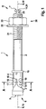
- An in Fig. 1 illustrated expansion dowel 1 is used to attach workpieces to a component.
- a hole or a hole is incorporated and for attaching the workpiece, the expansion anchor 1 is inserted or hit in this hole.
- the component is for example a concrete wall or a concrete floor of a building.
- the expansion anchor 1 comprises an anchor bolt 2.
- the anchor bolt 2 has a first end 5 with a first end portion 6 and a second end 7 with a second end portion 8.
- first end 5 in the Drill hole introduced and a second end 7 and a second end portion 8 of the anchor bolt 2 remain outside the borehole.
- a conical expansion body 3 is formed at the first end portion 6.
- an expansion sleeve 4 is arranged coaxially about the anchor bolt 2.
- the expansion sleeve 4 rests on the support ring 15, so that when inserting the expansion dowel 1 into the borehole and associated friction forces between the borehole wall and the expansion sleeve 4, the expansion sleeve 4 is not displaced in the direction of the second end 7 due to the resting on the support ring 5 is on the anchor bolt 2 ( Fig. 1 ).
- the expansion sleeve 4 has three longitudinal slots 16 in the direction of a longitudinal axis 10 of the anchor bolt 2, so that due to the axial longitudinal slots 16, the expansion sleeve 4 has three expansion segments 17.
- first projections 18 and second projections 19 are formed.
- the first protrusions 18 are formed closer to the first end 5 of the anchor bolt 2 than the second protrusions 19.
- the first and second protrusions 18, 19 also preferably have a different geometry.
- the engaging means 20 are an incorporated in the anchor bolt 2 thread 21, a washer 22 and a nut 23.
- the nut 23 has an unillustrated internal thread, which engages in the external thread 21 on the anchor bolt 2.
- rotating means receptacle 14 and a predetermined breaking point 25 are provided, which are integrally formed with the anchor bolt 2.
- the expansion anchor 1 is to be inserted or hammered into a borehole or a bore of a component. After insertion of the expansion anchor 1 in this well, the first end 5 is disposed within the wellbore and the second end 7 outside of the wellbore.
- the expansion sleeve 4 Due to frictional forces between the expansion sleeve 4 and the borehole wall as well as due to a positive connection with the projections 18, 19, the expansion sleeve 4 performs no rotational movement about the axis of rotation 9.
- the force applied by the wrench on the polygon 24 torque and the resulting rotational movement with a rotation angle of 120 ° of the anchor bolt 2 including the eccentric 11 on the anchor bolt 2 can thus a Initial spreading of the expansion sleeve 4 are performed on the borehole wall. Because of this initial spreading, there is a positive and preferably also positive connection between the expansion sleeve 4 and the concrete at the bore, so that thereby an axial movement of the expansion sleeve 4, ie a sleeve slip, is excluded.
- the anchor bolt 2 and thus also the expansion body 3 are screwed outward in the axial direction with respect to the longitudinal axis 10 by means of the engagement means 20, in which the nut 23 is screwed to the thread 21, so that due to the axial fixation as Initialversp Drung the expansion sleeve 4 with frictional forces between the expansion sleeve 4 and the borehole wall, also due to the projections 18, 19, which also allow a positive connection, with the expansion body 3, the expansion sleeve 4 at the expansion segments 17 additionally spread radially outward as Treasureversp Sonung so that permanently frictional forces and a bias between the expansion sleeve 4 and / or the spreader 3 and the borehole wall occur for a constant axial attachment of the expansion anchor 1 in the borehole, not shown, of the component, not shown.
- the Initialversp Drettive initially prepared by a rotational movement of the anchor bolt 2 includes an axial Displacement of the expansion sleeve 4 in the subsequent Treasureversp Drung due to an axial movement of the anchor bolt 2 from.
- a sleeve slip of the expansion sleeve 4 can be avoided in an advantageous manner, which would lead to a different embedment depth of the expansion anchor 1 in a disadvantageous manner.
- the expansion sleeve 4 can be performed on the concrete of the borehole even with hole diameters in the upper tolerance range and cracked concrete in prestressed concrete.
Description
Die vorliegende Erfindung betrifft einen Spreizdübel gemäß dem Oberbegriff des Anspruches 1.The present invention relates to an expansion anchor according to the preamble of claim 1.
Spreizdübel mit einem Ankerbolzen, einem Spreizkörper, Angriffsmitteln sowie eine den Ankerbolzen umgebende Spreizhülse dienen dazu, Werkstücke an einem Bauteil zu befestigen. Hierzu wird in das Bauteil, z. B. eine Betonwand oder eine Betondecke, eine Bohrung eingearbeitet und anschließend der Spreizdübel in die Bohrung eingeschoben. Mit den Angriffsmitteln wird der konische Spreizkörper axial an dem Ankerbolzen bewegt, so dass dadurch der Spreizkörper die Spreizhülse radial nach außen drückt und eine Verankerung des Spreizdübels aufgrund von radialen Kräften zwischen der Spreizhülse bzw. dem Spreizkörper und dem Bauteil, z. B. dem Beton an der Bohrung, besteht. Dadurch können Werkstücke oder Gegenstände an dem Spreizdübel befestigt werden.Expansion dowel with an anchor bolt, a spreader, attacking means and a surrounding the anchor bolt expansion sleeve serve to attach workpieces to a component. For this purpose, in the component, for. As a concrete wall or a concrete pavement, a hole incorporated and then pushed the expansion dowel into the hole. With the engagement means of the conical expansion body is axially moved to the anchor bolt, thereby characterized the expansion body pushes the expansion sleeve radially outward and anchoring of the expansion anchor due to radial forces between the expansion sleeve and the expansion body and the component, for. As the concrete to the hole exists. As a result, workpieces or objects can be attached to the expansible plug.
Zwischen der Spreizhülse und der Bohrlochwandung an dem Bauteil bewirkt somit eine Reibkraft zwischen der Bohrlochwandung und der Spreizhülse eine Verankerung des Spreizdübels. Die konischen Spreizkörper sind im Allgemeinen rotationssymmetrisch zu einer Längsachse des Ankerbolzens bzw. des Spreizkörpers ausgebildet.Between the expansion sleeve and the borehole wall on the component thus causes a frictional force between the borehole wall and the expansion sleeve anchoring of the expansion anchor. The conical expansion bodies are generally rotationally symmetrical to a longitudinal axis of the anchor bolt or of the expansion body.
Als Angriffsmittel werden beispielsweise ein Gewinde an dem Ankerbolzen, eine Beilagscheibe und eine Mutter eingesetzt. Durch ein Verschrauben der Mutter auf dem Gewinde des Ankerbolzens wird die Beilagscheibe gegen den Beton an einem Bohrlochmund gedrückt und dadurch eine axiale Bewegung des Ankerbolzens und damit auch des konischen Spreizkörpers bewirkt. Auf die Mutter ist damit ein Drehmoment aufzubringen, um diese mit dem Gewinde an dem Ankerbolzen zu verschrauben bzw. einzuschrauben. Bei einer Anwendung des Spreizdübels in Zugzonen, d. h. bei gerissenem Beton in Spannbeton bei dem kleine Risse unten an der Spannbetondecke auftreten, vergrößert sich der Durchmesser des Bohrlochs während des Aufspreizens der Spreizhülse mit dem Spreizkörper. Dadurch kommt es während der radialen Verspannung der Spreizhülse an dem Beton an der Bohrung zu einer zusätzlichen axialen Verschiebung des Ankerbolzens mit der Spreizhülse, einem sogenannten Nachspreizen. Der Spreizkörper, d. h. hier insbesondere die konische Geometrie des Spreizkörpers, muss so ausgelegt sein, dass sowohl in einem unteren Toleranzbereich eines Bohrlochdurchmessers als auch in einem oberen Toleranzbereich des Bohrlochdurchmessers die erforderliche Spreizkraft, d. h. radiale Vorspannung zwischen der Spreizhülse und dem Beton an dem Bohrloch, erreicht werden kann. Je nach dem unterschiedlichen Durchmesser des Bohrloches im Toleranzbereich führt dies zu verschiedenen axialen Verschiebungswegen zwischen dem Ankerbolzen und der Spreizhülse. Bei Bohrlochdurchmessern im oberen Toleranzbereich kann es zusätzlich zu einer Verschiebung der Spreizhülse relativ zu dem Bohrloch kommen (Hülsenschlupf). Bei einem Hülsenschlupf ragen die verschiedenen Ankerbolzen bei einem unterschiedlichen Hülsenschlupf unterschiedlich weit aus dem Bohrloch heraus und eine axiale Verschiebung der Spreizhülse in Richtung zu dem Bohrlochmund führt auch zu nachteiligen unterschiedlichen Verankerungstiefen des Spreizdübels in der Bohrung. Die Folge ist eine erhöhte Streuung der Bruchlast der Spreizdübel.As a means of attack, for example, a thread on the anchor bolt, a washer and a nut are used. By screwing the nut on the thread of the anchor bolt, the washer is pressed against the concrete at a borehole mouth and thereby causes an axial movement of the anchor bolt and thus also of the conical expansion body. On the nut is thus apply a torque to screw or screw this with the thread on the anchor bolt. When using the expansion anchor in tension zones, d. H. in cracked concrete in prestressed concrete in which small cracks occur at the bottom of the prestressed concrete ceiling, the diameter of the borehole increases during the spreading of the expansion sleeve with the expansion body. As a result, during the radial tensioning of the expansion sleeve on the concrete at the bore, an additional axial displacement of the anchor bolt with the expansion sleeve occurs, a so-called post-spreading. The spreader, d. H. Here, in particular, the conical geometry of the expansion body, must be designed so that both in a lower tolerance range of a borehole diameter and in an upper tolerance range of the borehole diameter, the required spreading force, d. H. radial bias between the expansion sleeve and the concrete at the borehole, can be achieved. Depending on the different diameter of the borehole in the tolerance range, this leads to different axial displacement paths between the anchor bolt and the expansion sleeve. In the case of borehole diameters in the upper tolerance range, in addition to a displacement of the expansion sleeve relative to the borehole can occur (sleeve slip). In the case of a sleeve slip, the different anchor bolts protrude at different heel slips differently far out of the borehole and an axial displacement of the expansion sleeve in the direction of the borehole mouth also leads to disadvantageous different anchoring depths of the expansion anchor in the bore. The result is an increased dispersion of the breaking load of the expansion dowel.
Die
Ein gattungsgemässer Spreizdübel mit einem Exzenterelement geht aus der
Die
Die Aufgabe der vorliegenden Erfindung besteht darin, einen Spreizdübel zur Verfügung zu stellen, bei dem eine axiale Verschiebung der Spreizhülse, insbesondere bei einem Bohrlochdurchmesser im unteren Toleranzbereich bzw. einer Hohllage, vermieden werden kann.The object of the present invention is to provide an expansion anchor, in which an axial displacement of the expansion sleeve, in particular in a borehole diameter in the lower tolerance range or a hollow layer, can be avoided.
Diese Aufgabe wird gelöst mit einem Spreizdübel, umfassend einen Ankerbolzen mit einem Spreizkörper an einem ersten Endabschnitt des Ankerbolzens und mit einer Längsachse, ein Angriffsmittel an dem Ankerbolzen zur Lastaufnahme, und eine den Ankerbolzen umgebende Spreizhülse, wobei der Spreizdübel wenigstens eine Exzentergeometrie aufweist, so dass mittels einer Rotationsbewegung des Ankerbolzens um die Längsachse als Rotationsachse eine Aufspreizung der Spreizhülse ausführbar ist, und wobei der Ankerbolzen an dem anderen zweiten Endabschnitt mit einer Drehmittelaufnahme und einer Sollbruchstelle zur Begrenzung des von der Drehmittelaufnahme aufnehmbaren Drehmomentes versehen ist, wobei die Drehmittelaufnahme und die Sollbruchstelle einteilig mit dem Ankerbolzen ausgebildet sind.This object is achieved with an expansion anchor, comprising an anchor bolt with an expansion body at a first end portion of the anchor bolt and with a longitudinal axis, an engaging means on the anchor bolt for load bearing, and an anchor sleeve surrounding the expansion sleeve, wherein the expansion anchor has at least one eccentric geometry, so that by means of a rotational movement of the anchor bolt about the longitudinal axis as a rotation axis spreading of the expansion sleeve is executable, and wherein the anchor bolt is provided at the other second end portion with a Drehmittelaufnahme and a predetermined breaking point for limiting the recordable by the Drehmittelaufnahme torque, wherein the Drehmittelaufnahme and the predetermined breaking point in one piece are formed with the anchor bolt.
Mit Hilfe der wenigstens einen Exzentergeometrie kann ohne einer axialen Bewegung des Ankerbolzens mit dem Spreizkörper eine Aufspreizung der Spreizhülse erfolgen. Eine Aufspreizung der Spreizhülse, d. h. eine radiale Bewegung der Spreizhülse in Richtung von der Längsachse des Ankerbolzens weg, führt zu einer radialen Vorspannkraft zwischen der Spreizhülse und dem Werkstoff, z. B. Beton, an der Bohrung. Mit Hilfe dieser Vorspannung zwischen der Spreizhülse und dem Werkstoff an der Bohrung kann der Spreizdübel in der Bohrung verankert werden. Da jedoch zum Aufspreizen der Spreizhülse keine axiale Bewegung des Ankerbolzens erforderlich ist, welche zu einem Hülsenschlupf führen kann, d. h. einer axialen Bewegung der Spreizhülse in Richtung zu einem Bohrlochmund, ist ein Hülsenschlupf ausgeschlossen. Lediglich mit der Rotationsbewegung des Ankerbolzens ist es möglich, die Spreizhülse an dem Werkstoff der Bohrung zu verspreizen.With the aid of the at least one eccentric geometry, spreading of the expansion sleeve can take place without an axial movement of the anchor bolt with the expansion body. A spreading of the expansion sleeve, ie a radial movement of the expansion sleeve in the direction of the longitudinal axis of the anchor bolt away, leading to a radial biasing force between the expansion sleeve and the material, for. As concrete, at the bore. With the help of this bias between the expansion sleeve and the material at the bore of the expansion anchor can be anchored in the hole. However, since for spreading the expansion sleeve no axial movement of the anchor bolt is required, which can lead to a sleeve slip, ie an axial movement of the expansion sleeve towards a borehole mouth, a sleeve slip is excluded. Only with the rotational movement of the anchor bolt, it is possible to spreader the expansion sleeve on the material of the bore.
Insbesondere umfasst der Spreizdübel mehrere Exzentergeometrien. Mit Hilfe von mehreren Exzentergeometrien kann tangential umlaufend eine gleichmäßigere Aufspreizung der Spreizhülse ausgeführt werden.In particular, the expansion anchor comprises a plurality of eccentric geometries. With the aid of several eccentric geometries, a more even spreading of the expansion sleeve can be performed tangentially around the circumference.
In einer weiteren Ausgestaltung ist die wenigstens eine Exzentergeometrie an dem Ankerbolzen und/oder an der Spreizhülse ausgebildet. Zweckmäßig liegt eine Exzentergeometrie an dem Ankerbolzen auf einer Exzentergeometrie an der Spreizhülse auf.In a further embodiment, the at least one eccentric geometry is formed on the anchor bolt and / or on the expansion sleeve. Expediently, an eccentric geometry on the anchor bolt rests on an eccentric geometry on the expansion sleeve.
In einer ergänzenden Ausführungsform ist die wenigstens eine Exzentergeometrie an dem Spreizkörper oder außerhalb des Spreizkörpers an dem Ankerbolzen ausgebildet.In an additional embodiment, the at least one eccentric geometry is formed on the spreader body or outside the spreader body on the anchor bolt.
Erfindungsgemäss ist der Ankerbolzen an dem anderen zweiten Endabschnitt mit einer Drehmittelaufnahme, z. B. einen Mehrkant, und einer Sollbruchstelle zur Begrenzung des von der Drehmittelaufnahme aufnehmbaren Drehmomentes versehen. Mit der Drehmittelaufnahme kann der Spreizdübel in eine Rotationsbewegung versetzt werden, um mittels der wenigstens einen Exzentergeometrie die Spreizhülse aufzuspreizen und eine Verspannung zwischen der Spreizhülse und dem Beton an der Bohrung zu bewirken. Die Sollbruchstelle bewirkt, dass ein vorgesehenes Drehmoment zur Versetzung des Ankerbolzens in die Drehbewegung nicht überschritten wird. An dem Mehrkant kann beispielsweise ein Schraubschlüssel angesetzt werden.According to the invention, the anchor bolt at the other second end portion with a rotating means receiving, for. B. a polygon, and a predetermined breaking point to limit the recordable by the rotational means receiving torque. With the rotating means receiving the expansion dowel can be set in a rotational movement in order to spread the expansion sleeve by means of at least one eccentric geometry and to cause a tension between the expansion sleeve and the concrete at the bore. The predetermined breaking point causes an intended torque for the displacement of the anchor bolt is not exceeded in the rotational movement. For example, a wrench can be attached to the polygon.
Alternativ kann vorgesehen sein, dass das wenigstens eine Angriffsmittel ein Gewinde an dem Ankerbolzen und eine Mutter aufweist, die auf dem Gewinde angeordnet ist, wobei eine Einrichtung vorgesehen ist, welche die Mutter bis zum Erreichen eines Grenzdrehmomentes drehfest am Gewinde hält und nach Übersteigen des Grenzdrehmomentes die Mutter für eine Drehung relativ zum Gewinde freigibt, insbesondere irreversibel freigibt. Die Einrichtung kann zum Beispiel durch eine Sollbruchstelle realisiert werden, beispielsweise an einen Stift, der zwischen Mutter und Ankerbolzen verläuft.Alternatively, it can be provided that the at least one engagement means has a thread on the anchor bolt and a nut which is arranged on the thread, wherein a device is provided which rotatably holds the nut until reaching a limit torque on the thread and after exceeding the limit torque the nut releases for rotation relative to the thread, in particular irreversibly releases. The device can be realized for example by a predetermined breaking point, for example, to a pin which extends between the nut and anchor bolt.
Die Einrichtung kann auch durch Reibflächen zwischen Ankerbolzen und Mutter gebildet sein. Gemäß der vorliegenden Ausführungsform ist die Mutter so lange drehfest mit der Ankerstange verbunden, bis das Grenzdrehmoment erreicht ist, welches dem Abschluss des Setzvorgangs entspricht. Nach Erreichen des Grenzdrehmomentes kann die Mutter dann längs des Gewindes geschraubt werden. Gemäß dieser Ausführungsform kann eine separate Drehmittelaufnahme entbehrlich sein, da sowohl das Setzen des Ankers als auch das Befestigen der Last mittels ein und derselben Mutter durchgeführt werden kann.The device can also be formed by friction surfaces between the anchor bolt and nut. According to the present embodiment, the nut is rotatably connected to the anchor rod until the limit torque is reached, which corresponds to the completion of the setting process. After reaching the limit torque, the nut can then be screwed along the thread. According to this embodiment, a separate Drehmittelaufnahme can be dispensable, since both the setting of the anchor and the attachment of the load can be performed by means of one and the same mother.
In einer Variante ist die wenigstens eine Exzentergeometrie zwischen dem Ankerbolzen und einer radialen Außenseite der Spreizhülse ausgebildet und/oder die wenigstens eine Exzentergeometrie ist einteilig an dem Ankerbolzen oder der Spreizhülse ausgebildet. Bei einer einteiligen Ausbildung der wenigstens einen Exzentergeometrie an dem Ankerbolzen oder an der Spreizhülse ist diese besonders einfach bei der Herstellung, beispielsweise beim Urformen, mit herzustellen und andererseits besteht ein besonders fester Verbund zwischen der wenigstens einen Exzentergeometrie und dem Ankerbolzen oder der Spreizhülse.In a variant, the at least one eccentric geometry is formed between the anchor bolt and a radial outer side of the expansion sleeve and / or the at least one eccentric geometry is formed integrally on the anchor bolt or the expansion sleeve. In a one-piece design of the at least one eccentric geometry on the anchor bolt or on the expansion sleeve, this is particularly easy to manufacture, for example, during prototyping, and on the other hand there is a particularly strong bond between the at least one eccentric geometry and the anchor bolt or the expansion sleeve.
Zweckmäßig ist mittels eine axialen Bewegung des Ankerbolzens aufgrund einer konischen Geometrie des Spreizkörpers die Spreizhülse aufspreizbar. Nach der Verspannung der Spreizhülse mittels der wenigstens einen Exzentergeometrie aufgrund einer Rotationsbewegung des Ankerbolzens als Initialverspreizung, um einen Hülsenschlupf zu verhindern, kann durch eine axiale Bewegung des Ankerbolzens eine zusätzliche Verspreizung der Spreizhülse an dem Werkstoff der Bohrung ausgeführt werden. Beispielsweise auch beim Einsatz des Spreizdübels in Zugzonen, d. h. gerissenem Beton, kann es erforderlich sein, dass eine entsprechende Nachspreizung im Anschluss an die Initialverspreizung erforderlich ist. Nach der Initialverspreizung kann somit eine zusätzliche Aufspreizung der Spreizhülse, z. B. als dauerhafte Verspreizung aufgrund einer an dem Ankerbolzen wirkenden Zugkraft, ausgeführt werden. Eine Dauerverspreizung der Spreizhülse ist erforderlich, um dauerhaft an dem Spreizdübel Lasten befestigen zu können. Diese Dauerverspreizung kann, wie bereits erwähnt, durch eine dauerhafte wirkende Zugkraft an dem Ankerbolzen aufgrund einer Auflage einer Beilagscheibe oder einer Mutter am Beton bewirkt sein.Appropriately, by means of an axial movement of the anchor bolt due to a conical geometry of the expansion body, the expansion sleeve can be spread open. After the bracing of the expansion sleeve by means of the at least one eccentric geometry due to a rotational movement of the anchor bolt as Initialverspreizung to prevent sleeve slippage, an additional expansion of the expansion sleeve can be performed on the material of the bore by an axial movement of the anchor bolt. For example, even when using the expansion anchor in tensile zones, ie cracked concrete, it may be necessary that a corresponding Nachspreizung following the Initialverspreizung is required. After the initial expansion can thus be an additional spreading of the expansion, z. B. as a permanent spread due to a force acting on the anchor bolt tensile force, running. A Dauerverspreizung the expansion sleeve is required to permanently on the Fastening dowel to fasten loads. This permanent spread can, as already mentioned, be effected by a permanent acting tensile force on the anchor bolt due to a support of a washer or a nut on the concrete.
In einer weiteren Ausführungsform umfasst das wenigstens eine Angriffsmittel ein Gewinde an dem Ankerbolzen, eine Beilagscheibe und eine Mutter.In a further embodiment, the at least one engaging means comprises a thread on the anchor bolt, a washer and a nut.
Erfindungsgemäß kann der Anker auch einen Nagelkopf am Ankerbolzen aufweisen; eine Mutter kann dann entbehrlich sein. Zum Verdrehen und Setzen der Ankerstange kann das Angriffsmittel z.B. als Mehrkant ausgebildet sein, der am Nagelkopf angeordnet ist.According to the invention, the anchor may also have a nail head on the anchor bolt; a mother can then be dispensable. For twisting and setting the anchor rod, the attacking means may e.g. be formed as a polygon, which is arranged on the nail head.
Insbesondere sind das wenigsten eine Angriffsmittel an einem zweiten Endabschnitt des Ankerbolzens ausgebildet.In particular, at least one engaging means are formed on a second end portion of the anchor bolt.
In einer weiteren Ausgestaltung besteht der Ankerbolzen und/oder der Spreizkörper und/oder das wenigstens eine Angriffsmittel wenigstens teilweise, insbesondere vollständig, aus Metall, z. B. Stahl oder Aluminium, und/oder mit dem Spreizdübel ist ein in dieser Schutzrechtsanmeldung beschriebenes Verfahren ausführbar.In a further embodiment, the anchor bolt and / or the expansion body and / or the at least one engagement means at least partially, in particular completely, made of metal, for. As steel or aluminum, and / or with the expansion anchor described in this patent application process is executable.
Erfindungsgemäßes Verfahren zur Befestigung eines Spreizdübels, insbesondere eines in dieser Schutzrechtsanmeldung beschriebenen Spreizdübels, mit den Schritten: Einführen des Spreizdübels in ein Bohrloch, Aufspreizen einer Spreizhülse des Spreizdübels, so dass die Spreizhülse radial mit einer Bohrlochwandung verspreizt wird, wobei der Ankerbolzen mit dem Spreizkörper in eine Rotationsbewegung versetzt wird und mit wenigstens einer Exzentergeometrie aufgrund der Rotationsbewegung die Spreizhülse aufgespreizt wird. Die Rotationsbewegung ist dabei vorzugsweise eine Drehbewegung um maximal 360°. Bei mehr als einer Exzentergeometrie entspricht der Drehwinkel vorzugsweise 360° geteilt durch die Anzahl der wirksamen Exzentergeometrien.Method according to the invention for fastening an expansion anchor, in particular an expansion anchor described in this patent application, comprising the steps of: inserting the expansion anchor into a borehole, spreading an expansion sleeve of the expansion anchor, so that the expansion sleeve is spread radially with a borehole wall, wherein the anchor bolt with the expansion body in a rotational movement is offset and with at least one eccentric geometry due to the rotational movement, the expansion sleeve is spread. The rotational movement is preferably a rotational movement of a maximum of 360 °. For more than one eccentric geometry, the angle of rotation preferably corresponds to 360 ° divided by the number of effective eccentric geometries.
In einer ergänzenden Variante entspricht die Rotationsachse der Rotationsbewegung einer Längsachse des Ankerbolzens.In a supplementary variant, the axis of rotation corresponds to the rotational movement of a longitudinal axis of the anchor bolt.
In einer weiteren Variante wird an einer Drehmittelaufnahme an dem Ankerbolzen außerhalb des Bohrloches ein Drehmoment aufgebracht, um den Ankerbolzen mit dem Spreizkörper in die Rotationsbewegung zu versetzten.In a further variant, a torque is applied to a rotating means receiving on the anchor bolt outside the borehole in order to offset the anchor bolt with the spreader in the rotational movement.
In einer weiteren Ausgestaltung wird der Ankerbolzen nach oder während der Aufspreizung der Spreizhülse mit der wenigstens einer Exzentergeometrie aufgrund der Rotationsbewegung des Ankerbotzens in eine axiale Translationsbewegung in Richtung zu einem Bohrlochmund versetzt und dadurch wird aufgrund einer konischen Geometrie des Spreizkörpers die Spreizhülse aufgespreizt.In a further embodiment, the anchor bolt is displaced after or during the spreading of the expansion sleeve with the at least one eccentric geometry due to the rotational movement of the anchor poking in an axial translational movement in the direction of a borehole mouth and thereby the expansion sleeve is spread due to a conical geometry of the expansion body.
In einer zusätzlichen Ausgestaltung wird der Ankerbolzen mit wenigstens einem Angriffsmittel, z. B. indem eine Mutter in ein Gewinde des Ankerbolzens geschraubt wird, in die axiale Translationsbewegung versetzt. Eine axiale Translationsbewegung kann durch ein Verschrauben der Mutter mit dem Gewinde des Ankerbolzens bewirkt werden und eine derartige Verschraubung bewirkt eine dauerhafte Zugkraft an dem Ankerbolzen und diese Zugkraft führt zu einer Dauerverspreizung der Spreizhülse aufgrund der konischen Geometrie des Spreizkörpers. Nach der Initialverspreizung aufgrund der Rotationsbewegung des Ankerbolzens kann somit eine Dauerverspreizung aufgrund einer axialen Translationsbewegung des Ankerbolzens ausgeführt werden. Eine Rückbewegung der Spreizhülse aufgrund einer derartigen Dauerverspreizung wegen der axialen Translationsbewegung ist jedoch ausgeschlossen, weil eine Bewegung des Ankerbolzens aufgrund des Aufliegens der Beilagscheibe am Beton im Bereich des Bohrlochmundes ausgeschlossen ist.In an additional embodiment of the anchor bolt with at least one attack means, for. B. by a nut is screwed into a thread of the anchor bolt, offset in the axial translational movement. An axial translation movement can be effected by screwing the nut with the thread of the anchor bolt and such a screw causes a permanent tensile force on the anchor bolt and this tensile force leads to a permanent spread of the expansion sleeve due to the conical geometry of the expansion body. After the initial expansion due to the rotational movement of the anchor bolt thus a permanent spread can be carried out due to an axial translational movement of the anchor bolt. A return movement of the expansion sleeve due to such Dauerverspreizung because of the axial translation movement is excluded, however, because a movement of the anchor bolt is excluded due to the bearing of the washer on the concrete in the field of Bohrlochmundes.
In einer ergänzenden Ausgestaltung weist der Ankerbolzen einen Auflagering auf und der Spreizkörper stützt sich auf dem Auflagering ab, so dass sich die Spreizhülse beim Einschieben in die Bohrung an dem Auflagering abstützt. Bei einem Herausschrauben des Ankerbolzens mit den Angriffsmitteln, z. B. der Mutter, ist eine axiale Befestigung der Spreizhülse erforderlich, damit eine Aufspreizung der Spreizhülse erfolgen kann. Dies erfolgt mittels Reibschluss, z. B. dadurch, dass die Spreizhülse zusätzlich mit Vorsprüngen versehen ist.In an additional embodiment, the anchor bolt on a support ring and the spreader is based on the support ring, so that the expansion sleeve is supported when inserted into the bore on the support ring. When unscrewing the anchor bolt with the offensive, z. As the mother, an axial attachment of the expansion sleeve is required so that a spreading of the expansion can be done. This is done by means of frictional engagement, z. B. in that the expansion sleeve is additionally provided with projections.
In einer ergänzenden Variante ist die Spreizhülse bis zu einer Mutter einer Beilagscheibe geführt, d. h. liegt auf einem Angriffsmittel auf, und bei einem Herausschrauben des Ankerbolzens wird die axiale Fixierung der Spreizhülse nicht durch eine Reibung zwischen der Bohrlochwandung und der Spreizhülse zur Verfügung gestellt, sondern dadurch, dass die Spreizhülse auf wenigstens einem Angriffsmittel, z. B. einer Beilagscheibe, aufliegt.In an additional variant, the expansion sleeve is guided to a nut of a washer, d. H. is located on an attack means, and upon unscrewing the anchor bolt, the axial fixation of the expansion sleeve is not provided by a friction between the borehole wall and the expansion sleeve, but in that the expansion sleeve on at least one attack means, for. B. a washer, rests.
Im Nachfolgenden wird ein Ausführungsbeispiel der Erfindung unter Bezugnahme auf die beigefügten Zeichnungen näher beschrieben. Es zeigt:
- Fig. 1
- einen Längsschnitt eines Spreizdübel,
- Fig. 2
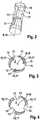
- eine perspektivische Teilansicht des Spreizdübels ohne Spreizhülse,
- Fig. 3
- einen Querschnitt A-A gemäß
Fig. 1 vor dem Verdrehen und - Fig. 4
- den Querschnitt A-A gemäß
Fig. 1 nach dem Verdrehen.
- Fig. 1
- a longitudinal section of an expansion anchor,
- Fig. 2
- a partial perspective view of the expansion anchor without expansion sleeve,
- Fig. 3
- a cross section AA according to
Fig. 1 before twisting and - Fig. 4
- the cross section AA according to
Fig. 1 after twisting.
Ein in
Der Spreizdübel 1 umfasst einen Ankerbolzen 2. Der Ankerbolzen 2 weist ein erstes Ende 5 mit einem ersten Endabschnitt 6 auf und ein zweites Ende 7 mit einem zweiten Endabschnitt 8. Beim Einführen des Spreizdübels 1 in ein Bohrloch eines Bauteils wird das erste Ende 5 in das Bohrloch eingeführt und ein zweites Ende 7 bzw. auch ein zweiter Endabschnitt 8 des Ankerbolzens 2 bleiben außerhalb des Bohrloches. Einteilig mit dem Ankerbolzen 2 ist am ersten Endabschnitt 6 ein konischer Spreizkörper 3 ausgebildet. Zwischen dem Spreizkörper 3 und einem einteilig mit dem Ankerbolzen 2 ausgebildetem Auflagering 15 ist um den Ankerbolzen 2 koaxial eine Spreizhülse 4 angeordnet. Die Spreizhülse 4 liegt auf dem Auflagering 15 auf, so dass beim Einschieben des Spreizdübels 1 in das Bohrloch und damit verbundenen Reibungskräften zwischen der Bohrlochwandung und der Spreizhülse 4 die Spreizhülse 4 aufgrund des Aufliegens auf dem Auflagering 5 nicht in Richtung zu dem zweiten Ende 7 verschoben wird auf dem Ankerbolzen 2 (
Die Spreizhülse 4 weist drei Längsschlitze 16 in Richtung einer Längsachse 10 des Ankerbolzens 2 auf, so dass aufgrund der axialen Längsschlitze 16 die Spreizhülse 4 drei Spreizsegmente 17 aufweist. An der Spreizhülse 4, insbesondere den Spreizsegmenten 17, sind erste Vorsprünge 18 und zweite Vorsprünge 19 ausgebildet. Die ersten Vorsprünge 18 sind näher an dem ersten Ende 5 des Ankerbolzens 2 ausgebildet als die zweiten Vorsprünge 19. Die ersten und zweiten Vorsprünge 18, 19 weisen ferner auch vorzugsweise eine unterschiedliche Geometrie auf.The
Am zweiten Endabschnitt 8 des Ankerbolzens 2 sind drei Angriffsmittel 20 angeordnet. Die Angriffsmittel 20 sind ein in den Ankerbolzen 2 eingearbeitetes Gewinde 21, eine Beilagscheibe 22 und eine Mutter 23. Die Mutter 23 weist ein nicht dargestelltes Innengewinde auf, welches in das Außengewinde 21 an dem Ankerbolzen 2 eingreift. Ferner sind am zweiten Endabschnitt 8 eine als Mehrkant 24 ausgebildete Drehmittelaufnahme 14 und eine Sollbruchstelle 25 vorhanden, welche einteilig mit dem Ankerbolzen 2 ausgebildet sind.At the second end portion 8 of the
Zur Befestigung von Werkstücken an dem Spreizdübel 1 ist der Spreizdübel 1 in ein Bohrloch bzw. eine Bohrung eines Bauteils einzuführen bzw. einzuschlagen. Nach dem Einschieben des Spreizdübels 1 in dieses Bohrloch ist das erste Ende 5 innerhalb des Bohrloches und das zweite Ende 7 außerhalb des Bohrloches angeordnet.For fixing workpieces to the expansion anchor 1, the expansion anchor 1 is to be inserted or hammered into a borehole or a bore of a component. After insertion of the expansion anchor 1 in this well, the
An dem Ankerbolzen 2 in Richtung zu dem zweiten Endabschnitt 8 des Ankerbolzens 2 sind nach dem Spreizkörper 3 an dem Ankerbolzen 2 drei Exzentergeometrien 11 (
Nach der Initialverspreizung wird mittels der Angriffsmittel 20, in dem die Mutter 23 mit dem Gewinde 21 verschraubt wird, der Ankerbolzen 2 und damit auch der Spreizkörper 3 in axialer Richtung bezüglich der Längsachse 10 nach außen geschraubt, so dass dadurch aufgrund der axialen Fixierung als Initialverspreizung der Spreizhülse 4 mit Reibungskräften zwischen der Spreizhülse 4 und der Bohrlochwandung, auch aufgrund der Vorsprünge 18, 19, die auch eine formschlüssige Verbindung ermöglichen, wird mit dem Spreizkörper 3 die Spreizhülse 4 an den Spreizsegmenten 17 zusätzlich radial nach außen gespreizt als Dauerverspreizung, so dass dauerhaft Reibkräfte und eine Vorspannung zwischen der Spreizhülse 4 und/oder dem Spreizkörper 3 und der Bohrlochwandung auftreten für eine ständig axiale Befestigung des Spreizdübels 1 in dem nicht dargestellten Bohrloch des nicht dargestellten Bauteiles.After the initial spreading, the
Nach dem Einbringen des Spreizdübels 1 in das Bohrloch wird somit in einem ersten Arbeitsschritt eine Initialverspreizung zwischen der Spreizhülse 4 und dem Beton an der Bohrung hergestellt, um einen Hülsenschlupf, d. h. eine axiale Bewegung der Spreizhülse 4 während der Herstellung der Dauerverspreizung, zu vermeiden. Während der Dauerverspreizung wird aufgrund einer Zugkraft in dem Ankerbolzen 2, weil die Beilagscheibe 22 am Beton im Bereich des Bohrlochmundes aufliegt, der Ankerbolzen 2 axial in Richtung zu dem Bohrlochmund bewegt. Aufgrund der bereits vorhandenen Initialverspreizung führt jedoch die Spreizhülse 4 keine axiale Bewegung mit aus.After the introduction of the expansion anchor 1 into the wellbore, an initial displacement between the
Insgesamt betrachtet sind mit dem erfindungsgemäßen Spreizdübel 1 wesentliche Vorteile verbunden. Die mittels einer Rotationsbewegung des Ankerbolzens 2 zunächst hergestellte Initialverspreizung schließt eine axiale Verschiebung der Spreizhülse 4 in der darauffolgenden Dauerverspreizung aufgrund einer axialen Bewegung des Ankerbolzens 2 aus. Dadurch kann in vorteilhafter Weise ein Hülsenschlupf der Spreizhülse 4 vermieden werden, was zu einer unterschiedlichen Einbindetiefe des Spreizdübels 1 in nachteiliger Weise führen würde. Mit der nachfolgenden Dauerverspreizung können auch bei Bohrlochdurchmessern im oberen Toleranzbereich sowie bei gerissenem Beton in Spannbeton eine Dauerverspreizung der Spreizhülse 4 am Beton des Bohrloches ausgeführt werden.Overall, significant advantages are associated with the expansion dowel 1 according to the invention. The Initialverspreizung initially prepared by a rotational movement of the
Claims (15)
- Expansion anchor (1), comprising- an anchor bolt (2) with an expansion body (3) on a first end section (6) of the anchor bolt (2) and with a longitudinal axis (10),- at least one engagement means (20) on the anchor bolt (2) for load absorption, and- an expansion sleeve (4) surrounding the anchor bolt (2),wherein the expansion anchor (1) has at least one eccentric geometry (11, 12), such that an expansion of the expansion sleeve (4) can be effected by means of a rotational movement of the anchor bolt (2) about the longitudinal axis (10) as the axis of rotation (9),
characterised in that
the anchor bolt (2) is provided on the other, second end section (8) with a receptacle (14) of a turning means and with a predetermined breaking point (25) for limiting the torque that can be absorbed by the turning means receptacle (14), and the turning means receptacle (14) and the predetermined breaking point (25) are formed integrally with the anchor bolt (2). - Expansion anchor according to Claim 1,
characterised in that
the expansion anchor (1) includes a plurality of eccentric geometries (11, 12). - Expansion anchor according to Claim 1 or 2,
characterised in that
the at least one eccentric geometry (11, 12) is formed on the anchor bolt (2) and/or on the expansion sleeve (4). - Expansion anchor according to one or more of the preceding claims,
characterised in that
the at least one eccentric geometry (11, 12) is formed on the expansion body (3) or outside the expansion body (3) on the anchor bolt (2). - Expansion anchor according to one or more of the preceding claims,
characterised in that
the turning means receptacle (14) is configured as a polygon (24). - Expansion anchor according to one or more of the preceding claims,
characterised in that
the at least one eccentric geometry (11, 12) is formed between the anchor bolt (2) and a radially outer side of the expansion sleeve (4)
and/or
the at least one eccentric geometry (11, 12) is formed integrally on the anchor bolt (2) or on the expansion sleeve (4). - Expansion anchor according to one or more of the preceding claims,
characterised in that
the expansion sleeve (4) can be expanded by means of an axial movement of the anchor bolt (2) as a result of a conical geometry of the expansion body (3). - Expansion anchor according to one or more of the preceding claims,
characterised in that
the at least one engagement means (20) includes a thread (21) on the anchor bolt (2), a washer (22) and a nut (23). - Expansion anchor according to one or more of the preceding claims,
characterised in that
the at least one engagement means (20) is formed on a second end section (8) of the anchor bolt (2). - Expansion anchor according to one or more of the preceding claims,
characterised in that
the anchor bolt (2) and/or the expansion body (3) and/or the at least one engagement means (20) are made at least partially, in particular completely, of metal, for example steel. - Method for fastening an expansion anchor (1) according to one or more of the preceding claims, comprising the steps:- insertion of the expansion anchor (1) according to one or more of the preceding claims into a drill hole,- expansion of an expansion sleeve (4) of the expansion anchor (1), so that the expansion sleeve (4) Is braced radially against a wall of the drill hole,wherein
a rotational movement is imparted to the expansion bolt (2) with the expansion body (3) and the expansion sleeve (4) is expanded by means of at least one eccentric geometry (11, 12) as a result of the rotational movement. - Method according to Claim 11,
characterised in that
the axis of rotation (9) of the rotational movement coincides with a longitudinal axis (10) of the anchor bolt (2). - Method according to Claim 11 or 12,
characterised in that
a torque is applied to a receptacle (14) of the turning means on the anchor bolt (2) outside the drill hole in order to impart the rotational movement to the anchor bolt (2) with the expansion body (3). - Method according to one or more of Claims in 11 to 13,
characterised in that
after or during the expansion of the expansion sleeve (4) by means of the at least one eccentric geometry (11, 12), an axially translational movement towards the mouth of a drill hole is imparted to the anchor bolt (2) as a result of the rotational movement of the anchor bolt (2), and the expansion sleeve (4) is thereby expanded as a result of a conical geometry of the expansion body (3). - Method according to Claim 14,
characterised in that
the axially translational movement is imparted to the anchor bolt (2) by means of at least one engagement means (20), for example in that a nut (23) is screwed on a thread (21) of the anchor bolt (2).
Applications Claiming Priority (1)
| Application Number | Priority Date | Filing Date | Title |
|---|---|---|---|
| DE201110007570 DE102011007570A1 (en) | 2011-04-18 | 2011-04-18 | expansion anchor |
Publications (2)
| Publication Number | Publication Date |
|---|---|
| EP2514979A1 EP2514979A1 (en) | 2012-10-24 |
| EP2514979B1 true EP2514979B1 (en) | 2016-04-27 |
Family
ID=45819051
Family Applications (1)
| Application Number | Title | Priority Date | Filing Date |
|---|---|---|---|
| EP12158346.2A Active EP2514979B1 (en) | 2011-04-18 | 2012-03-07 | expansion anchor |
Country Status (6)
| Country | Link |
|---|---|
| US (1) | US9133871B2 (en) |
| EP (1) | EP2514979B1 (en) |
| JP (1) | JP5959904B2 (en) |
| CN (1) | CN102748354A (en) |
| DE (1) | DE102011007570A1 (en) |
| TW (1) | TW201243170A (en) |
Families Citing this family (18)
| Publication number | Priority date | Publication date | Assignee | Title |
|---|---|---|---|---|
| US9339370B2 (en) * | 2009-04-22 | 2016-05-17 | The Cleveland Clinic Foundation | Apparatus and method for sequentially anchoring multiple graft ligaments in a bone tunnel |
| DE102011005999A1 (en) * | 2011-03-23 | 2012-09-27 | Hilti Aktiengesellschaft | expansion anchor |
| DE102013206388A1 (en) * | 2013-04-11 | 2014-10-16 | Hilti Aktiengesellschaft | Anchor with spreading area and cutting thread |
| EP2871374A1 (en) | 2013-11-06 | 2015-05-13 | HILTI Aktiengesellschaft | Expansion anchor with grooves in the expanding cone |
| CN104879362B (en) * | 2015-06-27 | 2017-03-01 | 杭州沈大侠教育咨询有限公司 | Quick detachable Anti-fall swell fixture |
| CN105351312B (en) * | 2015-12-04 | 2021-05-28 | 福州百益百利自动化科技有限公司 | Combined anchor bolt with self-locking threads |
| EP3199823A1 (en) * | 2016-01-26 | 2017-08-02 | HILTI Aktiengesellschaft | Expansion anchor comprising clip-on spreading member |
| EP3372847A1 (en) | 2017-03-07 | 2018-09-12 | HILTI Aktiengesellschaft | Expansion anchor and process to remove an expansion anchor |
| AT519878B1 (en) * | 2017-07-06 | 2018-11-15 | Ulrich Schluesselbauer | Device for fastening a stirrup in a concrete wall |
| EP3477125A1 (en) | 2017-10-25 | 2019-05-01 | HILTI Aktiengesellschaft | Expansion anchor with sleeve abutment walls |
| EP3501742A1 (en) * | 2017-12-20 | 2019-06-26 | HILTI Aktiengesellschaft | Setting method for expansion dowell using impact wrench |
| JP7089941B2 (en) * | 2018-05-22 | 2022-06-23 | サンコーテクノ株式会社 | Metal expansion anchor |
| EP3584453A1 (en) | 2018-06-20 | 2019-12-25 | HILTI Aktiengesellschaft | Expansion anchor with a nonaxisymmetric recess |
| CN109404392A (en) * | 2018-11-12 | 2019-03-01 | 中国船舶重工集团公司第七〇九研究所 | A kind of fast assembling-disassembling fastener |
| CN109595240A (en) * | 2019-01-15 | 2019-04-09 | 法智达(北京)科技有限公司 | A kind of intelligence anchor bolt |
| CN110397647A (en) * | 2019-08-01 | 2019-11-01 | 吴清照 | Reversed fastening screw |
| DE102021121605A1 (en) | 2020-11-25 | 2022-05-25 | Fischerwerke Gmbh & Co. Kg | Expansion anchor and method for expanding the expansion anchor |
| EP4074990A1 (en) | 2021-04-13 | 2022-10-19 | Hilti Aktiengesellschaft | Expansion anchor |
Family Cites Families (33)
| Publication number | Priority date | Publication date | Assignee | Title |
|---|---|---|---|---|
| US2877818A (en) * | 1956-11-07 | 1959-03-17 | Chester F Johnson | Anchor bolt with spring biased reaming plates |
| DE2204592A1 (en) | 1972-02-01 | 1973-08-09 | Ferdinand Rudloff Fa | FASTENING ELEMENT |
| DE2353751A1 (en) * | 1973-10-26 | 1975-05-07 | Andreas Revesz | Non removable fixture of screw bolts or nuts - has auxiliary screw for parting off after installation |
| DE2458317B2 (en) * | 1974-12-10 | 1979-04-05 | Heinrich 6102 Pfungstadt Liebig | Expansion anchor |
| DE2658996A1 (en) * | 1976-12-27 | 1978-06-29 | Hilti Ag | Fixture component with mechanical torque indicator - involves counter bearing with threaded pin to which torque application part is fitted |
| EP0002654B1 (en) * | 1977-12-24 | 1982-01-20 | Heinrich Liebig | Fastening device with a dowel positively locking in a undercut bore |
| DE2809583A1 (en) * | 1978-03-06 | 1979-09-20 | Salomon Sommer Elfriede | Fixture screw in bracing dowel - draws together bracing and distance sockets with conical nut and ring by its rotation |
| US4376332A (en) * | 1981-04-24 | 1983-03-15 | Sandefur Don J | Tool for repairing and replacing damaged studs |
| DE3330279A1 (en) * | 1983-08-22 | 1985-03-14 | Hilti Ag, Schaan | Expanding dowel |
| US4696611A (en) * | 1986-04-15 | 1987-09-29 | Albert Guay | Reusable anchor |
| DE3637658A1 (en) * | 1986-11-05 | 1988-05-19 | Hilti Ag | SPREADING DOWEL WITH TWO DIFFERENT SPREADING ACCOUNTS |
| DE3739608A1 (en) * | 1987-11-23 | 1989-06-01 | Hilti Ag | SPREADING DOWEL WITH SPREADING SLEEVE AND RETRACTABLE SPREADING CONE |
| DE4116149A1 (en) | 1991-05-17 | 1992-11-19 | Hilti Ag | SPREADING DOWEL WITH FRICTION REDUCING COATING |
| DE4117238A1 (en) | 1991-05-27 | 1992-12-03 | Upat Max Langensiepen Kg | SPREADING ANCHOR |
| US5228250A (en) * | 1992-08-03 | 1993-07-20 | Kesselman David A | Tamper proof anchor bolt assembly |
| ES2091033T3 (en) * | 1992-09-18 | 1996-10-16 | Kuehl Hans | DEVICE FOR UNION OF TWO ELEMENTS AS A MINIMUM. |
| DE4231360C2 (en) * | 1992-09-18 | 1995-01-19 | Hans Kuehl | Device for releasably attaching a handle to a handle carrier |
| US5413441A (en) * | 1993-07-19 | 1995-05-09 | United Industries Corporation | Hybrid eccentric wedge anchor |
| DE4435628A1 (en) * | 1994-10-05 | 1996-04-11 | Upat Max Langensiepen Kg | Expansion anchor |
| DK0993556T3 (en) * | 1997-07-09 | 2004-08-30 | Fischer Artur Werke Gmbh | expanding sleeve |
| TW427444U (en) * | 1999-07-29 | 2001-03-21 | Shiu Tai Ping | Improved structure of expansion screw |
| DE19936090A1 (en) * | 1999-07-30 | 2001-02-01 | Fischer Artur Werke Gmbh | Metal fastener |
| US7150596B2 (en) * | 2002-02-07 | 2006-12-19 | Carroll Diaz | Toggle bolt device |
| US7077610B2 (en) * | 2002-02-07 | 2006-07-18 | Buern Usa, L.L.C. | Toggle bolt device |
| US7628366B2 (en) * | 2006-09-05 | 2009-12-08 | Vtc Electronics Corporation | Ceiling mount |
| US8517649B2 (en) * | 2006-10-05 | 2013-08-27 | Monogram Aerospace Fasteners, Inc. | Dual-action disposable clamp |
| WO2008046410A1 (en) * | 2006-10-19 | 2008-04-24 | Zimmer Guenther | Anchor for expansion in cover panels |
| DE102007027831B4 (en) * | 2006-10-19 | 2011-01-27 | Günther Zimmer | Dowels for a cover plate spreading |
| US7686555B1 (en) * | 2007-02-06 | 2010-03-30 | Western Digital Technologies, Inc. | Wedge based fastener |
| WO2009128171A1 (en) * | 2008-04-18 | 2009-10-22 | 株式会社泰生工業 | After application anchor bolt |
| US9828404B2 (en) * | 2008-05-05 | 2017-11-28 | Douglas H. Adamson | Crosslinked polymeric substrates methods of preparation and end use applications of the substrates |
| US20100143067A1 (en) * | 2008-11-03 | 2010-06-10 | Powers Fasteners, Inc. | Anchor bolt and method for making same |
| CN201695520U (en) * | 2010-04-02 | 2011-01-05 | 山东巴夫利化学建材有限公司 | Expansion anchor bolt sleeve for wallboard installation |
-
2011
- 2011-04-18 DE DE201110007570 patent/DE102011007570A1/en not_active Withdrawn
-
2012
- 2012-03-07 EP EP12158346.2A patent/EP2514979B1/en active Active
- 2012-03-09 TW TW101108062A patent/TW201243170A/en not_active IP Right Cessation
- 2012-04-09 JP JP2012088213A patent/JP5959904B2/en active Active
- 2012-04-16 CN CN2012101105798A patent/CN102748354A/en active Pending
- 2012-04-18 US US13/449,512 patent/US9133871B2/en active Active
Also Published As
| Publication number | Publication date |
|---|---|
| CN102748354A (en) | 2012-10-24 |
| US9133871B2 (en) | 2015-09-15 |
| TW201243170A (en) | 2012-11-01 |
| EP2514979A1 (en) | 2012-10-24 |
| TWI561735B (en) | 2016-12-11 |
| JP5959904B2 (en) | 2016-08-02 |
| US20130097845A1 (en) | 2013-04-25 |
| JP2012225150A (en) | 2012-11-15 |
| DE102011007570A1 (en) | 2012-10-18 |
Similar Documents
| Publication | Publication Date | Title |
|---|---|---|
| EP2514979B1 (en) | expansion anchor | |
| EP2689147B1 (en) | Expansion anchor | |
| DE4310796C2 (en) | Expansion anchor | |
| EP3047161B1 (en) | Expansion anchor | |
| EP2309138B1 (en) | Expansion anchor | |
| EP0068227B1 (en) | Anchor bolt | |
| EP2984354B1 (en) | Anchor | |
| DE3124823A1 (en) | SPREADING DOWEL | |
| DE102010016797A1 (en) | expansion anchor | |
| EP2984353B1 (en) | Anchor having an expansion region and a cutting thread | |
| DE3507022A1 (en) | SPREADING DOWEL WITH SET DISPLAY | |
| EP0499580A2 (en) | Extraction tool | |
| EP3074645B1 (en) | Expansion anchor with swelling element for sleeve fixing | |
| EP3330550A1 (en) | Method for setting an anchor in an anchor hole in an anchoring base and anchor for setting using the method | |
| DE4210488A1 (en) | Connector for tubular component - has expanding component engaged by bolt threaded over full length and has safety device to prevent screwing in too far | |
| EP0375606A1 (en) | Fastening member | |
| EP0564889A1 (en) | Connecting device, in particular for a tubular member | |
| EP0993556B1 (en) | Expansion anchor | |
| DE3139174C2 (en) | Anchor bolts | |
| EP0406548A1 (en) | Anchorage of a threaded bolt by means of a composite substance | |
| EP3959056B1 (en) | System and method for securing an anchor in a mineral substrate as well as a tool for grooving an internal thread in a borehole | |
| DE19815334A1 (en) | Expanding anchor-bolt with slotted metal sleeve | |
| EP2614928B1 (en) | Driving tool, method for setting a fixing element that can be anchored by being driven in using a driving tool and method for installing a driving tool | |
| WO2002012735A1 (en) | Expansion bolt | |
| DE19536786A1 (en) | Fastening element with expansion element |
Legal Events
| Date | Code | Title | Description |
|---|---|---|---|
| PUAI | Public reference made under article 153(3) epc to a published international application that has entered the european phase |
Free format text: ORIGINAL CODE: 0009012 |
|
| AK | Designated contracting states |
Kind code of ref document: A1 Designated state(s): AL AT BE BG CH CY CZ DE DK EE ES FI FR GB GR HR HU IE IS IT LI LT LU LV MC MK MT NL NO PL PT RO RS SE SI SK SM TR |
|
| AX | Request for extension of the european patent |
Extension state: BA ME |
|
| 17P | Request for examination filed |
Effective date: 20130424 |
|
| GRAP | Despatch of communication of intention to grant a patent |
Free format text: ORIGINAL CODE: EPIDOSNIGR1 |
|
| INTG | Intention to grant announced |
Effective date: 20151125 |
|
| GRAS | Grant fee paid |
Free format text: ORIGINAL CODE: EPIDOSNIGR3 |
|
| GRAA | (expected) grant |
Free format text: ORIGINAL CODE: 0009210 |
|
| AK | Designated contracting states |
Kind code of ref document: B1 Designated state(s): AL AT BE BG CH CY CZ DE DK EE ES FI FR GB GR HR HU IE IS IT LI LT LU LV MC MK MT NL NO PL PT RO RS SE SI SK SM TR |
|
| REG | Reference to a national code |
Ref country code: GB Ref legal event code: FG4D Free format text: NOT ENGLISH |
|
| REG | Reference to a national code |
Ref country code: CH Ref legal event code: EP |
|
| REG | Reference to a national code |
Ref country code: AT Ref legal event code: REF Ref document number: 795143 Country of ref document: AT Kind code of ref document: T Effective date: 20160515 |
|
| REG | Reference to a national code |
Ref country code: IE Ref legal event code: FG4D Free format text: LANGUAGE OF EP DOCUMENT: GERMAN |
|
| REG | Reference to a national code |
Ref country code: DE Ref legal event code: R096 Ref document number: 502012006864 Country of ref document: DE |
|
| REG | Reference to a national code |
Ref country code: LT Ref legal event code: MG4D |
|
| REG | Reference to a national code |
Ref country code: NL Ref legal event code: MP Effective date: 20160427 |
|
| PG25 | Lapsed in a contracting state [announced via postgrant information from national office to epo] |
Ref country code: NL Free format text: LAPSE BECAUSE OF FAILURE TO SUBMIT A TRANSLATION OF THE DESCRIPTION OR TO PAY THE FEE WITHIN THE PRESCRIBED TIME-LIMIT Effective date: 20160427 |
|
| PG25 | Lapsed in a contracting state [announced via postgrant information from national office to epo] |
Ref country code: PL Free format text: LAPSE BECAUSE OF FAILURE TO SUBMIT A TRANSLATION OF THE DESCRIPTION OR TO PAY THE FEE WITHIN THE PRESCRIBED TIME-LIMIT Effective date: 20160427 Ref country code: FI Free format text: LAPSE BECAUSE OF FAILURE TO SUBMIT A TRANSLATION OF THE DESCRIPTION OR TO PAY THE FEE WITHIN THE PRESCRIBED TIME-LIMIT Effective date: 20160427 Ref country code: LT Free format text: LAPSE BECAUSE OF FAILURE TO SUBMIT A TRANSLATION OF THE DESCRIPTION OR TO PAY THE FEE WITHIN THE PRESCRIBED TIME-LIMIT Effective date: 20160427 Ref country code: NO Free format text: LAPSE BECAUSE OF FAILURE TO SUBMIT A TRANSLATION OF THE DESCRIPTION OR TO PAY THE FEE WITHIN THE PRESCRIBED TIME-LIMIT Effective date: 20160727 |
|
| PG25 | Lapsed in a contracting state [announced via postgrant information from national office to epo] |
Ref country code: RS Free format text: LAPSE BECAUSE OF FAILURE TO SUBMIT A TRANSLATION OF THE DESCRIPTION OR TO PAY THE FEE WITHIN THE PRESCRIBED TIME-LIMIT Effective date: 20160427 Ref country code: PT Free format text: LAPSE BECAUSE OF FAILURE TO SUBMIT A TRANSLATION OF THE DESCRIPTION OR TO PAY THE FEE WITHIN THE PRESCRIBED TIME-LIMIT Effective date: 20160829 Ref country code: HR Free format text: LAPSE BECAUSE OF FAILURE TO SUBMIT A TRANSLATION OF THE DESCRIPTION OR TO PAY THE FEE WITHIN THE PRESCRIBED TIME-LIMIT Effective date: 20160427 Ref country code: GR Free format text: LAPSE BECAUSE OF FAILURE TO SUBMIT A TRANSLATION OF THE DESCRIPTION OR TO PAY THE FEE WITHIN THE PRESCRIBED TIME-LIMIT Effective date: 20160728 Ref country code: LV Free format text: LAPSE BECAUSE OF FAILURE TO SUBMIT A TRANSLATION OF THE DESCRIPTION OR TO PAY THE FEE WITHIN THE PRESCRIBED TIME-LIMIT Effective date: 20160427 Ref country code: SE Free format text: LAPSE BECAUSE OF FAILURE TO SUBMIT A TRANSLATION OF THE DESCRIPTION OR TO PAY THE FEE WITHIN THE PRESCRIBED TIME-LIMIT Effective date: 20160427 Ref country code: ES Free format text: LAPSE BECAUSE OF FAILURE TO SUBMIT A TRANSLATION OF THE DESCRIPTION OR TO PAY THE FEE WITHIN THE PRESCRIBED TIME-LIMIT Effective date: 20160427 |
|
| REG | Reference to a national code |
Ref country code: DE Ref legal event code: R097 Ref document number: 502012006864 Country of ref document: DE |
|
| PG25 | Lapsed in a contracting state [announced via postgrant information from national office to epo] |
Ref country code: CZ Free format text: LAPSE BECAUSE OF FAILURE TO SUBMIT A TRANSLATION OF THE DESCRIPTION OR TO PAY THE FEE WITHIN THE PRESCRIBED TIME-LIMIT Effective date: 20160427 Ref country code: EE Free format text: LAPSE BECAUSE OF FAILURE TO SUBMIT A TRANSLATION OF THE DESCRIPTION OR TO PAY THE FEE WITHIN THE PRESCRIBED TIME-LIMIT Effective date: 20160427 Ref country code: DK Free format text: LAPSE BECAUSE OF FAILURE TO SUBMIT A TRANSLATION OF THE DESCRIPTION OR TO PAY THE FEE WITHIN THE PRESCRIBED TIME-LIMIT Effective date: 20160427 Ref country code: RO Free format text: LAPSE BECAUSE OF FAILURE TO SUBMIT A TRANSLATION OF THE DESCRIPTION OR TO PAY THE FEE WITHIN THE PRESCRIBED TIME-LIMIT Effective date: 20160427 Ref country code: SK Free format text: LAPSE BECAUSE OF FAILURE TO SUBMIT A TRANSLATION OF THE DESCRIPTION OR TO PAY THE FEE WITHIN THE PRESCRIBED TIME-LIMIT Effective date: 20160427 |
|
| REG | Reference to a national code |
Ref country code: FR Ref legal event code: PLFP Year of fee payment: 6 |
|
| PG25 | Lapsed in a contracting state [announced via postgrant information from national office to epo] |
Ref country code: SM Free format text: LAPSE BECAUSE OF FAILURE TO SUBMIT A TRANSLATION OF THE DESCRIPTION OR TO PAY THE FEE WITHIN THE PRESCRIBED TIME-LIMIT Effective date: 20160427 |
|
| PLBE | No opposition filed within time limit |
Free format text: ORIGINAL CODE: 0009261 |
|
| STAA | Information on the status of an ep patent application or granted ep patent |
Free format text: STATUS: NO OPPOSITION FILED WITHIN TIME LIMIT |
|
| 26N | No opposition filed |
Effective date: 20170130 |
|
| PG25 | Lapsed in a contracting state [announced via postgrant information from national office to epo] |
Ref country code: SI Free format text: LAPSE BECAUSE OF FAILURE TO SUBMIT A TRANSLATION OF THE DESCRIPTION OR TO PAY THE FEE WITHIN THE PRESCRIBED TIME-LIMIT Effective date: 20160427 |
|
| PG25 | Lapsed in a contracting state [announced via postgrant information from national office to epo] |
Ref country code: MC Free format text: LAPSE BECAUSE OF FAILURE TO SUBMIT A TRANSLATION OF THE DESCRIPTION OR TO PAY THE FEE WITHIN THE PRESCRIBED TIME-LIMIT Effective date: 20160427 |
|
| REG | Reference to a national code |
Ref country code: IE Ref legal event code: MM4A |
|
| PG25 | Lapsed in a contracting state [announced via postgrant information from national office to epo] |
Ref country code: LU Free format text: LAPSE BECAUSE OF NON-PAYMENT OF DUE FEES Effective date: 20170307 |
|
| PG25 | Lapsed in a contracting state [announced via postgrant information from national office to epo] |
Ref country code: IE Free format text: LAPSE BECAUSE OF NON-PAYMENT OF DUE FEES Effective date: 20170307 |
|
| REG | Reference to a national code |
Ref country code: BE Ref legal event code: MM Effective date: 20170331 |
|
| REG | Reference to a national code |
Ref country code: FR Ref legal event code: PLFP Year of fee payment: 7 |
|
| PG25 | Lapsed in a contracting state [announced via postgrant information from national office to epo] |
Ref country code: BE Free format text: LAPSE BECAUSE OF NON-PAYMENT OF DUE FEES Effective date: 20170331 |
|
| PG25 | Lapsed in a contracting state [announced via postgrant information from national office to epo] |
Ref country code: MT Free format text: LAPSE BECAUSE OF FAILURE TO SUBMIT A TRANSLATION OF THE DESCRIPTION OR TO PAY THE FEE WITHIN THE PRESCRIBED TIME-LIMIT Effective date: 20160427 |
|
| PG25 | Lapsed in a contracting state [announced via postgrant information from national office to epo] |
Ref country code: AL Free format text: LAPSE BECAUSE OF FAILURE TO SUBMIT A TRANSLATION OF THE DESCRIPTION OR TO PAY THE FEE WITHIN THE PRESCRIBED TIME-LIMIT Effective date: 20160427 |
|
| PG25 | Lapsed in a contracting state [announced via postgrant information from national office to epo] |
Ref country code: HU Free format text: LAPSE BECAUSE OF FAILURE TO SUBMIT A TRANSLATION OF THE DESCRIPTION OR TO PAY THE FEE WITHIN THE PRESCRIBED TIME-LIMIT; INVALID AB INITIO Effective date: 20120307 |
|
| PG25 | Lapsed in a contracting state [announced via postgrant information from national office to epo] |
Ref country code: BG Free format text: LAPSE BECAUSE OF FAILURE TO SUBMIT A TRANSLATION OF THE DESCRIPTION OR TO PAY THE FEE WITHIN THE PRESCRIBED TIME-LIMIT Effective date: 20160427 |
|
| PG25 | Lapsed in a contracting state [announced via postgrant information from national office to epo] |
Ref country code: CY Free format text: LAPSE BECAUSE OF NON-PAYMENT OF DUE FEES Effective date: 20160427 |
|
| PG25 | Lapsed in a contracting state [announced via postgrant information from national office to epo] |
Ref country code: MK Free format text: LAPSE BECAUSE OF FAILURE TO SUBMIT A TRANSLATION OF THE DESCRIPTION OR TO PAY THE FEE WITHIN THE PRESCRIBED TIME-LIMIT Effective date: 20160427 |
|
| PG25 | Lapsed in a contracting state [announced via postgrant information from national office to epo] |
Ref country code: TR Free format text: LAPSE BECAUSE OF FAILURE TO SUBMIT A TRANSLATION OF THE DESCRIPTION OR TO PAY THE FEE WITHIN THE PRESCRIBED TIME-LIMIT Effective date: 20160427 |
|
| PGFP | Annual fee paid to national office [announced via postgrant information from national office to epo] |
Ref country code: AT Payment date: 20200320 Year of fee payment: 9 |
|
| PGFP | Annual fee paid to national office [announced via postgrant information from national office to epo] |
Ref country code: CH Payment date: 20200319 Year of fee payment: 9 |
|
| PG25 | Lapsed in a contracting state [announced via postgrant information from national office to epo] |
Ref country code: IS Free format text: LAPSE BECAUSE OF FAILURE TO SUBMIT A TRANSLATION OF THE DESCRIPTION OR TO PAY THE FEE WITHIN THE PRESCRIBED TIME-LIMIT Effective date: 20160827 |
|
| REG | Reference to a national code |
Ref country code: CH Ref legal event code: PL |
|
| REG | Reference to a national code |
Ref country code: AT Ref legal event code: MM01 Ref document number: 795143 Country of ref document: AT Kind code of ref document: T Effective date: 20210307 |
|
| PG25 | Lapsed in a contracting state [announced via postgrant information from national office to epo] |
Ref country code: AT Free format text: LAPSE BECAUSE OF NON-PAYMENT OF DUE FEES Effective date: 20210307 Ref country code: CH Free format text: LAPSE BECAUSE OF NON-PAYMENT OF DUE FEES Effective date: 20210331 Ref country code: LI Free format text: LAPSE BECAUSE OF NON-PAYMENT OF DUE FEES Effective date: 20210331 |
|
| PGFP | Annual fee paid to national office [announced via postgrant information from national office to epo] |
Ref country code: FR Payment date: 20230324 Year of fee payment: 12 |
|
| PGFP | Annual fee paid to national office [announced via postgrant information from national office to epo] |
Ref country code: GB Payment date: 20230321 Year of fee payment: 12 Ref country code: DE Payment date: 20230321 Year of fee payment: 12 |
|
| PGFP | Annual fee paid to national office [announced via postgrant information from national office to epo] |
Ref country code: IT Payment date: 20230328 Year of fee payment: 12 |